

Hytronik HEC7028 Instruction Manual
HYTRONIK INDUSTRIAL LIMITED
Room D, 10/f, Tower A, Billion Center, 1 wang Kwong Road,
Kowloon Bay, Kowloon, Hongkong
T: 00852-35197525 F: 00852-30116936
E: info@hytronik.com
CHINA FACTORY
3rd Floor, block C, complex building, 155#, Bai'gang road south,
Bai'gang village, Xiao Jin Kou town, Huicheng district, Huizhou 516023
Tel:86-752-2772020 F:86-752-2777877
E: info@hytronik.com W:www.hytronik.com
Instruction Manual for Integrated SensorDIM LED Driver
Daylight Monitoring Version, Model No.:HEC7028
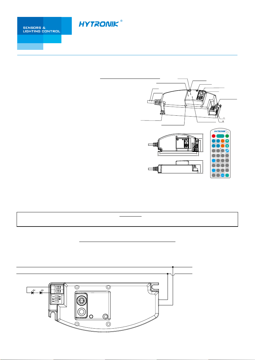
Installation hole
(screw D x L: 3 x 10mm)
101.1
110
HEC7028
Buzzer
Daylight sensor
LED indication
Infrared remote receiver
Rotary switch
LED current selection
Sensor antenna
35.5
4.1
29
31.6
23.7
LED
LED
ON/
Auto Mode
OFF
Power
SC1 SC2
100%
Scene mode
49.534.7
SC3
SC4
Detection range
100%
50% 10%
Stand-by dimming level
20%
10%
Test
30s 1min
2s
Hold-time
0s 10s 1min
Stand-by period
10min
30min
Power
80%
30%
30min10min5min
HRC-05
Technical Specifications
PRODUCT TYPE: Integrated sensorDIM LED driver
OPERATING VOLTAGE: 220-240VAC 50/60Hz
Cut-out size (L x D: 36 x 29.5mm)
L (Blue)
N (Brown)
HF SYSTEM: 5.8GHz CW radar
TRANSMISSION POWER: <0.2mW
°
DETECTION ANGLE: 30 ~150
DETECTION RANGE: Max. 8 meters in diameter, adjustable
TIME SETTING: 2s, 30s~30min.
°
Installation hole (4.1mm)
DAYLIGHT SENSOR: 2~50Lux; disable
STAND-BY PERIOD: 0s, 10s ~ +∞
STAND-BY DIMMING LEVEL: 10% ~30%
MOUNTING: Indoors, ceiling&wall mounted
INSTALLATION HEIGHT: ≤5M
WORKING TEMP.: -20~+50℃
This is a smart integration of microwave motion sensor and multiple
current selection LED driver, which gives pre-selected constant current
to drive the LEDs to work based upon movement detection. Designed
in the software and thanks to our worldwide patented circuit, the built-in
daylight sensor is prior to motion sensor so as to achieve utmost energy saving purpose.
Note: the high-frequency output of this sensor is <0.2mW; approximately just 1‰ of the transmission power of a mobile telephone or
the output of a microwave oven.
Reset
+
Dim
-
Daylight Sensor
2Lux
5min
10Lux
50Lux
Lux
Disable
M/A
PLEASE READ THESE INSTRUCTIONS CAREFULLY PRIOR TO INSTALLATION AND RETAIN THIS LEAFLET IN A KNOWN
AND SAFE PLACE FOR FUTURE REFERENCE.
IMPORTANT
SECTION 1 INSTALLATION AND WIRING
1.1 Ensure that the electricity supply is switched off before installing or servicing this product.
1.2 Wiring diagram
L
N
+
LED
LED
-
L
N
SECTION 2 FUNCTION
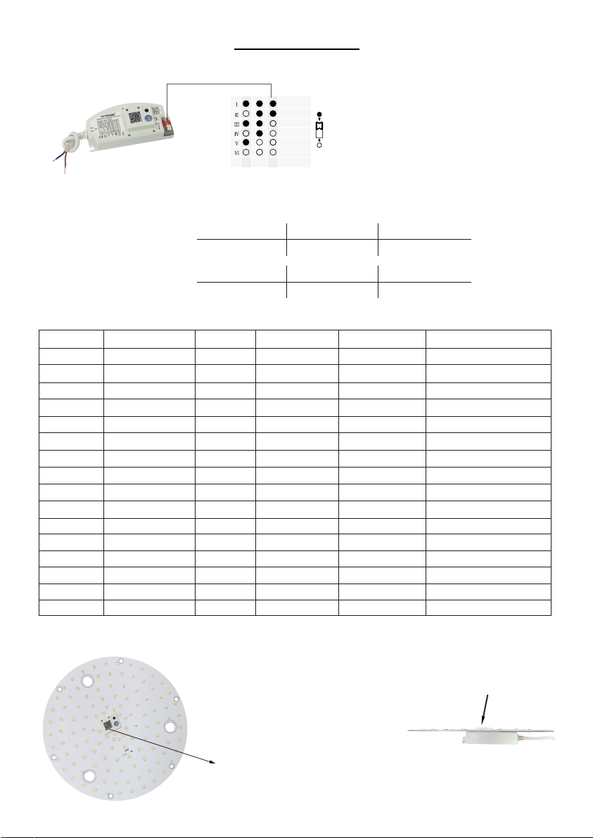
2.1 LED Current Selections
900mA
750mA
700mA
550mA
500mA
350mA
1 2 3
Current
2.2 LED Maximum Load and Voltage
This multiple current LED driver has a wide range of loading capacity:
Maximum load @ different currents:
3.5~17W (350mA) 5~24W (500mA) 5.5~25W (550mA)
7~28W (700mA) 7~28W (750mA) 9~28W (900mA)
The current can be easily configured by choosing
the correct combination of the DIP switches (see
table on the left).
Maximum voltage @ different currents:
10~48V (350mA) 10~48V (500mA) 10~46V (550mA)
10~40V (700mA) 10~37V (750mA) 10~31V (900mA)
2.3 Settings (Rotary Switch on Sensor Antenna)
Channel Detection range Hold-time Daylight sensor Stand-by period Stand-by dimming level
0 100% 5s Disable 10s 10%
1 100% 30s 2Lux 1min 10%
2 100% 1min 2Lux 5min 10%
3 100% 1min 10Lux 10min 10%
4 100% 1min Disable
+∞
10%
5 100% 5min 2Lux 10min 10%
6 100% 5min 10Lux 30min 10%
7 100% 5min Disable
+∞
10%
8 100% 10min 2Lux 10min 10%
9 100% 10min 10Lux 30min 10%
A 100% 10min Disable
+∞
10%
B 50% 10min Disable 30min 10%
C 10% 10min Disable 10min 10%
D 100% 30min 10Lux 30min 10%
E
F
100% 30min Disable +∞ 10%
100% 5s 2Lux 10s 10%
2.4 Assembly
The sensor antenna features the rotary
switch and protrudes the LED panel.
This feature enables the end user to
access the sensor settings without
removing the gear tray / LED board.
Sensor antenna
Note: end-user can also scan the QR
code on the housing for checking settings.
Cut-out size: 36 x 29.5 (mm)
 Loading...