

Hytronik HC419VRC/DH Installation And Instruction Manual
HC419VRC/DH-20170428-A1
Wire preparation
0.75-1.5
8mm
Dimensions (mm)
Fixture Built-in Microwave Sensor
Installation and Instruction Manual
HC419VRC/DH
This product utilises photocell advance
technology to realise occupancy and true
automatic photocell functions in one product.
The patented technology allows luminaire
design to be simplified as the luminaire body
no longer needs to be drilled to accept a
photocell for assessing the daylight condition.
This sensor can tell the difference of nature
light and artificial light (LED) from behind the
diffuser, and measure ambient natural light
then calculate how much artificial light is
needed to reach the target lux level. The need
is passed to the driver by 1-10V signal for
delivering the right amount of light.
The light will be dimmed to minimum level and
switched off eventually if ambient daylight is
sufficient, no matter it is during hold-time or
stand-by time, with or without motion.
Introduction
Technical Specifications
Product type Built-in microwave motion sensor (daylight harvest)
Operating voltage 120~277VAC 50/60Hz
Switched power Capacitive: 400VA/120VAC; 1000VA/277VAC
Resistive: 700W/120VAC; 1600W/277VAC
Stand-by power < 0.8W
Detection settings 10% / 50% / 75% / 100%
Hold time 2s / 5s / 30s / 1min / 3min / 5min /
10min / 15min / 20min / 30min
Stand-by time 0s / 10s / 1min / 5min / 10min / 30min / 1h / +
Stand-by dimming level 10% / 20% / 30% / 50%
Daylight threshold 2 ~ 500Lux , Disable
Detection area (DxH) 12 x 6 m
Microwave frequency 5.8 GHz +/- 75Mhz
Microwave power <0.2 mW
Warmming-up time 20s
Operating temperature -20
o
C ~ +60oC
8
Daylight Harvest
Installation
Please read this manual carefully before
installing the microwave sensor and siting the
luminaire.
Both the microwave sensor (antenna) and the
photocell elements of the product must be in
front of any metal work and have full line of
sight to the cover/diffusing element of the
fixture for trouble-free operation.
After Installing the sensor, it is highly
recommended that the luminaire is tested for
compatibility and correct operation of all
components.
Note: If testing under laboratory conditions,
the unique nature of this product requires full
bandwidth of the visible and invisible parts of
the electromagnetic spectrum, therefore it is
not recommended to attempt daylight
simulation with artificail light sources.
Not suitable for use with
Incandescent or Halogen
lamps
Not suitable for use in
installations where glass
is treated for reflection
of infrared radiation
Preparation of Luminaire
1. Positioning
This microwave sensor is ideal for use with LED
luminaires with the following considerations:
For simple mounting, the sensor may be placed on
the LED side of the LED PCB. The microwave
sensor will not be able to ‘see’ through any metal
components of the fixture. (See diagram 1
opposite).
For shadow-free operation, it is recommended that
the LED PCB is designed with a viewing window for
the sensor so that it may fit flush (or slightly proud)
of the LED PCB. (Please refer to diagram 2)
2. Configure the luminaire
Referring to the wiring diagrams overleaf, it is best
to consider terminations of the luminaires offered to
the installer dependant on system or project design.
If in any doubt, it is recommended that all 8
terminals of the sensor are made accessible to the
installer so that all of the features may be used if
required.
3. Wiring
To assist with installation, Hytronik use push-wire
style terminals. It is recommended that single core
(1/0.8mm for example) is used for making the
connections to the sensor.
The full specification for the wiring terminal is:
Detection area
Infrared remote receiver
Hold-time
Daylight sensor
Stand-by period
Stand-by dimming level
Daylight sensor 1
SYNC Push
L’ N L
1-10V +
1-10V-
Installation hole (4.2mm)
Sensor antenna
Daylight sensor 2
Buzzer
Diagram 2. Typical layout - behind LED PCB with cut-out
Diagram 1. Typical layout - in front of LED PCB
Base
LED PCB
Sensing direction
Sensing direction
Diffuser (Non-metal)
Glass less than 0.5cm
LED PCB
Cut-out 45mm x 31mm
22mm PCB support pillars
HC419VRC/DH-20170428-A1
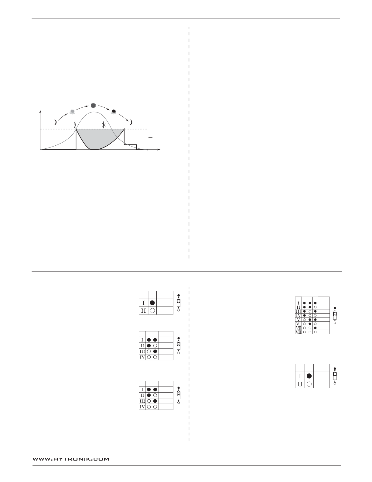
Settings
1. Detection Range
Sensor sensitivity can be adjusted by selecting the combination
on the DIP switches to fit precisely for each specific application.
2. Hold Time
Select the DIP switch configuation for the light on-time after
presence detection. This function is disabled when natural light
is sufficient.
3. Daylight Threshold
Set the level according to the fixture and environment. The light
will not turn on if ambient lux level exceeds the daylight
threshold preset. Please note the ambient lux level refers to
internal light reaching the sensor.
Disabling the daylight sensor will put the sensor into occupancy
detection only mode.
50%
1
100%
Disable
50Lux
10Lux
2Lux
4
5
4. Stand-by period
This is the time period you would like to keep at the low light
output level before it is completely switched off in the long
absence of people.
Note: “0s” means on/off control;
“+ ”means the stand-by period is infinite and the
light is effectively controlled by the daylight sensor,
off when natural light is sufficient and automatically
on at dimming level when insufficient.
5. Stand-by Dimming Level
The setting is used to select the desired dimmed light level
used in periods of absence for enhanced comfort and safety.
+
∞
0
s
1
0
s
5mi
n
10m
in
3
0
m
in
1H
8
6
7
1min
3
0
%
10
%
9
5s
3
min
2
3
1
0
min
30m
i
n
Functions
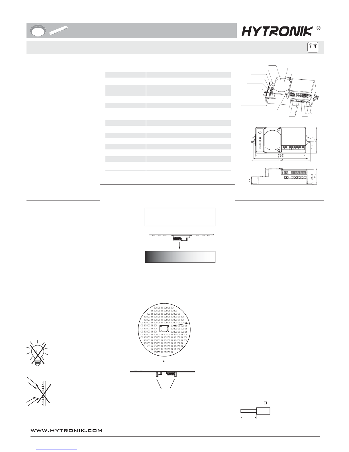
Daylight Harvest (Daylight Regulating)
Double L N terminal makes it easy for wire loop-in and loop-out, and saves the cost of
terminal block and assembly time.
Loop-in and loop-out terminal
Synchronization Control Function
By connecting the “SYNC” terminals in parallel (maximum 10pcs, see wiring diagram next
page), no matter which sensor detects motion, all HC419VRC/DH connected will turn on the
lights when surrounding natural light is below the daylight threshold which can be set by
either DIP switch on the sensor unit or remote control HRC-11. The sensor antennas are
effectively ‘shared’ and the detection area is widely enlarged in this way.
Note: To avoid fixtures turning on unnecessarily, daylight sensing takes priority on a
point-by-point basis. Occupancy sensing (SYNC) is disabled on those units in which the
ambient light exceeds the daylight threshold.
Designed in the software, sensor switches on/off the load right at the zero-cross point, to
ensure the in-rush current is minimised, enabling the maximum lifetime of the relay.
Zero-cross relay operation
Note:
1. The light will automatic turn on at target dim level or turn off based upon ambient natural
light lux level during stand-by period if it is preset to ‘+∞’.
2. The target lux level can be adjusted by remote control or long press on the push switch.
Photocell Advance (Lux off Function)
The built-in sensor can measure ambient natural light behind the diffuser, dim and eventually
switch off the fixture when artificial light is not required. What’s more, if the stand-by time is
pre-set at "+∞", the fixture can automatically turn on at dim level when natural light is
insufficient.
Manual Override (Push Function)
With the help of push-switch, this sensor maybe over-ridden by the end-users to switch
on/off the lights manually, or adjust the light brightness during motion hold-time. This
makes the product more user-friendly and offers more options to fit for extra-ordinary
demands.
* Short push (<1s): on/off function;
On → off: the light turns off immediately and cannot be lighten for a certain time
(equals to hold-time preset) even movement is detected. After this period, the
sensor goes to sensor mode.
Off → on: the light turns on 100% and goes to auto sensor mode, even when ambient
Lux level exceeds the daylight threshold.
* Long push (>1s): adjust the target lux level by turning the light up or down. Both the
adjustment on remote control and push switch can overwrite each
other, the last adjustment remains in memory.
Note: if no end-user adjustment is desired, simply leave the “push” terminal disconnected.
Semi-auto Function (absence detection)
Note: end-user can choose either Manual Override Function or Semi-auto Function application.
Default function is manual override (push function).
The motion sensor is employed, but only activated on the manual press of the push switch.
Light remains on during the presence and can interact with ambient natural light, then dims
down in absence, eventually switching off automatically after the stand-by time has expired.
The daylight sensor measures the available surrounding natural light and regulates the light
output from full brightness to minimum dim level, according to the change of daylight
brightness, so as to maintain the target lux level.
024
Light level
Time (hrs)
Normal Electric Light
Daylight controlled light
Energy Saving Zone
Natural light
Hold time
Stand-by time
8
 Loading...