

Hytronik HC419S Instruction Manual
Instruction Manual for Microwave Motion Sensor
On/off Version, Model No.:HC419S
Technical Specifications
SECTION 1 INSTALLATION & WIRING
IMPORTANT
PLEASE READ THESE INSTRUCTIONS CAREFULLY PRIOR TO INSTALLATION AND RETAIN THIS LEAFLET IN A KNOWN
AND SAFE PLACE FOR FUTURE REFERENCE.
1.1 Ensure that the electricity supply is switched off completely before installing or servicing this product.
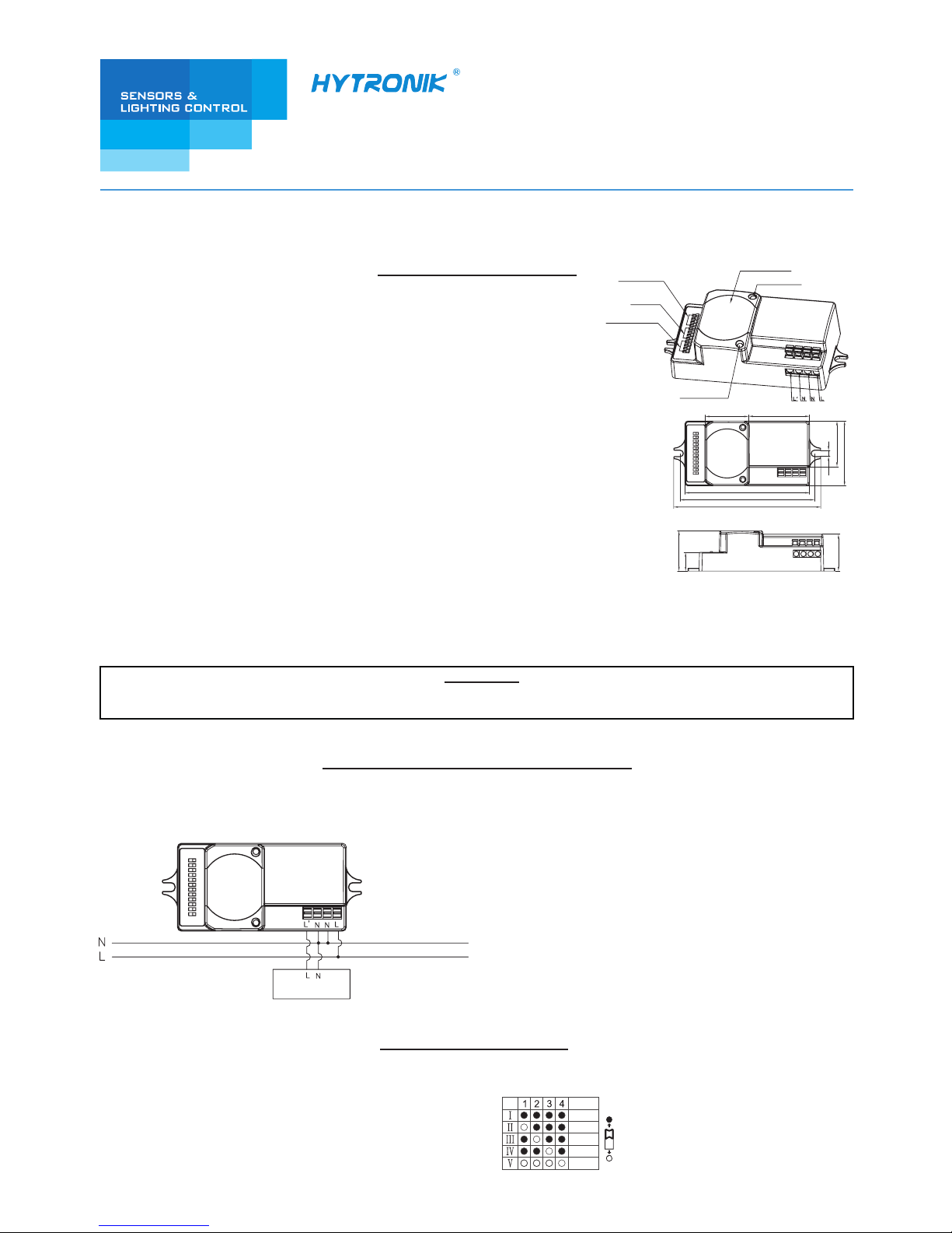
1.2 Wiring diagram:
I
– 100%
II
– 75%
III
– 50%
IV – 30%
V – 10%
Detection range can be tuned by selecting the combination on the DIP switches to fit precisely for each specific application.
PRODUCT TYPE: Microwave Motion Sensor
OPERATING VOLTAGE: 120-277VAC 50Hz/60Hz
HF SYSTEM: 5.8GHz+/-75MHz
TRANSMISSION POWER: <0.2mW
RATED LOAD: 120V~/3.4A/400W; 277V~/3.7A/1000W(capacitive load)
120V~/5.8A/700W; 277V~/5.8A/1600W(resistive load)
DETECTION ANGLE: 30
o
~ 150
o
POWER CONSUMPTION: < 1W
DETECTION RANGE: Max. 12 x 6m (DxH)
TIME SETTING: 5s~30min.
LIGHT CONTROL: 2~50Lux; disable
-35
o
C ~ +70oC
WORKING TEMP.:
MOUNTING:
Indoors, ceiling & wall mounted
The sensor is an active motion detector; it emits a high-frequency electro-magnetic wave at 5.8GHz and receives its echo. The
sensor detects the change in echo from movement in its detection zone. A microprocessor then trigers the switch light ON command.
Detection is possible throught doors, panes of glass and thin walls.
Note: the high-frequency output of this sensor is <0.2mW; approximately just 0.2‰ of the transmission power of a mobile telephone.
SECTION 2 SETTINGS
Detection range:
Antenna module
LED indication
Detection area
Hold-time
Daylight threshold
Daylight sensor
86.5
42.330.2
4.2
31.7
45
28
13
25.5
93.2
102
Control Gear
100%
75%
50%
30%
10%
3rd Floor, block C, complex building, 155#, Bai'gang road south,
Bai'gang village, Xiao Jin Kou town, Huicheng district, Huizhou 516023
Tel:86-752-2772020 F:86-752-2777877
E: info@hytronik.com W:www.hytronik.com
CHINA FACTORY
Room D, 10/f, Tower A, Billion Center, 1 wang Kwong Road,
Kowloon Bay, Kowloon, Hongkong
T: 00852-35197525 F: 00852-30116936
E: info@hytronik.com
HYTRONIK INDUSTRIAL LIMITED
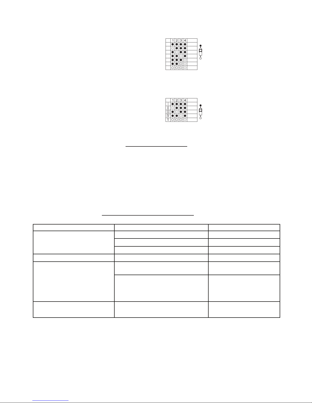
This setting determines the time period the lamp will remain at 100% upon detection.
Note: the timer is reset upon each motion detection.
The daylight threshold can be set on the DIP switches suit to the particular application.
SECTION 3 FUNCTIONS
Hold time:
Daylight sensor:
3.1 Zero-cross relay operation
SECTION 4 TROUBLE SHOOTING
MALFUNCTION CAUSE REMEDY CAUSE REMEDY
The load will not work
The load is always on
The load will not work
despite movement
Check zone setting
The load is on without any
identifiable movement
Incorrect light-control setting selected
Continuous movement in the detection zone
The sensor is not mounted for reliably
detecting movement
Movement occurred, but not identified by the
sensor (Movement behind wall, movement of
small object in immediate lamp vicinity etc.)
Rapid movements are being suppressed to
minimize malfunctioning or the detection
radius is too small.
Load faulty
Mains switch OFF
Adjust setting
Replace load
Switch ON
Check zone setting
Securely mount enclosure
1. Reduce sensitivity.
2. Check the movement behind
walls to avoid facilities such as
water pipe, fan, which may
mis-trigger the sensor.
I – Disable
II – 50Lux
III – 30Lux
IV – 10Lux
V – 2Lux
Disable
50Lux
30Lux
10Lux
2Lux
I – 5s
II – 30s
III – 1min
IV – 5min
V – 10min
VI – 20min
VII – 30min
I
II
III
IV
V
VI
VII
5s
30s
1min
5min
10min
20min
30min
3.2 Wire loop-in and loop-out
Designed in the software, sensor switches on/off the load right at the zero-cross point, to ensure the in-rush current is minimised,
enabling the maximum life-time of the relay.
Double L N terminal makes it easy for wire loop-in and loop-out, saves the cost of terminal block and assembly time.
 Loading...