

INSTRUCTION MANUAL FOR RF COMMUNICATION MICROWAVE MOTION SENSOR
MODEL NO.: HC028V/RF
Technical Specifications
This is a combination of motion sensor and RF radio wave wireless transmission. The motion detected by 1 sensor (the
master unit) can pass onto other pre-defined individuals (the slave units) through RF transmission. Thanks to fixed address
code technology, it’s easy to set up point-to-point or point-to multipoint transmission.
Note: the RF signal would be affected by big metal plate, frames, thick obstacle or special frequent electromagnetic waves
radiation.
Section 1 Installation and Wiring
1.1 Ensure that the electricity supply is switched off before installing or servicing this product.
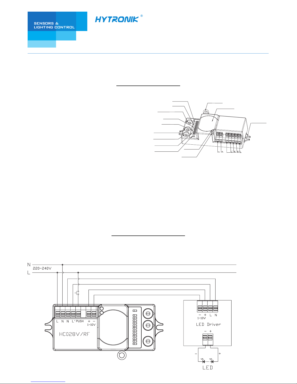
1.2 Wiring diagram
Product type:
Operation voltage:
Rated load:
HF detection range:
Time setting:
Stand-by period:
Stand-by dimming level:
Daylight threshold:
Installation height:
Working temperature:
HF system:
Coding system:
RF frequency:
RF transmission distance:
RF microwave motion sensor
220-240VAC 50/60Hz
400W (capacitive load)
Max. 12m in diameter, adjustable
5s ~ 30min.
0s, 10s ~ 1h, +∞
10% ~ 50%
2 ~ 50Lux, disable
Max. 6m
-20℃ ~ +60℃
5.8GHz CW radar
Fixed address coding with 16 channels
FSK 868MHz (315MHz / 433MHz / 915Mhz upon request)
30 meters indoor, 100 meters in open area
Antenna module
LED indication
Daylight sensor
RF antenna
Installation hole
1-10V
Push
Detection area
Hold-time
Rotary coding switch(TX)
Rotary coding switch(RX1)
Rotary coding switch(RX2)
Stand-by period
Stand-by dimming level
Brightness on RF signal
Daylight sensor
3rd Floor, block C, complex building, 155#, Bai'gang road south,
Bai'gang village, Xiao Jin Kou town, Huicheng district, Huizhou 516023
Tel:86-752-2772020 F:86-752-2777877
E: info@hytronik.com W:www.hytronik.com
CHINA FACTORY
Room D, 10/f, Tower A, Billion Center, 1 wang Kwong Road,
Kowloon Bay, Kowloon, Hongkong
T: 00852-35197525 F: 00852-30116936
E: info@hytronik.com
HYTRONIK INDUSTRIAL LIMITED
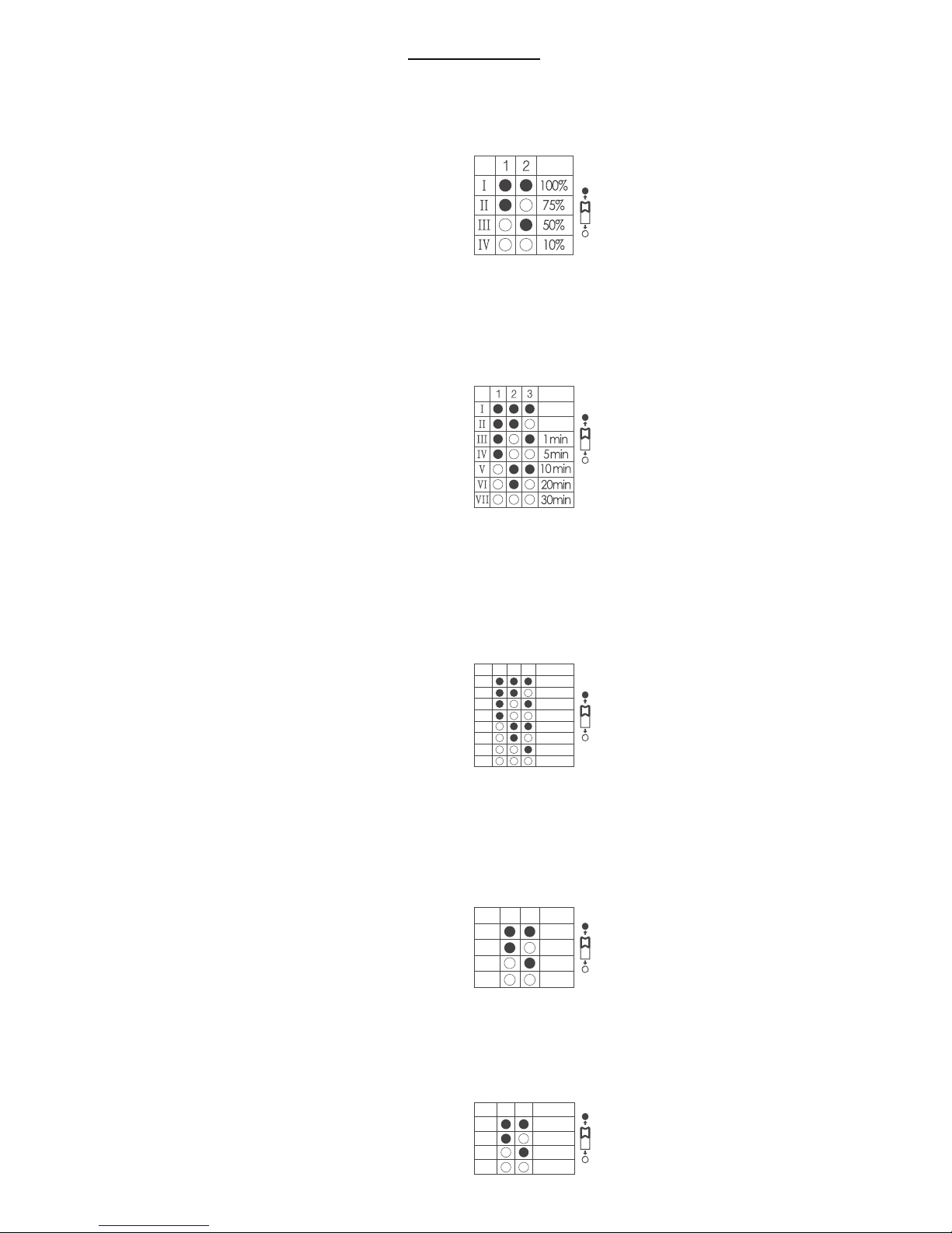
This determines the effective range of the motion detector and is set by DIP switches at the sensor itself, refer to figure. Note
that reducing the sensitivity will also narrow the detection range. The following settings are available:
Section 2 Settings
Detection Area
I – 100%
II – 75%
III – 50%
IV – 10%
This determines the time that the fitting remains at 100% level on motion detection and is set with DIP switches at the sensor
itself, refer to figure. The walk test setting is useful when installing the fitting to establish correct operation and range.
The following settings are available:
Hold time
This is the time period you would like to keep at the low light output level before it is completely switched off in the long
absence of people.
Note: “0s” means on/off control; “+∞” means bi-level dimming control, fixture never switch off.
Stand-by period (corridor function)
I – 5s
II – 30s
III – 1min
IV – 5min
V – 10min
VI – 20min
VII – 30min
5s
30s
I – 0s
II – 10s
III – 1min
IV – 5min
V – 10min
VI – 30min
VII – 1h
VIII - +∞
3
21
1H
+∞
0s
10s
1min
5min
10min
30min
I
II
III
IV
V
VI
VII
VIII
This is the dimmed low light output level you would like to have after the hold-time in the absence of people.
Stand-by dimming level
I – 10%
II – 20%
III – 30%
IV – 50%
21
10%
20%
30%
50%
I
II
III
IV
This setting holds off the 100% light output should there sufficient daylight and is set using DIP switches at the sensor, refer
to figure. The following settings are available:
Daylight sensor
I – Disable
II – 50Lux
III – 10Lux
IV – 2Lux
21
Disable
50Lux
10Lux
2Lux
I
II
III
IV

4.1 Zero-cross relay operation
Designed in the software, the sensor switches on/off the load right on the zero-cross point, to ensure the min. current passing
through the relay contact point, and enable the max. load and life-time of the relay.
4.2 Loop-in and loop-out
Double L N terminal makes it easy for wire loop-in and loop out, saves the cost of terminal block and assembly time.
4.3 Manual override
This sensor reserves the access of manual override function for end-users to switch on/off, or adjust the stand-by dimming
level with the push-switch, which makes the product more user-friendly, and more options to fit for some extra-ordinary
demands.
* Short push (<1s): on/off;
ON → OFF: the light turns off immediately and cannot be lighten for a certain time (equals to hold time preset) even
movement is detected. After this period, the sensor goes to auto sensor mode.
OFF → ON: the light turns on 100% and goes to sensor mode, even when ambient LUX level exceeds the daylight threshold.
* Long push (>1s): dim up/down the stand-by dimming level between 10% and 50%. Both the settings on DIP switch and
manual override can overwrite each other, the latest action stays in validity.
*If customers do not want to have this manual override function, we can just leave this “push” terminal alone ,
not connected to any wire.
Section 3 RF Grouping (Max. 16 channels)
Section 4 Functions
Using a screwdriver to adjust the rotary switch on both the master & slave unit, to keep them pointing at the same channel,
the grouping is then automatically completed. 16 channels (Max. 16 groups) are available for both the master & slave unit.
The sensor is not only a master but also a slave. It has three rotary switches, TX is for sending RF signal, RX1 and RX2 are
for receiving RF signal from two different groups of masters. Here is an example as below form FYI:
Note: the sensor installed on first floor and top floor receive one RF signal only, RX1 / RX2 point to the same channel.
Using a screwdriver to point the arrow to the same position on the master unit and slave units
TX
Floor No.
1
2
3
4
5
6
7
8
TX
0
1
2
3
4
5
6
7
RX1
1
0
1
2
3
4
5
6
RX2
1
2
3
4
5
6
7
6
RX
Master
Slave

Note: 1. Motion sensor overwrites daylight sensor, meaning the daylight sensor starts to check the ambient
natural light only when the lamp is switched off (motion hold-time elapsed).
2. 1-10V output on the master unit HC028V /RF is isolated, SELV output.
Section 5 Trouble Shooting
MALFUNCTION CAUSE REMEDY CAUSE REMEDY
The load will not work
The load is always on
The load will not work
despite movement
Check zone setting
The load is on without any
identifiable movement
Incorrect light-control setting selected
Continuous movement in the detection zone
The sensor is not mounted for reliably
detecting movement
Movement occurred, but not identified by the
sensor (Movement behind wall, movement of
small object in immediate lamp vicinity etc.)
Rapid movements are being suppressed to
minimize malfunctioning or the detection
radius is too small.
Load faulty
Mains switch OFF
Adjust setting
Replace load
Switch ON
Check zone setting
Securely mount enclosure
1. Reduce sensitivity.
2. Check the movement behind
walls to avoid facilities such as
water pipe, fan, which may
mis-trigger the sensor.
 Loading...