

Hytronik HC019V User Manual
NOTE:the high-frequency output of this sensor is <0.2mW;approximately just 1‰ of the transmission power of a mobile telephone or
the output of a microwave oven.
<0.2mW
800W(capacitive Load)
2~50LUX, disable
STAND-BY PERIOD: 0s, 10s-1h, +
WORKING TEMPERATURE:
∞
STAND-BY DIMMING LEVEL : 10% ~ 50%
Max. 12 meters in diameter, adjustable.
Approx. 0.8W
1.0
4
Nx2(neutral / 220-240VAC)
L (phase / 220-240VAC)
L’ (switched phase / output)
New advanced version Model No.:HC019V
The sensor works with a main voltage of 220-240VAC 50/60 Hz.100-120VAC version is available
on request.
Antenna module
Led indication
Detection area
Hold-time
Daylight threshold
Stand-by period
Stand-by dimming level
Daylight sensor
0-10V
output
Sync
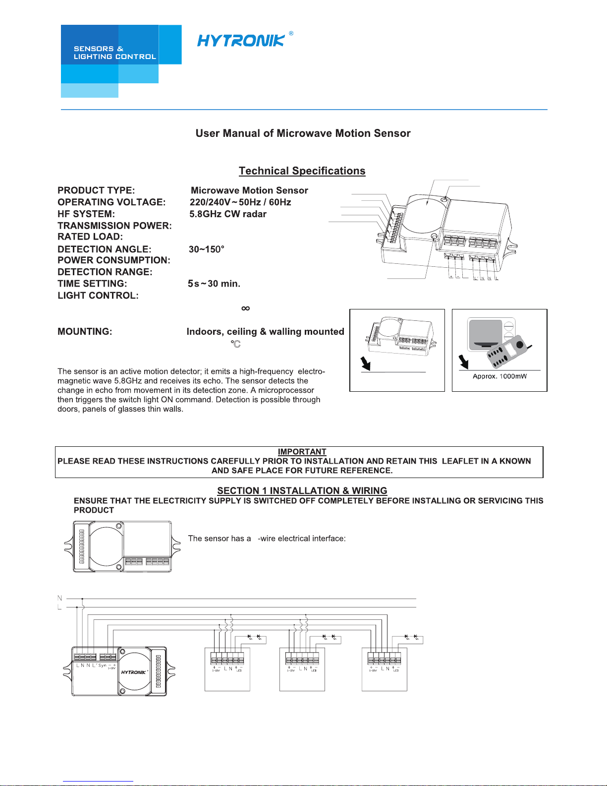
Wiring of 1 sensor controls a group of ballast /driver.
HC019V
MAX.800w
LED DriverLED Driver LED Driver
+
<0.2mW
-35 ~ +70℃
SYNC (synchronization interface)
+ (1-10V “+” interface)
- (1-10V “-” interface)
3rd Floor, block C, complex building, 155#, Bai'gang road south,
Bai'gang village, Xiao Jin Kou town, Huicheng district, Huizhou 516023
Tel:86-752-2772020 F:86-752-2777877
E: info@hytronik.com W:www.hytronik.com
CHINA FACTORY
Room D, 10/f, Tower A, Billion Center, 1 wang Kwong Road,
Kowloon Bay, Kowloon, Hongkong
T: 00852-35197525 F: 00852-30116936
E: info@hytronik.com
HYTRONIK INDUSTRIAL LIMITED
I – 0s
II – 10s
III – 1min
IV – 5min
V – 10min
VI – 30min
VII – 1h
VIII – +∞
This is the time period you would like to keep at the low light output level before it is completely switched off in the long absence
of people.
Note: “0s” means on/off control; “+∞” means 2 steps of dimming control, fixture never switch off.
Stand-by period (corridor function)
1h
10min
30min
5min
1min
10s
3
21
+
∞
0s
I
I I
III
IV
V
VI
VII
VIII
1.1 This sensor is suitable for indoor use, and is also designed for installation Max. 6m in height.
SECTION 2 SETTINGS
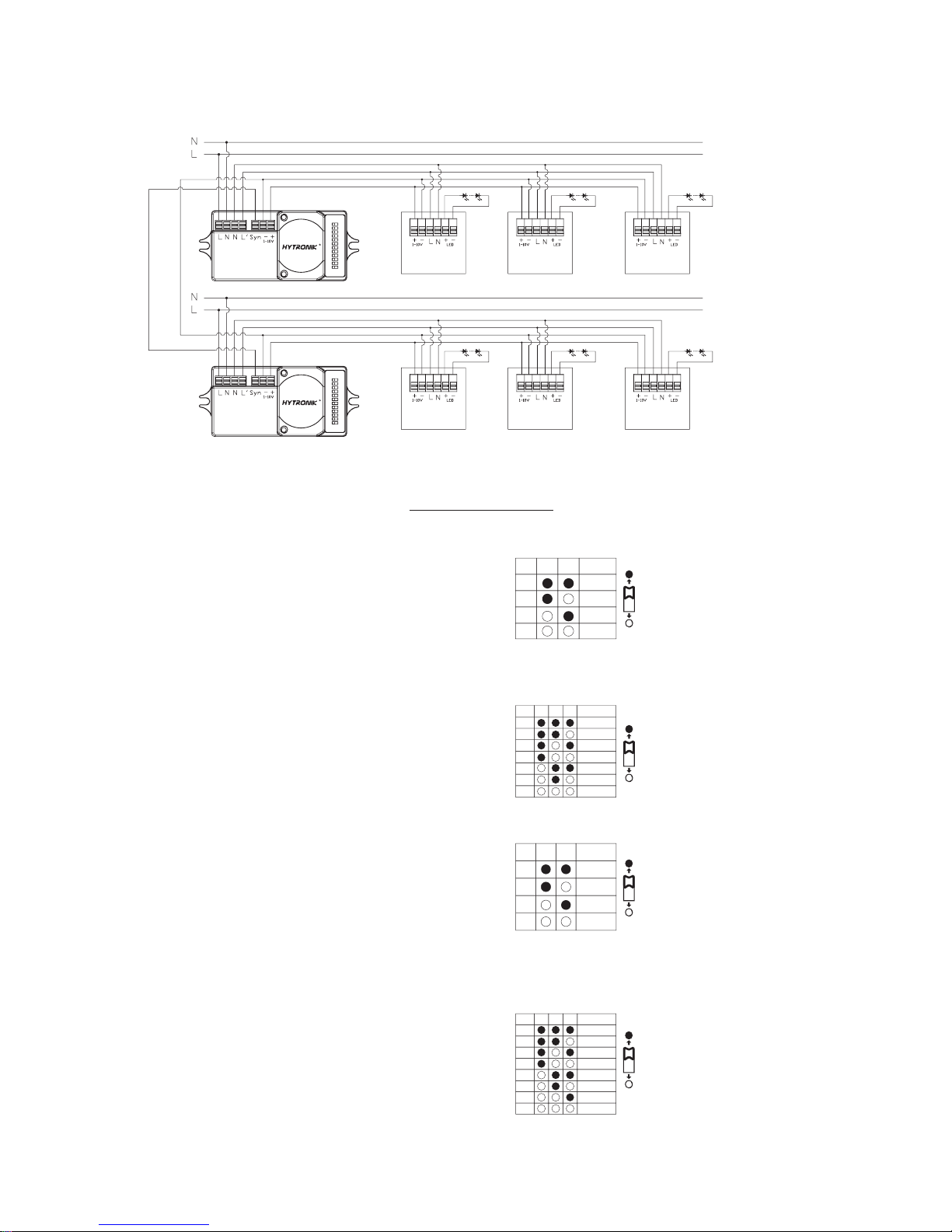
Detection Area:
This determines the effective range of the motion detector and is set by DIP switches at the sensor itself, refer to figure.
Note that reducing the sensitivity will also narrow the detection range.
The following settings are available:
Hold time:
This determines the time the fitting remains at 100% level on motion detection and is set with DIP switches at the sensor
itself, refer to figure. The walk test setting is useful when installing the fitting to establish correct operation and range.
The following settings are available:
Daylight sensor:
This setting holds off the 100% light output should there sufficient daylight and is set using DIP switches at the sensor, refer
to figure. The following settings are available:
*In disable mode the lamp(s) will always be on with motion detected
and operate at 100% light output, even in bright daylight.
I – 100%
II – 75%
III – 50%
IV – 10%
I – 5S
II – 30S
III – 1min
IV – 5min
V – 10min
VI – 20min
VII – 30min
I – Disable
II – 50Lux
III – 10Lux
IV – 2Lux
50 %
75%
100
%
10%
21
I
I I
III
I V
3
21
30min
5s
30s
1min
5min
10min
20min
I
I I
III
I V
V
VI
VII
21
50Lux
10Lux
2 Lux
Disable
I
I I
III
IV
HC019V
MAX.800w
HC019V
MAX.800w
Wiring of multiple sensors control the same group of ballast /driver, any sensor is triggered, the luminaries
in the group light up.
LED Driver XLED Driver XLED Driver X
LED Driver Y LED Driver Y LED Driver Y
Do not connect the 1-10v terminals on driver X to Driver Y.
*
 Loading...