


Installation and Instruction Manual
Bluetooth Motion Sensor - Built-in Detachable Version HCD038 + HBT01/HBT02
1. Technical Specifications
Transceiver Node (HBT01 / HBT02)
Sensor principle
Operation frequency
Transmission power
1
Detection range
Detection angle
Operation temperature
Case temperature (Max.)
Storage temperature
Relative humidity 0 ~ 90%
2
Control Base HCD038)
Mains voltage
Stand-by power
Load rating
Warming-up
EMC standard (EMC)
Safety standard (LVD)
Radio Equipment (RED)
Operation temperature
Case temperature (Max.)
IP rating
3. Wire Preparation
High Frequency (microwave)
5.8GHz +/- 75MHz
<0.2mW
/
Max. ( O x H) 8m x 3m
º
~ 150º
30
Ta: -20°C ~ +70°C
Tc: +80°C
-35°C ~ +55°C
IP20IP rating
2.4 GHz - 2.483 GHz Operation frequency (Bluetooth)
Max. 7 dBm Transmission power
15~30m Range (Typical )
220~240VAC 50/60Hz
<0.5W
30mA, 16VDC (max. 15 devices)
20s
EN55015, EN61000
EN60669, AS/NZS60669
EN300440, EN301489, EN62479, EN300328
-20°C ~ +55°C
Tc: +80°C
IP20
0.5 - 1.5
mm
2. Dimensions and Terminals
Transceiver Node (HBT01 / HBT02)
Photocell Advance
RJ12 connector
TM
Daylight Sensor
Reset
The cable length is around 30cm.
Control Base HCD038 (DALI output)
Sensor Antenna
Bluetooth Module
RJ12 Connector
DALI
Push
8mm
To make or release the wire from the terminal, use a screwdriver to push down the button.
4. HF Occupancy Detection Pattern
Ceiling mounted height(m)
1. The detection range is heavily influenced by antenna placement (angle of approch) and
different walking paces. It may be reduced to ( O x H) of 2 x 3m under certain
conditions (walking across).
2. Please refer to placement guidance provided later in this document .
10%
30%
/
50%
75%
L
N
30
120
21
4.5
4.5
110.5
HCD038 + HBT01 / HBT02 - 20190301-A1
5. HBT01/ HBT02 Antenna Installation and Placement Notes
To maximise the range in every direction, the following considerations should be taken into account when situating the antenna in the luminaire:
HBT01
The HBT01 contains both a HF microwave antenna and the bluetooth
transceiver module and are located within the device as per fig.1.
g.1.
HF Microwave Antenna
g.2.
Metallic Gear Tray
Opening under antenna
When the antenna is mounted to a metallic backplane, such as a gear
tray, a cut-out opening should be made as large as possible
as shown in fig.2.
If possible, try to position the sensor as far away as possible from the
LED Driver or other strong sources of HF interference.
g.3.
HBT02
The HBT02 contains only the bluetooth transceiver module and is
located in the same position as per fig.3. The same consideration to
mounting on metal gear trays is therefore also as per fig.2.
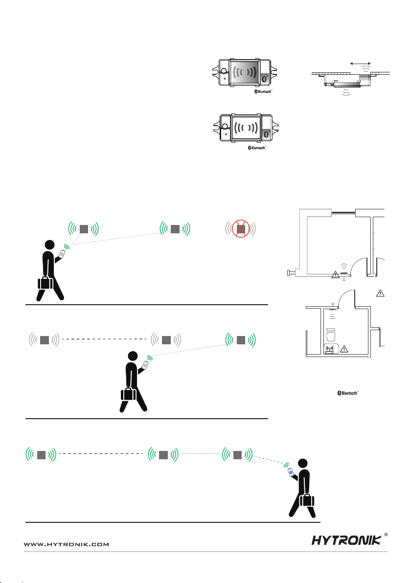
6. Basic Principle of Building the Hytronik Bluetooth Enabled Mesh Network
Smart Phone to Device Range
6-10m ͽ10m
Devices found within range of the smart device
will be listed in the device search. When the
devices are added and named, they will bind
and become part of the mesh network.
Device 1 Device 2
Nodes are added in the
mesh network and named,
for example, ‘Device 1’
and ‘Device 2’
Device 1 Device 2 Device 3
Even though device 1 & 2 are
in range of the smart device,
they will be hidden in a search
for new devices.
Antenna
Antenna
Notes:
The range for which a smart phone can communicate
with the switch points will vary from model to model
and is dependant on its capability.
Device placement will also effect the smart phone
communication range and may appear different for
each switch position.
Finally, other environmental factors (as above)
will influence the ultimate achievable range of
communication between smart phone and luminaire
device.
Device 1,2 and 3 are
all now in the mesh network
and will not be discoverable
under a new device search.
The mesh network is established and all
devices in the network will be accessible
in the devices screen,as long as the smart
device is in range of any node.
HCD038 + HBT01 / HBT02 - 20190301-A1

7. Wiring Diagram
DALI
DALI
L
N
DALI Driver
DALI
DALI
L
N
DALI Driver
HCD038
DALI
DALI
Push
N
L
L
N
8. Hardware Features
8.1 Manual Override (HCD038 / HC038V ‘Push’ Terminal)
The ‘push’ terminal reserves the access of manual override function for the end-user to switch on/off, or adjust the light level by push-switch. Furthermore, by using the binding option in the App, entire
groups of fixtures may be wirelessly controlled by a single switch. Please refer to the App user guide for further information.
* Short Push (<1s): permanent on/off function; can also be configured to recall scene selection.
* Long Push (>1s): Brightness level adjustment or colour tuning (colour tuning for DALI version only).
Notes:
1) Both the adjustment on App and push switch can overwrite each other, the last adjustment remains in memory.
2) The switch functions are configured in the App.
3) The push terminal may be left unconnected if no manual control is required.
TM
8.2 Photocell Advance
It is well known that LED lights have a totally different spectrum to natural light. Hytronik uses this principle with a custom-designed photocell and sophisticated software algorithm to measure and differentiate
natural light from LED light; the photocell can ignore the LED light and only respond to the natural light.
8.3 Zero-cross Relay Operation (HC038V)
Designed into the software, the relay switches the load right at the zero-crossing point, to ensure that the
in-rush current is minimised thus enabling the maximum lifetime of the relay.
8.4 Hardware Reset Button
A HBT01/HBT02 should always be removed from a network via the APP through the devices menu, and it is highly recommended that the hardware reset button is only used as a last resort, such as the
newtork to which it belonged has accidently been deleted from the smart device, or the account to which the network & device belongs to is irretrievable.
The reset button will erase the device from any mesh network it may have been added to.
Note: After the following process has been carried out, the device will not be able to communicate with the APP, so has no way to automatically “clear” itself from active networks on the smart device.
The device will show itself as a “new device” when performing a device search. When re-connecting to the network, the device setings will need to be re-configured as if connecting a new device.
To perform the reset:
* The HBT01/HBT02 must be connected and powered up.
* Press and hold the reset button until the lamp flashes twice to confirm the reset is complete (It will take around 2- 5 Seconds).
Function (Built into HBT01 / HBT02)
zero-crossing point
Alternating current
HCD038 + HBT01 / HBT02 - 20190301-A1
 Loading...