

Hytrol Conveyor ProSort 100 User Manual
Installation
and
Maintenance
Manual
with Safety Information
and Parts List
RECOMMENDED SPARE PARTS HIGHLIGHTED IN GRAY
IMPORTANT!
DO NOT DESTROY
Model ProSort 100
HYTROL CONVEYOR CO., INC.
© COPYRIGHT 2000–HYTROL CONVEYOR CO., INC.
Jonesboro, Arkansas
Manteca, California
Effective August, 2000
Bulletin #
471
IMPORTANTE!
NO DESTRUIR
Manual
de Instalación
y
Mantenimiento
con Información sobre Seguridad
y Lista de Partes
LAS PARTES DE REPUESTO RECOMENDADAS SE RESALTAN EN GRIS

2
● Table of Contents
●
Tabla de Contenido
Warning Signs . . . . . . . . . . . . . . . . . . . .3
INTRODUCTION
Receiving and Uncrating . . . . . . . . . . . .4
INSTALLATION
Installation Safety Precautions . . . . . . . .5
Location . . . . . . . . . . . . . . . . . . . . . . . .6
Conveyor Set-Up . . . . . . . . . . . . . . . . . .7
Electrical Equipment . . . . . . . . . . . . . .10
OPERATION
Operation Safety Precautions . . . . . . .12
Conveyor Start-Up . . . . . . . . . . . . . . . .12
MAINTENANCE
Maintenance Safety Precautions . . . . .13
Lubrication . . . . . . . . . . . . . . . . . . . . .13
Controllling the ProSort . . . . . . . . . . . .14
Drive Switch Checklist . . . . . . . . . . . . .20
Carrying Chain Installation . . . . . . . . .22
Locating the Spur . . . . . . . . . . . . . . . .24
Divert Switch Removal Procedure . . . .25
Trouble Shooting . . . . . . . . . . . . . . . . .26
Preventive Maintenance Checklist . . . .28
Preventive Maintenance Details . . . . . .30
How To Order Replacement Parts . . . .31
ProSort 131 Parts Drawing . . . . . . . . .32
ProSort 131 Parts List . . . . . . . . . . . . .36
Divert Switch Parts Drawing . . . . . . . .38
Divert Switch Parts List . . . . . . . . . . . .39
Safety Switch Assembly . . . . . . . . . . . .40
Señales de Advertencia . . . . . . . . . . . . .3
INTRODUCCION
Recepción y Desembalaje . . . . . . . . . . .4
INSTALACION
Seguridad en la Instalación . . . . . . . . . .5
Localización . . . . . . . . . . . . . . . . . . . . .6
Montaje . . . . . . . . . . . . . . . . . . . . . . . . .7
Equipo Eléctrico . . . . . . . . . . . . . . . . .10
OPERACION
Seguridad en la Operación . . . . . . . . .12
Arranque del Transportador . . . . . . . . .12
MANTENIMIENTO
Seguridad en el Mantenimiento . . . . . .13
Lubricación . . . . . . . . . . . . . . . . . . . . .13
Controlando el ProSort . . . . . . . . . . . .14
Revisión del Interruptor . . . . . . . . . . . .20
Instalación de Cadenas . . . . . . . . . . .22
Colocando las Espuelas . . . . . . . . . . .24
Remoción del Interruptor Desviador . . .25
Resolviendo Problemas . . . . . . . . . . . .27
Lista de Mantenimiento Preventivo . . .29
Detalles de Mantemiento . . . . . . . . . . .30
Como Ordenar Partes de Repuesto . . .31
Dibujo de Partes del ProSort 131 . . . . .32
Lista de Partes del ProSort 131 . . . . . .36
Dibujo del Interruptor Desviador . . . . . .38
Partes del Interruptor Desviador . . . . .39
Interruptor de Seguridad . . . . . . . . . . .40
3
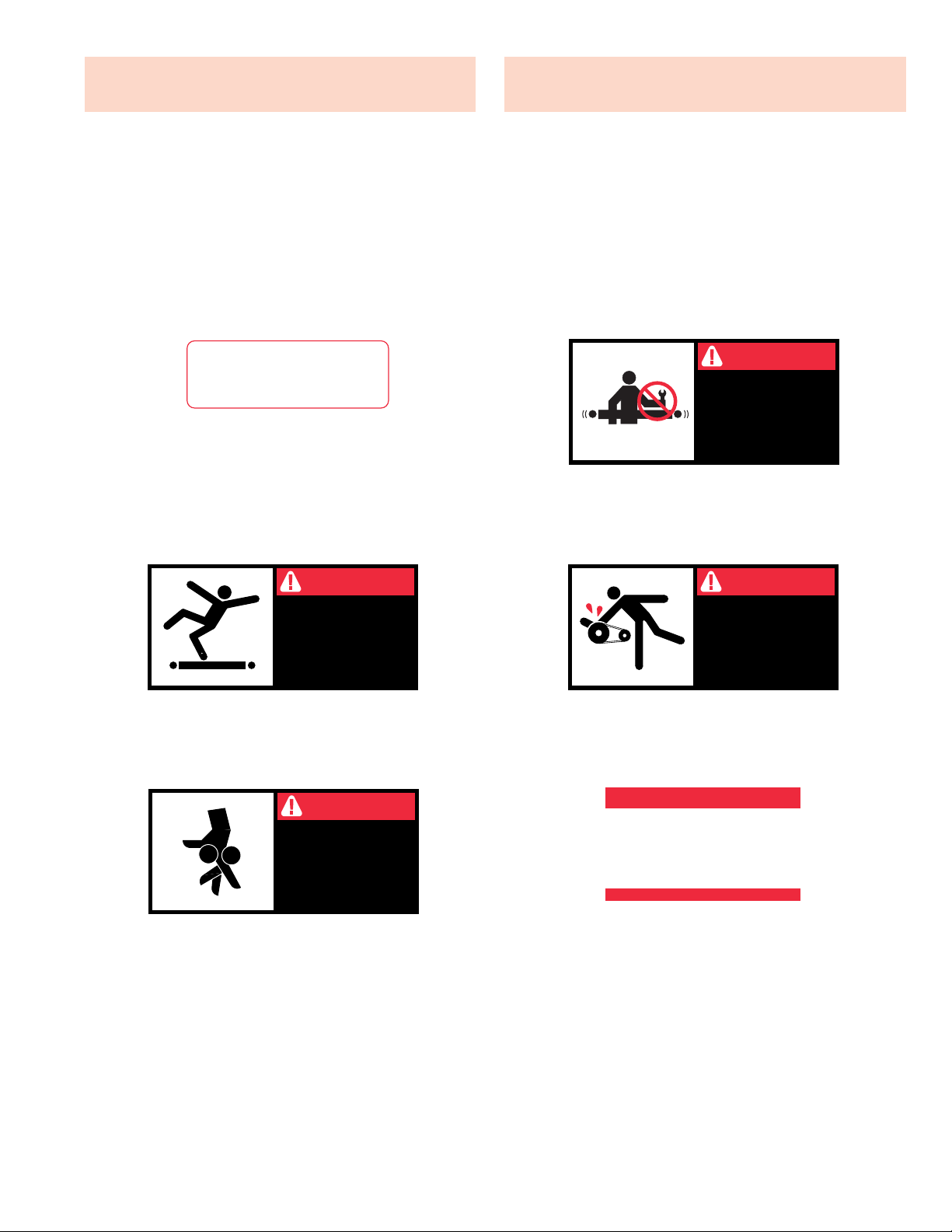
In an effort to reduce the possibility of injury to personnel
working around HYTROL conveying equipment, warning
signs are placed at various points on the equipment to alert
them of potential dangers. Please check equipment and
note all warning signs. Make certain your personnel are
alerted to and obey these warnings. Shown below are typical signs that are attached to this equipment.
En un esfuerzo por reducir la posibilidad de accidentes del
personal trabajando junto al equipo de transportación
HYTROL, se colocan señales de advertencia en diferentes
puntos del equipo para alertarlos de riesgos potenciales.
Por favor verifique el equipo y asegúrese de ver todas las
señales de advertencia. Asegúrese de que su personal esté
alerta y obedezca las señales. Abajo se muestran las
señales que se encuentran en este equipo.
● Warning Signs ●
Señales de Advertencia
PLACED ON ALL POWERED
CONVEYORS NEAR DRIVE
AND/OR CONTROLS.
PLACED NEXT TO DRIVE, BOTH
SIDES.
PLACED ON 20 FT.
INTERVALS,BOTH SIDES.
PLACED AT DRIVE OF ALL
POWERED CONVEYORS.
PLACED ON TERMINATING ENDS.
COLOCADAS EN TODOS LOS
TRANSPORTADORES
MOTORIZADOS CERCA AL
MOTOR Y/O LOS CONTROLES
COLOCADAS EN LA UNIDAD
MOTRIZ DE TODOS LOS TRANS-
PORTADORES MOTORIZADOS.
COLOCADAS EN INTERVALOS DE
20 PIES, AAMBOS LADOS.
COLOCADAS EN LOS EXTREMOS.
COLOCADAS JUNTO A LA UNIDAD
MOTRIZ, EN AMBOS LADOS.
DANGER
KEEP OFF
Climbing, sitting,
walking or riding on
conveyor at any time
will cause severe
injury or death
WARNING
LOCK OUT POWER
before removing
guard
Exposed moving
parts can cause
severe injury
WARNING
LOCK OUT POWER
before removing guard
Servicing moving or
energized equipment
can cause severe injury
WARNING
KEEP AWAY
Moving equipment
can cause severe
injury
WARNING!
DO NOT START CONVEYOR
UNTIL PERSONNEL ARE CLEAR
WARNING
DO NOT REMOVE THIS SIGN FROM THIS MACHINE
NEVER... START CONVEYOR UNTIL PERSONNEL ARE CLEAR
NEVER... LUBRICATE OR REPAIR WHILE CONVEYOR IS RUNNING
NEVER... RUN THE CONVEYOR WITH GUARDS REMOVED
NEVER...
NEVER...
ALLOW ANY PART OF YOUR BODY TO COME IN CONTACT
WITH THE CONVEYOR PULLEYS WHILE IT IS RUNNING.
IT IS THE EMPLOYERS RESPONSIBILITY TO IMPLEMENT THE ABOVE AND
ALSO TO PROVIDE ADEQUATE PROTECTION FOR ANY PARTICULAR USE,
OPERATION OR SERVICE.
PUT YOUR HANDS ON THE CONVEYOR OR IN THE
CONVEYOR WHEN IT IS RUNNING.
PLACED ON ALL CHAIN GUARDS.
COLOCADAS EN TODAS LAS
GUARDA CADENAS.

4
INTRODUCTION
This manual provides guidelines and procedures for
installing, operating, and maintaining your conveyor. A
complete parts list is provided with recommended spare
parts highlighted in gray. Important safety information is
also provided throughout the manual. For safety to personnel and for proper operation of your conveyor, it is recommended that you read and follow the instructions provided
in this manual.
Check the number of items received against the bill of
lading.
Examine condition of equipment to determine if any
damage occurred during shipment.
Move all crates to area of installation.
Remove crating and check for optional equipment that
may be fastened to the conveyor. Make sure these
parts (or any foreign pieces) are removed.
NOTE: If damage has occurred or freight is missing, see
the “Important Notice” attached to the crate.
1. . .
2. . .
3. . .
4. . .
INTRODUCCION
Este manual provee las pautas y los procedimientos para
instalar, operar, y mantener su transportador. Se proporciona una lista completa de repuestos, de los cuales, los
recomendados, estarán resaltados en gris. También se proporciona información importante de seguridad a lo largo de
este manual. Para seguridad del personal y para un funcionamiento apropiado del transportador, se recomienda
que se lean y se sigan las instrucciones proporcionadas en
este manual.
NOTA: Si algún daño ha ocurrido o falta cargamento,
vea las “Notas Importantes” adheridas al embalaje.
● Receiving and Uncrating
●
Recepción y Desembalaje
Verifique el número de partes recibidas con el
conocimiento del embarque.
Examine las condiciones del equipo para determinar si
algún daño ha ocurrido durante la transportación.
Mueva todo el equipo hacia el área de instalación.
Remueva todos los empaques y verifique si hay partes
opcionales que deben estar atadas al equipo.
Asegúrese de que estas partes (o cualquier otras
partes externas) sean removidas.
1. . .
2. . .
3. . .
4. . .

5
GUARDS AND GUARDING
Interfacing of Equipment. When two or more pieces of
equipment are interfaced, special attention shall be given to
the interfaced area to insure the presence of adequate
guarding and safety devices.
Guarding Exceptions. Wherever conditions prevail that
would require guarding under these standards, but such
guarding would render the conveyor unusable, prominent
warning means shall be provided in the area or on the
equipment in lieu of guarding.
Guarded by Location or Position. Where necessary for
the protection of employees from hazards, all exposed moving machinery parts that present a hazard to employees at
their work station shall be mechanically or electrically guarded, or guarded by location or position.
When a conveyor passes over a walkway, roadway, or work
station, it is considered guarded solely by location or position if all moving parts are at least 8 ft. (2.44 m) above the
floor or walking surface or are otherwise located so that the
employee cannot inadvertently come in contact with hazardous moving parts.
Although overhead conveyors may be guarded by location,
spill guard, pan guards, or equivalent shall be provided if the
product may fall off the conveyor for any reason and if personnel would be endangered.
HEADROOM
When conveyors are installed above exit passageways,
aisles, or corridors, there shall be provided a minimum
clearance of 6 ft. 8 in. (2.032 m) measured vertically from
the floor or walking surface to the lowest part of the conveyor or guards.
Where system function will be impaired by providing the
minimum clearance of 6 ft. 8 in. (2.032 m) through an emergency exit, alternate passageways shall be provided.
It is permissible to allow passage under conveyors with less
than 6 ft. 8 in. (2.032 m) clearance from the floor for other
than emergency exits if a suitable warning indicates low
headroom.
● Installation Safety
Precautions for Conveyors
and Related Equipment
GUARDAS Y PROTECCIONES
Unión del Equipo. Cuando dos o más piezas del equipo
van unidas, debe ponerse especial atención al área de
unión para asegurar que las guardas adecuadas y los dispositivos de seguridad estén presentes.
Excepciones de Protección. Dondequiera que las
guardas sean necesarias, pero que la colocación de las
mismas inhabilite el uso del transportador, se proporcionarán señales de advertencia visibles en el área o en el
equipo en vez de las guardas.
Protección dada por Posición o Ubicación. Cuando sea
necesaria la protección de los empleados contra posibles
riesgos, todas las partes del equipo que estén expuestas y
en movimiento, y que puedan presentar un peligro para
ellos en sus puestos de trabajo, serán protegidas mecánica
o eléctricamente, o protegidas por su posición o ubicación.
Cuando el transportador está instalado sobre pasillos,
corredores o puestos de trabajo, se considera protegido
únicamente por localización o posición si todas las partes
en movimiento están mínimo a 8 pies (2.44m) de altura del
piso, o si está localizado de tal manera que el empleado no
pueda entrar en contacto inadvertidamente con dichas
partes.
A pesar de que los transportadores áereos pueden estar
protegidos por su localización, guardas laterales e
inferiores deben ser proporcionadas para evitar que el producto se caiga del transportador y así mantener al
personal fuera de peligro.
UBICACION SUPERIOR
Cuando los transportadores son instalados sobre pasillos o
corredores de salida, debe dejarse un espacio libre de
mínimo 6 pies 8 pulgadas (2,032m) de extensión, medido
verticalmente desde el piso o área de tránsito hasta la parte
más baja del transportador o de las guardas.
Si se proporcionan señales de advertencia adequadas indicando baja altura, es posible dejar espacio libre con menos
de 6 pies 8 pulgadas (2.032m) de extensión entre el piso y
el transportador en aquellos pasillos que no sean salidas de
emergencia.
●
Medidas de Seguridad
al Instalar Transportadores
y Equipos Relacionados
INSTALLATION
INSTALACION
6
Refer to building layout for obstructions such as
machines, columns, walls, openings, etc. Check to see
that conveyor layout drawings correspond with building
layout.
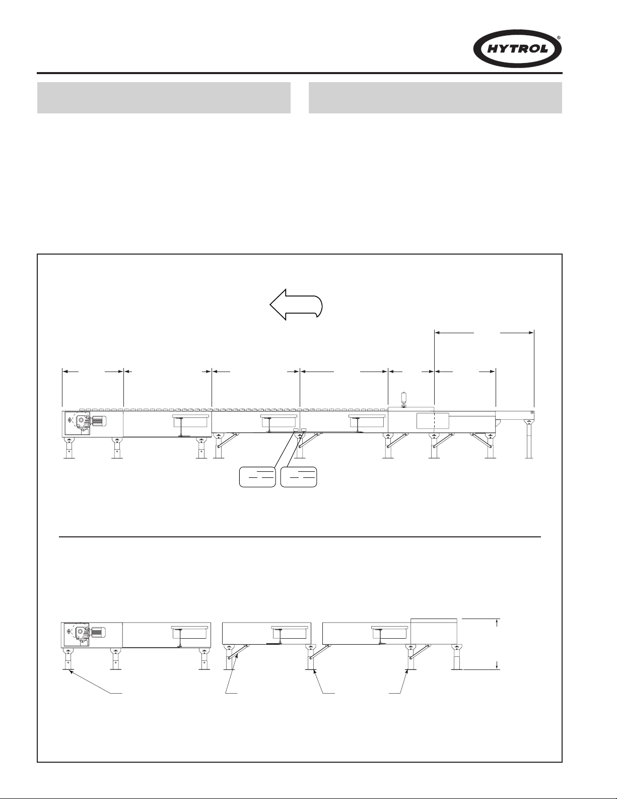
Determine direction of product flow. Figure 6A indicates the flow as related to the drive.
Refer to “Match-Mark” numbers on ends of conveyor
sections. (Figure 6A). Position them in this sequence
near area of installation.
Refiérase a la estructura del edificio para evitar que
cualquier maquinaria, columna o pared obstruya la ubicación del transportador. Revise que el plano sea el
correspondiente.
Determine el flujo del producto. La figura 6A indica el
flujo con relación al motor.
Use las etiquetas de secuencia ubicadas en el extremo
de cada sección de transportador para que sean colocadas en la posición correcta, cerca al área de instalación (Figura 6A).
● Location
1. . .
2. . .
3. . .
1. . .
2. . .
3. . .
CONVEYOR
ITEM TO
HYTROL CONVEYOR CO. INC.
JONESBORO, AR • MANTECA, CA
A
1
2
CONVEYOR
ITEM TO
HYTROL CONVEYOR CO. INC.
JONESBORO, AR • MANTECA, CA
A
2
1
DRIVE
(MOTOR)
CANTENARY DIVERT
(DESVIACION CATENARIA)
RETURN DIVERT
FLOW
(DESVIACION DE
RETORNO)
TAIL
(RETORNO)
INTERMEDIATE
DIVERT
(DESVIACION
INTERMEDIA)
INFEED BELT
DRIVE
(BANDA
ALIMENTADORA
MOTRIZ)
INFEED INDUCTION
BELT
(BANDA ALIMENT ADORA
DE INDUCCION)
"MATCH-MARK NUMBERS"
(ETIQUETAS DE SECUENCIA DE ARMADO)
DRIVE SUPPORT
(SOPORTE MOTRIZ)
KNEE BRACE
(SOPORTE ANGULAR)
ADJUST TO DESIRED
ELEVATION
(AJUSTE A LA AL TURA
DESEADA)
INTERMEDIATE
SUPPORTS
(SOPORTES INTERMEDIOS)
FIGURE 6A
●
Localización
FIGURE 6B

7
Mark a chalk line on floor to locate center of the conveyor.
Attach supports and vibration pads to all conveyor sections
shown in Figures 6B and 8A. Adjust elevation to required
height. Hand tighten bolts only at this time.
During installation, check to make sure each bed section
is square. Measure the diagonals from corner to corner of
the frame. If they are not equal the frame must be squared.
Attach a come-along or some other suitable pulling device
across longest corners and pull until the section is square.
Place the infeed (tail) section in position.
Install remaining sections, placing end without support on
extended pivot plate of previous section (Figure 6B).
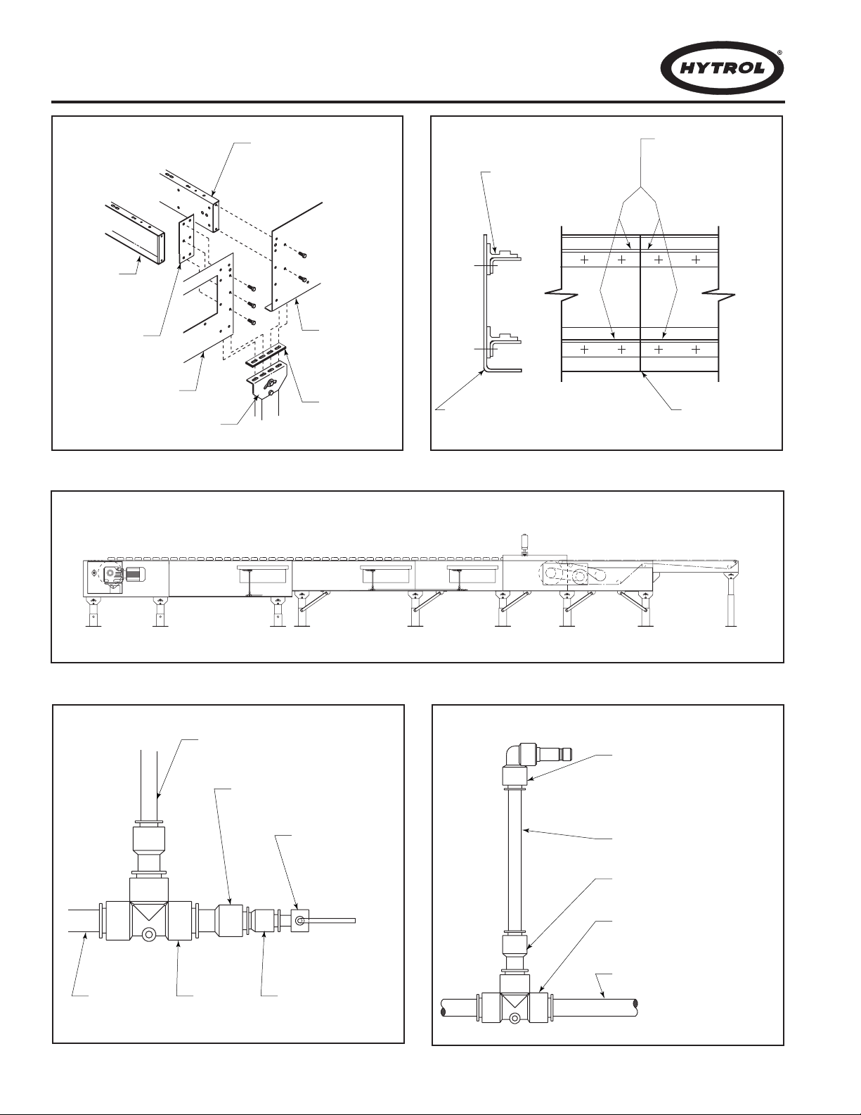
Fasten sections together with splice plates and pivot
plates. (Figure 8A). Hand tighten bolts only at this time.
Check to see that conveyor is level across the width and
length of unit. Adjust supports as necessary.
After all sections have been squared and levelled, tighten
all splice channels and support mounting bolts and lag
support to the floor.
Check alignment of wearstrip at all section joints. Sand
wearstrip as necessary to provide a smooth wear surface
(Figure 8B).
Fasten 1/2” main air line to bottom of conveyor channel
with cable ties (Figure 8C). Connect 3/8”air lines at divert
switches as shown in Figures 8D & 8E.
Connect main air line to the Filter/Regulator, Figure 9A. Set
regulator to working pressure of 60 P.S.I. Install low pressure switch, farthest point from regulator (Figure 8D).
Install electrical controls and wire motor. Verify correct
motor rotation at this time. See Page 10 for electrical control information.
Check each divert switch to see that it is operating properly . This must be done before carrying chains are installed.
See instructions on Page 20.
Check proximity switch clearance at each internal safety
switch (Figure 9C). Adjust if necessary.
Install carrying chains per instructions on Page 22.
Adjust pop-up roller assembly at discharge end to optimize
transition of packages from the ProSort to the take away
conveyor. Set pop-up roller proximity switch per Figure 9D.
Install chain oiler at infeed and connect to oil lines as
shown in Figure 9B. Refer to the Lubrication section, page
13 for type of oil required. After mounting, the oiler will need
to be adjusted for proper oiling of mounting chains.
Adjustment may be made using a combination of solenoid
activation time and flow adjustment screws. (Agood rule of
thumb for solenoid adjustment is to turn the oiler on for one
complete chain revolution for every 2 hours of sorter operation.) The chain on the divert side will typically need slightly more oil which may be accomplished using the flow
adjustment screws. CAUTION: Do not allow oil to drip on
floor.
Locate spurs per instructions on Page 24.
1. . .
2. . .
3. . .
4. . .
5. . .
6. . .
7. . .
8. . .
9. . .
10. . .
11. . .
12. . .
13. . .
14. . .
15. . .
16. . .
17. . .
18. . .
Marque con tiza una línea en el suelo para ubicar el centro
del transportador.
Una los soportes y los protectores de vibración a las secciones (Figuras 6B y 8A). Ajústelos a la altura requerida.
Apriete los tornillos manualmente.
Durante la instalación revise que cada sección de cama
esté encuadrada. Mida diagonalmente de esquina a
esquina del marco y encuadre si es necesario. Utilize un
tirante de encuadre o algo similar para el ajuste.
Ponga la sección del extremo alimentador.
Instale las secciones restantes poniendo el extremo sin
soporte en la placa pivote de la sección anterior (Fig. 6B).
Sujete las secciones con placas de unión y pivote (Fig 8A).
Apriete los tornillos manualmente.
Revise que el transportador esté nivelado a lo ancho y
largo. Ajuste los soportes como sea necesario.
Después de que todas las secciones hayan sido
encuadradas y niveladas apriete los empalmes de extremo
y los tornillos de montaje. Ancle el soporte al suelo.
Revise la alineación de la guía de cadena en todas las
uniones. Lije las tiras para obtener una superficie suave
(Fig. 8B).
Sujete 1/2” de la línea principal de aire a la parte inferior del
canal del transportador (Fig. 8C). Conecte 3/8” de la línea
de aire en el interruptor desviador (Fig. 8D & 8E).
Conecte la línea principal de aire al Filtro/Regulador (Fig.
9A). Ajuste el regulador a una presión de 60 PSI. Instale el
interruptor de baja presión lo más alejado posible del regulador (Fig. 8D).
Instale controles eléctricos y conecte el motor. Verifique la
correcta rotación del motor. Ver información eléctrica en la
página 10.
Revise cada interruptor desviador asegurándose de que
funcione correctamente. Esto debe hacerse antes de instalar las cadenas. Ver instrucciones en la página 20.
Revise el espacio libre del interruptor de proximidad en
cada terminal de seguridad (Fig 9C). Ajuste si es necesario.
Instale las cadenas; instrucciones en la Pag. 22.
Ajuste el ensamble de los rodillos de salida facil en la zona
de descarga para optimizar la transición de paquetes del
ProSort a una línea positiva. Ajuste el interruptor (Fig. 9D).
Instale el lubricador de cadena en el extremo alimentador y
conecte las líneas de aceite (Fig. 9B). Refiérase a la sección de lubricación (Pág. 13) para el tipo de aceite requerido. Después de instalado, el lubricador necesita ser ajustado para la lubricación de cadenas. El ajuste tendrá que ser
hecho usando una combinación de activador del ciclo de
solenoide y tornillos ajustadores del flujo (para el ajuste del
solenoide, el lubricador debe prenderse por una revolución
completa de cadena cada 2 hrs). La cadena del lado
desviador usualmente necesita más aceite que puede
suministrarse por medio de los tornillos ajustadores del
flujo. PRECAUCION: No permita que el aceite gotee al
piso.
Coloque las espuelas. Instrucciones en la página 24.
● Conveyor Set-Up
●
Montaje
1. . .
2. . .
3. . .
4. . .
5. . .
6. . .
7. . .
8. . .
9. . .
10. . .
11. . .
12. . .
13. . .
14. . .
15. . .
16. . .
17. . .
18. . .
8
SECTION JOINT
(SECCION DE UNION)
CONVEYOR CHANNEL
(CANAL DEL
TRANSPORTADOR)
WEARSTRIP CHAIN GUIDE
(GUIA DE CADENA)
CHAIN GUIDES MUST BE
EVEN AT JOINT
(LAS GUIAS DE CADENA
DEBEN SER UNIFORMES
EN LA UNION)
FIGURE 8A FIGURE 8B
FIGURE 8D FIGURE 8E
FIGURE 8C
END SWITCH
INTERMEDIATE SWITCHES
BED SPACER
(ESPACIADOR DE CAMA)
BED SPACER
(ESPACIADOR
DE CAMA)
SPLICE
(EMPALME)
SIDE CHANNEL
(CANAL LATERAL)
(PLACA PIVOTE)
PIVOT PLATE
SIDE CHANNEL
(CANAL LATERAL)
VIBRATION PAD
(PROTECTORES
DE VIBRACION)
LINE TO VALVE
(LINEA A LA VALVULA)
1/2" TO 3/8" REDUCER
(REDUCTOR DE 1/2" A 3/8")
PRESSURE SWITCH
PRE SET A T 48 PSI
(INTERRUPTOR DE
PRESION AJUSTADO
A 48 PSI)
3/8" FEMALE TO 3/8" MALE
QUICK CONNECT FITTING
PLUG INTO VALVE
(3/8" HEMBRA AL 3/8" MACHO
CONECTE EL ENCHUFE APROPIADO
EN LA VALVULA)
3/8" LINE
(LINEA DE 3/8")
1/2" to 3/8" REDUCER
(REDUCTOR DE 1/2" A 3/8")
MAIN AIR
(LINEA PRINCIP AL
DE AIRE)
1/2" TEE
(TE DE 1/2")
3/8" TO 1/4" REDUCER
(REDUCTOR DE 3/8" A 1/4")
1/2" TEE
(TE DE 1/2")
1/2" MAIN LINE
(LINEA PRINCIP AL DE 1/2")
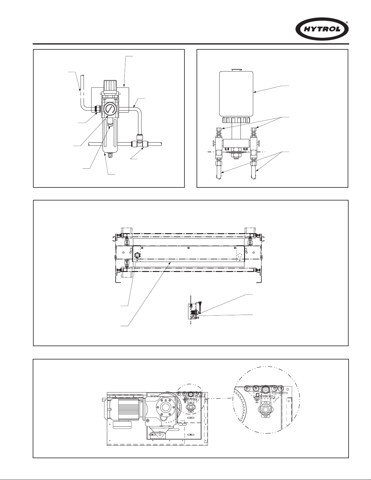
9
AIR SUPPLY T O
AIR VALVUES
(SUMINISTRO DE
AIRE A LAS
VAL VULAS)
1/2" UNION TEE
(UNION TE DE 1/2")
BOWL GUARD
(TAZON PROTECTOR)
FILTER/REGULATOR
(REGULADOR/FILTRO)
GAUGE
(MEDIDOR)
1/2" NPFT INLET
(ENTRADA DE
1/2" NPFT)
MAIN AIR
SUPPLY
LINE
(SUMINISTRO
PRINCIPAL
DE AIRE)
MOUNTING BRACKET
(FASTEN TO
CONVEYOR CHANNEL)
(PLACA DE MONT AJE
[SUJETAR AL CANAL
DEL TRANSPORT ADOR])
FIGURE 9A
FIGURE 9B
FIGURE 9C
FIGURE 9D
OIL CUP
(RECIPIENTE
DE ACEITE)
ADJUSTMENT SCREWS
(TORNILLOS DE AJUSTE)
OIL LINES TO BRUSHES
(LINEAS DE ACEITE
PARA LAS BROCHAS)
PROXIMITY SWITCH
(INTERRUPTOR DE PROXIMIDAD)
(INTERRUPTOR DEL SENSOR)
SWITCH SENSOR
PROXIMITY SWITCH
(INTERRUPTOR DE PROXIMIDAD)
SWITCH SENSOR
(INTERRUPTOR DEL SENSOR)

WARNING!
Electrical controls shall be installed and wired by a
qualified electrician. Wiring information for the motor
and controls are furnished by the equipment manufacturer.
CONTROLS
Electrical Code: All motor controls and wiring shall conform
to the National Electrical Code (Article 670 or other applicable articles) as published by the National Fire Protection
Association and as approved by the American Standards
Institute, Inc.
CONTROL STATIONS
A) Control stations should be so arranged and located that
the operation of the equipment is visible from them, and
shall be clearly marked or labeled to indicate the function
controlled.
B) A conveyor which would cause injury when started shall
not be started until employees in the area are alerted by a
signal or by a designated person that the conveyor is about
to start.
When a conveyor would cause injury when started and
is automatically controlled or must be controlled from a
remote location, an audible device shall be provided which
can be clearly heard at all points along the conveyor where
personnel may be present. The warning device shall be
actuated by the controller device starting the conveyor and
shall continue for a required period of time before the conveyor starts. Aflashing light or similar visual warning may be
used in conjunction with or in place of the audible device if
more effective in particular circumstances.
Where system function would be seriously hindered or
adversely affected by the required time delay or where the
intent of the warning may be misinterpreted (i.e., a work
area with many different conveyors and allied devices),
clear, concise, and legible warning shall be provided. The
warning shall indicate that conveyors and allied equipment
may be started at any time, that danger exists, and that personnel must keep clear. The warnings shall be provided
along the conveyor at areas not guarded by position or location.
C) Remotely and automatically controlled conveyors, and
conveyors where operator stations are not manned or are
beyond voice and visual contact from drive areas, loading
areas, transfer points, and other potentially hazardous locations on the conveyor path not guarded by location, position,
or guards, shall be furnished with emergency stop buttons,
pull cords, limit switches, or similar emergency stop
devices.
ADVERTENCIA!
Los controles eléctricos deben ser conectados e instalados por un electricista calificado. La información sobre
el cableado del motor y los controles será proporcionada
por el fabricante del equipo.
CONTROLES
Código Eléctrico: Todos los controles del motor y las
conexiones deben concordar con el National Electrical Code
(Artículo 670 u otros artículos aplicables) como fue publicado
por la “National Fire Protection Association” y aprobado por el
“American Standards Institute, Inc.”
ESTACIONES DE CONTROL
A) Las estaciones de control deberán estar arregladas y ubi-
cadas de tal forma que el funcionamiento del equipo sea visible y deberán estar claramente marcadas o señaladas para
indicar la función controlada.
B) Un transportador que pueda causar lesiones cuando es
puesto en marcha, no deberá ponerse en funcionamiento
hasta que los trabajadores en el área sean alertados por una
señal o por una persona designada que indique que el transportador está a punto de arrancar.
Cuando un transportador pueda causar lesiones al arrancar y sea controlado automáticamente, o tiene que ser controlado desde una ubicación lejana, se deberá proporcionar un
dispositivo sonoro el cual pueda ser escuchado claramente en
todos los puntos a lo largo del transportador donde el personal pueda estar presente. El dispositivo de advertencia
deberá ser activado por el dispositivo de arranque del transportador y deberá continuar sonando por un determinado
periodo de tiempo antes de que el transportador empiece a
funcionar. Una luz intermitente o una advertencia visual similar puede ser utilizada con o en lugar del dispositivo sonoro si
es más efectivo en circunstancias particulares.
Donde el funcionamiento del sistema pudiera ser
seriamente obstruído o adversamente afectado por el tiempo
de retardo requerido, o donde el intento de advertencia pueda
ser mal interpretado (ej., un área de trabajo con diversas
líneas de transportadores y los dispositivos de advertencia
relacionados), advertencias claras, concisas y legibles
deberán ser proporcionadas. Las advertencias deberán indicar
que los transportadores y los equipos relacionados pueden ser
puestos en marcha en cualquier momento, que existe un peligro y que el personal debe mantenerse alejado. Estas advertencias deben ser proporcionadas a lo largo del transportador
en áreas que no sean protegidas por la posición o la ubicación.
C) Los transportadores controlados automáticamente y desde
estaciones lejanas, y los transportadores donde las estaciones
de funcionamiento no estén controladas por una persona o
10
● Electrical Equipment
●
Equipo Eléctrico

11
All such emergency stop devices shall be easily identifiable in the immediate vicinity of such locations unless
guarded by location, position, or guards. Where the design,
function, and operation of such conveyor clearly is not hazardous to personnel, an emergency stop device is not
required.
The emergency stop device shall act directly on the control of the conveyor concerned and shall not depend on the
stopping of any other equipment. The emergency stop
devices shall be installed so that they cannot be overridden
from other locations.
D) Inactive and unused actuators, controllers, and wiring
should be removed from control stations and panel boards,
together with obsolete diagrams, indicators, control labels,
and other material which serve to confuse the operator.
SAFETY DEVICES
A) All safety devices, including wiring of electrical safety
devices, shall be arranged to operate in a “Fail-Safe” manner, that is, if power failure or failure of the device itself
would occur, a hazardous condition must not result.
B)
Emergency Stops and Restarts.
Conveyor controls shall
be so arranged that, in case of emergency stop, manual
reset or start at the location where the emergency stop was
initiated, shall be required of the conveyor(s) and associated equipment to resume operation.
C) Before restarting a conveyor which has been stopped
because of an emergency, an inspection of the conveyor
shall be made and the cause of the stoppage determined.
The starting device shall be locked out before any attempt
is made to remove the cause of stoppage, unless operation
is necessary to determine the cause or to safely remove the
stoppage.
Refer to ANSI Z244.1-1982, American National Standard for
Personnel Protection – Lockout/Tagout of Energy Sources
– Minimum Safety Requirements and OSHA Standard
Number 29 CFR 1910.147 “The Control of Hazardous
Energy (Lockout/Tagout).”
estén más allá del alcance de la voz y del contacto visual de
las áreas de conducción, áreas de carga, puntos de transferencia y otros sitios potencialmente peligrosos localizados
en la trayectoria del transportador que no tenga protección,
ya sea dada por posición, ubicación, o guardas, deberán ser
equipados con interruptores de parada de emergencia, cordones de parada de emergencia, interruptores de límite o
dispositivos similares.
Todos estos dispositivos de parada de emergencia
deberán ser fácilmente identificables en las cercanías
inmediatas a estos puntos potencialmente peligrosos, a no
ser que estén protegidos dada su ubicación, posición o protegidos con guardas. Donde el diseño, el funcionamiento, y
la operación de tales transportadores no represente un claro
peligro para el personal, no se requieren los dispositivos de
parada de emergencia.
El dispositivo de parada de emergencia deberá actuar
directamente en el control del transportador concerniente y
no deberá depender de la parada de cualquier otro equipo.
Los dispositivos de parada de emergencia deberán ser instalados de tal forma que no puedan ser anulados desde otras
localidades.
D) Los controles, los actuadores inactivos o no usados y los
cables, deberán ser removidos de las estaciones de control
y de los tableros de mando, junto con los diagramas, indicadores, etiquetas de control y otros materiales obsoletos,
los cuales se prestan para confundir al operador.
DISPOSITIVOS DE SEGURIDAD
A) Todos los dispositivos de seguridad, incluyendo la
conexión de dispositivos eléctricos, deben ser dispuestos
para operar en una manera de “autoprotección”; es decir, si
se presenta una pérdida de corriente o un fallo en el mismo
dispositivo, no debe presentarse una situación peligrosa.
B) Paradas de Emergencia y Reactivadores. Los controles
del transportador deberán estar dispuestos de tal manera
que en caso de una parada de emergencia, se requiera un
activador o arrancador manual en la ubicación donde la
parada de emergencia se presenta para reanudar la
operación del transportador o transportadores y el equipo
asociado.
C) Antes de volver a poner en marcha un transportador que
haya sido detenido por una emergencia, debe revisarse y
determinar la causa de la parada. El dispositivo de arranque
deberá ser bloqueado antes de intentar corregir o remover la
causa que originó la parada, a no ser que la operación del
transportador sea necesaria para determinar la causa o para
solucionar el problema de la parada sin ningún peligro.
Refiérase a ANSI Z244.1-1982, “American National
Standard for Personnel Protection” - Lockout/Tagout of
Energy Sources - Minimum Safety Requirements and OSHA
Standard Number 29 CFR 1910.147 “The Control of
Hazardous Energy (Lockout/Tagout).”

12
OPERATION
A) Only trained employees shall be permitted to operate conveyors.
Training shall include instruction in operation under normal conditions and
emergency situations.
B) Where employee safety is dependent upon stopping and/or starting
devices, they shall be kept free of obstructions to permit ready access.
C) The area around loading and unloading points shall be kept clear of
obstructions which could endanger personnel.
D) No person shall ride the load-carrying element of a conveyor under any
circumstances unless that person is specifically authorized by the owner
or employer to do so. Under those circumstances, such employee shall
only ride a conveyor which incorporates within its supporting structure,
platforms or control stations specifically designed for carrying personnel.
Under no circumstances shall any person ride on any element of a vertical conveyor. Owners of conveyors should affix warning devices to the
conveyor reading Do Not Ride Conveyor.
E) Personnel working on or near a conveyor shall be instructed as to the
location and operation of pertinent stopping devices.
F)A conveyor shall be used to transport only material it is capable of handling safely.
G) Under no circumstances shall the safety characteristics of the conveyor be altered if such alterations would endanger personnel.
H) Routine inspections and preventive and corrective maintenance programs shall be conducted to insure that all safety features and devices are
retained and function properly.
I) Personnel should be alerted to the potential hazard of entanglement in
conveyors caused by items such as long hair, loose clothing, and jewelry.
J) As a general rule, conveyors should not be cleaned while in operation.
Where proper cleaning requires the conveyor to be in motion and a hazard exists, personnel should be made aware of the associated hazard.
OPERACION
A) Solo se debe permitir operar los transportadores a empleados entrenados.
El entrenamiento debe incluir instrucciones de operación bajo condiciones
normales y en situaciones de emergencia.
B) Donde la seguridad de los trabajadores dependa de dispositivos de parada y/o arranque, éstos deberán mantenerse libres de obstrucciones para permitir un acceso rápido.
C) El área alrededor de los puntos de carga y descarga debe mantenerse
libre de obstrucciones, las cuales podrían poner en peligro al personal.
D) Ninguna persona debe montarse en la parte de conducción de carga de
un transportador bajo ninguna circunstancia al menos que esta persona esté
específicamente autorizada por el dueño o por el supervisor. Bajo estas circunstancias, el empleado deberá montarse solamente en un transportador
que tenga incorporado dentro de su estructura, plataformas o estaciones de
control especialmente diseñadas para el traslado de personal. Bajo ninguna
circunstancia, persona alguna debe subirse en cualquier parte de un transportador vertical. Los dueños de los transportadores deben añadir señales de
advertencia al transportador con el texto: “No Montarse en el Transportador”.
E) El personal que esté trabajando en o cerca al transportador, deberá ser
instruído en cuanto a la ubicación y operación de los dispositivos pertinentes
de parada.
F)Un transportador deberá ser usado para transportar solo los productos que
sea capaz de manejar seguramente.
G) Bajo ninguna circunstancia deberán ser alteradas las características de
seguridad de un transportador, si tales alteraciones pudieran poner en peligro
al personal.
H) Inspecciones rutinarias deberán llevarse a cabo al igual que programas
preventivos y correctivos de mantenimiento, para asegurar que todos los dispositivos y medidas de seguridad sean conservados en buen estado y funcionen correctamente.
I) El personal deberá ser avisado de peligros potenciales como enredos en
transportadores causados por materiales como cabello largo, ropa suelta o
joyas.
J) Como regla general, los transportadores no deberán limpiarse mientras
estén en funcionamiento. Cuando se requiera limpiar el transportador
estando en movimiento y exista posibilidad de peligro, el personal deberá ser
avisado de este riesgo.
● Conveyor Start-Up
Before conveyor is turned on, check for foreign objects that may
have been left inside conveyor during installation. These objects
could cause serious damage during start-up.
After conveyor has been turned on and is operating, check motors,
reducers, and moving parts to make sure they are working freely.
●
Arranque del Transportador
PRECAUCION!
Debido a la cantidad de partes en movimiento del transportador, todo el personal en el área del transportador
necesita ser advertido de que este está a punto de
ponerse en marcha.
Antes de poner en marcha el transportador, revise si hay objetos
ajenos que puedan haber sido dejados dentro del transportador
durante la instalación. Estos objetos pueden causar serios daños
en el arranque.
Después de que el transportador arranque y esté operando, verifique los motores, reductores y partes en movimiento para estar
seguro de que están trabajando libremente.
CAUTION!
Because of the many moving parts on the conveyor, all
personnel in the area of the conveyor need to be
warned that the conveyor is about to be started.
● Operation Safety Precautions
●
Medidas de Seguridad

13
MAINTENANCE
A) Maintenance, such as lubrication and adjustments, shall
be performed only by qualified and trained personnel.
B) It is Important that a maintenance program be established
to insure that all conveyor components are maintained in a
condition which does not constitute a hazard to personnel.
C) When a conveyor is stopped for maintenance purposes,
starting devices or powered accessories shall be locked or
tagged out in accordance with a formalized procedure
designed to protect all person or groups involved with the conveyor against an unexpected start.
D) Replace all safety devices and guards before starting
equipment for normal operation.
E) Whenever practical, DO NOT lubricate conveyors while
they are in motion. Only trained personnel who are aware of
the hazard of the conveyor in motion shall be allowed to lubricate.
SAFETY GUARDS
Maintain all guards and safety devices IN POSITION and IN
SAFE REPAIR.
WARNING SIGNS
Maintain all warning signs in a legible condition and obey all
warnings. See Page 3 of this manual for examples of warning
signs.
BEARINGS
A) NO GREASE FITTING—Prelubricated—No lubrication
required.
B) WITH GREASE FITTING—Relubricate approximately
every 10 to 12 weeks with lithium base grease suitable for ball
bearing service.
RECOMMENDED CHAIN LUBRICANT
40° F to 100° F SAE-20W- Non-detergent
20° F to 39° F SAE-10W- Non-detergent
Other aproved alternative lubricant include:
- LPS magnum Teflon Lubricant.
- Engage hightech Lubricant with Teflon.
REDUCERS
See recommendations by manufacturer.
MANTENIMIENTO
A) El mantenimiento, tal como lubricación y ajustes, debe ser
realizado solamente por personal calificado y entrenado.
B) Es importante que se establezca un programa de mante-
nimiento, para asegurar que todos los componentes del transportador sean mantenidos en condiciones que no constituyan
un peligro para el personal.
C) Cuando un transportador esté parado por razones de mantenimiento, los dispositivos de arranque o accesorios motorizados
deberán ser asegurados o desconectados conforme a un
procedimiento formalizado, diseñado para proteger de cualquier
arranque inesperado a toda persona o grupos de personas
involucrados con el transportador.
D) Antes de poner en marcha el equipo, vuelva a colocar todos
los dispositivos de seguridad y las guardas.
E) Siempre que sea práctico, NO lubrique los transportadores
mientras se encuentren en movimiento. Solo el personal entrenado, que tenga conocimiento de los peligros del transportador
en movimiento, se le permitirá lubricarlos de esta manera.
PROTECCIONES DE SEGURIDAD
Mantenga todas las guardas y dispositivos de seguridad EN SU
POSICION y EN BUENAS CONDICIONES.
SEÑALES DE ADVERTENCIA
Mantenga todas las señales de advertencia en condiciones
legibles y obedézcalas. Remítase a la página 3 de este manual
para ver ejemplos de señales de advertencia.
RODAMIENTOS
A) SIN NECESIDAD DE LUBRICACION—Prelubricados
B) DE LUBRICACION—Lubricar cada 10 a 12 semanas con
aceite a base de litio apropiado para los balines de los rodamientos
LUBRICANTES DE CADENA RECOMENDADOS
40° F a 100° F SAE-20W- No-detergente
20° F a 39° F SAE-10W- No-detergente
Otros lubricantes alternativos aprovados son:
-Lubricante “LPS Magnum Teflon Lubricant.”
-Lubricante “Engage Hightech Lubricant with Teflon.”
REDUCTORES
Refiérase a las recomendaciones de su fabricante.
● Lubrication
●
Lubricación
● Maintenance Safety
Precautions
●
Medidas de Seguridad
en el Mantenimiento
 Loading...