

Hytrol Conveyor 199-CREZD, 36-CREZD, 25-CREZD User Manual
IMPORTANT!
DRIVE
SYSTEM
™
TM
¡IMPORTANTE!
DO NOT DESTROY
NO DESTRUIR
Installation
and
Maintenance
Manual
with Safety Information
and Parts List
RECOMMENDED SPARE PARTS HIGHLIGHTED IN GRAY
Manual
de Instalación
y
Mantenimiento
con Información sobre Seguridad
y Lista de Partes
LAS PARTES DE REPUESTO RECOMENDADAS SE RESALTAN EN GRIS
Models 199-CREZD,
25-CREZD & 36-CREZD
Effective February 2008
Bulletin #600
HYTROL CONVEYOR CO., INC.
© COPYRIGHT 2008–HYTROL CONVEYOR CO., INC.
Jonesboro, Arkansas

l Table of Contents l
Tabla de Contenido
Warning Signs . . . . . . . . . . . . . . . . . . . . .3
INTRODUCTION
Receiving and Uncrating . . . . . . . . . . . . .4
INSTALLATION
Installation Safety Precautions . . . . . . . .5
Support Installation . . . . . . . . . . . . . . . . .6
Conveyor Set-Up . . . . . . . . . . . . . . . . . . .8
Electrical Equipment . . . . . . . . . . . . . . .10
Sequence of Operation . . . . . . . . . . . . .12
EZLogic® System . . . . . . . . . . . . . . . . .14
EZDrive™ Zone Starter Box . . . . . . . . .16
Loading Applications . . . . . . . . . . . . . . .18
Unloading Applications . . . . . . . . . . . . .21
OPERATION
Operation Safety Precautions . . . . . . . .24
Conveyor Start-Up . . . . . . . . . . . . . . . .25
MAINTENANCE
Maintenance Safety Precautions . . . . .26
Lubrication . . . . . . . . . . . . . . . . . . . . . . .27
Trouble Shooting . . . . . . . . . . . . . . . . . .28
Maintenance Checklist . . . . . . . . . . . . .30
How To Order Replacement Parts . . . .30
REPLACEMENT PARTS
Model 199-CREZD Parts Drawing . . . .32
Model 199-CREZD Parts List . . . . . . . .34
Model 25-CREZD Parts Drawing . . . . .35
Model 25-CREZD Parts List . . . . . . . . .37
Model 36-CREZD Parts Drawing . . . . .38
Model 36-CREZD Parts List . . . . . . . . .40
Señales de Advertencia
. . . . . . . . . . . . .3
INTRODUCCION
Recepción y Desembalaje
. . . . . . . . . . .4
INSTALACION
Medidas de Seguridad
Al Instalar
Instalación de los Soportes
Montaje del Transportador
Equipo Eléctrico
Secuencia de Operación
Sistema EZLogic®
. . . . . . . . . . . . . . . . . . . . . .5
. . . . . . . . . . .6
. . . . . . . . . . .8
. . . . . . . . . . . . . . . . . .10
. . . . . . . . . . . .12
. . . . . . . . . . . . . . . .14
Motor Controlador EZDrive™
Aplicaciones de Carga
Aplicaciones de Descarga
. . . . . . . . . . . . .18
. . . . . . . . . .21
OPERACION
Medidas de Seguridad
Arranque del Transportador
. . . . . . . . . . . . .24
. . . . . . . . .25
MANTENIMIENTO
Medidas de Seguridad
Lubricación
. . . . . . . . . . . . . . . . . . . . . .27
Resolviendo Problemas
. . . . . . . . . . . . .26
. . . . . . . . . . . .29
Lista del Plan de Mantenimiento
Como Ordenar Partes de Repuesto
PARTES DE REPUESTO
Modelo 199-CREZD Dibujo de Partes
Modelo 199-CREZD
Lista de Partes
. . . . . . . . . . . . . . . . . .34
Modelo 25-CREZD Dibujo de Partes
Modelo 25-CREZD
Lista de Partes
. . . . . . . . . . . . . . . . . .37
Modelo 36-CREZD Dibujo de Partes
Modelo 36-CREZD
Lista de Partes
. . . . . . . . . . . . . . . . . .40
. . . . . . . .16
. . . . .31
. . .31
.32
. .35
. .38
2
l Warning Signs l
DANGER
Climbing, sitting,
walking or riding on
conveyor at any time
w
ill cause severe
injury or death
KEEP OFF
WARNING
Exposed moving
parts can cause
severe injury
LOCK OUT POWER
before removing
guard
WARNING
Servicing moving or
energized equipment
can cause severe injury
LOCK OUT POWER
before removing guard
WARNING
Moving equipment
can cause severe
injury
KEEP AWAY
WARNING!
DO NOT START CONVEYOR
U
NTIL PERSONNEL ARE CLEAR
WARNING
DO NOT REMOVE THIS SIGN FROM THIS MACHINE
NEVER...
START CONVEYOR UNTIL PERSONNEL ARE CLEAR
NEVER...
L
UBRICATE OR REPAIR WHILE CONVEYOR IS RUNNING
NEVER...
RUN THE CONVEYOR WITH GUARDS REMOVED
NEVER...
NEVER...
ALLOW ANY PART OF YOUR BODY TO COME IN CONTACT
WITH THE CONVEYOR PULLEYS WHILE IT IS RUNNING.
IT IS THE EMPLOYERS RESPONSIBILITY TO IMPLEMENT THE ABOVE AND
A
LSO TO PROVIDE ADEQUATE PROTECTION FOR ANY PARTICULAR USE,
OPERATION OR SERVICE.
PUT YOUR HANDS ON THE CONVEYOR OR IN THE
CONVEYOR WHEN IT IS RUNNING.
WARNING
Equipment starts
automatically can cause severe
injury
KEEP AWAY
PELIGRO!
?
CONSERVE DISTANCIA
Subirse, sentarse,
caminar o viajar
en el transportador
en cualquier momento,
puede causar lesiones
graves o incluso la muerte.
Partes expuestas en
movimento pueden
causar lesiones graves.
ADVERTENCIA!
DESCONECTAR la
energia antes de
remover la guarda.
ADVERTENCIA!
El mantenimiento de
partes eléctricas o en
movimiento puede
causar lesiones graves.
DESCONECTAR la energia
antes de remover la guarda.
ADVERTENCIA!
Partes en movimiento
pueden causar
lesiones graves.
NO SE ACERQUE
¡ADVERTENCIA!
NO PONER EN MARCHA EL TRANSPORTADOR
HASTA QUE TODO EL PERSONAL ESTE ALEJADO
NO REMUEVA ESTA SEÑAL DE LA MAQUINA
PELIGRO!
Este equipo arranca
automáticamente –
Puede causar lesiones
graves.
No se acerque.
PELIGRO!
El alto voltaje puede causar
lesiones o la muerte.
Desconecte la energía antes
de realizar mantenimiento.
DANGER
Hazardous voltage
will cause severe
injury or death.
LOCK OUT POWER
before servicing.
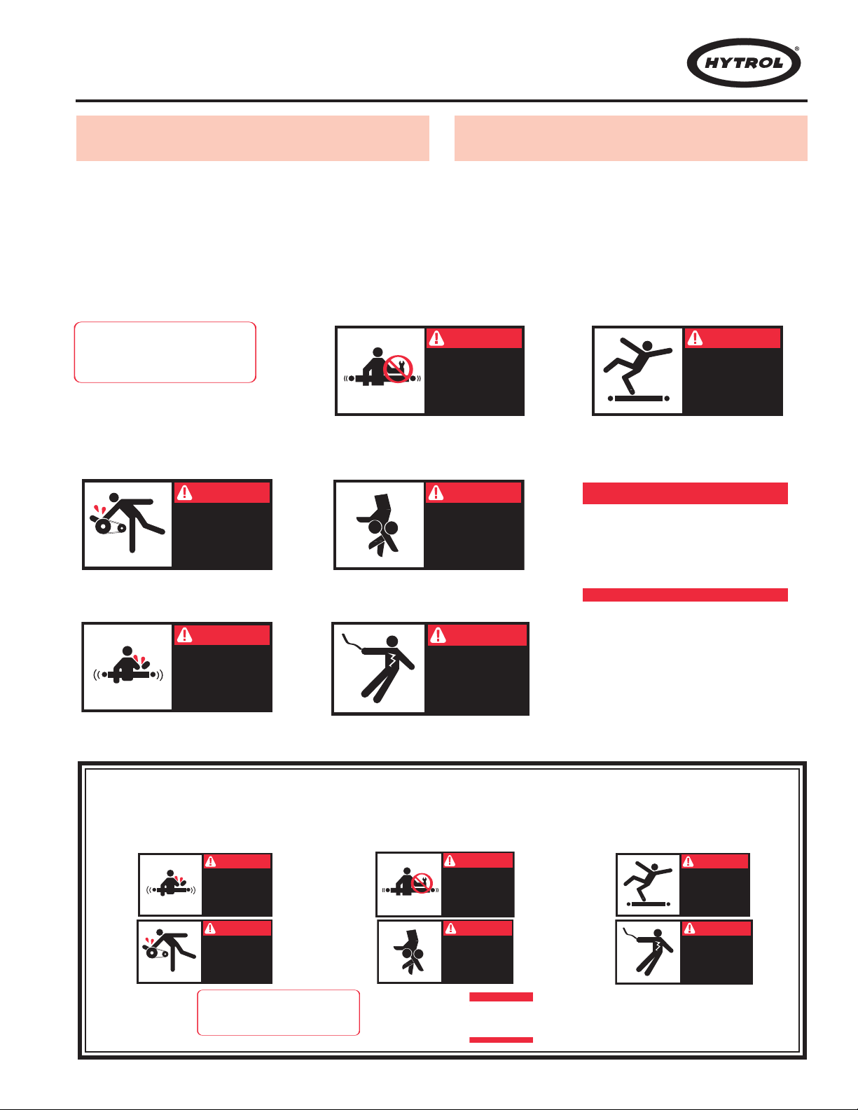
Señales de Advertencia
In an effort to reduce the possibility of injury to personnel
working around HYTROL conveying equipment, warning
signs are placed at various points on the equipment to alert
them of potential dangers. Please check equipment and
note all warning signs. Make certain your personnel are
alerted to and obey these warnings. Shown below are typical signs that are attached to this equipment.
PLACED ON ALL POWERED CONVEYORS
NEAR DRIVE AND/OR CONTROLS.
COLOCADA EN TODOS LOS
TRANSPORTADORES MOTORIZADOS
CERCA AL MOTOR Y/O LOS CONTROLES
PLACED ON ALL CHAIN GUARDS.
COLOCADA EN TODAS LAS GUARDACADENAS.
PLACED NEXT TO DRIVE, BOTH SIDES.
COLOCADA JUNTO A LA UNIDAD MOTRIZ, EN
AMBOS LADOS.
PLACED ON TERMINATING ENDS.
COLOCADA EN LOS EXTREMOS.
En un esfuerzo por reducir la posibilidad de accidentes al
personal trabajando junto al equipo de transportación
HYTROL, se colocan señales de advertencia en diferentes
puntos del equipo para alertarlos de riesgos potenciales.
Por favor verifique el equipo y asegúrese de ver todas las
señales de advertencia. Asegúrese de que su personal esté
alerta y obedezca las señales. Abajo se muestran las
señales que se encuentran en este equipo.
PLACED ON 20 FT. INTERVALS,BOTH SIDES.
COLOCADA EN INTERVALOS DE 20 PIES, AAMBOS LADOS.
PLACED AT DRIVE OF ALL POWERED CONVEYORS.
COLOCADA EN LAUNIDAD MOTRIZ DE TODOS LOS
TRANSPORTADORES MOTORIZADOS.
PLACED NEXT TO DRIVE, BOTH SIDES.
COLOCADA JUNTO A LA UNIDAD MOTRIZ, EN
AMBOS LADOS.
NOTE: BILINGUAL (SPANISH) LABELS AVAILABLE UPON REQUEST.
NOTA: ETIQUETAS BILINGÜES (ESPAÑOL) SERÁN PROVEÍDAS
BAJO PETICIÓN.
PLACED AT ALL ZONE BOXES
COLOCADA EN TODAS LAS ZONAS CON
MOTOR
3
INTRODUCTION
INTRODUCCION
This manual provides guidelines and procedures for
installing, operating, and maintaining your conveyor. A complete parts list is provided with recommended spare parts
highlighted in gray. Important safety information is also provided throughout the manual. For safety to personnel and
for proper operation of your conveyor, it is recommended
that you read and follow the instructions provided in this
manual.
l Receiving and
Uncrating
1. . .
Check the number of items received against the bill of
lading.
2. . .
Examine condition of equipment to determine if any
damage occurred during shipment.
3. . .
Move all crates to area of installation.
4. . .
Remove crating and check for optional equipment
that may be fastened to the conveyor. Make sure
these parts (or any foreign pieces) are removed.
Este manual provee las pautas y los procedimientos para
instalar, operar y mantener su transportador. Se proporciona una lista completa de partes, con partes de repuesto
recomendadas que se resaltan en gris. También se proporciona información importante de seguridad a lo largo de
este manual. Para seguridad del personal y para un funcionamiento apropiado del transportador, se recomienda
que lean y sigan las instrucciones proporcionadas en este
manual.
l
Recepción y Desembalaje
1. . .
Verifique el número de partes recibidas con respecto al
conocimiento de embarque.
2. . .
Examine las condiciones del equipo con el fin de determinar si algún daño ha ocurrido durante el transporte.
3. . .
Traslade todo el equipo al área de instalación.
4. . .
Remueva todos los empaques y verifique si hay partes
opcionales que puedan estar atadas al equipo.
Asegúrese de que estas partes (u otras partes externas) sean removidas.
NOTE: If damage has occurred or freight is missing, see
the “Important Notice” attached to the crate.
NOTA: Si algún daño ha ocurrido o falta cargamento,
vea las “Notas Importantes” adheridas al embalaje.
4

INSTALLATION
l
Installation Safety Precautions
for Conveyors and
INSTALACION
l
Medidas de Seguridad al Instalar
Transportadores y Equipos
Relacionados
Related Equipment
GUARDS AND GUARDING
Interfacing of Equipment. When two or more pieces of
equipment are interfaced, special attention shall be given to
the interfaced area to insure the presence of adequate
guarding and safety devices.
Guarding Exceptions. Wherever conditions prevail that
would require guarding under these standards, but such
guarding would render the conveyor unusable, prominent
warning means shall be provided in the area or on the
equipment in lieu of guarding.
Guarded by Location or Position. Where necessary for
the protection of employees from hazards, all exposed mov
ing machinery parts that present a hazard to employees at
their work station shall be mechanically or electrically guarded, or guarded by location or position.
When a conveyor passes over a walkway, roadway, or
work station, it is considered guarded solely by location or
position if all moving parts are at least 8 ft. (2.44 m) above
the floor or walking surface or are otherwise located so that
the employee cannot inadvertently come in contact with
hazardous moving parts.
Although overhead conveyors may be guarded by location, spill guard, pan guards, or equivalent shall be provided
if the product may fall off the conveyor for any reason and if
personnel would be endangered.
HEADROOM
When conveyors are installed above exit passageways,
aisles, or corridors, there shall be provided a minimum
clearance of 6 ft. 8 in. (2.032 m) measured vertically from
the floor or walking surface to the lowest part of the con
veyor or guards.
Where system function will be impaired by providing the
minimum clearance of 6 ft. 8 in. (2.032 m) through an emergency exit, alternate passageways shall be provided.
It is permissible to allow passage under conveyors with less
than 6 ft. 8 in. (2.032 m) clearance from the floor for other
than emergency exits if a suitable warning indicates low
headroom.
GUARDAS Y PROTECCIONES
Unión del Equipo. Cuando dos o más piezas del equipo
van unidas, debe ponerse especial atención al área de
unión para asegurar que las guardas adecuadas y los dispositivos de seguridad estén presentes.
Excepciones de Protección. Dondequiera que las
guardas sean necesarias, pero que la colocación de las
mismas inhabilite el uso del transportador
cionarán señales de advertencia visibles en el área o en el
equipo en vez de las guardas.
Protección dada por Posición o Ubicación. Cuando sea
necesaria la protección de los empleados contra posibles
riesgos, todas las partes del equipo que estén expuestas y
en movimiento, y que puedan presentar un peligro para
-
ellos en sus puestos de trabajo, serán protegidas mecánicamente o eléctricamente, o protegidas por su posición o
ubicación.
Cuando el transportador está instalado sobre pasillos,
corredores o puestos de trabajo, se considera que está protegido únicamente por localización o posición si todas las
partes en movimiento están mínimo a 8 pies (2.44m) de
altura del piso, o si está localizado de tal manera que el
empleado no pueda entrar en contacto inadvertidamente
con dichas partes.
A pesar de que los transportadores aéreos pueden estar
protegidos por localización, guardas laterales e inferiores
deben ser proporcionadas para evitar que el producto se
caiga del transportador y así mantener al personal fuera de
peligro.
UBICACION SUPERIOR
Cuando los transportadores son instalados sobre pasillos o
corredores de salida, debe dejarse un espacio libre de
-
mínimo 6 pies 8 pulgadas (2,032m), medido verticalmente
desde el piso o área de tránsito hasta la parte más baja del
transportador o de las guardas.
Si se proporcionan señales de advertencia adecuadas indicando baja altura, es posible dejar espacio libre con menos
de 6 pies 8 pulgadas (2.032m) entre el piso y el transportador en los pasillos que no sean salidas de emergencia.
, se propor-
5
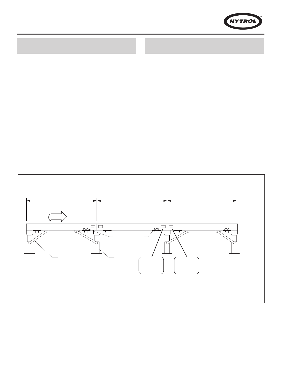
l Support Installation l
INFEED ZONE
FLOW
(ZONA DE ALIMENT ACION)
INTERMEDIATE ZONE
(ZONA INTERMEDIA)
"MATCH-MARK" NUMBERS
(ETIQUETAS DE SECUENCIA DE ARMADO)
DISCHARGE ZONE
(ZONA DE DESCARGA)
KNEE BRACE ANGLE
(ANGULO DE SOPORTE)
HYTROL CONVEYOR CO. INC.
JONESBORO, AR
MARK_______________________
CONVEYOR F.O.#_____________
ITEM___________TO___________
P-1
00001
12
HYTROL CONVEYOR CO. INC.
JONESBORO, AR
MARK_______________________
CONVEYOR F.O.#_____________
ITEM___________TO___________
P-1
00001
21
SUPPORTS
(SOPORTES)
EZL OGIC®
ZONE CONTROLL ER
(DIFFUSE SHOWN)
(CONTROLADOR DE ZONA EZLOGIC®)
[DIFUSO ES MOSTRADO]
1. . .
Determine direction of product flow. Figure 6A indicates the flow as related to the EZLogic®controls.
2. . .
Refer to “Match-Mark” numbers on ends of conveyor
sections. (Figure 6A.) Position them in this sequence
near area of installation.
3. . .
Attach supports to all conveyor sections as shown in
Figures 7A and 7B. Hand tighten bolts only at this
time.
4. . .
Adjust elevation to required height.
FIGURE 6A
1…Determine la dirección del flujo del producto. La Figura
2…Refiérase a las Etiquetas de Secuencia de Armado
3…Fije los soportes a todas las secciones de transporta-
4…Ajuste la elevación a la altura requerida.
Instalación de los Soportes
6A indica la dirección del flujo con relación a los controles EZLogic®.
ubicadas al final de las secciones del transportador
(Figura 6A). Posicione las secciones en esta secuencia cerca al área de instalación.
dor como se muestra en las figuras 7A
momento, puede apretar los tornillos manualmente.
y 7B. En este
6

S
UPPORT
(SOPORTE)
I
NTERMEDIATE
SUPPORTS
(SOPORTES
INTERMEDIOS)
A
DJUST TO DESIRED
ELEVATION
(
AJUSTE A LA ALTURA
DESEADA)
FIGURE 7A
BUTT COUPLINGS
(PLACAS DE EMPALME)
SIDE CHANNELS
(CANAL LATERAL)
PIVOT PLATE
(PLACA PIVOTE)
STATIONARY SUPPORT
(SOPORTE EST ACIONARIO)
MOUNTING BOLT
(TORNILLO DE MONT AJE)
SIDE CHANNEL
(CANAL LATERAL)
FIGURE 7B
7

l Conveyor Set-Up
1. . .
Mark a chalk line on floor to locate center of the conveyor.
2. . .
Place the infeed section in position.
3. . .
Place remaining sections on extended support of previous section.
4. . .
Fasten sections together with butt couplings and
pivot plates (Figure 7B). Hand tighten bolts only at
this time.
5. . .
Check to see that conveyor is level across width and
length of unit. Adjust supports as necessary.
6. . .
Tighten all butt couplings and support mounting bolts
and lag conveyor to floor.
7. . .
Connect EZLogic® cordset and EZDrive™ cable
(Fig. 9A).
8. . .
Install electrical controls and wire disconnect panel
(Figure 9B). The Dual Output Disconnect Panel
requires a 30 amp service and the Single Output Disconnect Panel requires a 15 amp service. All lines
must have proper Fuse or Breakers. See Disconnect
Panel for required voltage.
9. . .
Connect IOP to EZLogic®. See EZLogic® GEN3
Component Manual for more information about IOP.
Note! All drive roller shafts are turned to within 10 thousandths TIR (Total Indicator Runout). Some wobbling of
the gearmotor may be noticeable and is typical in Torque
Arm mounted gearmotors. This allows the gearmotor to
float which prevents fatiguing of the drive shaft or premature failure of bearing components.
l
Montaje del Transportador
1…Marque con tiza una línea en el suelo para ubicar el cen-
tro del transportador.
2…Coloque la sección de alimentación en su posición.
3…Coloque las secciones restantes en la placa pivote del
soporte de la sección anterior
4…Asegure las secciones con placas de empalme y placas
pivote (Figura 7B). Apriete los tornillos manualmente.
5…Revise si el transportador esta nivelado a lo ancho y
largo de la unidad. Ajuste los soportes como sea necesario.
6…Apriete las placas de empalme y los tornillos de montaje
del soporte y ancle el transportador al piso.
7…Conecte el cable del EZLogic®
(Figura 9A).
8…Instale los controles eléctricos y conecte el panel de con-
trol (Figura 9B). El panel de control de salida doble
requiere un servicio de 30 amperios. El panel de control
sencillo requiere un servicio de 15 amperios. Todas las
líneas deben tener fusibles o cortacircuitos apropiados.
Vea el panel de control para el voltaje requerido.
9…Conecte la IOP al EZLogic
nentes de EZLogic® para mayor información acerca del
IOP.
Nota! Todos los ejes motrices rotan alrededor de diez mil
TIR (Total Indicador Runout). Puede llegarse a notar un
balanceo del gearmotor y es típico en gearmotors montados en Brazos con Torque. Esto le permite al gearmotor
flotar lo cual previene la fatiga del eje motriz o el desgaste
prematuro de los componentes del rodamiento.
.
y el cable del EZDrive™
®
. Vea el manual de compo-
8
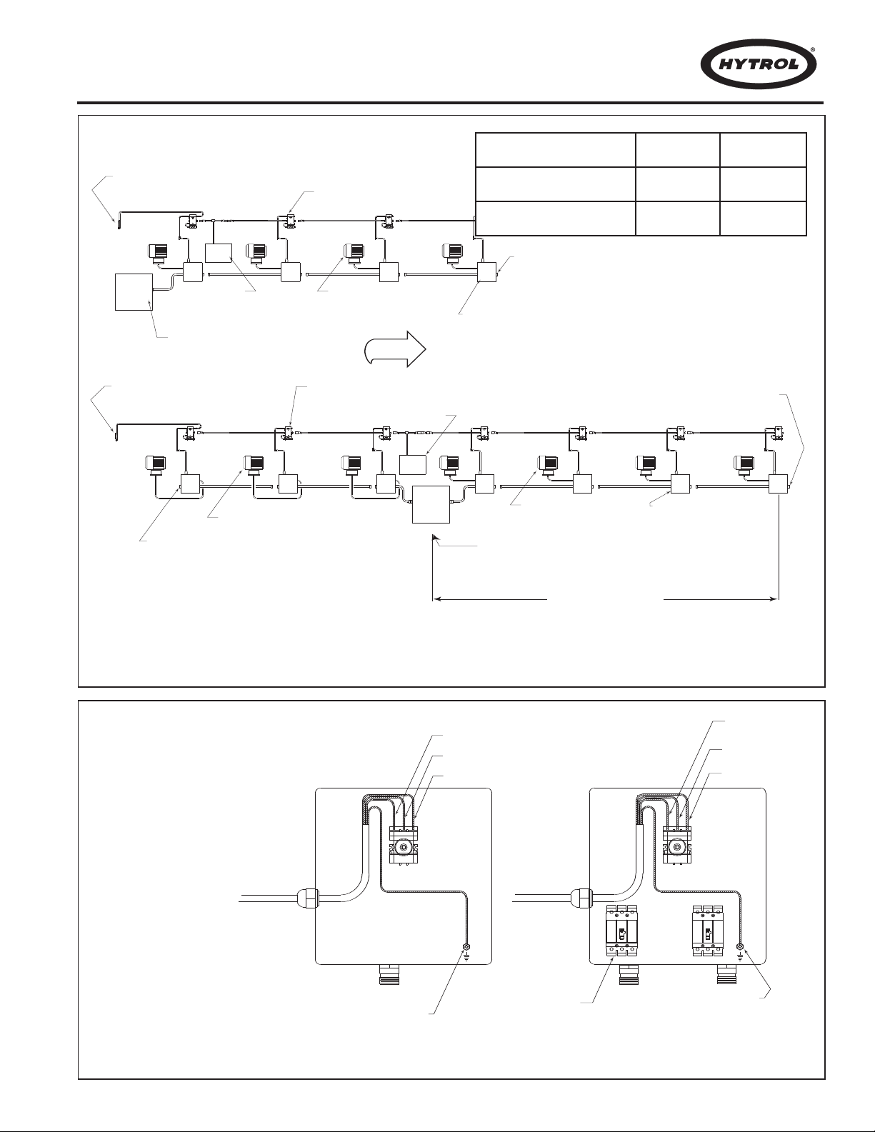
SINGLE OUTPUT DISCONNECT PANEL
(PANEL PRINCIPAL DE SALIDA UNICA)
Z
ONE GEARMOTOR
(MOTOR EN ZONA)
ZONE GEARMOTOR
(MOTOR EN ZONA)
EZDRIVE™ ZONE STARTER BOX
(CONTROLADOR DE ZONA EZDRIVE™)
ELECTRICAL END CAP
(
TAPON DE ULTIMA
CONEXION ELECTRICA)
ELECTRICAL END CAP
(TAPON DE ULTIMA
C
ONEXION ELECTRICA)
EZLOGIC® ZONE CONTROLLER
(MÓDULO DE ZONA EZLOGIC®)
DUAL OUTPUT DISCONNECT PANEL
(MUST BE LOCATED AT THE CENTER OF CONVEYOR)
E
LECTRICAL END CAP
(TAPON DE ULTIMA
CONEXION ELECTRICA)
50 FT. MAXIMUM DISTANCE
(
SEE CHART FOR NUMBER OF ZONES)
PANEL DE SALIDA DOBLE CON FUENTE DE PODER
(
DEBE SER UBICADA EN EL CENTRO DEL TRANSPORTADOR)
50 FT. DISTANCIA MÁXIMA
(VER CUADRO PARA EL NÚMERO DE ZONAS)
E
ZLOGIC® ZONE CONTROLLER
WAKE UP EYE
(MÓDULO DE ZONA EZLOGIC®
O
JO DESPERTADOR)
IOP
(IOP)
E
ZLOGIC® ZONE CONTROLLER
WAKE UP EYE
(MÓDULO DE ZONA EZLOGIC®
O
JO DESPERTADOR)
EZLOGIC® ZONE CONTROLLER
(MÓDULO DE ZONA EZLOGIC®)
I
OP
(IOP)
ZONE GEARMOTOR
(MOTOR EN ZONA)
E
ZDRIVE™ ZONE STARTER BOX
(CONTROLADOR DE
ZONA EZDRIVE™)
FLOW
L1
(L1)
L2
(L2)
L3
(L3)
GROUND
(CONEXION A TIERRA)
15A BREAKER
(DISYUNTOR DE 15A)
L1
(L1)
L2
(L2)
L3
(L3)
GROUND
(CONEXION A TIERRA)
FIGURE 9A
DISCONNECT PANEL
(PANEL DE CONTROL)
SINGLE OUTPUT
(PANEL DE SALIDA SENCILLO)
DUAL OUTPUT
(PANEL DE SALIDA DOBLE)
208/230V
3 PH. 60 HZ
1-5 ZONES
(1-5 ZONAS)
6-10 ZONES
(6-10 ZONAS)
460V
3 PH. 60 HZ
1-10 ZONES
(1-10 ZONAS)
11-20 ZONES
(11-20 ZONAS)
FIGURE 9B
NOTE: CUSTOMER MUST
SUPPLY 15 AMP OR 30 AMP
OVERCURRENT PROTECTION TO ALL DISCONNECT
PANELS.
(NOTA: EL CLIENTE DEBE
PROVEER UNA PROTECCIÓN
DE SOBRECARGA DE 14 AMP
O 30 AMPA TODOS LOS PANELES DE SALIDA)
SINGLE OUTPUT DISCONNECT PANEL
(PANEL PRINCIPAL DE SALIDA SENCILLO)
15 AMP
30 AMP
DUAL OUTPUT DISCONNECT PANEL
(PANEL PRINCIPAL DE SALIDA DOBLE)
9

l Electrical Equipment
l
Equipo Eléctrico
WARNING!
Electrical controls shall be installed and wired by a
qualified electrician. Wiring information for the motor
and controls are furnished by the equipment manufacturer.
CONTROLS
Electrical Code: All motor controls and wiring shall conform
to the National Electrical Code (Article 670 or other applica
ble articles) as published by the National Fire Protection
Association and as approved by the American Standards
Institute, Inc.
CONTROL ST
A) Control stations should be so arranged and located that
the operation of the equipment is visible from them, and
shall be clearly marked or labeled to indicate the function
controlled.
B) A conveyor which would cause injury when started shall
not be started until employees in the area are alerted by a
signal or by a designated person that the conveyor is about
to start.
When a conveyor would cause injury when started and
is automatically controlled or must be controlled from a
remote location, an audible device shall be provided which
can be clearly heard at all points along the conveyor where
personnel may be present.
actuated by the controller device starting the conveyor and
shall continue for a required period of time before the conveyor starts. Aflashing light or similar visual warning may be
used in conjunction with or in place of the audible device if
more effective in particular circumstances.
Where system function would be seriously hindered or
adversely affected by the required time delay or where the
intent of the warning may be misinterpreted (i.e., a work
area with many different conveyors and allied devices),
clear, concise, and legible warning shall be provided. The
warning shall indicate that conveyors and allied equipment
may be started at any time, that danger exists, and that personnel must keep clear. The warnings shall be provided
along the conveyor at areas not guarded by position or location.
C) Remotely and automatically controlled conveyors, and
conveyors where operator stations are not manned or are
beyond voice and visual contact from drive areas, loading
areas, transfer points, and other potentially hazardous loca
tions on the conveyor path not guarded by location, position,
or guards, shall be furnished with emergency stop buttons,
pull cords, limit switches, or similar emergency stop
devices.
All such emergency stop devices shall be easily identifi-
10
ATIONS
The warning device shall be
¡ADVERTENCIA!
Los controles eléctricos deben ser conectados e instalados por un electricista calificado. La información sobre
el cableado del motor y los controles será proporcionada
por el fabricante del equipo.
CONTROLES
Código Eléctrico: Todos los controles del motor y las
-
conexiones deben ajustarse al “
(Artículo 670 u otros artículos aplicables) como fué publicado
National Fire Protection Association”
por la “
“American Standards Institute, Inc”.
ESTACIONES DE CONTROL
A) Las estaciones de control deberán estar arregladas y ubi-
cadas en lugares donde el funcionamiento del equipo sea visible y deberán estar claramente marcadas o señaladas para
indicar la función controlada.
B) Un transportador que pueda causar lesiones cuando es
puesto en marcha, no deberá ponerse en funcionamiento
hasta que los trabajadores en el área sean alertados por una
señal o por una persona designada que indique que el transportador está a punto de arrancar.
Cuando un transportador pueda causar lesiones al arrancar y
es controlado automáticamente o controlado desde una ubicación lejana, se deberá proporcionar un dispositivo sonoro el
cual pueda ser escuchado claramente en todos los puntos a lo
largo del transportador donde el personal pueda estar presente. El dispositivo de advertencia deberá ser activado por el
dispositivo de arranque del transportador y deberá continuar
sonando por un determinado periodo de tiempo antes de que
el transportador empiece a funcionar
una advertencia visual similar puede ser utilizada con o en
lugar del dispositivo sonoro si es más efectivo en circunstancias particulares.
Cuando el funcionamiento del sistema pueda ser seriamente
obstruído o adversamente afectado por el tiempo de retardo
requerido, o cuando el intento de advertencia pueda ser mal
interpretado (ej., un área de trabajo con diversas líneas de
transportadores y los dispositivos de advertencia relacionados), advertencias claras, concisas y legibles deben ser proporcionadas. Las advertencias deberán indicar que los transportadores y los equipos relacionados pueden ser puestos en
marcha en cualquier momento, que existe un peligro y que el
personal debe mantenerse alejado. Estas advertencias deben
ser proporcionadas a lo largo del transportador en áreas que
-
no sean protegidas por la posición o la ubicación.
C) Los transportadores controlados automáticamente o desde
estaciones lejanas, y los transportadores donde las estaciones
de funcionamiento no estén controladas por una persona, o
estén mas allá del alcance de la voz y del contacto visual de
National Electrical Code”
y aprobado por el
. Una luz intermitente o

able in the immediate vicinity of such locations unless
guarded by location, position, or guards. Where the design,
function, and operation of such conveyor clearly is not hazardous to personnel, an emergency stop device is not
required.
The emergency stop device shall act directly on the control of the conveyor concerned and shall not depend on the
stopping of any other equipment. The emergency stop
devices shall be installed so that they cannot be overridden
from other locations.
D) Inactive and unused actuators, controllers, and wiring
should be removed from control stations and panel boards,
together with obsolete diagrams, indicators, control labels,
and other material which serve to confuse the operator
SAFETY DEVICES
A) All safety devices, including wiring of electrical safety
devices, shall be arranged to operate in a “Fail-Safe” man
ner, that is, if power failure or failure of the device itself
would occur, a hazardous condition must not result.
Emergency Stops and Restarts.
B)
be so arranged that, in case of emergency stop, manual
reset or start at the location where the emergency stop was
initiated, shall be required of the conveyor(s) and associated equipment to resume operation.
Conveyor controls shall
.
las áreas de conducción, áreas de carga, puntos de transferencia y otros sitios potencialmente peligrosos localizados
en la trayectoria del transportador que no tenga protección
por posición, ubicación o guardas, deberán ser equipados
con interruptores, cordones o interruptores de límite o dispositivos similares para paradas de emergencia.
Todos estos dispositivos de parada de emergencia deberán
ser fácilmente identificables en las cercanías inmediatas a
los puntos potencialmente peligrosos, a no ser que estén
protegidos por su ubicación, posición o protegidos con
guardas. Donde el diseño, el funcionamiento, y la operación
de tales transportadores no represente un claro peligro para
el personal, un dispositivo de parada de emergencia no es
necesario.
El dispositivo de parada de emergencia deberá actuar directamente en el control del transportador concerniente y no
deberá depender de la parada de cualquier otro equipo. Los
dispositivos de parada de emergencia deberán ser instalados de tal forma que no puedan ser anulados desde otras
-
localidades.
D) Los dispositivos, controles desactivados o en desuso y
las conexiones, deberán ser removidos de las estaciones de
control y de los tableros de mando, junto con los diagramas,
indicadores, etiquetas de control y otros materiales obsoletos, los cuales se prestan para confundir al operador
DISPOSITIVOS DE SEGURIDAD
.
C) Before restarting a conveyor which has been stopped
because of an emergency, an inspection of the conveyor
shall be made and the cause of the stoppage determined.
The starting device shall be locked out before any attempt
is made to remove the cause of stoppage, unless operation
is necessary to determine the cause or to safely remove the
stoppage.
Refer to
Personnel Protection – Lockout/Tagout of Energy Sources –
Minimum Safety Requirements and OSHA Standard Number 29 CFR 1910.147 “The Control of Hazardous Energy
(Lockout/Tagout).”
ANSI Z244.1-1982, American National Standard for
A) Todos los dispositivos de seguridad, incluyendo la conexión de dispositivos eléctricos, deben estar dispuestos
para operar en una manera de “autoprotección”; es decir, si
se presenta una pérdida de corriente o un fallo en el mismo
dispositivo, esto no debe resultar en una situación peligrosa.
B) Paradas de Emergencia y Reactivadores. Los controles
del transportador deberán estar dispuestos de tal manera
que, en caso de una parada de emergencia, se requiere un
activador o un arrancador manual en el lugar donde la parada de emergencia se presente para reanudar la operación
del transportador o transportadores y el equipo asociado.
C) Antes de reiniciar un transportador que ha sido detenido
por una emergencia, debe realizarse una revisión del transportador y determinarse la causa de la parada. El dispositivo de arranque deberá ser bloqueado antes de intentar corregir el problema, a no ser que la operación del transportador sea necesaria para determinar la causa de la parada o
para solucionar el problema.
Refiérase al
ANSI Z244.1-1982, American National Standard
for Personnel Protection - Lockout/T agout of Energy Sources
- Minimum Safety Requirements and OSHA Standard
Number 29 CFR 1910.147 “The Control of Hazardous
Energy (Lockout/Tagout).”
11

l Sequence of Operation l
Secuencia de Operación
The CREZD models are made up of a series of accumulation zones, each zone having an EZLogic® zone controller,
an EZDrive™ zone starter box and a gearmotor. The
sequence of "loading" and "unloading" the conveyor is as
follows:
LOADING THE CONVEYOR - SINGULATION MODE
(Figure 13A)
1. . .
Beginning with the conveyor "empty," and the zone
stop signal to the discharge zone controller
"active,"(Refer to the “Auxiliary Connections” section,
page 14.) a load placed on the conveyor continues
forward until it reaches the discharge zone (Zone #1).
If two or more loads are placed on the conveyor with
a space of less than one zone length between them,
the loads will singulate (separate) during the first few
feet of travel on the conveyor
mately equal to one zone length exists between all
loads.
2. . .
When load #1 activates zone controller "A", Zone #1
stops driving. A signal is sent to Zone #2 indicating
that Zone #1 is occupied (Figure 13A).
3. . .
When load #2 activates zone controller "B", Zone #2
stops driving. A signal is sent to Zone #3 indicating
that Zone #2 is occupied.
4. . .
The above sequences are repeated until the conveyor is fully loaded.
UNLOADING THE CONVEYOR - SINGULA
1. . .
Releasing load #1 is accomplished by "de-activating"
the zone stop signal to the discharge zone (Refer to
the "Auxiliary Connections" section on page 14). This
restores power to the tread rollers in zone #1. Load
#1 will then move forward, causing a gap between
itself and load #2 (Figure 13B).
2. . .
When load #1 clears zone controller "A", load #2 will
then move forward, creating a gap between itself and
load #3.
3. . .
This sequence will continue as long as the preceding
load continues to move forward.
, until a space approxi-
TION MODE
Los modelos CREZD están compuestos por una serie de
zonas de acumulación. Cada zona posee un módulo de
acumulación EZLogic®, un motor controlador EZDrive™ y
un gearmotor. La secuencia de "carga" y "descarga" del
transportador es como sigue:
CARGANDO EL TRANSPORTADOR –
SINGULA
1. . .
2. . .
3. . .
4. . .
DESCARGANDO EL TRANSPORTADOR –
MODO DE SINGULACIÓN
1. . .
2. . .
3. . .
TION MODE (Figura 13A)
Empezando con el transportador "vacío" y la señal de
paro "activa" (Refiérase a la sección de “conexiones
Auxiliares,” págiina 14.) en el módulo de la zona de
descarga, un primer producto puesto sobre el transportador hará el recorrido hasta que llegue a la zona
de descarga (Zona #1).
Si dos o más productos se colocan sobre el transportador con un espacio de separación entre ellos
menor que la longitud de una zona, los productos se
separarán durante los primeros pies de recorrido en
el transportador hasta que el espacio entre los productos sea por lo menos igual a la longitud de una
zona.
Cuando el producto #1 activa el módulo "A", la zona
#1 se detiene completamente. Una señal es enviada
a la zona #2 indicando que la zona #1 está ocupada
(Figura 13A).
Cuando el producto #2 activa el módulo "B", la zona
#2 se detiene completamente. Una señal es enviada
a la zona #3 indicando que la zona #2 está ocupada.
La secuencia anterior se repite hasta que el transportador esté completamente cargado.
Se logra liberar el producto #1 "desactivando" la
señal de paro en la zona de descarga. (Refiérase a
la sección “Conexiones de Paro de Zona” en la página 14.) De esta forma se restablece la tracción en
los rodillos de paso en la zona #1. El producto #1 se
moverá hacia adelante, causando un espacio entre si
mismo y el producto #2 (Figura 13B).
Cuando el producto #1 despeja el módulo "A", el producto #2 se moverá hacia adelante creando un espacio entre si mismo y el producto #3.
Esta secuencia continuará mientras los productos
precedentes continúen moviéndose hacia adelante.
12
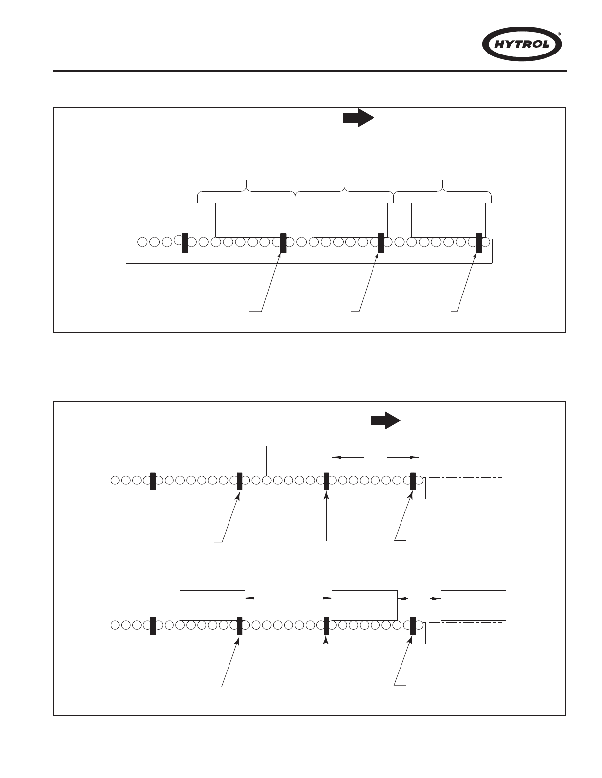
CARTON #3
(CAJA #3)
CARTON #2
(CAJA #2)
CARTON #1
(CAJA #1)
CARTON #3
(CAJA #3)
CARTON #2
(CAJA #2)
CARTON #1
(CAJA #1)
GAP
GAP
GAP
(ESPACIO)
CONTROLLER "C"
(
MÓDULO
"C")
CONTROLLER "B"
(
MÓDULO
"B")
CONTROLLER "A"
(
MÓDULO
"A")
FLOW
(FLUJO)
CONTROLLER "C"
(
MÓDULO
"C")
CONTROLLER "B"
(
MÓDULO
"B")
CONTROLLER "A"
(
MÓDULO
"A")
(ESPACIO) (ESPACIO)
CARTON #3
(CAJA #3)
CARTON #2
(CAJA #2)
CARTON #1
(CAJA #1)
ZONE #3
(ZONA)
ZONE #2
(ZONA)
(FLUJO)
ZONE #1
(ZONA)
FLOW
CONTROLLER "C"
(MÓDULO "C")
CONTROLLER "B"
(MÓDULO "B")
CONTROLLER "A"
(MÓDULO "A")
FIGURE 13A
FIGURE 13B
13

l EZLogic®System l
Sistema EZLogic
®
EZLogic®Accumulation System Connections
The CREZD models are equipped with the EZLogic®accumulation system. The following basic information may be used as
a guide during the installation and initial setup of the conveyor.
For detailed information about EZLogic®system components,
options, functions, and programming, please refer to the
EZLogic
®
GEN3 Component Manual.
Each EZLogic®zone controller is equipped with sealed connectors for zone-to-zone communication, solenoid output, and
zone stop connections (Figure 15B). These connections are
described in the following sections.
ZONE CONNECTIONS
Each zone controller has a cordset terminated with a female
micro-connector and a male micro-connector
. This cordset provides power to all the zone controllers on the conveyor as well
as communication between zone controllers (Figure 15A).
All zone controllers are mounted and connected at the factory
within each conveyor section. Connections between sections
are made at installation. (See Conveyor Set-Up, page 8). The
cordset from one zone controller is always connected to the
cordset on the upstream side of it. This is the way the zone
controllers know which direction product is flowing.
The cordset on the infeed end of the conveyor is simply bundled and tied in the accumulation channel and is not connected. The infeed cordset may be replaced with an infeed zone
terminator (P/N 032.550). Protective caps are provided to seal
unused connectors.
An optional conveyor-to-conveyor connector is required when
two conveyors are joined end-to-end. Please refer to the
EZLogic
®
GEN3 Component Manual for more information.
EZDrive™ CONNECTIONS
Each zone controller has a built-in run enable output cable to
provide a zone drive/no drive output to the EZDrive™ zone
starter box operating the zone (see figure 15B).
This cable is
terminated with a female pico-style sealed snap-lock connector. Connection is made by pushing the cable connector onto
the corresponding male connector of the zone starter box until
it snaps in.
Please note that this output is only to be used to operate the
zone mechanism of the conveyor. It is not to be used as an output signal to other control devices. If a control output is needed, an optional auxiliary I/O module should be used. Please
refer to the EZLogic
®
GEN3 Component Manual for more infor-
mation.
AUXILIARY CONNECTIONS
Every EZLogic“ zone controller is equipped with an auxiliary
port to accept a zone stop signal, a slug input signal, or a zone
wake-up signal by simply connecting an auxiliary input cable to
the auxiliary port of the controller and then wiring the two wires
of the cable to any “dry contact” type switching device, such as
a toggle switch or relay
. No other components are required.
The default setting is for a zone stop signal. To use the signal
for slug input or zone wake-up, program the zone controller as
detailed in the EZLogic“ Gen 3 Component Manual.
Note: Do not apply a voltage to these wires, or wire more than
14
Conexiones del Sistema de Acumulación EZLogic
El Modelo CREZD está equipado con un sistema de acumulación
EZLogic
®
. La siguiente información básica puede ser usada como
®
guía durante la instalación y el montaje del transportador. Para
información más detallada sobre los componentes del sistema
EZLogic
"Manual de Componentes EZLogic
Cada módulo EZLogic
®
, sus opciones, funciones, y programación, refiérase al
®
está equipado con conectores sellados que
®
".
permiten la comunicación zona-a-zona, con salida solenoide y con
conexiones de paro de zona (Fig.
15B
). Estas conexiones se
describen a continuación.
CONEXIONES DE ZONA
Cada módulo posee un micro-conector macho integrado en su
interior y un cable terminado con un micro-conector hembra. Este
cable transmite potencia a todos los módulos en el transportador y
también comunicación entre los módulos (Fig. 15A).
Todos los módulos son montados y conectados en la fábrica, en
cada sección del transportador
. Las conexiones entre las secciones se hacen durante la instalación (Ver Montaje, página 8). El
cable de un módulo debe ser conectado siempre al módulo de la
sección anterior. De esta forma los módulos reconocen la dirección del flujo de los productos.
El cable del módulo en la zona de alimentación del transportador,
debe ir simplemente amarrado al canal y no será conectado. El
cable de la zona de alimentación puede reemplazarse con un terminador de zona de carga (PN 032.550). Se proporcionan capas
protectoras para sellar los conectores que no se utilicen.
Cuando se van a conectar dos transportadores contiguos, se
requiere un conector transportador-transportador opcional.
Refiérase al "Manual de Componentes EZLogic
®
" para mayor infor-
mación.
CONEXIONES DEL EZDRIVE™
Cada módulo de acumulación posee un cable incorporado que
provee una señal de tracción/no-tracción al controlador EZDrive™
que opera la zona. (V
er Figura 15B.)
Este cable termina con un conector hembra sellado, "Pico-style",
que cierra a presión. La conexión se hace presionando el cable
conector al conector macho correspondiente del motor controlador
hasta que cierre completamente. Recuerde que esta señal debe
ser usada solo para operar el mecanismo de la zona del transportador. No debe ser usada como una señal de salida a otros dispositivos de control. Si se requiere una señal de control, se debe
usar un módulo de acumulación con I/O opcional. Por favor
refiérase al "Manual de Componentes EZLogic
®
" para mayor infor-
mación.
CONEXIONES AUXILIARES
®
Cada controlador de zona EZLogic
está equipado con un puerto
auxiliar. Este conector puede ser usado para aceptar, ya sea
una señal de paro de zona, una señal de entrada continua (slug),
o una señal de activación de zona, simplemente conectando el
cable de entrada auxiliar al puerto auxiliar y después conectando
los dos cables a cualquier dispositivo interruptor, como de palanca
o relevador (tipo “dry contact”). No se requieren más componentes.
El ajuste estándar es para señal de paro de zona. Para usar la
señal de entrada continua (slug) o la señal de activación de zona,
programe los controladores de zona según lo descrito en el
“EZLogic® Component Manual”
Nota: No aplique voltaje a estos cables o conecte más de un con-
 Loading...