

Page 1
IMPORTANT!
DO NOT DESTROY
¡IMPORTANTE!
NO DESTRUIR
Installation
and
Maintenance
Manual
with Safety Information
and Parts List
RECOMMENDED SPARE PARTS HIGHLIGHTED IN GRAY
Model ProSort 100 Elite
Manual
de Instalación
y
Mantenimiento
con Información sobre Seguridad
y Lista de Refacciones
LAS REFACCIONES RECOMENDADAS SE RESALTAN EN GRIS
May 2017
(Supersedes August 2000)
Bulletin #695
HYTROL | Jonesboro, Arkansas
© COPYRIGHT PENDING–HYTROL CONVEYOR CO., INC.
PRESS OPTIMIZED FOR THE ENVIRONMENT
(IMPRESIÓN OPTIMIZADA PARA PROTEGER EL MEDIO AMBIENTE)
Page 2
TABLE OF CONTENTS
Hytrol Conveyor
Company, Inc.
JONESBORO, ARKANSAS
SERIAL # 123456
YEAR
QR
CODE
INTRODUCTION
INTRODUCTION
Receiving and Uncrating ........................2
How to Order Replacement Parts .................2
SAFETY INFORMATION .............................3
INSTALLATION
Location .....................................4
Conveyor Set-Up ..............................4
Electrical Equipment............................5
OPERATION
Conveyor Start-Up .............................5
MAINTENANCE
Lubrication ...................................6
Oiler Brush Adjustment..........................6
Controlling the ProSort......................6, 7, 8
Pneumatic Divert Switch Checklist.................8
Electric Divert Switch Checklist ...................8
Carrying Chain Installation.......................9
Install Guard Rails at Divert Locations..............9
Locating the Spurs .............................9
Pneumatic Divert Switch Removal Procedure .......10
Electric Divert Switch Removal Procedure..........10
Electric Switch Homing Procedure................10
Trouble Shooting .............................11
Maintenance Checklist .................Back Cover
REPLACEMENT PARTS
Lost Pin Prox Assembly
Parts Drawing & List...........................11
Pneumatic Divert Switch Assembly
Parts Drawing & List...........................12
Electric Divert Switch Assembly
Parts Drawing & List...........................13
Safety Switch Assembly
Parts Drawing & List...........................13
ProSort 131 Parts Drawings
Catenary Divert, Return Divert, & Drive Section .....14
Intermediate Divert & Tail Section ................15
Induction Unit . . . . . . . . . . . . . . . . . . . . . . . . . . . . . . . .16
Intermediate Section Assembly ..................17
30° Divert Section.............................17
ProSort 131 Parts List ......................18, 19
ProSort 121 Parts Drawings
Catenary Divert, Return Divert, & Drive Section .....20
Intermediate Divert & Tail Section ................21
Induction Unit . . . . . . . . . . . . . . . . . . . . . . . . . . . . . . . .22
Intermediate Section Assembly ..................23
22° Divert Section.............................23
ProSort 121 Parts List ......................24, 25
ProSort 132 Parts Drawings
Catenary Divert & Drive Section .................26
Dual Divert & Divert Return .....................27
Dual Divert Return Switch & Tail .................28
Induction Unit . . . . . . . . . . . . . . . . . . . . . . . . . . . . . . . .29
ProSort 132 Parts List ......................30, 31
ProSort 122 Parts Drawings
Catenary Divert & Drive Section .................32
Dual Divert & Divert Return .....................33
Dual Divert Return Switch & Tail .................34
Induction Unit . . . . . . . . . . . . . . . . . . . . . . . . . . . . . . . .35
ProSort 122 Parts List ......................36, 37
Spanish Version ......................38
This manual provides guidelines and procedures for installing,
operating, and maintaining your conveyor. A complete parts list
is provided with recommended spare parts highlighted in gray.
Important safety information is also provided throughout the manual.
For safety to personnel and for proper operation of your conveyor, it
is recommended that you read and follow the instructions provided
in this manual.
• Receiving and Uncrating
1. Check the number of items received against the bill of lading.
2. Examine condition of equipment to determine if any damage
occurred during shipment.
3. Move all crates to area of installation.
4. Remove crating and check for optional equipment that may be
fastened to the conveyor. Make sure these parts (or any foreign
pieces) are removed.
NOTE: If damage has occurred or freight is missing,
Contact your Hytrol Integration Partner.
• How to Order Replacement Parts
Included in this manual are parts drawings with complete replacement
parts lists. Minor fasteners, such as nuts and bolts, are not included.
When ordering replacement parts:
1. Contact Dealer from whom conveyor was purchased or nearest
HYTROL Integration Partner.
2. Give Conveyor Model Number and Serial Number or HYTROL
Factory Order Number.
3. Give Part Number and complete description from Parts List.
4. If you are in a breakdown situation, tell us.
HYTROL Serial Number
(Located near Drive on Powered Models).
2
Page 3

SAFETY INFORMATION
• Installation
GUARDS AND GUARDING
Interfacing of Equipment. When two or more pieces of equipment
are interfaced, special attention shall be given to the interfaced area
to insure the presence of adequate guarding and safety devices.
Guarding Exceptions. Whenever conditions prevail that would
require guarding under these standards, but such guarding would
render the conveyor unusable, prominent warning means shall be
provided in the area or on the equipment in lieu of guarding.
Guarded by Location or Position. Where necessary for the
protection of employees from hazards, all exposed moving machinery
parts that present a hazard to employees at their work station shall
be mechanically or electrically guarded, or guarded by location or
position.
• Remoteness from frequent presence of public or employed
personnel shall constitute guarding by location.
• When a conveyor passes over a walkway, roadway, or work
station, it is considered guarded solely by location or position
if all moving parts are at least 8 ft. (2.44 m) above the oor or
walking surface or are otherwise located so that the employee
cannot inadvertently come in contact with hazardous moving
parts.
• Although overhead conveyors may be guarded by location, spill
guards, pan guards, or equivalent shall be provided if the product
may fall off the conveyor for any reason and if personnel would
be endangered.
HEADROOM
• When conveyors are installed above exit passageways, aisles,
or corridors, there shall be provided a minimum clearance of 6
ft. 8 in. (2.032 m) measured vertically from the oor or walking
surface to the lowest part of the conveyor or guards.
• Where system function will be impaired by providing the
minimum clearance of 6 ft. 8 in. (2.032 m) through an emergency
clearance, alternate passageways shall be provided.
• It is permissible to allow passage under conveyors with less
than 6 ft. 8 in. (2.032 m) clearance from the oor for other than
emergency exits if a suitable warning indicates low headroom.
• Operation
A) Only trained employees shall be permitted to operate conveyors.
Training shall include instruction in operation under normal conditions
and emergency situations.
B) Where employee safety is dependent upon stopping and/or
starting devices, they shall be kept free of obstructions to permit
ready access.
C) The area around loading and unloading points shall be kept clear
of obstructions which could endanger personnel.
H) Routine inspections and preventive and corrective maintenance
programs shall be conducted to insure that all safety features and
devices are retained and function properly.
I) Personnel should be alerted to the potential hazard of entanglement
in conveyors caused by items such as long hair, loose clothing, and
jewelry.
J) Conveyors shall not be maintained or serviced while in operation
unless proper maintenance or service requires the conveyor to be in
motion. In this case, personnel shall be made aware of the hazards
and how the task may be safely accomplished.
K) Owners of conveyor should insure proper safety labels are afxed
to the conveyor warning of particular hazards involved in operation of
their conveyors.
CAUTION! Because of the many moving parts on the conveyor, all
personnel in the area of the conveyor need to be warned that the conveyor
is about to be started.
• Maintenance
• All maintenance, including lubrication and adjustments, shall be
performed only by qualied and trained personnel.
• It is important that a maintenance program be established to
insure that all conveyor components are maintained in a condition
which does not constitute a hazard to personnel.
• When a conveyor is stopped for maintenance purposes, starting
devices or powered accessories shall be locked or tagged out
in accordance with a formalized procedure designed to protect
all persons or groups involved with the conveyor against an
unexpected start.
• Replace all safety devices and guards before starting equipment
for normal operation.
• Whenever practical, DO NOT lubricate conveyors while they are
in motion. Only trained personnel who are aware of the hazard of
the conveyor in motion shall be allowed to lubricate.
Safety Guards
Maintain all guards and safety devices IN POSITION and IN SAFE
REPAIR.
Safety Labels
In an effort to reduce the possibility of injury to personnel working
around HYTROL conveying equipment, safety labels are placed at
various points on the equipment to alert them of potential hazards.
Please check equipment and note all safety labels. Make certain
your personnel are alerted to and obey these warnings. See Safety
Manual for examples of warning labels.
REMEMBER Do not remove, reuse or modify material handling equipment
for any purpose other than it’s original intended use.
D) No person shall ride the load-carrying element of a conveyor
under any circumstances unless that person is specically authorized
by the owner or employer to do so. Under those circumstances, such
employee shall only ride a conveyor which incorporates within its
supporting structure platforms or control stations specically designed
for carrying personnel. Under no circumstances shall any person ride
on any element of a vertical conveyor.
E) Personnel working on or near a conveyor shall be instructed as to
the location and operation of pertinent stopping devices.
F) A conveyor shall be used to transport only material it is capable
of handling safely.
G) Under no circumstances shall the safety characteristics of the
conveyor be altered if such alterations would endanger personnel.
3
Page 4
INSTALLATION
FLOW
MATCH MARK NUMBERS
(ETIQUETAS DE SCUENCIA DE ARMADO)
KNEEBRACE
(SOPORTE ANGULAR)
INTERMEDIATE SUPPORT
(SOPORTE INTERMEDIOS)
DRIVE SUPPORT
(SOPORTE MOTRIZ)
DRIVE
(MOTOR)
CATENARY DIVERT
(DESVIACION CATENARIA)
RETURN DIVERT
(DESVIACION DE RETORNO)
INTERMEDIATE DIVERT
(DESVIACION INTERMEDIA)
TAIL
(RETORNO)
INFEED BELT DRIVE
(BANDA ALIMENTADORA
MOTRIZ)
INFEED INDUCTION BELT
(BANDA ALIMENTADORA DE INDUCCION)
5D
5A
4D
5B
4C 4E
4B 5C
FO:
MARK:
TOOL BOX
QR
CODE
H
Y
T
R
O
L
C
O
D
E
MODEL
A
FO:
MARK:
TOOL BOX
QR
CODE
H
Y
T
R
O
L
C
O
D
E
MODEL
A
(FLUJO)
BEARING PROFILE
BEARING PROFILE
JOINT
(SECCION DE UNION)
(PERFIL DEL
COJINETE)
(PERFIL DEL
COJINETE)
• Location
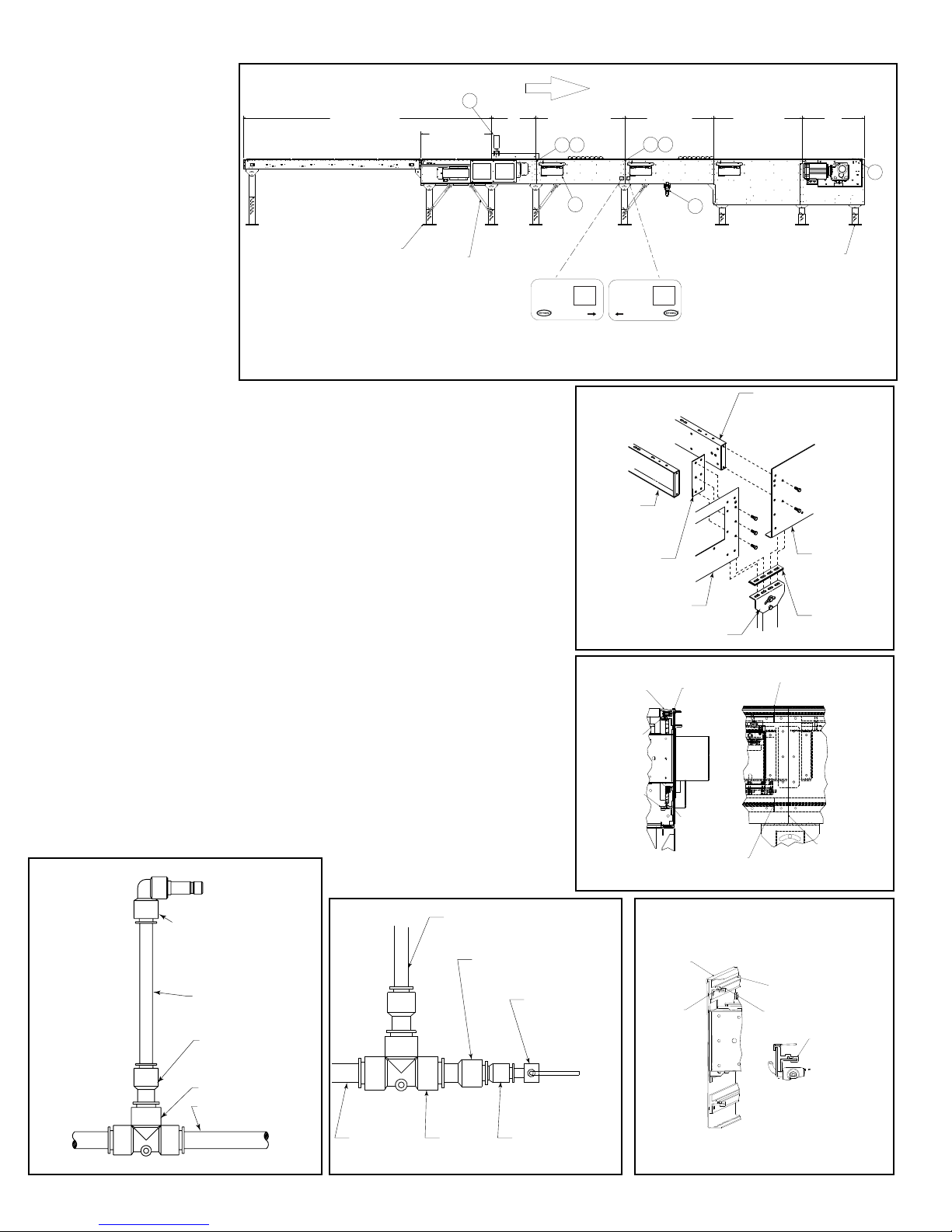
1. Determine direction of product flow.
FIGURE 4A
Figure 4A indicates the flow as related
to the drive.
2. Refer to “Match-Mark” numbers on
ends of conveyor sections. (Figure 4A).
Position them in this sequence near
area of installation.
• Conveyor Set-Up
1. Mark a chalk line on floor to locate
center of the conveyor.
2. Attach supports and vibration pads to
all conveyor sections shown in Figures
4A and 4B. Adjust elevation to required
height. Hand tighten bolts only at this
time.
3. During installation, check to make
sure each bed section is square.
Measure the diagonals from corner to
corner of the frame. If they are not equal
the frame must be squared. Attach a
come-along or some other suitable pulling device across longest corners and pull until the section is
square.
4. Place the infeed (tail) section in position.
5. Install remaining sections, placing end without support on extended pivot plate of previous section
(Figure 4A).
6. Fasten sections together with splice plates and pivot plates. (Figure 4B).
7. Check to see that conveyor is level across the width and length of unit. Adjust supports as necessary.
8. After all sections have been squared and levelled, tighten all splice channels and support mounting
bolts and lag support to the floor.
9. Check alignment of wearstrip at all section joints. Sand wearstrip as necessary to provide a smooth
wear surface (Figure 4C).
10. Starting on the infeed end, fasten bearing profile to wearstrip guide using rubber mallet to force the
profile edge under the wearstrip (Figure 4C & 4F). Glue infeed end of profile to the support angle with
loctite # 401 or 454 adhesive.
11. Run 1/2” main air line the full length of the sorter, either on the outside attaching it to the bottom of
conveyor channel with cable ties, or through the bed spacer holes where rubber grommets are provided
on the inside of the channel. (Figure 4A). Connect 3/8”air lines at divert switches as shown in Figures
4D & 4E.
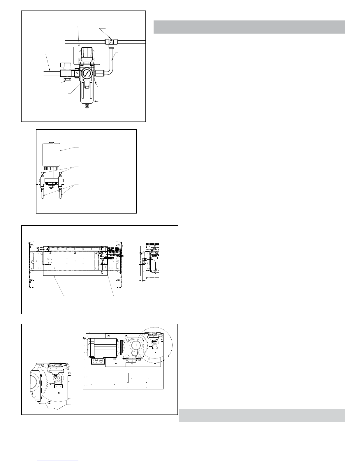
12. Connect main air line to the Filter/Regulator, (Figure 5A) Set regulator to working pressure of 60 P.S.I.
Install low pressure switch, at farthest point from regulator (Figure 4E).
13. Install electrical controls and wire motor. Verify correct motor rotation at this time. See Page 5 & 6 for
electrical control information.
14. Check each divert switch to see that it is operating properly. This must be done before carrying chains
are installed. See instructions on Page 8 & 9.
15. Check proximity switch clearance at each internal safety switch (Figure 5C). Adjust if necessary.
16. Install carrying chains per instructions on Page 8 & 9.
17. Install chain oiler at infeed and connect to oil lines as shown in Figure 5B. Refer to the Lubrication
section, page 6, for type of oil required. After mounting, the oiler will need to be adjusted for proper oiling
of mounting chains. Adjustment may be made using a combination of solenoid activation time and flow
adjustment screws. (A good rule of thumb for solenoid adjustment is to turn the oiler on for one complete
chain revolution for every 40 hours of sorter operation.) Typically, the chain on the divert side will need
slightly more oil; the flow adjustment screws can be altered to achieve volume. CAUTION: Do not allow
oil to drip on floor.
18. Locate spurs per instructions on Page 9.
INTERMEDIATE
SWITCHES
(INTERRUPTORES
INTERMEDIOS)
3/8" FEMALE TO 3/8" MALE
QUICK CONNECT FITTING
PLUG INTO VALVE
(HEMBRA DE 3/8" A MACHO DE 3/8"
DE RAPIDA CONEXION A VALVULA)
3/8" LINE
(LINEA DE 3/8")
FIGURE 4D
1/2" to 3/8" REDUCER
(REDUCTOR DE 1/2" A 3/8")
1/2" TEE
(TE DE 1/2")
1/2" MAIN LINE
(LINEA PRINCIPAL DE 1/2")
FIGURE 4E
MAIN AIR
(LINEA PRINCIPAL
DE AIRE)
LINE TO VALVE
(LINEA A LA VALVULA)
1/2" TO 3/8" REDUCER
(REDUCTOR DE 1/2" A 3/8")
1/2" TEE
(TE DE 1/2")
4
FIGURE 4B
FIGURE 4B
BED SPACER
(ESPACIADOR
FIGURE 4C
CHAIN COVER
(CUBIERTA DE
CADENA )
PRESSURE SWITCH
PRE SET AT 48 PSI
(INTERRUPTOR DE
PRESION AJUSTADO
A 48 PSI)
3/8" TO 1/4" REDUCER
(REDUCTOR DE 3/8" A 1/4")
DE CAMA)
(EMPALME)
(CANAL LATERAL)
SPLICE
SIDE CHANNEL
PIVOT PLATE
(PLACA PIVOTE)
FIGURE 4F
CHAIN COVER
(CUBIERTA DE
CADENA)
CHAIN GUIDE
MOUNTING ANGLE
(SECCION DE UNION)
BED SPACER
(ESPACIADOR DE CAMA)
UHMW WEARSTRIP
(TIRA DE DESGASTE
UHMW)
UHMW
WEARSTRIP
(TIRA DE DESGASTE
UHMW)
CHAIN GUIDES
OVERLAP JOINT
(JUNTA DE RECUBRIMIENTO
DE GUÍAS DE CADENA)
SIDE CHANNEL
(CANAL LATERAL)
VIBRATION PAD
(PROTECTORES
DE VIBRACION)
CHAIN GUIDES OVERLAP
(JUNTA DE RECUBRIMIENTO
DE GUÍAS DE CADENA)
SECTION JOINT
CHAIN GUIDE WEARSTRIP
(TIRA DE DESGASTE DE
GUÍA DE CADENA)
BEARING PROFILE
(PERFIL DEL COJINETE)
FORCE BEARING
PROFILE UNDER
WEARSTRIP
(FUERCE EL PERFIL DEL
COJINETE DEBAJO DE
LA TIRA DE DESGASTE)
Page 5
(SUMINISTRO
FIGURE 5A
TE
MOUNTING BRACKET
(FASTEN TO
CONVEYOR CHANNEL)
(PLACA DE MONTAJE
[SUJETAR AL CANAL
DEL TRANSPORTADOR])
MAIN AIR
SUPPLY
LINE
PRINCIPAL
DE AIRE)
LOCK-OUT VALVE
(VÁLVULA DE BLOQUEO)
GAUGE
(MEDIDOR)
FIGURE 5C
1/2" UNION TEE
(UNION TE DE 1/2")
AIR SUPPLY TO
AIR VALVES
(SUMINISTRO DE
AIRE A LAS
VALVULAS)
FILTER/REGULATOR
(REGULADOR/FILTRO)
BOWL GUARD
(TAZON PROTECT OR)
FIGURE 5B
OIL CUP
(RECIPIENTE
DE ACEITE)
ADJUSTMENT SCREWS
(TORNILLOS DE AJUSTE)
OIL LINES TO BRUSHES
(LINEAS DE ACEITE
PARA LAS BROCHAS)
• Electrical Equipment
WARNING! Electrical controls shall be installed and wired by a qualied electrician. Wiring information
for the motor and controls are furnished by the equipment manufacturer.
CONTROLS
Electrical Code: All motor controls and wiring shall conform to the National Electrical Code (Article 670
or other applicable articles) as published by the National Fire Protection Association and as approved
by the American National Standards Institute.
CONTROL STATIONS
A) Control stations should be so arranged and located that the operation of the equipment is visible
from them, and shall be clearly marked or labeled to indicate the function controlled.
B) A conveyor which would cause injury when started shall not be started until employees in the area
are alerted by a signal or by a designated person that the conveyor is about to start.
When a conveyor would cause injury when started and is automatically controlled or must be
controlled from a remote location, an audible device shall be provided which can be clearly heard at all
points along the conveyor where personnel may be present. The warning device shall be actuated by
the controller device starting the conveyor and shall continue for a required period of time before the
conveyor starts. A flashing light or similar visual warning may be used in conjunction with or in place
of the audible device if more effective in particular circumstances.
Where system function would be seriously hindered or adversely affected by the required time
delay or where the intent of the warning may be misinterpreted (i.e., a work area with many different
conveyors and allied devices), clear, concise, and legible warning shall be provided. The warning shall
indicate that conveyors and allied equipment may be started at any time, that danger exists, and that
personnel must keep clear. The warnings shall be provided along the conveyor at areas not guarded
by position or location.
C) Remotely and automatically controlled conveyors, and conveyors where operator stations are
not manned or are beyond voice and visual contact from drive areas, loading areas, transfer points,
and other potentially hazardous locations on the conveyor path not guarded by location, position,
or guards, shall be furnished with emergency stop buttons, pull cords, limit switches, or similar
emergency stop devices.
All such emergency stop devices shall be easily identifiable in the immediate vicinity of such
locations unless guarded by location, position, or guards. Where the design, function, and operation
of such conveyor clearly is not hazardous to personnel, an emergency stop device is not required.
The emergency stop device shall act directly on the control of the conveyor concerned and shall
not depend on the stopping of any other equipment. The emergency stop devices shall be installed so
that they cannot be overridden from other locations.
D) Inactive and unused actuators, controllers, and wiring should be removed from
control stations and panel boards, together with obsolete diagrams, indicators, control
labels, and other material which serve to confuse the operator.
SWITCH SENSOR
(INTERRUPTOR
DEL SENSOR)
FIGURE 5D
TRANSITION ASSEMBLY
DETAIL
(DETALLE DE CONJUNTO
DE TRANSICIÓN)
PROXIMITY SWTICH
(INTERRUPTOR DEL
PROXIMIDAD)
1/8"-3/16" FROM PROX
FACE TO METAL PLA
(1/8" - 3/16" DESDE LA
SUPERFICIE DE
PROXIMIDAD HASTA
LA PLACA METÁLICA)
L
SAFETY DEVICES
A) All safety devices, including wiring of electrical safety devices, shall be arranged
to operate in a “Fail-Safe” manner, that is, if power failure or failure of the device itself
would occur, a hazardous condition must not result.
B) Emergency Stops and Restarts. Conveyor controls shall be so arranged that, in
case of emergency stop, manual reset or start at the location where the emergency
stop was initiated, shall be required of the conveyor(s) and associated equipment to
resume operation.
C) Before restarting a conveyor which has been stopped because of an emergency,
an inspection of the conveyor shall be made and the cause of the stoppage
determined. The starting device shall be locked out before any attempt is made to
remove the cause of stoppage, unless operation is necessary to determine the cause
or to safely remove the stoppage.
Refer to ANSI Z244.1, American National Standard for Personnel Protection –
Lockout/Tagout of Energy Sources – Minimum Safety Requirements and OSHA
Standard Number 29 CFR 1910.147 “The Control of Hazardous Energy (Lockout/
Tagout).”
OPERATION
• Conveyor Start-Up
Before conveyor is turned on, check for foreign objects that may have been left inside
conveyor during installation. These objects could cause serious damage during startup.
After conveyor has been turned on and is operating, check all moving parts to make
sure they are working freely.
CAUTION! Because of the many moving parts on the conveyor, all personnel in the area
of the conveyor need to be warned that the conveyor is about to be started.
5
Page 6
MAINTENANCE
• Lubrication
BEARINGS
A) NO GREASE FITTING - Prelubricated - No lubrication required.
B) WITH GREASE FITTING - Relubricate approximately every 10 to 12 weeks with
lithium base grease suitable for ball bearing service.
RECOMMENDED CHAIN LUBRICANT
A good grade of clean non-detergent petroleum or synthetic oil is recommended.
See chart for proper viscosity.
Ambient Temperature
Degrees F
20-40
40-100
REDUCERS
See recommendations by manufacturer.
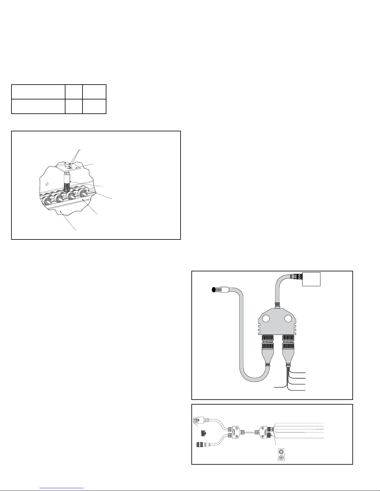
OILER BRUSH ADJUSTMENT
(AJUSTE DEL CEPILLO DEL ENGRASADOR)
OILER BRUSH ADJUSTMENT
It is very important that the oiler brush comes in contact with the chain for proper
lubrication and increased chain life. This can be done by using the adjusting nuts
and support brackets.
• Controlling the ProSort
A good software package is essential for the proper operation of the ProSort sorter .
With proper controls, the sorter will provide accurate, efficient, reliable sorting for
many years. Inadequate controls, however, may result in poor sorter performance
and other mechanical failures of the sorter itself, including “crashes”. Hytrol
recommends using the Hytrol ProLogix software package.
Every sortation system is different, which means that the controls for the system
are custom and unique to that system. These custom controls are provided either
by Hytrol, the Hytrol Integration Partner or a third party.
Hytrol has built into the sorter some of the controls necessary to operate the divert
switches, eliminating the need to control this function externally. Other electrical
control components are provided with the sorter to allow the external controls to
monitor critical items and to provide an interface between the electrical controls
and the mechanical sorter. Still other control components must be provided by the
supplier of the custom controls package to insure proper sorter operation.
This section of the manual includes the following information for the custom
controls provider:
1. A description of the divert switch control components supplied, their function, and
how to interface with them.
2. A description of the other control components provided with the sorter and their
intended function.
3. A description of control components that are not included with the sorter that
must be provided by the controls supplier.
4. Some control do’s and dont’s to assist in the design and installation of the
controls package.
Please read this section thoroughly and share this information with the controls
provider.
DIVERT SWITCH CONTROL
Proper control of the divert switch is critical to the safe and reliable operation of
the sorter. Failure to properly control the divert switch is one of the most common
causes of switch damage and can cause “crashes.”
The divert switch functions similar to a switch on a train track to cause the divert
shoes to travel either in a straight-through, “non-divert” track or diagonally across
the sorter along a “divert track” to push product off of the sorter. When the switch is
SAE ISO
203046 or 68
100
ADJUSTING NUTS
(TUERCAS DE AJUSTE)
OILER SUPPORT BRACKET
(ENGRASADOR DE ESCUADRA
DE SOPORTE)
OILER BRUSH
(CEPILLO DEL ENGRASADOR)
CHAIN
(CADENA)
WEARSTRIP
(TIRA DE DESGASTE)
TAIL SECTION
(SECCIÓN DE RETORNO)
in the “home” position, the divert shoes travel through the switch along the straightthrough track. When the switch is in the “divert” position, the shoes are caused to
move along the divert track.
The transition of the switch between the “home” and “divert” positions must be
accurately timed to prevent sorter crashes. Just as a train track switch cannot
be safely operated while a train is passing through the switch, the divert switch
cannot be safely operated while a divert shoe is passing through the switch. If the
movement of the switch mechanism is not timed to occur only when no shoe is
present in the switch, the guide pin of the shoe may collide with the point of the
divert block, resulting in damage to the switch and potentially costly downtime.
The ProSort has two control components at each divert switch that work together
to accurately time the divert switch movement or operation, eliminating the need
for the controls provider to do so. These components are the smart prox and the
high-speed solenoid air valve.
SMART PROX
The “smart prox” is a special inductive proximity sensor developed exclusively for
Hytrol that has the “intelligence” needed to control the switch timing built-in. The
prox plugs to the y-cable. See Figure 6A.
Brown—+24VDC power input to the prox.
Blue—Ground (-) lead for the prox.
Gray—Divert enable input lead for the prox. When a 24VDC (high) signal is given
to this lead by the system controls, the prox waits for the next time it detects a
divert shoe, at which time it provides a 24VDC output through the y-cable to the
high speed solenoid air valve. The solenoid air valve then causes the switch to
move to “divert” position. All shoes traveling through the switch will then follow the
divert track as long as the enable signal is active (held high). When the divert signal
is removed (taken low) the prox waits for the next time it detects a divert shoe, at
which time it will turn off the output to the solenoid air valve. The switch then returns
to the “home” position, and subsequent shoes will follow the “non-divert” track. The
enable signal to this lead is the only signal that the system controls must
provide to control divert switching.
Y Cable
The y-cable is used to connect the smart prox, solenoid air valve and the system
controls. The male micro cord set from the smart prox connects to the terminal
#1 of the y-cable. The pico pigtail, of the y-cable, connects to the male plug on
the solenoid air valve at divert switch. The micro cord set with female end, plugs
to terminal #2 of the y-cable. The leads from the terminal #2 cord set have the
following functions (Fig. 6A). NOTE: Y-cable not used on dual divert sections.
Black—Standard prox output lead. This lead provides a 24VDC (high) signal each
time the prox detects a divert shoe. This is an optional output and is to be used at
the discretion of the controls provider.
SOLENOID
FIGURE 6A
SMART PROX
SMART
PROX
SERVO MOTOR CONNECTOR
(CONECTOR DE SERVOMOTOR)
END VIEW
(VISTA POSTERIOR)
HOMING PROX
(SENSOR DE PROXIMIDAD
DE AUTODIRECCIÓN)
SMART PROX
AND VALVE
CONNECTION
(SMART PROX Y
CONEXION A
VALVULA SOLO)
1 2
(NOT USED/SIN USAR)
SMART PROX CORD SET
WHITE/BLANCO
(JUEGO DE CABLES
SMART PROX)
SMART PROX
TOP VIEW
BROWN/CAFÉ +24 VOLTS DC/+24 V CC
WHITE/BLANCO PROX OUTPUT/SALIDA DEL SENSOR DE PROXIMIDAD
BLUE/AZUL +24 VOLTS DC/+24 V CC
BLACK/NEGRO DIVERT ENABLE/HABILITAR DESVIACIÓN
GRAY/GRIS ALL SYSTEMS GO SIGNAL/
VALVE
(VALVULA
SOLENOIDE)
SMART PROX
TO SOLENOID
"Y" CONNECTOR
032.21124
(SMART PROX Y
A SOLENOIDE
CABLE Y)
SMART PROX
CORD SET
(JUEGO DE CABLES
SMART PROX)
BROWN/CAFÉ
+24 VOLTS DC/+24 V CC
BLUE/AZUL
DC COMMON/CC COMÚN
GRAY/GRIS
SMART PROX ENABLE/
HABILITAR SMART PROX
BLACK/NEGRO
SMART PROX STATE/
ESTADO DE SMART PROX
SEÑAL DE TODOS LOS SISTEMAS LISTOS
(VISTA SUPERIOR)
FIGURE 6B
6
Page 7

ELECTRICAL REQUIREMENTS
• Customer supplied DC Power: 300mA at 24VDC
• All inputs to Smart Prox are sinking.
• All outputs from Smart Prox are sourcing.
HIGH-SPEED SOLENOID AIR VALVE
The solenoid air valve is used to receive the smart prox output signal and provide
air to the proper end of the divert switch cylinder to move and hold the switch in
either the “home” or “divert” positions. The valve used is specially designed for the
high speed operation necessary for proper divert switch timing.
The two inputs of the solenoid are non-polarized, allowing either lead to be used
as input or ground for the valve. The solenoid requires 24VDC, 6W to operate.
The solenoid air valve is controlled directly by the smart prox. Direct control of this
valve by the controls package is not required or advised.
Other Control Components Supplied with the Conveyor
VARIABLE FREQUENCY DRIVE CONTROLLER
The variable frequency drive (VFD) is a motor controller that has three functions:
1. It provides a smooth acceleration of the drive motor, allowing the sorter to slowly
“ramp up” to full speed. This protects the sorter components from the stress of a
full-speed start up.
2. It allows the speed of the sorter to be adjusted to match speed requirements of
the system. Also, it allows the sorter to be operated at a very slow speed during
installation “Debugging” and when certain mechanical components are checked
after servicing.
3. It allows the sorter to be operated at a slower speed during “off-peak” seasons,
reducing energy consumption, noise, and wear.
Refer to the VFD manufacturer’s installation manual, provided with the sorter, for
wiring and adjustment instructions.
AIR PRESSURE SWITCH
The air pressure switch (Fig. 4E) is used to detect low operating air pressure.
Operation of the sorter at air pressures under 50 PSI can cause erratic switching
and potential switch damage. If air pressure falls below this level, the sorter must
be shut down until the cause of the pressure drop has been found and remedied.
The pressure switch provides a contact-type output which closes at pressures at
or above about 48 PSI and opens below that air pressure. The system controls
provider should use this switch to monitor air pressure at the sorter and should
shut down the sorter if an open (low) output is detected from the pressure switch.
Refer to the pressure switch manufacturer’s installation manual, provided with the
sorter, for wiring instructions.
SAFETY PROXIMITY SWITCHES
There are safety switch devices located at various locations in the sorter to indicate
when a divert shoe is out of place, an obstruction has entered the sorter, or when
some other event has occurred that could cause damage to the sorter or danger to
personnel. These safety switches use normal inductive proximity switches as the
electrical interface to the system controls.
There are two types of safety switches in the sorter:
1. Shoe position safety switches are switch mechanisms inside the sorter that trip
if a divert shoe passes them that is not in its proper track. They are also used to
detect foreign objects that might fall between the slats and enter the interior of the
sorter. They are made to detect problems on both the upper and return portions
of the sorter.
There is one shoe position safety switch located at the infeed end and one at the
discharge end of the sorter. There are additional switches included for every 30 feet
of sorter length after the first 30 feet. For example, a sorter 50 feet long will have a
total of 3 switches, a sorter 80 feet long will have a total of 4 switches and so on.
These additional switches are spaced evenly along the sorter’s length.
2. The transition safety switch is used to detect when the transition assembly on
the discharge end of the sorter is pushed out of position if a stray divert shoe or a
foreign object makes contact with them.
The normal state of the output of the safety proximity switch is”on” (high). If a switch
detects a problem the signal is changed to “off” (low). The system controls must be
configured to go to an “emergency stop” condition and shut down the sorter and
related equipment when a problem is detected. Restart must not be possible until
the problem is corrected and the safety switch that detected the problem is again
“on” (high).
Refer to the proximity switch manufacturer’s installation manual, provided with the
sorter, for wiring instructions.
CATENARY TAKE-UP PHOTO EYE
The catenary take-up photo-eye monitors the amount of chain sag occurring in
the drive’s catenary area. The photo-eye is a retro-reflective, light-operated type,
positioned in the catenary so that if the carrying chains allow the slats to sag below
a certain level, the beam of the eye is blocked.
The system controls must be configured to stop the sorter when the photo-eye
beam is continuously blocked (photo-eye output is “off” or “low”) and provide an
indication to the sorter operator that the chains must be taken up or shortened
before operating the sorter further.
Refer to the photo-eye manufacturer’s installation manual, provided with the sorter,
for wiring instructions.
ENCODER
An encoder is included with the sorter to provide a pulse signal to be used for
product tracking. The encoder provides a square-wave pulse signal of 30 pulses
per revolution of the sorter infeed shaft. This equates to one pulse for every 1.301
inches of sorter travel.
The encoder requires 24VDC power, and provides a 24VDC pulse output.
Refer to the encoder manufacturer’s installation manual provided with the sorter,
for wiring instructions.
CHAIN OILER SOLENOID
The chain oiler is used to provide automatic lubrication of the carrying chains
during sorter operation. When the oiler solenoid valve is energized, oil is allowed
to gravity feed from the oiler reservoir, through metering valves, to brushes located
above the return chains in the sorter.
The system controls should be configured to activate the chain oiler solenoid for a
duration equal to one complete revolution of the carrying chains about every forty
hours of operation. The actual amount of oil applied to the chains is controlled by
the metering screws (see “Conveyor Set-up” section of this manual). The chain
oiler solenoid requires 24VDC power to operate.
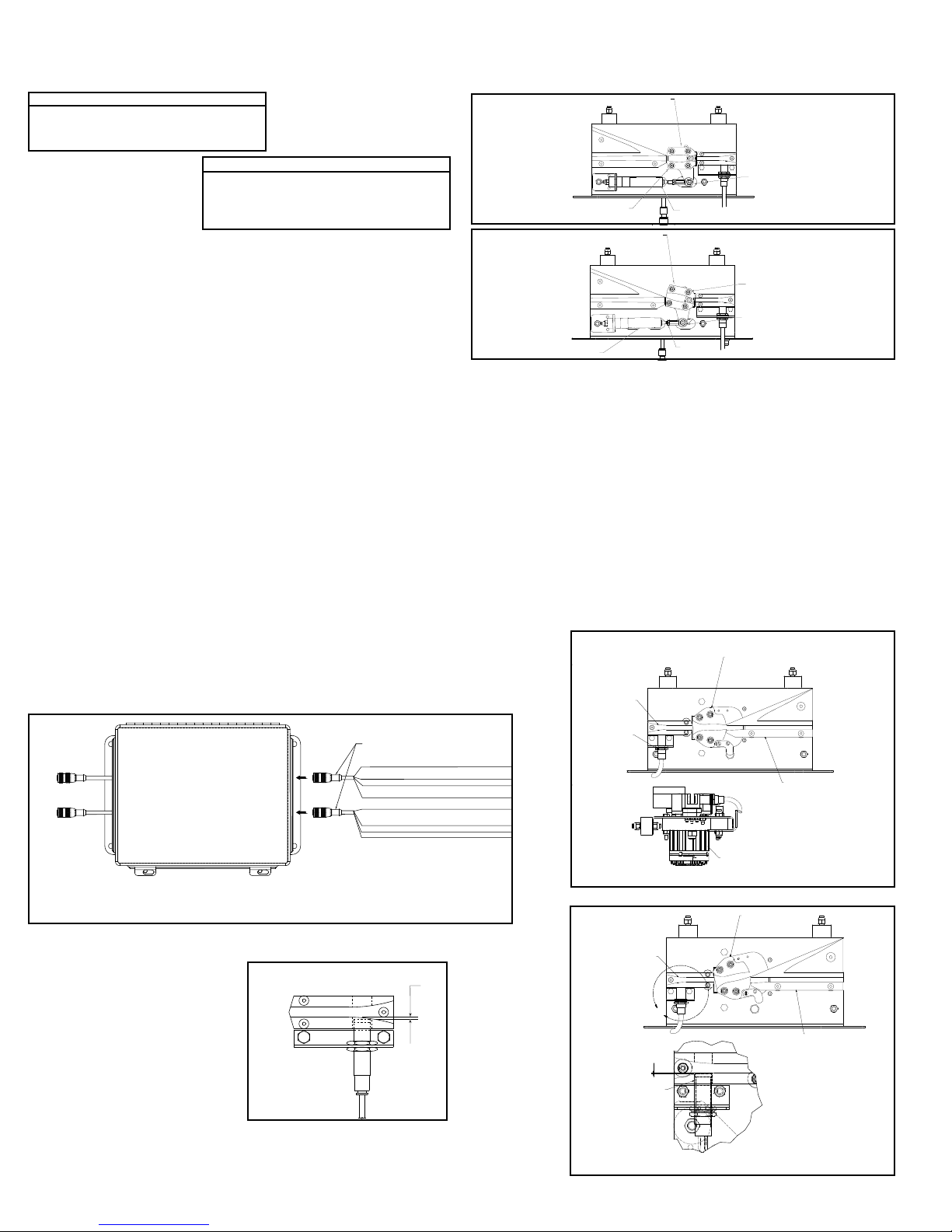
LOST BEARING DETECTION
The missing bearing block is used to detect a bearing missing from a divert shoe.
A divert shoe that does not have a bearing on the bottom can cause damage to
the sorter. The missing bearing block uses two proximity switches located in the
return section of the sorter to detect the presence of a bearing on the shoe. If one
prox detects a bearing being present but the other does not, the block removes its
output to indicate a missing bearing was detected. Missing bearing prox is located
in the bottom of the discharge divert section. The missing bearing detector has a
normally high signal that will output 24 Volts DC as long as no missing bearings/
pins are detected. If a missing bearing/pin is detected then the signal will go low
and the PLC should stop the sorter. Prior to restarting the sorter, the PLC should
pulse 24VDC to the RESET ERROR input on the missing bearing detector. Doing
this will reset the detector so that the output turns back to on.
The missing bearing detector also has the optional feature of testing for the
proper function of the prox sensors used by the detector. The detector has a
second output (BROKEN PROX ERROR) that is normally high (24 VDC) while
the sensors are functioning normally. This output is activated by a SORTER
RUNNING INPUT to the detector. If a signal (24 VDC) is supplied to that input
while the sorter VFD is enabled it will activate the test to detect a malfunctioning
prox sensor. The SORTER RUNNING INPUT must remain energized for the
BROKEN PROX ERROR OUTPUT to be energized as well as to continue testing
the prox sensors. If a malfunctioning prox sensor is detected then the prox
sensors and all connections to the sensors should be inspected and repaired or
replaced. The BROKEN PROX ERROR should be reset in the same manor to that
of the missing bearing error.
The power to operate the missing bearing detector, the prox sensors, and the
signals going back to the PLC are all from a customer supplied 24 VDC source.
The 24VDC, 200 mA power required is to be provided through the M12 connector
labeled ‘INPUT’.
Control Components Not Supplied with the Conveyor
In addition to the control components supplied with the ProSort sorter, there are
several components that must be supplied by the system control provider. Hytrol
recommends the following control components be used to protect the sorter from
damage due to product jams or other problems.
ADJUSTABLE INSTANTANEOUS MOTOR OVERLOADS
Instantaneous overloads provide protection against sorter “hang-ups” by turning
off the drive if a sudden increase in motor current is detected. By adjusting the
overload limit to slightly above the power required to operate the sorter, any
extra load on the motor, such as would be caused by a product jam or switch
malfunction, would cause the sorter to stop, possibly before significant damage is
done to the equipment.
The instantaneous overloads should be installed in the control panel for the sorter
and sized for the proper power requirements.
PHOTO-EYES
Photo-eyes are common components in systems controls. Hytrol recommends that
photo-eyes be installed at the following locations to perform listed functions. These
are, of course, in addition to other photo-eyes needed in the system.
Induction Photo-eye—A photo-eye mounted at the infeed point of the sorter. This
eye is used to perform the following functions:
1. Signal the system controls that a particular package has entered the sorter.
From this point forward, the package must be tracked using the encoder pulses to
determine when it reaches the proper divert location.
2. Measure the length of the package so that the system controls may assign the
proper number of divert shoes to the package for diverting. Note: Shoes are to be
assigned for the entire length of the package plus one extra shoe is to be assigned
to the trailing end of the package.
3. Check for the proper gap between packages for safe sorting. It is important to
check for the proper gap here, even if it has been set prior to this point, to insure
7
Page 8
that the packages are truly spaced properly. Attempting to sort packages with too
(CONTRA TUERCA)
OUPUT (24V=OK, 0V=MISSING BEARING DETECTED)
SALIDA (24 V = CORRECTO, 0 V = COJINETE FALTANTE DETECTADO)
ERROR DE SENSOR DE PROXIMIDAD DAÑADO (24 = CORRECTO, 0 V = ERROR)
ENTRADA DE ERROR DE RESTABLECIMIENTO
ENTRADA DE FUNCIONAMIENTO DEL CLASIFICADOR ESTÁ ACTIVA.)
(SERVOMOTOR)
SCALE 1.50 : 1
(ESCALA 1.50: 1)
little gap between them can cause jams.
Note: The minimum gap necessary for sorting a package is a function of the width
of the package. The charts below should be used in checking for proper gap.
ProSort 121 (22° Diverts)
0” < W ² 6” Minimum gap = 6”
6” < W ² 18” Minimum gap = 9”
18” < W ² 30” Minimum gap = 12”
* W = Maximum Package Width
Note: When sorting to both
sides, the minimum gap from the
above charts must be increased
by 3 in.
0” < W ² 6” Minimum gap = 6”
6” < W ² 12” Minimum gap = 9”
12” < W ² 18” Minimum gap = 12”
18” < W ² 24” Minimum gap = 15”
ProSort 131 (30° Diverts)
Jam/Confirmation Photo-eye—Photo-eyes mounted on each take-away spur of
the sorter, as close to the sorter as possible. These eyes perform two functions:
1. Detect a product jam at the sorter “exit point.” If a package blocks this photo-eye
for a longer time than it would take for the package to travel past the photo-eye
normally, this indicated that the package is jammed. The sorter should be stopped
and the jam cleared before restarting the sorter.
2. Divert confirmation. If a divert signal is given to a particular divert point, and no
package is detected by the associated jam/confirmation photo-eye, an error has
occurred. The sorter should be stopped and the error found and corrected before
restarting the sorter.
Full Line Photo-eye—Photo-eyes mounted on each divert lane from the sorter,
near the infeed end of that lane. These eyes are used to signal the system controls
that a particular divert lane is full. The controls should then send any further
packages assigned to that lane to the recirculation line until the full line photo-eye
on that lane no longer indicates the full condition.
Recommended Controls Procedures
The following are recommendations to assist in the design and installation of
system controls that are interfacing with ProSort sorters.
• Do not place 24VDC control wires in the same wireway with AC power wires,
especially if the AC power exceeds 240 volts. “Noise” produced in the control wires
by the power wires may produce undesirable effects.
• Do not use optional “standard prox output” of the smart prox as a substitute for
an encoder. The five inch spacing between divert shoes does not provide enough
tracking resolution to accurately sort packages.
• Do not use manual override operator of the solenoid air valve to operate a divert
switch while the sorter is running. Doing so bypasses the switch timing controls and
may cause switch damage or a sorter crash.
• Do treat the tripping of any safety switch, motor overload, or low air pressure
signal as an emergency stop. Inspect the safety switch and other parts of the
sorter to be sure everything is in good working order before starting or restarting
the sorter.
FIGURE 8A
TO PROX 1
(HACIA SENSOR DE
PROXIMIDAD 1)
TO PROX 2
(HACIA SENSOR DE
PROXIMIDAD 2)
OUTPUT
(SALIDA)
INPUT
(ENTRADA)
941.423003
BROWN/CAFÉ NOT USED
WHITE/BLANCO BROKEN PROX ERROR (24=OK, 0V=ERROR)/
BLUE/AZUL COMMON/COMÚN
BLACK/
NEGRO
BROWN/CAFÉ POWER (+24VDC)/ENERGÍA (+24 V CC)
WHITE/BLANCO SORTER RUNNING INPUT (SORTER UP TO SPEED)
ENTRADA DE CLASIFICADOR EN FUNCIONAMIENTO
(CLASIFICADOR A VELOCIDAD NORMAL)
BLUE/AZUL COMMON/COMÚN
BLACK/NEGRO RESET ERROR INPUT/
2. Turn air pressure on and verify that each divert switch is in, or moves to, the
home (non-divert) position (Figure 8C).
3. Check to insure that the smart prox is set properly. The face of the prox should
be set just out of the shoe pin guide path in the switch guide (Figure 8B)
SWITCH BLOCK
FIGURE 8C
NON-DIVERT POSITION
(POSICION DESVIADORA)
AIR RETRACTED
(INTERRUPTOR DE
BLOQUEO)
SWITCH BLOCK
(INTERRUPTOR DE
BLOQUEO)
AIR CYLINDER EXTENDER
(EXTREMO DEL EJE)
DIVERT POSITION
(POSICION DESVIADORA)
ROD END
(EXTREMO DEL EJE)
JAM NUT
ROD END
(EXTREMO DEL EJE)
FIGURE 8D
•Electric Divert Switch Checklist
NOTE: All electric divert servo motors are paired with the associated drives at the
factory. Connecting motors to the wrong drive may have an adverse effect on the
divert operation and could result in physical damage to the sorter. Always connect
the drives to the factory paired motors to prevent damage.
1. Before running the sorter, apply power to the electric switch system and verify
that the diverts are fully in either the home or diverted position. Divert function was
tested at the factory to ensure proper operation. If the diverts are in the diverted
position, they can be returned to the home position, Figure 8E by removing the
enable signal to the Smart Prox and then flagging the Smart Prox to trigger a
move operation.
2. Each time diverts are powered on, the diverter will move slowly until it finds the
home position.
3. Ensure that the “All Systems Go” signal is on before running the sorter.
4. Check to ensure that the Smart Prox is set properly. The face of the prox should
be set just out of the shoe pin guide path in the switch guide (Figure 8F).
FIGURE 8E
SWITCH GUIDE
(GUÍA DEL
INTERRUPTOR)
PROX SWITCH
(INTERRUPTOR
DE PROXIMIDAD)
NON-DIVERT POSITION
(POSICIÓN SIN DESVIACIÓN)
DIVERT BLOCK
(BLOQUE DE DESVIACIÓN)
NON-DIVERT POSITION
(POSICIÓN SIN DESVIACIÓN)
SERVO MOTOR
* BROKEN PROX OUTPUT IS ONLY ACTIVE WHEN SORTER RUN INPUT IS ACTIVE.
(LA SALIDA DE SENSOR DE PROXIMIDAD DAÑADO SOLO SE ACTIVA CUANDO LA
• Pneumatic Divert
FIGURE 8B
Switch Checklist
After all ProSort sections are installed
and aligned, each divert switch should be
checked for proper operations as follows:
1. Before air pressure is supplied to the
divert switch solenoid air valve, manually
pivot the switch back and forth between
the non-divert and divert position
checking for a free and smooth pivoting
movement. Determine and remedy the
cause of any switch binding. For proper switch alignment see figures 8C & 8D.
If switch adjustment is necessary, loosen the jam nut on the cylinder rod. Screw
cylinder rod into or out of rod end to adjust the switch and retighten jam nut.
1/32"
FIGURE 8F
SWITCH GUIDE
(GUÍA DEL
INTERRUPTOR)
1/32
PROX SWTICH
(INTERRUPTOR
DE PROXIMIDAD)
U
DETAIL U
SWITCH BLOCK
(BLOQUE DEL
INTERRUPTOR)
(DETALLE U)
DIVERT BLOCK
(BLOQUE DE
DESVIACIÓN)
DIVERT POSITION
(POSICIÓN DE
DESVIACIÓN)
8
Page 9
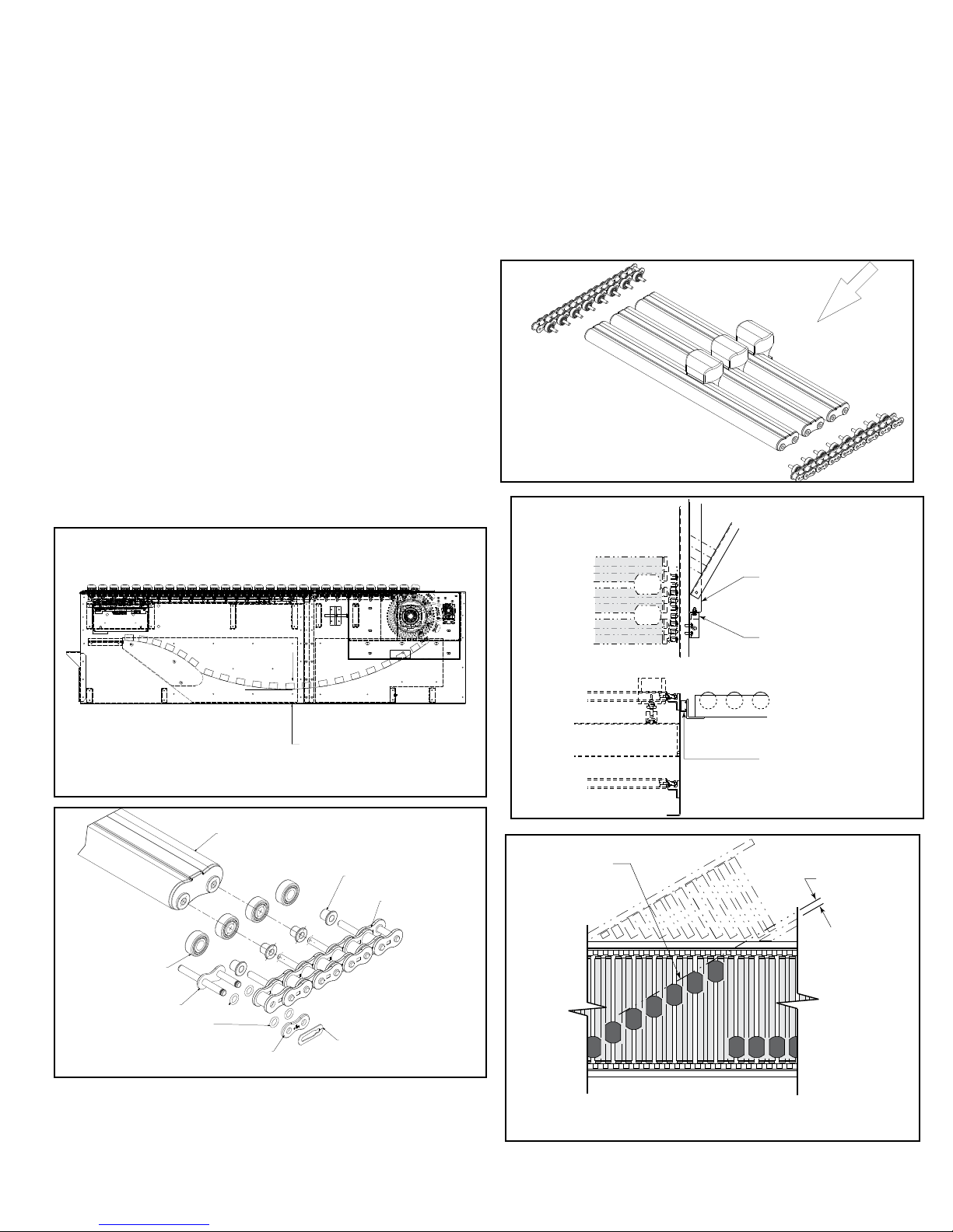
• Carrying Chain Installation
CARRYING CHAIN
The carrying chains are shipped on marked spools, cut to proper length for each
ProSort conveyor. Steps for installing are as follows:
1. Disconnect electrical power to drive motor to prevent accidental start up.
2. Check alignment of chain guides by using two short pieces of chain with slat/
shoe assemblies and bearings assembled to pins. This chain/slat/shoe assembly
should slide freely through chain guides in direction of travel for entire length of
conveyor.
3. Install carrying chains to both sides of conveyor with pins pointed inward
(Figure 9C). Make sure the pins of each chain are directly opposite each other.
Bearings with bushings are installed on each pin. It will be helpful while installing
chains to install one slat/shoe assembly every 4 feet to hold chain in guides.
4. Fasten ends of both chains with connector links as shown in Figure 9B. Follow
manufacturer’s instruction on proper lubrication when installing connector links.
5. Install slat/shoe assemblies onto the extended chain pins on one side of
conveyor – being careful to keep the beveled face of the shoe toward the discharge
end and the side with the rubber insert toward the spur side of conveyor (See
Figure 9B). Lift opposite chain out of chain guide (so chains may be spread apart)
and insert extended chain pins into opposite end of slat/shoe assemblies.
6. After all slat/shoe assemblies are installed, tighten carrying chains with take-up
bolts at drive shaft. Be sure drive and tail shafts are square. Retighten all drive
take-up plate mounting bolts. See Figure 9A for proper slack in chains.
7. Manually crank entire carrying chain assembly through the conveyor to see
that it operates freely and nothing has been dropped into the conveyor during
installation. Also inspect divert shoes to make sure all of them have been installed
on the correct centers. If chains are ever shortened it must be in increments of
three inches.
8. Reconnect electrical power to drive motor.
• Install Guard Rails at Divert Locations
If guard rails are to be installed on the spurs and/or the spur side of the sorter,
care should be taken to insure that the guard rails do not interfere in any way with
the boxes being diverted. Particularly, guards should not be installed in a way that
produces a sharp edge or point in the divert area.
• Locating the Spurs
The take-away spurs must be mounted properly on the divert sections of the
ProSort to insure proper diverting of product. The following installation guidelines
apply to both powered and gravity spurs.
1. Attach spurs to the sorter by bolting the spur attachment bracket to the spur
mounting nuts in the unistrut channel on the sorter side channel (Figure 9D).
Support the spurs as required. Hand-tighten bolts only at this time.
2. Manually place 3 or more shoes along the divert angle as shown. Place a
straight-edge against the shoes to determine the location of the “divert line”. Verify
that the distance between the “divert line” and the “BR” of the spur is at least 1-1/4”
as shown (Figure 9E).
3. Position spur vertically so that the spur rollers/skatewheels are level with the
slats on the sorter. Tighten mounting bolts.
4. Jackbolt Assembly supplied with spur.
FIGURE 9C
W
O
L
F
(FLUJO)
FIGURE 9D
FIGURE 9A
BEARING
(CADENA)
CONNECTOR LINK
(CADENA)
O-RINGS
(CADENA)
COVER PLATE
(CADENA)
SLAT
(CADENA)
ALLOW FROM 5” TO 6” AT INSTALLATION
(PERMITA DE 5 A 6 PULGADAS DE ESPACIO
DURANTE LA INSTALACION)
FIGURE 9B
BUSHING
(CADENA)
(CADENA)
SPRING CLIP
(CADENA)
FIGURE 9E
DIVERT LINE
(LINEA DESVIADORA)
SPUR PLATE
(PLACA DE LA
ESPUELA)
SPUR ATT ACHMENT
BRACKET
(BRAZO SOPORTE
DE LA ESPUELA)
UNISTRUT
(CANAL)
1-1/4" Minimum
(1-1/4" como mínimo)
9
Page 10
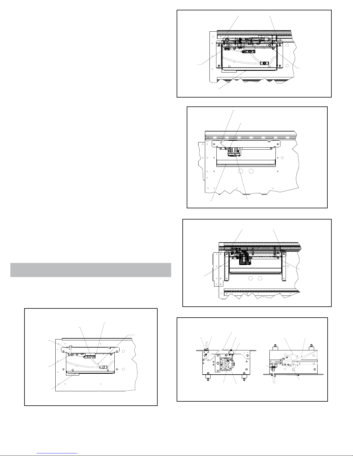
• Pneumatic Divert Switch Removal
(CUBIERTA)
(BLOQUE DE DESVIACIÓN)
Procedure
The ProSort is designed for easy removal of the divert switch assembly for
maintenance or replacement. In order to remove the pneumatic switch assembly
follow the following steps.
1. Unplug the elbow from the fitting on the solenoid air valve by pushing in the red
flange of the fitting and then pulling on the elbow.
2. Disconnect prox switch cord set from y-cable connector (Figure 6A).
3. Remove the cover located on the side of the sorter under the divert switch
assembly by lifting and rotating down and out of the way (Figure 10B).
4. By reaching through the uncovered hole in the side channel remove the two nuts
at the back side of the switch assembly channel. Then remove the two bolts on the
outside of the sorter channel which hold up the front side of the switch assembly
channel (Figure 10B).
5. The front side of the switch assembly channel may then be lowered and the entire
assembly may be removed through the opening in the sorter channel.
6. Check the new switch assembly according to the “Divert Switch Checklist” on
page 8.
7. Install the new divert switch assembly by reversing the procedure by which the old
assembly was removed.
• Electric Divert Switch Removal Procedure
The ProSort is designed for easy removal of the divert switch assembly for
maintenance or replacement. In order to remove the electric switch assembly follow
the following steps.
1. Turn off all power going into the panel connected to the divert that is needing to be
removed. This includes turning the disconnect on the front of the panel to the OFF
position and disconnecting the 3-Phase supply power and control power.
2. Wait at least 90 seconds after removing all power to allow the power to fully
dissipate to a safe level.
3. After waiting 90 seconds, remove the cover located on the side of the sorter under
the divert switch assembly by lifting and rotating down and out of the way. Remove
the 5-wire M12 cable and black power cable from the splitter cable.
4. By reaching through the uncovered hole in the side channel, remove the two nuts
at the back side of the switch assembly channel. Then remove the two bolts on the
outside of the sorter channel which hold up the front side of the switch assembly
channel (Figure 10D).
5. The front side of the switch assembly channel may then be lowered and the entire
assembly may be removed through the opening in the sorter channel.
• Electric Switch Homing Procedure
1.Before starting the sorter, supply 24VDC power to homing prox and Smart prox.
2.Supply 48VDC to the servo motor (Figure 10E).
3.The servo motor goes through a homing procedure where the switch block rotates
to find the home location. This process takes approximately 10 seconds to complete.
4.Wait for the enable signal from the switch.
5.Sorter is now ready to run.
FIGURE 10B
REMOVE
LOCK NUTS
(REMUEVA
LAS TUERCAS)
COVER
(CUBIERTA)
FIGURE 10C
COVER
FIGURE 10D
REMOVE BOLTS
(REMOVER
LOS TORNILLOS)
REMOVE
LOCK NUTS
(REMUEVA
LAS TUERCAS)
PROX SWITCH CORD
(CABLE DEL INTERRUPTOR DE PROXIMIDAD)
SPLITTER CABLE
(CABLE DIVISOR)
SERVO MOTOR
(SERVOMOTOR)
REMOVE BOLTS
(REMOVER
LOS TORNILLOS)
WARNING! Keep ngers clear of switch blcok during the homing procedure.
FIGURE 10A
SOLENOID AIR VALVE
(VÁLVULA DE AIRE SOLENOIDE)
AIR LINE
(TUBERÍA
DE AIRE)
PROX SWITCH
CORD
(CABLE DEL
INTERRUPTOR
DE PROXIMIDAD)
Y-CABLE
(CABLE Y)
COVER
(CUBIERTA)
AIR LINE FITTING
(ACCESORIO DE LA
TUBERÍA DE AIRE)
REMOVE
LOCK NUTS
(REMUEVA
LAS TUERCAS)
FIGURE 10E
CUSTOMER SUPPLIED
24VDC
(24 V CC PROPORCIONADA
POR EL CLIENTE)
SMART PROX
CONNECTION
(CONEXIÓN DE
SMART PROX)
SERVO MOTOR
(SERVOMOTOR)
BOTTOM VIEW
(VISTA INFERIOR )
SERVO I/O SPLITTER CABLE
(CABLE DIVISOR DE E/S SERVO)
TO HOMING PROX
(HACIA SENSOR DE PROXIMIDAD
DE AUTODIRECCIÓN)
I/O TO SERVO MOTOR
(E/S HACIA SERVOMOTOR)
SMART PROX
HYTROL SUPPLIED
48VDC
(48 V CC PROPORCIONADA
POR HYTROL)
SWITCH BLOCK
(BLOQUE DEL
INTERRUPTOR )
REMOVE
LOCK NUTS
(REMUEVA
LAS TUERCAS)
HOMING PROX
(SENSOR DE PROXIMIDAD
DE AUTODIRECCIÓN)
TOP VIEW
(VISTA SUPERIOR)
DIVERT BLOCK
10
Page 11
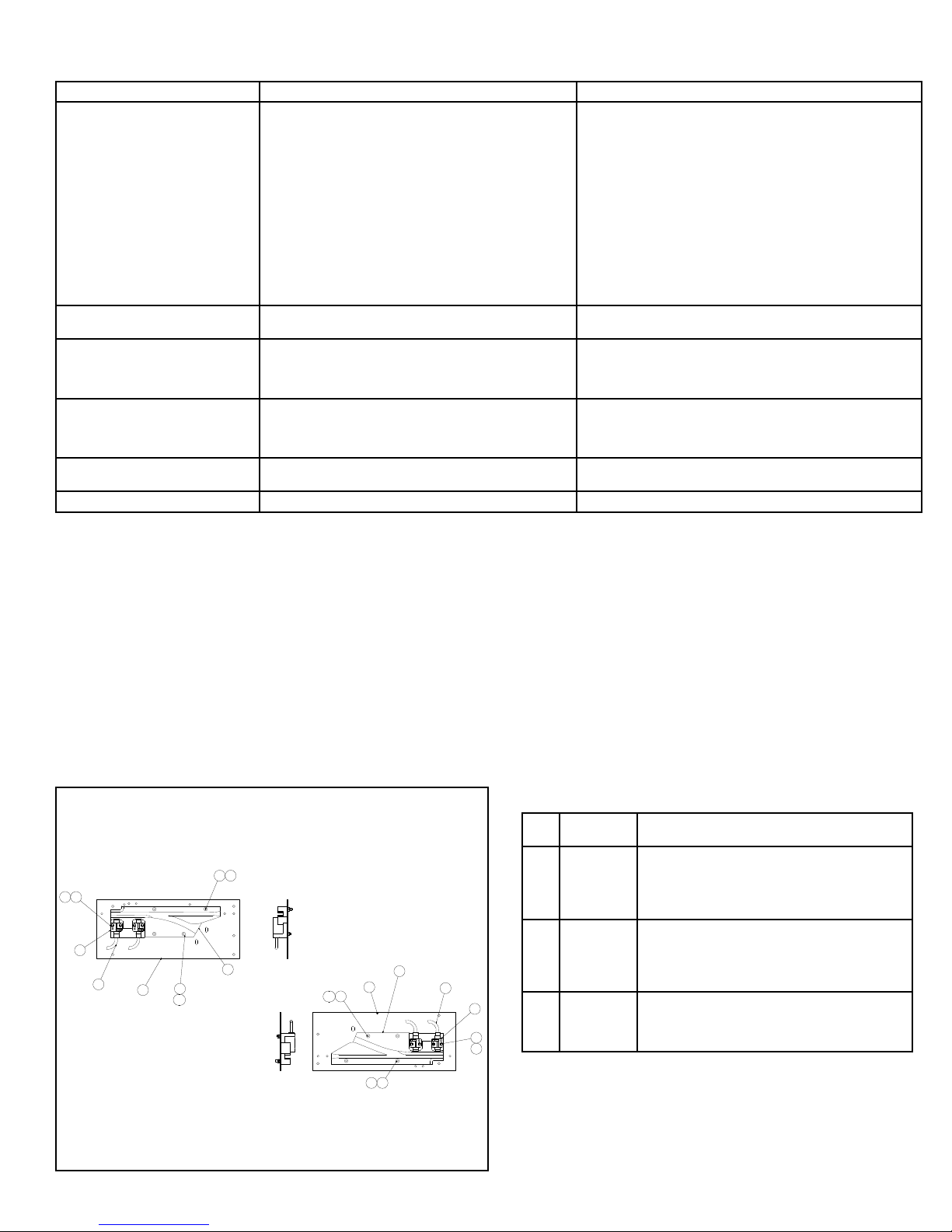
• Trouble Shooting
The following charts list possible problems that may occur in the operation of the ProSort.
TROUBLE SHOOTING DRIVES
TROUBLE CAUSE SOLUTION
Conveyor will not start or shuts off
automatically during operation.
Conveyor takes long time to reach
speed or conveyor jerks when starting.
Divert shoes "jump" during diverting.
Inoperative divert switch.
All divert switches inoperative.
Inoperative electric divert switch
1) Jam eye blocked
2) Tripped internal safety switch.
3) Transition rollers out of position.
4) Proximity switch for internal safety switch or transition rollers
mis-adjusted or defective.
5) Low air pressure.
a) Regular set low.
b) Air line restricted or broken.
c) Air lter clogged.
d) Compressor problem.
e) Lockout closed.
6) Electrical circuits.
7) Variable speed drive mis-adjusted or defective.
8) Drive motor defective.
1) Variable speed drive mis-adjusted or defective. 1) Refer to variable speed drive manufacturer’s manual for trouble
1) Divert shoe tight on slats.
2) Slats dirty.
3) Slats bent.
4) Switch mis-adjusted.
1) No air pressure to cylinder.
2) Lockout closed.
3) Air solenoid valve defective.
4) Proximity switch mis-adjusted or defective.
1) Loss of power to air solenoid valves.
2) Controls failure.
1) No power to electric switch. 1) Check 3-Phase power to the servo drive enclosure.
1) Unblock jam eye.
2) Determine cause of tripping: foreign debris, mislocated divert
shoes, etc., and correct problem.
3) Determine reason for transition rollers being out of position and
correct problem.
4) Adjust or replace proximity switch.
5) Determine reason for low air pressure and correct problem.
6) Check power and wiring.
7) Refer to variable speed drive manufacturer’s manual for trouble
shooting.
8) Replace motor.
shooting.
1) Replace slat/shoe assembly.
2) Clean surface. (Refer to Preventive Maintenance Details)
3) Replace slat/shoe assembly.
4) Refer to Divert Switch Checklist, Page 8 & 9.
1) Check air line and filter regulator. Replace if necessary.
2) Open lockout.
3) Replace.
4) See page 8 & 9 for proper adjust or replace.
1) Correct problem.
2) Trouble shoot control system.
Lost Pin Prox Assembly
30° LOST PIN PROX ASSEMBLY
6 9
7
8
3
2
6
1
10
4
Conjunto de sensor de proximidad de pasador perdido
4
1
610
69
22° LOST PIN PROX ASSEMBLY
Ref.
Part No. Description
No.
1
-
2
941.650185
3
923.0227
4
-
-
092.1793
-
092.1783
-
092.17955
-
092.17855
5
EB-000068
6
2
3
7
8
7
8
9
10
041.800
041.801
042.10234
042.654
042.6545
Y-Block Support Plate - Return (22° or 30°)
Prox Switch - 18MM
Fixing Clamp
Y-Block - LH, 22° Return
Y-Block - RH, 22° Return
Y-Block - LH, 30° Return
Y-Block - RH, 30° Return
Missing Bearing Detection Controller
1/4-20 Hex Locknut - Nylon Insert
#8-32 Hex Locknut - Nylon Insert
#8-32 x 1-3/4 in. lg Round Head Machine Screw
1/4-20 x 2 in. lg Hex Socket Flat Head Cap Screw
1/4-20 x 2-1/2 in. lg Hex Socket Flat Head Cap Screw
11
Page 12
15
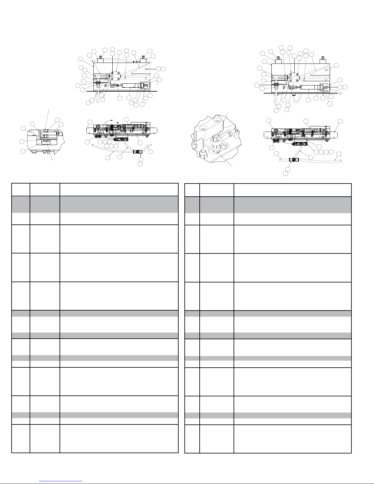
• Pneumatic Divert Switch Assembly Parts Drawing
14
8
LEFT-HAND 30° PNEUMATIC
SWITCH SHOWN SA-061764
TORQUE NUT
TO 225 IN-LB.
6
44
19
5
TORQUE BOLT
TO 110 IN-LB.
Ref.
Part No. Description
No.
1
019.222
2
032.21124
3
032.2113
4
040.100
5
040.20255
6
041.1012
7
041.596
8
041.798
9
041.799
10
041.800
11
041.8005
12
041.802
13
042.59025
14
042.651
15
042.6515
16
042.6535
17
042.654
18
042.6545
19
043.300
20
092.163
21
092.1825
22
MP-002574
23
092.184905
-
092.184906
24
094.107955
25
094.10816
26
094.1149
27
094.11496
28
094.12021
29
094.140
30
094.14015
31
094.1406
32
094.14089
33
094.1465
34
911.0264
35
923.0172
36
923.0173
37
043.101
38
MP-002541
39
-
40
-
41
-
42
-
43
-
44
-
20
21
39
14
12
4
40
34
3
12
15
6
1
41
2
Female Rod End - 5/16-24 RH Threads
Y-Plug Cable Connector
Smart Proximity Switch-24VDC, Customized
1/4-20 X 3/4 in. LG Hex Head Cap Screw, ZP
5/16-24 X 1-1/4 in. LG Hex Bolt, Full TH, GR 8
5/16-24 Hex Nut - Grade 8, Yellow Zinc
5/16-24 NC2B Hex 2-WAY Jam Locknut- REG,
3/8-16 NC2B Hex Locknut- Nylon Insert, ZP
5/16-18 NC2B Hex Locknut-Nylon Insert, ZP
1/4-20 NC2B Hex Locknut-Nylon Insert, ZP
#6-32 Hex Locknut - Nylon Insert, ZP
#10-24 NC2B Hex Locknut- Nylon Insert, ZP
#6-32 X 1-1/4 in. LG Socket Head Mach Screw
#10-24 X 1 in. LG Hex Skt Flat HD Cap Screw
#10-24 X 1-3/4 in. LG Hex Skt Flt HD Cap Screw
1/4-20 X 1-3/4 in. LG Hex Skt Flt HD Cap Screw
1/4-20 X 2 in. LG Hex Skt Flt HD Cap Screw
1/4-20 X 2-1/2 in. LG Hex Skt Flt HD Cap Screw
5/16 in. ID External Lockwasher, ZP
Rubber Vibration Mount - 1-1/2 in. DIA
Switch Guide - ProSort 100
Switch Block - PS100E
Divert Block - LH, 30 DEG, PS100E
Divert Block - RH, 30 DEG, PS100E
4-Way Single Solair Valve - 24VDC
1/8 in. Porous Bronze Mufer
3/8 in. OD Polyurethane Tubing - Black
1/2 in. OD Polyurethan Tubing - Black
Air Cylinder - 9/16 in. Stroke, 20MM Bore
Brass Conn-Straight Male,1/4 in. PLST-1/8 in. NP
Brass Conn-Straight Male, 1/8 in. NPT-3/8 in. PLS
Plastic Elbow - Male, 360D Swivel W/RET
Plastic Tee-1/2 in. PLST-1/2 in. PLST-1/2 in. PLST
Plug-In Reducer - 3/8 in. PLST-1/2 in. Push-In
M18 Internal Tooth Lockwasher, ZP
Positioning Stud - 5/16 in. -18 X 2-1/2 in. LG
Urethane Bushing
5/16 in. ID Flat Steel Washer
Switch Bearing Block - Nylon, ProSort 100
Switch CHNL - PS100E (LH or RH)
PROX SWITCH MOUNTING ANGLE - PS100E
SWITCH MOUNTING ANGLE - PS100E
VALVE MOUNTING ANGLE - INSIDE AIRLINE
CYLINDER MTG ANGLE - BUSHING
SWITCH PLATE WELD -(LH or RH)
12
20
44
A
29
30
25
13
24
11
27
Dibujo de piezas del conjunto de interruptor de desviación neumático
17
22
10
28
7
37
31
26
8
23
36
36
9
39
32
33
20
8
43
TORQUE NUT
TO 48 IN-LB.
27
18
10
37
35
LOCTITE
POSITIONING
STUD TO
CYLINDER WITH
271 LOCTITE
LEFT-HANDED 22° SWITCH ASSEMBLY
SA-067120
TORQUE NUT
TO 225 IN-LB.
TORQUE BOLT TO 110 IN-LB.
TO PLATE.
Ref.
Part No. Description
8
20
39
21
14
4
34
3
40
No.
1
2
3
4
5
6
7
8
9
10
11
12
13
14
15
16
17
18
19
20
21
22
23
24
25
26
27
28
29
30
31
32
33
34
35
36
37
38
39
40
41
42
43
44
019.222
032.21124
032.2113
040.100
040.20255
041.1012
041.596
041.798
041.799
041.800
041.8005
041.802
042.59025
042.651
042.6515
042.6535
042.654
042.6545
043.300
092.163
092.1825
MP-002574
092.184903
092.184904
094.107955
094.10816
094.1149
094.11496
094.12021
094.140
094.14015
094.1406
094.14089
094.1465
911.0264
923.0172
923.0173
043.101
MP-002541
-
-
-
-
-
-
FEMALE ROD END - 5/16-24 RH THREADS
Y-PLUG CABLE CONNECTOR
SMART PROXIMITY SWITCH-24VDC, CUSTOMIZED
1/4-20 X 3/4"LG HEX HEAD CAP SCREW, ZP
5/16-24 X 1-1/4"LG HEX BOLT,FULL TH,GR 8
5/16-24 HEX NUT - GRADE 8, YELLOW ZINC
5/16-24 NC2B HEX 2-WAY JAM LOCKNUT- REG,
3/8-16 NC2B HEX LOCKNUT- NYLON INSERT,ZP
5/16-18 NC2B HEX LOCKNUT-NYLON INSERT,ZP
1/4-20 NC2B HEX LOCKNUT -NYLON INSERT,ZP
#6-32 HEX LOCKNUT - NYLON INSERT, ZP
#10-24 NC2B HEX LOCKNUT- NYLON INSERT,ZP
#6-32 X 1-1/4"LG SOCKET HEAD MACH SCREW
#10-24 X 1"LG HEX SKT FLAT HD CAP SCR
#10-24 X 1-3/4"LG HEX SKT FLT HD CAP SCR
1/4-20 X 1-3/4"LG HEX SKT FLT HD CAP SCR
1/4-20 X 2"LG HEX SKT FLT HD CAP SCR
1/4-20 X 2-1/2"LG HEX SKT FLT HD CAP SCR
5/16"ID EXTERNAL LOCKWASHER, ZP
RUBBER VIBRATION MOUNT - 1-1/2"DIA
SWITCH GUIDE - PROSORT 100
SWITCH BLOCK - PS100E
DIVERT BLOCK - LH, 20 DEG, PS100E
DIVERT BLOCK - RH, 20 DEG, PS100E
4-WAY SINGLE SOL AIR VALVE - 24VDC
1/8” POROUS BRONZE MUFFLER
3/8”OD Polyurethane Tubing - Black
1/2” OD Polyurethan Tubing - Black
AIR CYLINDER - 9/16”STROKE, 20MM BORE
BRASS CONN-STRAIGHT MALE,1/4”PLST-1/8”NP
BRASS CONN-STRAIGHT MALE,1/8”NPT-3/8”PLS
PLASTIC ELBOW - MALE, 360D SWIVEL W/RET
PLASTIC TEE-1/2”PLST-1/2”PLST -1/2”PLST
PLUG-IN REDUCER - 3/8”PLST-1/2”PUSH-IN
M18 INTERNAL TOOTH LOCKWASHER, ZP
POSITIONING STUD - 5/16”-18 X 2-1/2”LG
URETHANE BUSHING
5/16”ID FLAT STEEL WASHER
SWITCH BEARING BLOCK - NYLON,PROSORT 100
SWITCH CHNL - PS100E (LH or RH)
PROX SWITCH MOUNTING ANGLE - PS100E
SWITCH MOUNTING ANGLE - PS100E
VALVE MOUNTING ANGLE - INSIDE AIRLINE
CYLINDER MTG ANGLE
SWITCH PLATE WELD -(LH or RH)
38
12
44
8
20
2
27
33
17
16
14
23
10
22
12
10
43
20
8
35
37
36
1
7
32
28
31
26
9
41
42
29
25
24
30
27
12
Page 13
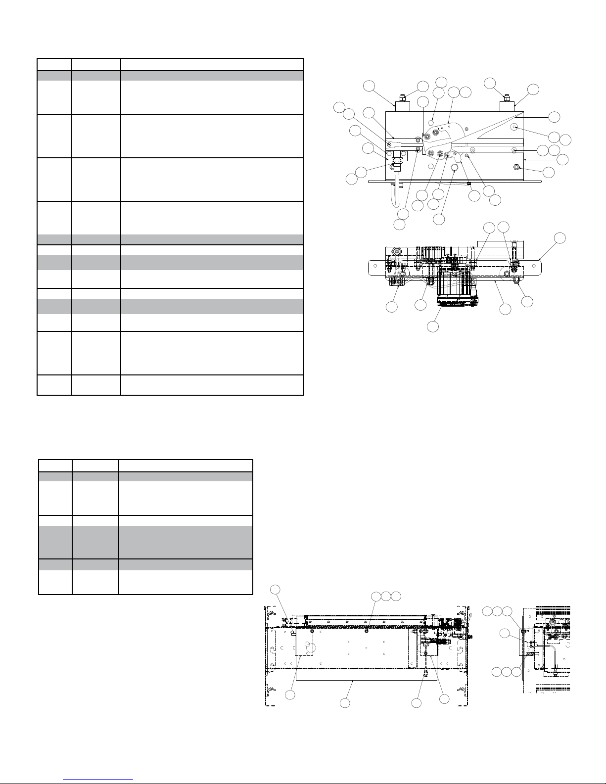
SAFETY SWITCH ASSEMBLY
SA-063997
1
10
7
10
9
2
5 6
1
3
2
4
8
5
6
• Electric Divert Switch Assembly Parts Drawing
Ref. No. Part No. Description
1
2
3
4
5
6
7
8
9
10
11
12
13
14
15
16
17
18
19
20
21
22
23
24
25
26
27
28
29
30
31
32
33
34
35
36
37
032.2113
040.100
040.2031
041.796
041.798
041.799
041.800
041.8005
041.801
041.802
042.10338
042.59025
042.59505
042.6515
042.6535
042.6545
042.6642
046.061
092.163
092.1825
MP-002616
092.18466
092.184907
098.150
923.0220
941.650184
941.721130
941.721132
941.72133
-
-
-
-
-
-
-
-
Smart Proximity Switch-24VDC, Customized
1/4-20 X 3/4 in. LG Hex Head Cap Screw, ZP
5/16-18 X 2 in. LG Hex Head Cap Screw, ZP
1/2-13 NC2B Hex Locknut- Nylon Insert,ZP
3/8-16 NC2B Hex Locknut- Nylon Insert,ZP
5/16-18 NC2B Hex Locknut -Nylon Insert,ZP
1/4-20 NC2B Hex Locknut -Nylon Insert,ZP
#6-32 Hex Locknut - Nylon Insert, ZP
#8-32 Hex Locknut - Nylon Insert, ZP
#10-24 NC2B Hex Locknut - Nylon Insert,ZP
#8-32 X 3/4 in. LG Round Head Machine Screw,ZP
#6-32 X 1-1/4 in. LG Socket Head Mach Screw
1/4-20 X 2-1/4 in. LG Skt HD Cap Screw,STD THD
#10-24 X 1-3/4 in. LG Hex Skt Flt HD Cap Screw
1/4-20 X 1-3/4 in. LG Hex Skt Flt HD Cap Screw
1/4-20 X 2-1/2 in. LG Hex Skt Flt HD Cap Screw
3/8-16 X 3-1/4 in. LG Hex Skt Flt HD Cap Screw
M5-8MM Hex Locknut - Nylon Insert
Rubber Vibration Mount - 1-1/2 in. DIA
Switch Guide - ProSort 100
Switch Bearing -Teknic, Nylon 6/6,PRO 400
Switch Block - Nylatron, ProSort 100E
Divert Block - RH, 30 DEG, PS100E
Spacer - .406 in. ID X .75 in. OD X .375 in. LG
Low Socket Cap Screw - M5-0.8 X 25MM
Inductive Prox - 12MM
Servo - Teknic 3421P, ProSort ELEC Switch
Power Cable - ProSort ELEC Switch Servo
Servo I/O Splitter Cable
Spacer Plate - Teknic Servo, 4GA
CAM - Teknic Servo, 1-5/8 in. DIA
Switch CHNL ELECT- PS100E (LH)
Switch Mounting Angle - PS100E
Prox Switch Mounting Angle - PS100E
Prox Plate
Switch Pivot Weld (LH)
M18 Internal Tooth Lockwasher
Dibujo de piezas del conjunto de interruptor de desviación eléctrico
19
14
20
10
2
34
1
37
7
13
29
6
5
22 36
3
21
11
15
9
7
26
4
27
30° LEFT-HAND ELECTRIC
SWITCH ASSEMBL Y SA-071882-L
5
18
35
25
24
24
19
23
5
17
16
7
32
5
33
19
32
Safety Switch Assembly
Ref. No. Part No. Description
1
2
3
4
5
6
7
-
-
-
8
9
10
032.2116
040.101
040.1035
041.100
041.800
043.100
-
069.715827
069.715833
069.715839
069.715845
090.220
-
-
Prox Switch - DC, Normally Open
1/4-20 x 1" lg. Hex head cap screw
1/4-20 x 1-3/4" lg. Hex head cap screw
1/4-20 Hex Nut
1/4-20 Hex Locknut w/nylon insert
1/4" I.D. Flat steel washer
Sensor Belt
For 27"OAW
For 33"OAW
For 39"OAW
For 45”OAW
Red Vinyl Plastisol Cap
Safety Switch Plate (specify OAW)
Mounting Bracket (LH or RH)
Conjunto de interruptor de seguridad
13
Page 14
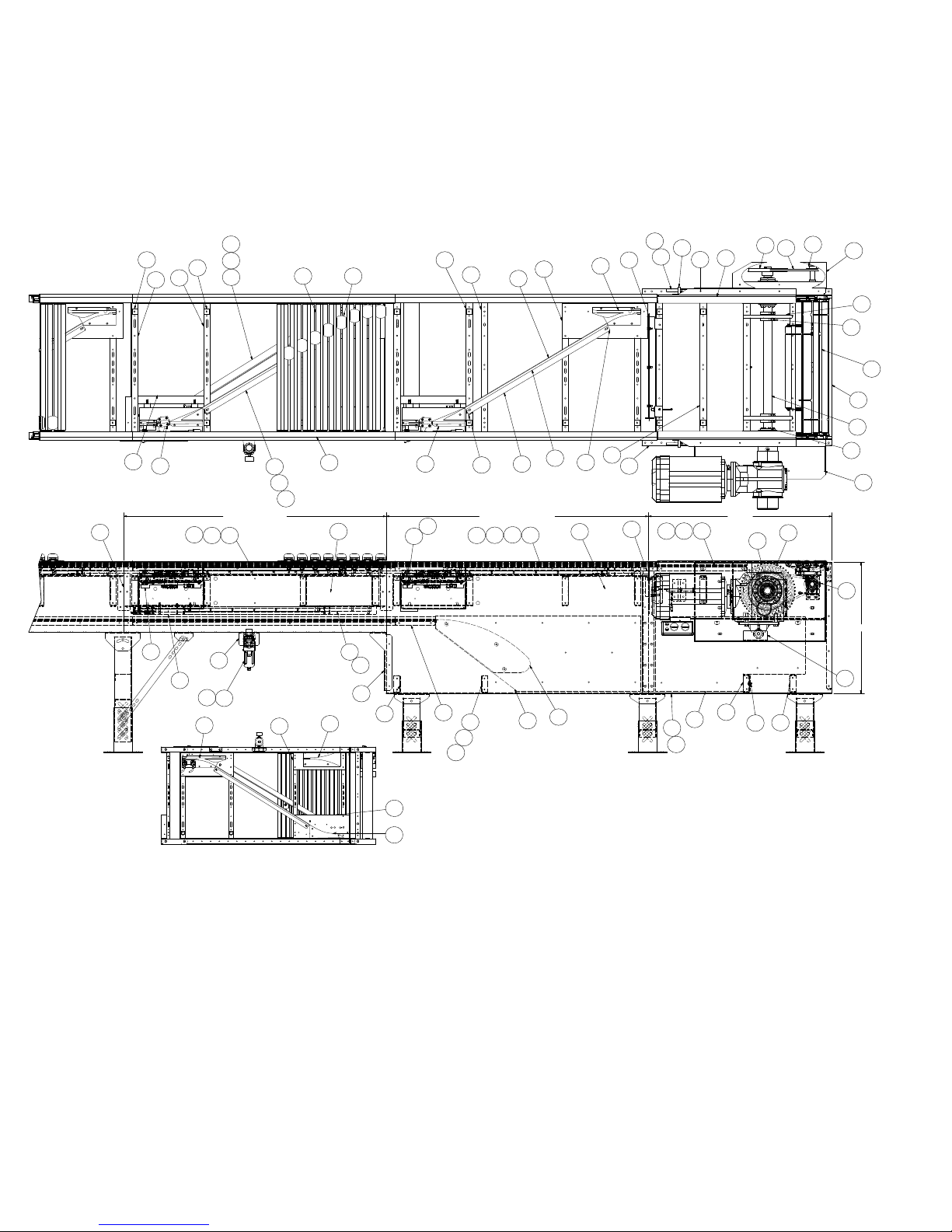
• Model ProSort 131 Elite Parts Drawing
Catenary Divert, Return Divert, and Drive Section
(Sección de transmisión, desviación de retorno y desviación catenaria)
Dibujo de piezas del modelo ProSort 131 Elite
40
11
45
45
46
44
53
36
56
11
124
132
56
39
33
RETURN DIVERT
3338
134
133
127126
33
39
49
35
40
55
50
49
42
50
25
11
24
44
52
36
51
29
30
137
CATENARY DIVERT
124
38
47
37
40
39
34
35
41
31
33
137
43
32
5
28
4
125
24
13
18
12
13
10
17
DRIVE
9
14124
15
1
25
136
22
2
7
21
25
27
8
6
23
16
20
21
26
3
30
19
RETURN DIVERT
BOTTOM VIEW
(SCALE: NONE)
54
48
14
Page 15
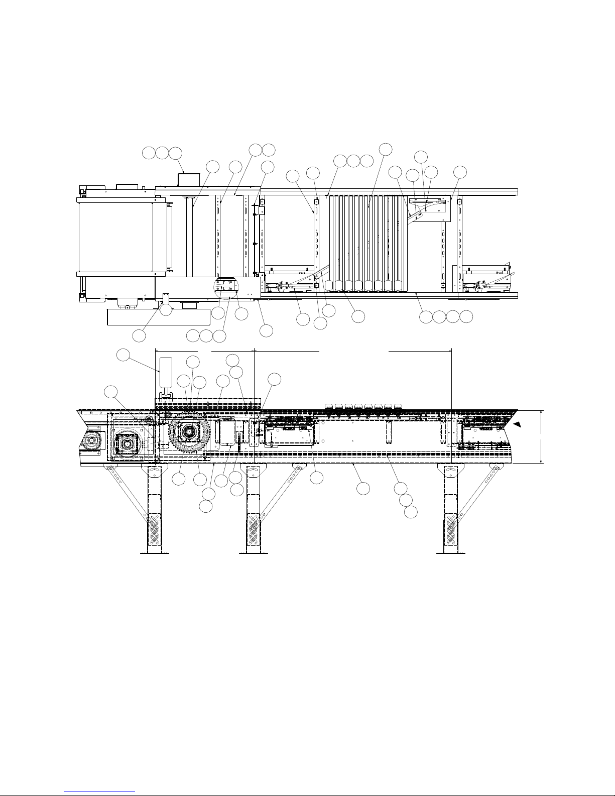
• Model ProSort 131 Elite Parts Drawing
Intermediate Divert and Tail Section
(Sección de retorno y desviación intermedia)
Dibujo de piezas del modelo ProSort 131 Elite
65
58
132131
61
76
63
72
129
67
45
57
7273
63
TAIL
75
8
71
70
6
62
74
125
45
44
77
53
128
11
33
137
INTERMEDIATE DIVERT
126
130
127 343538 124
40
39
137
3731
16
60
21
69
68
64
59
66
52
55
34
38
124
NOTE:
Place chain covers so that no
seams are located within the spur/
diverting area.
NOTA:
Coloque las cubiertas de cadena para
que no haya empalmes en el área de
desvío con la espuela.
15
Page 16
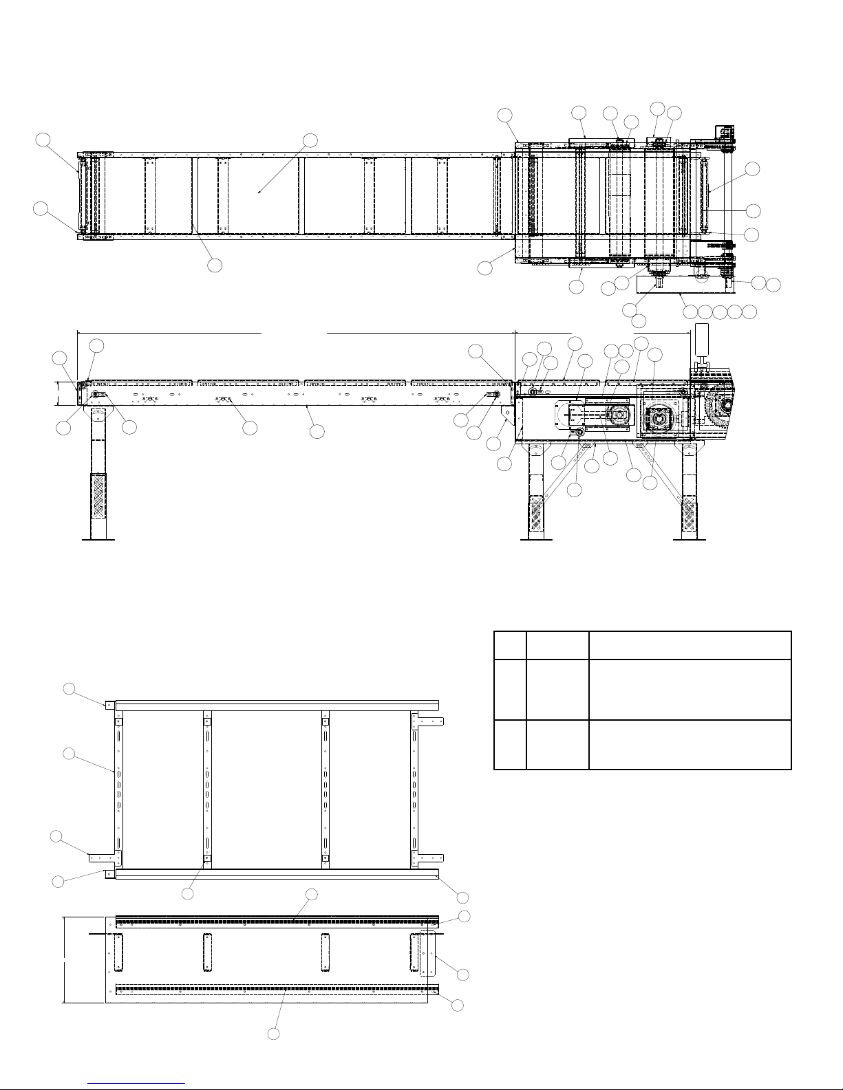
• Model ProSort 131 Elite Parts Drawing
Induction Unit
(Unidad de inducción)
Dibujo de piezas del modelo ProSort 131 Elite
114
105
92
108
112
111
78
79
95
102
101
82
83
81
96
97
80
89
79
103
104
109
110
107
87
95
115
INFEED INDUCTION
121
117
6 1/2
118
116
119
113
122
119
120
117
99
86
93
85
123
98
85
91
107
106
INDUCTION DRIVE
90
84
88
94
100
86
• Model ProSort 131 Elite Parts Drawing
Intermediate Section Assembly
(Conjunto de sección intermedia)
7
9
8
7
16
6
1
Dibujo de piezas del modelo ProSort 131 Elite
Ref.
Part No. Description
No.
1
P-01898
2
P-01899
3
P-01940
4
PT-141785
5
PT-141807
6
PT-142073
7
P-02389
8
PT-145205
9
WA-040365
3
4
5
4
Chain Guide Wearstrip - Top (specify length)
Chain Guide Wearstrip - Bottom (specify length)
Chain Cover (specify length)
Chain Guide Mounting Angle (specify length)
Splice Plate - PS100E
Pin Guide Spacer
Side Angle (specify length & LH or RH)
Joint Pin Guide Plate
Bed Spacer Weldment (specify OAW)
2
16
Page 17
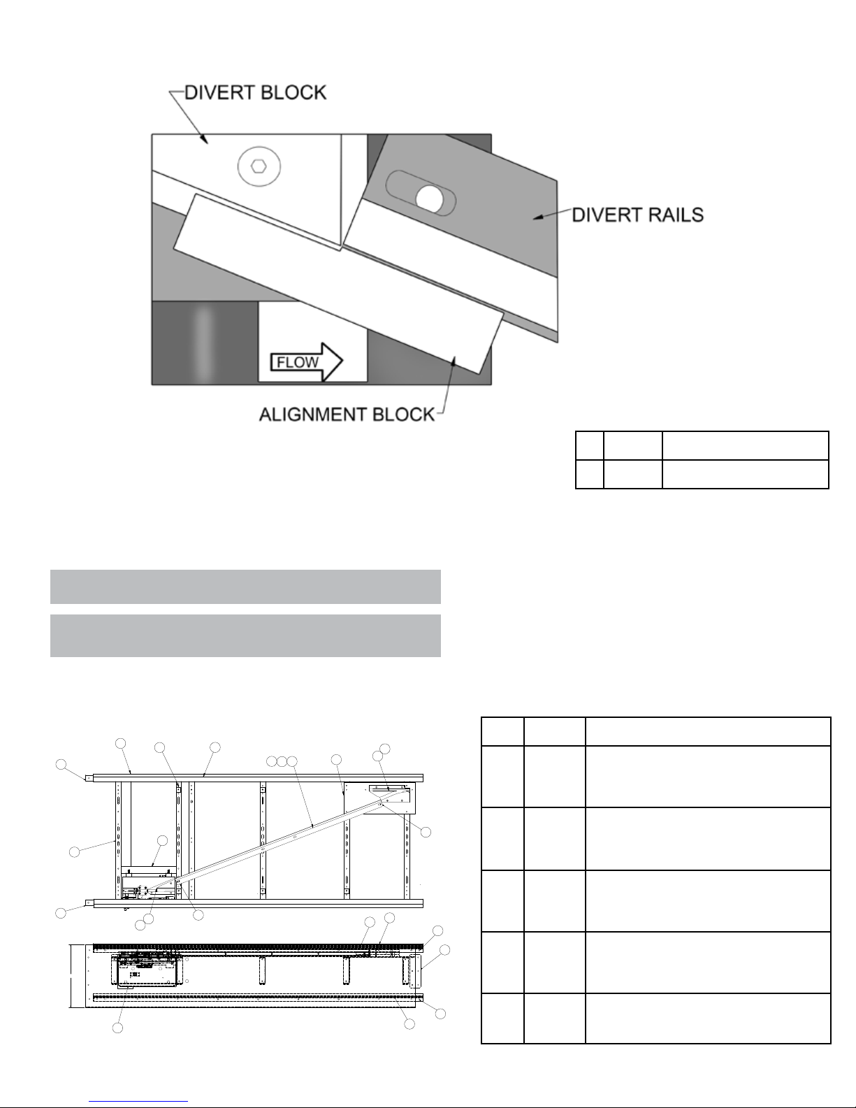
Alignment Offset
(Compensación de alineación)
NOTE:
Use the alignment offset tool to make sure that the divert rail is
properly aligned with the divert block.
NOTA:
Use la herramienta de compensación de alineación para garantizar
que el riel de desviación esté correctamente alineado con el bloque
de desviación.
WARNING! If divert rail and divert block are not properly aligned this can create
¡ADVERTENCIA! Si el riel de desviación y el bloque de desviación no están
correctamente alineados, se puede generar un ruido no deseado y potencialmente
unwanted noise and potentially cause damage.
provocar daños.
30° Divert Section
(Sección de desviación de 30°)
8
11
12
18
12
16
7
19
16
17
6
31315
20
14
2
1
20
4
3
5
Ref.
Part No. Description
No.
1 PT-174779 DIVERT ANGLE ALIGNMENT BLOCK
Ref.
Part No. Description
No.
1
092.1785
2
092.1795
3
MP-002356
4
P-01898
5
P-01899
6
P-01940
7
PT-141782
8
PT-141783
9
-
10
PT-141807
11
PT-142073
12
-
-
-
-
-
-
9
10
9
-
-
-
13
-
14
PT-141784
15
-
16
SA-061764
17
SA-066648
18
WA-040365
19
WA-040366
20
PT-174779
Y-BLOCK - LH, 30 DEG, PROSORT 100E
Y-BLOCK - RH, 30 DEG, PROSORT 100E
UHMW WEARSTRIP - J-LEG (specify length)
CHAIN GUIDE WEARSTRIP - TOP (specify length)
CHAIN GUIDE WEARSTRIP - BOTTOM (specify length)
CHAIN COVER (specify length)
COVER PLATE SWITCH SIDE
COVER PLATE
CHAIN GUIDE MOUNTING ANGLE
SPLICE PLATE - PS100E
PIN GUIDE SPACER
SIDE ANGLE - DIVERT (specify length & LH or RH)
51” long for 27” OAW
60” long for 33” OAW
72” long for 39” OAW
81" long for 45" OAW
DIVERT ANGLE - PS100E
Y-BLOCK SUPPORT PLATE, 30D
WEARSTRIP TIE STRAP
SWITCH ASSY - LH, 30 DEG
SWITCH ASSY - RH, 30 DEG
BED SPACER WELD (specify OAW)
SWITCH SUPT CHNL WELD
DIVERT ANGLE ALIGNMENT BLOCK
17
Page 18
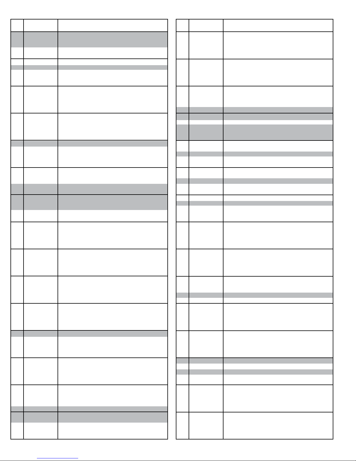
• Model ProSort 131 Elite Parts List
Ref.
Part No. Description
No.
1
010.2052
2
020.150
3
032.2116
4
040.409
5
041.201
6
SA-077155
7
375.03625
8
932.0187
9
MP-002368
10
PT-098832
11
PT-142073
12
PT-144001
13
PT-144126
14
PT-145273
15
PT-145274
16
PT-145302
17
PT-145575
18
PT-145702
19
-
20
PT-152157
21
SA-063930
22
SA-066115
23
SA-068320
24
WA-040985
25
WA-040986
26
WA-041274
27
WA-041284
28
WA-041286
29
033.2130
30
033.2131
31
-
-
092.1785
-
092.1795
32
MP-002572
33
MP-002356
34
-
35
-
36
-
37
-
38
-
39
-
40
-
41
-
42
-
43
-
-
-
-
-
-
-
-
-
44
-
-
SA-061764
-
SA-066648
45
-
46
-
47
-
48
092.18051
49
B-23847
50
MP-002544
51
-
52
-
53
-
54
-
55
-
-
-
-
-
-
-
-
-
56
SA-073869
57
MP-002583
58
095.150
59
095.155
60
927.0360
61
B-18450
62
MP-002345
63
PT-098832-256
Bearing - Cast Iron, 4-bolt, 1-15/16” bore
Sheave - 1A, 8.95”OD X 1-1/2” bore
Proximity Switch
1/2-13 x 6”lg. Hex Bolt, full thread
1/2-13 Hex Jam Nut
Cushion Disk Assembly PS100E
O-ring - Orange, 3/8” diameter
Cushion Disk - 3/4” wide X 11-1/8”OD X 1.945” Bore
Chain Guide Wearstrip - Bottom
Belt Brush (specify OAW)
Pin Guide Spacer
Side Angle- Drive, Inside (LH or RH)
Side Angle- Drive, Outside (LH or RH)
Chain Wearstrip Angle - Drive
Drive Catenary Wearstrip
End Cover - Drive
Brush Holder - 31-1/2”lg. (LH or RH)
Joint Splice Plate - Drive
T orque Arm Bracket
Drive Shaft (specify OAW)
Sprocket Assembly
Transition Drive Assembly (specify OAW)
Transition Roller Assembly (specify OAW)
Bed Spacer Weldment (specify OAW)
Bed Spacer Weldment - Catenary, Lower (specify OAW)
Drive Bearing Mounting Channel Weldment (LH or RH)
Guard Weldment
Take-up Weldment
Photoeye - Retro-Reective, 10-40VDC
Photoeye Mounting Bracket - Ball Swivel
Y-Block
Y-Block - LH, 30°
Y-Block - RH, 30°
Catenary Block
UHMW Wearstrip - J-leg (specify length)
Chain Guide Wearstrip - Top (specify length)
Chain Cover (specify length x 8)
Cover Plate Switch Side
Y-Block Support Plate
Chain Guide Mounting Angle
Divert Angle (specify length)
Wearstrip Tie Strap (specify length)
Catenary Wearstrip
End Plate for Catenary (specify length)
Side Angle - Catenary
51 inch long, for 27”OAW 30° (LH or RH)
60 inch long, for 33”OAW 30° (LH or RH)
72 inch long, for 39”OAW 30° (LH or RH)
81 inch long, for 45”OAW 30° (LH or RH)
Pneumatic Switch Assembly
30 ° Pneumatic Switch Assembly - LH
30° Pneumatic Switch Assembly - RH
Bed Spacer Weldment (specify OAW)
Switch Support Channel Weldment
Photo-eye Channel Weld - Catenary, Lower (specify OAW)
Sweep Block - 30°
Pin Guide Block Plate
Pin Guide
Chain Guide Wearstrip - Bottom
Cover Plate
Splice Plate
Y-Block Support Plate, Return
Side Angle - Return Divert
51 inch long, for 27”OAW 30° (LH or RH)
60 inch long, for 33”OAW 30° (LH or RH)
72 inch long, for 39”OAW 30° (LH or RH)
81 inch long, for 45”OAW 30° (LH or RH)
Lost Pin Prox Assembly (22° or 30° & LH or RH)
Infeed Guide
Chain Lubricator w/2 feeds
Shank Brush for Chain Lubricator
Bearing - 4-Bolt, 1-15/16” bore
Oiler Mount Bracket
Chain Guide Wearstrip - Tail
Belt Brush - 32”lg.
Ref.
Part No. Description
No.
64
PT-126624
65
PT-141806
66
PT-141808
67
PT-141809
68
PT-141810
69
PT-141811
70
PT-141994
71
PT-141996
72
PT-145267
73
PT-145270
74
PT-145325
75
PT-167701
76
SA-073294
77
WA-040390
78
010.203
79
010.2045
80
049.310
81
-
82
-
83
-
84
B-04655
85
B-04842
86
B-15299
87
B-23116
88
B-23159
89
B-23162
90
B-23294
91
B-23296
92
B-23297
93
B-23299
94
B-23302
95
B-23575
96
PT-054185
97
PT-145144
98
PT-145145
99
PT-145147
100
PT-145156
101
PT-145175
102
PT-145227
103
PT-167436
104
PT-167440
105
PT-167463
106
PT-167464
107
PT-167697
108
PT-167711
109
PT-168478
110
-
111
SA-072835
112
SA-072884
113
B-23585
114
B-23578
115
-
-
B-22241
-
B-22242
-
B-22243
-
B-22244
-
B-22224
-
B-22245
116
B-23579
117
B-03191
118
B-03894
119
B-00944
120
B-01982
121
B-03916
122
-
-
B-21500
-
B-21501
-
B-21502
-
B-21170
-
B-21503
-
B-21504
-
B-21505
-
B-21506
-
B-04923
-
B-21507
Lista de piezas del modelo ProSort 131 Elite
Cover Plate (specify OAW)
End Channel - Tail (LH or RH)
Oiler Support Bracket
Tail Shaft (specify OAW)
Tail Channel - LH, 30”lg.
Tail Channel - RH, 30”lg.
Bearing Spacer Plate
Chain Wearstrip Angle - Tail
Brush Holder - 32”lg.
Brush Holder - Right Angle
Infeed Guide Plate
Drive Shaft Slot Cover
Bearing Cover Kit
End Cover Weldment (LH or RH)
Bearing - Cast Iron, 4-bolt, 1-7/16” bore
Bearing - Cast Iron, 4-bolt, 1-11/16” bore
1/4-20 U-type Speed Nut
Timing Belt Sprocket - 1-11/16”Bore
Timing Belt Sprocket - 1-1/2”Bore
Timing Belt
Bearing Guide Spacer - Take-up pulley
11/16” Hex Idler Mounting Bracket
25 Heavy Duty Snub Idler
Top Drive Cover
Cover Weldment
Pulley Plate Weldment
Slider Pan (specify OAW)
6”Dia. Take-up Pulley Weldment (specify OAW)
Take-up Plate Weldment - 6” Take-up Pulley
Butt Coupling Angle (LH or RH)
Take-up Bolt Weldment
2-1/4” Dia. Pulley Assembly (specify induction OAW)
Induction Drive Channel
Drive Side Plate (LH or RH)
Drive End Channel (specify OAW)
Top Drive Cover - Slave Side
Bottom Drive Guard (specify OAW)
Pulley Mounting Bracket
Nip Point Guard (specify induction OAW)
Slave Guard Mounting Bracket
Slave Guard (LH or RH)
Bearing Extend Channel - Induction Drive
Bearing Flange Cover - Induction Drive
Take-up Bearing Cover
Bearing Guide - Take-up Pulley
Slave Cut-out Cover - Induction Drive
Chain Guard Assembly
Bearing Cover Kit
8”Dia. Center Drive Pulley (specify OAW)
Belt Kit (specify BR & section length)
Pulley Mount
Bolt-in Pan (specify BR)
16-1/2” long
19-1/2” long
22-1/2” long
25-1/2” long
28-1/2” long
31-1/2” long
Nip Point Guard (specify BR)
Butt Coupling Angle
2-1/8”OD Roller Assembly (specify BR)
7/16” Hex Idler Bracket
1.9”OD Galvanized Roller Assembly (specify BR)
Bed Spacer (specify BR)
Side Channel
2 ft. Long
2 ft. 3 in. Long
2 ft. 6 in. Long
2 ft. 9 in. Long
3 ft. Long
3 ft. 3 in. Long
3 ft. 6 in. Long
3 ft. 9 in. Long
4 ft. Long
4 ft. 3 in. Long
18
Page 19
• Model ProSort 131 Elite Parts List
Ref.
Part No. Description
No.
-
-
-
-
-
-
-
-
-
-
-
-
-
-
-
-
-
-
-
-
-
-
123
124
125
126
127
128
129
130
131
132
133
134
135
136
137
B-21508
B-21509
B-02636
B-23308
B-23309
B-23310
B-05494
B-23311
B-23312
B-23313
B-21606
B-23314
B-12082
B-23315
B-09908
B-23568
B-23569
B-23570
B-21607
B-23571
B-23572
B-23573
B-02633
B-23581
069.7501
SA-063997
SA-061763
092.1857
029.2658
029.2666
011.1004
PT-089907
094.1912
094.190
B-11302
032.293
032.2185
PT-174779
4 ft. 6 in. Long
4 ft. 9 in. Long
5 ft. Long
5 ft. 3 in. Long
5 ft. 6 in. Long
5 ft. 9 in. Long
6 ft. Long
6 ft. 3 in. Long
6 ft. 6 in. Long
6 ft. 9 in. Long
7 ft. Long
7 ft. 3 in. Long
7 ft. 6 in. Long
7 ft. 9 in. Long
8 ft. Long
8 ft. 3 in. Long
8 ft. 6 in. Long
8 ft. 9 in. Long
9 ft. Long
9 ft. 3 in. Long
9 ft. 6 in. Long
9 ft. 9 in. Long
10 ft. Long
Gussett Angle (LH or RH)
Bearing Prole
Saftey Switch Assembly (specify OAW)
Slat Assembly (specify OAW)
Divert Shoe
#60XLO Riveted O-ring Chain
Connector Link - #60XLO Chain
Bearing - Single row radial
Encoder Cover
Pressure Switch
Filter Regulator
Mounting Angle - Filter/Reg. Kit
Encoder Kit - 30PPR
Reector - 3.30” dia.
Divert Angle Alignment Block
Lista de piezas del modelo ProSort 131 Elite
19
Page 20
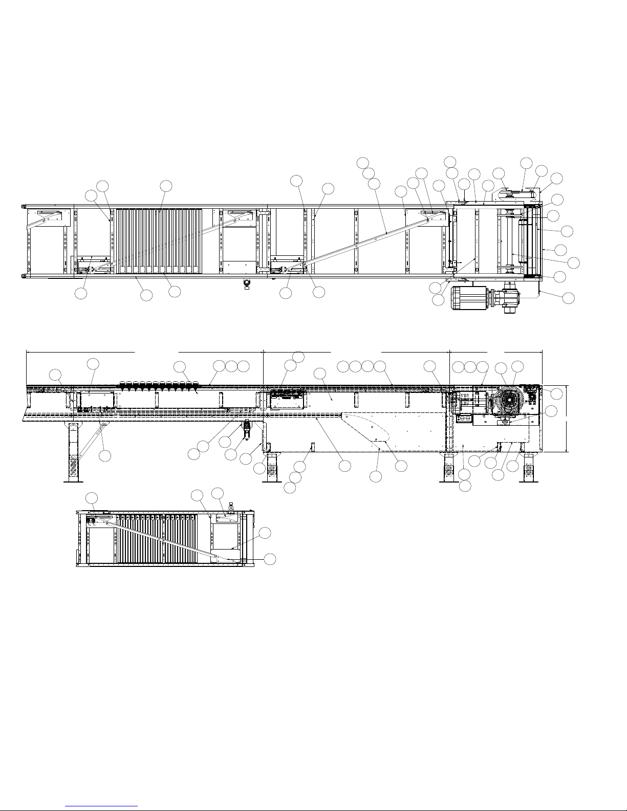
• Model ProSort 121 Elite Parts Drawing
Catenary Divert, Return Divert, and Drive Section
(Sección de transmisión, desviación de retorno y desviación catenaria)
Dibujo de piezas del modelo ProSort 121 Elite
40
124
39
33
34
35
38
51
41
137
37
32
11
45
46
36
53
56
56
126
127
35
RETURN DIVERT
33
124
55
49
49
38
134
50
133
42
25
50
11
44
36
29
30
24
137
52
47
CATENARY DIVERT
43
5
31
4
17
28
125
24
13
18
10
DRIVE
9
14124
25
136
12
13
7
2
1
15
22
27
8
6
23
16
20
21
26
21
3
19
30
25
RETURN DIVERT
BOTTOM VIEW
(SCALE: NONE)
54
48
20
Page 21
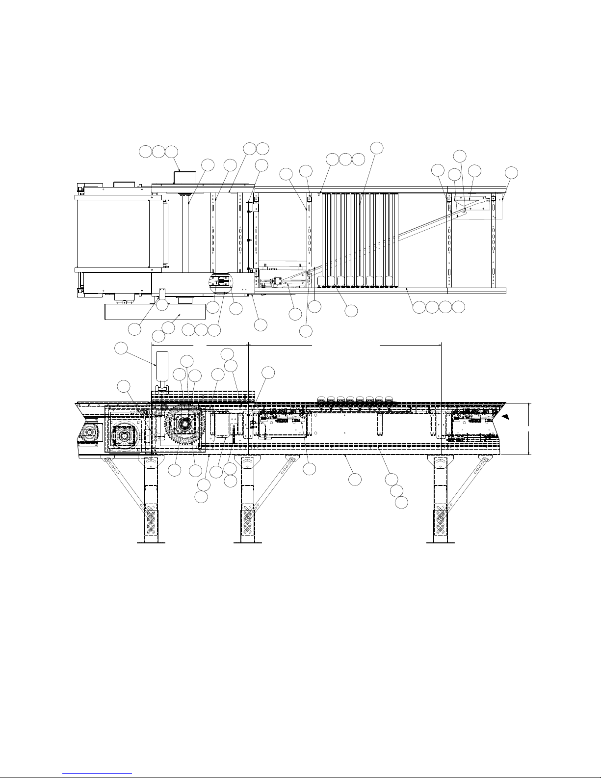
• Model ProSort 121 Elite Parts Drawing
Intermediate Divert and Tail Section
(Sección de retorno y desviación intermedia)
Dibujo de piezas del modelo ProSort 121 Elite
58
65
61
135
131
83
82
76
127
130
126
137
40
39
343538 124
31
37
16
63
72
129
67
45
57
7273
63
TAIL
75
8
71
62
70
6
74
125
45
44
77
53
128
11
33
137
INTERMEDIATE DIVERT
60
21
69
68
64
59
66
52
55
34
38
124
NOTE:
Place chain covers so that no
seams are located within the spur/
diverting area.
NOTA:
Coloque las cubiertas de cadena para
que no haya empalmes en el área de
desvío con la espuela.
21
Page 22
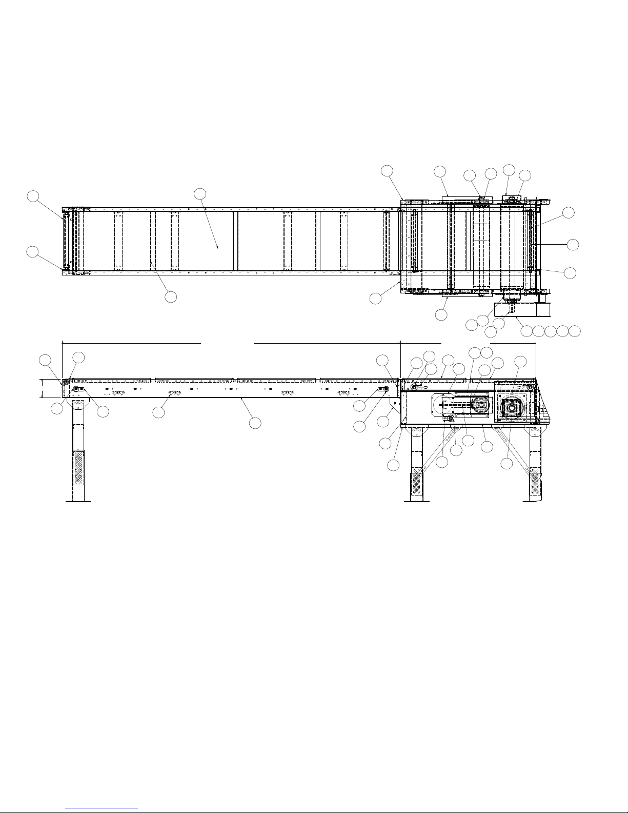
• Model ProSort 121 Elite Parts Drawing
Induction Unit
(Unidad de inducción)
Dibujo de piezas del modelo ProSort 121 Elite
95
114
117
6 1/2
118
116
119
121
115
113
INFEED INDUCTION
122
119
120
105
108
92
97
112
111
78
79
95
102
101
81
80
89
96
79
103
104
109
110
87
99
117
123
98
100
86
93
107
107
INDUCTION DRIVE
90
85
86
85
91
106
84
88
94
22
Page 23
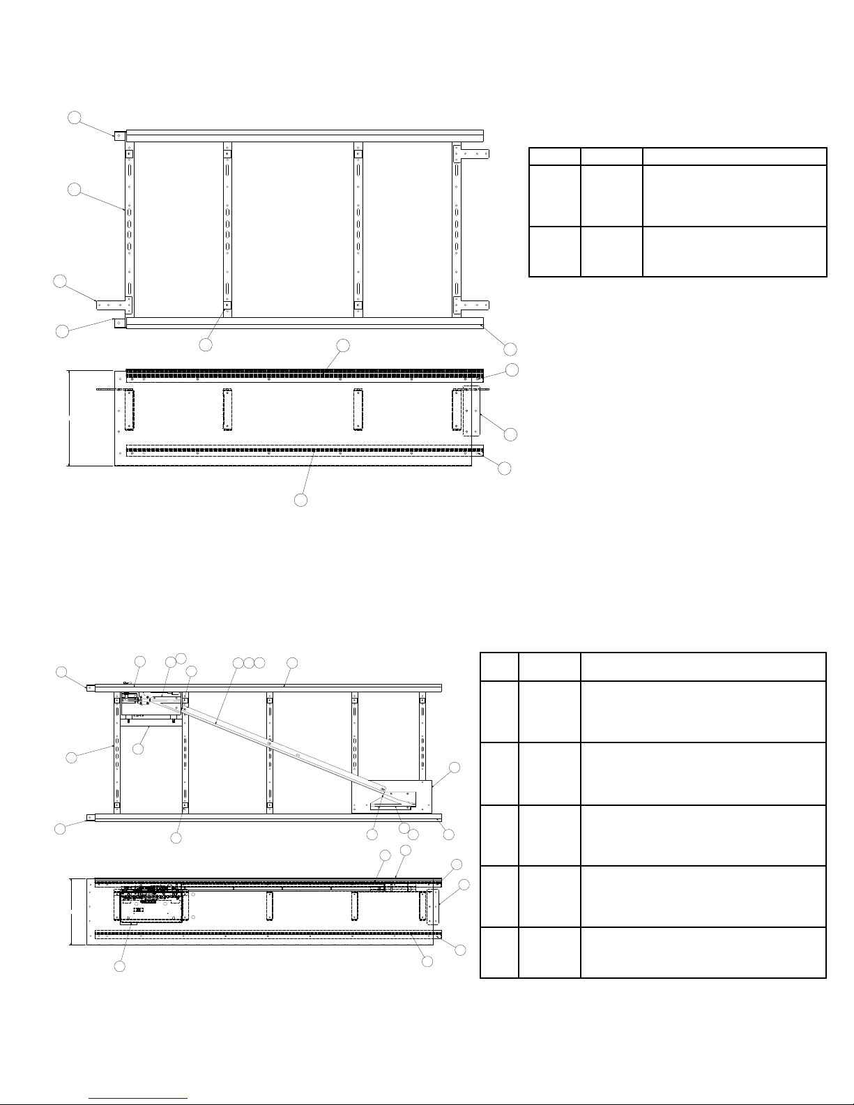
• Model ProSort 121 Elite Parts Drawing
Intermediate Section Assembly
(Conjunto de sección intermedia)
7
9
8
Dibujo de piezas del modelo ProSort 121 Elite
Ref. No. Part No. Description
1
2
3
4
5
6
7
8
9
P-01898
P-01899
P-01940
PT-141785
PT-141807
PT-142073
P-02389
PT-145205
WA-040365
Chain Guide Wearstrip - Top
Chain Guide Wearstrip - Bottom
Chain Cover
Chain Guide Mounting Angle
Splice Plate - PS100E
Pin Guide Spacer
Side Angle (Specify length & LH or RH)
Joint Pin Guide Plate
Bed Spacer Weldment
7
16
6
22° Divert Section
(Sección de desviación de 22°)
17
8
16
12
18
12
16
19
7
20
11
1
2
15
13
3
6
14
1
2
20
4
3
6
9
10
9
5
3
4
5
4
Ref.
Part No. Description
No.
1
092.1782
2
092.1792
3
MP-002356
4
P-01898
5
P-01899
6
P-01940
7
PT-141782
8
PT-141783
9
-
10
PT-141807
11
PT-142073
12
-
-
-
-
-
-
-
-
-
13
-
14
PT-171015
15
-
16
SA-067120
17
SA-067121
18
WA-040365
19
WA-040366
20
PT-174779
Y-BLOCK - LH, 22 DEG, PROSORT 100E
Y-BLOCK - RH, 22 DEG, PROSORT 100E
UHMW WEARSTRIP - J-LEG (specify length)
CHAIN GUIDE WEARSTRIP - TOP (specify length)
CHAIN GUIDE WEARSTRIP - BOTTOM (specify length)
CHAIN COVER (specify length)
COVER PLATE SWITCH SIDE
COVER PLATE
CHAIN GUIDE MOUNTING ANGLE
SPLICE PLATE - PS100E
PIN GUIDE SPACER
SIDE ANGLE - DIVERT (specify length & LH or RH)
69” long for 27” OAW
84” long for 33” OAW
99” long for 39” OAW
114" long for 45" OAW
DIVERT ANGLE - PS100E
Y-BLOCK SUPPORT PLATE, 22D
WEARSTRIP TIE STRAP
SWITCH ASSY - LH, 22 DEG
SWITCH ASSY - RH, 22 DEG
BED SPACER WELD (specify OAW)
SWITCH SUPT CHNL WELD
DIVERT ANGLE ALIGNMENT BLOCK
23
Page 24
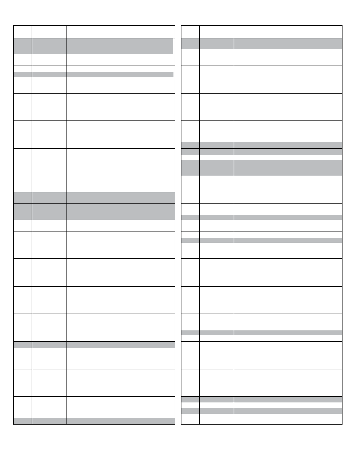
• Model ProSort 121 Elite Parts List
Lista de piezas del modelo ProSort 121 Elite
Ref.
No.
1
2
3
4
5
6
7
8
9
10
11
12
13
14
15
16
17
18
19
20
21
22
23
24
25
26
27
28
29
30
31
-
32
33
34
35
36
37
38
39
40
41
42
43
-
-
-
44
-
45
46
47
48
49
50
51
52
53
54
55
-
-
-
56
57
58
Part No. Description
010.2052
020.150
032.2116
040.409
041.201
SA-077155
375.03625
932.0187
MP-002368
PT-098832
PT-142073
PT-144001
PT-144126
PT-145273
PT-145274
PT-145302
PT-145575
PT-145702
PT-152157
SA-063930
SA-066115
SA-068320
WA-040985
WA-040986
WA-041274
WA-041284
WA-041286
033.2130
033.2131
-
092.1782
092.1792
MP-002572
MP-002356
-
-
-
-
-
-
-
-
-
-
-
-
-
-
SA-067120
SA-067121
-
-
MP-002593
B-23847
MP-002544
-
-
-
-
-
-
-
-
SA-073869
MP-002583
095.150
Bearing - Cast Iron, 4-bolt, 1-15/16” bore
Sheave - 1A, 8.95”OD X 1-1/2” bore
Proximity Switch
1/2-13 x 6”lg. Hex Bolt, full thread
1/2-13 Hex Jam Nut
Cushion Disk Assembly PS100E
O-ring - Orange, 3/8” diameter
Cushion Disk - 3/4” wide X 11-1/8”OD X 1.945” Bore
Chain Guide Wearstrip - Bottom
Belt Brush (specify OAW)
Pin Guide Spacer
Side Angle- Drive, Inside (LH or RH)
Side Angle- Drive, Outside (LH or RH)
Chain Wearstrip Angle - Drive
Drive Catenary Wearstrip
End Cover - Drive
Brush Holder - 31-1/2”lg. (LH or RH)
Joint Splice Plate - Drive
T orque Arm Bracket
Drive Shaft (specify OAW)
Sprocket Assembly
Transition Drive Assembly (specify OAW)
Transition Roller Assembly (specify OAW)
Bed Spacer Weldment (specify OAW)
Bed Spacer Weldment - Catenary, Lower (specify OAW)
Drive Bearing Mounting Channel Weldment (LH or RH)
Guard Weldment
Take-up Weldment
Photoeye - Retro-Reective, 10-40VDC
Photoeye Mounting Bracket - Ball Swivel
Y-Block
Y-Block - LH, 22°
Y-Block - RH, 22°
Catenary Block
UHMW Wearstrip - J-leg (specify length)
Chain Guide Wearstrip - Top (specify length)
Chain Cover (specify length x 8)
Cover Plate Switch Side
Y-Block Support Plate
Chain Guide Mounting Angle
Divert Angle
Wearstrip Tie Strap
Catenary Wearstrip
End Plate for Catenary (specify OAW)
Side Angle - Catenary
69 inch long, for 27”OAW 22° (LH or RH)
84 inch long, for 33”OAW 22° (LH or RH)
99 inch long, for 39”OAW 22° (LH or RH)
114 inch long, for 45”OAW 22° (LH or RH)
Pneumatic Switch Assembly
22 ° Pneumatic Switch Assembly - LH
22° Pneumatic Switch Assembly - RH
Bed Spacer Weldment
Switch Support Channel Weldment
Photo-eye Channel Weldment - Catenary, Lower
Sweep Block - 22°
Pin Guide Block Plate
Pin Guide
Chain Guide Wearstrip - Bottom
Cover Plate
Splice Plate
Y-Block Support Plate, Return
Side Angle - Return Divert
69 inch long, for 27”OAW 22° (LH or RH)
84 inch long, for 33”OAW 22° (LH or RH)
99 inch long, for 39”OAW 22° (LH or RH)
114 inch long, for 45”OAW 22° (LH or RH)
Lost Pin Prox Assembly (22° or 30° & LH or RH)
Infeed Guide
Chain Lubricator w/2 feeds
Ref.
No.
59
60
61
62
63
64
65
66
67
68
69
70
71
72
73
74
75
76
77
78
79
80
81
82
83
84
85
86
87
88
89
90
91
92
93
94
95
96
97
98
99
100
101
102
103
104
105
106
107
108
109
110
111
112
113
114
115
-
-
-
-
-
116
117
118
119
120
121
122
Part No. Description
095.155
927.0360
B-18450
MP-002345
PT-098832-256
PT-126624
PT-141806
PT-141808
PT-141809
PT-141810
PT-141811
PT-141994
PT-141996
PT-145267
PT-145270
PT-145325
PT-167701
SA-073294
WA-040390
010.203
010.2045
049.310
-
-
B-04655
B-04842
B-15299
B-23116
B-23159
B-23162
B-23294
B-23296
B-23297
B-23299
B-23302
B-23575
PT-054185
PT-145144
PT-145145
PT-145147
PT-145156
PT-145175
PT-145227
PT-167436
PT-167440
PT-167463
PT-167464
PT-167697
PT-167711
PT-168478
SA-072835
SA-072884
B-23585
B-23578
B-22241
B-22242
B-22243
B-22244
B-22224
B-22245
B-23579
B-03191
B-03894
B-00944
B-01982
B-03916
-
Shank Brush for Chain Lubricator
Bearing - 4-Bolt, 1-15/16” bore
Oiler Mount Bracket
Chain Guide Wearstrip - Tail
Belt Brush - 32”lg.
Cover Plate (specify OAW)
End Channel - Tail (LH or RH & specify OAW)
Oiler Support Bracket
Tail Shaft (specify OAW)
Tail Channel - LH, 30”lg.
Tail Channel - RH, 30”lg.
Bearing Spacer Plate
Chain Wearstrip Angle - Tail
Brush Holder - 32”lg.
Brush Holder - Right Angle
Infeed Guide Plate
Drive Shaft Slot Cover
Bearing Cover Kit
End Cover Weldment (LH or RH)
Bearing - Cast Iron, 4-bolt, 1-7/16” bore
Bearing - Cast Iron, 4-bolt, 1-11/16” bore
1/4-20 U-type Speed Nut
Timing Belt Sprocket - 1-11/16”Bore
Timing Belt Sprocket - 1-1/2”Bore
Timing Belt
Bearing Guide Spacer - Take-up pulley
11/16” Hex Idler Mounting Bracket
25 Heavy Duty Snub Idler
Top Drive Cover
Cover Weldment
Pulley Plate Weldment
Slider Pan - 22-1/2”lg (specify OAW)
6”Dia. Take-up Pulley Weldment (specify OAW)
Take-up Plate Weldment - 6” Take-up Pulley
Butt Coupling Angle (LH or RH)
Take-up Bolt Weldment
2-1/4” Dia. Pulley Assembly (specify induction OAW)
Induction Drive Channel
Drive Side Plate (LH or RH)
Drive End Channel (specify OAW)
Top Drive Cover - Slave Side
Bottom Drive Guard (specify OAW)
Pulley Mounting Bracket
Nip Point Guard (specify induction OAW)
Slave Guard Mounting Bracket
Slave Guard (LH or RH)
Bearing Extend Channel - Induction Drive
Bearing Flange Cover - Induction Drive
Take-up Bearing Cover
Bearing Guide - Take-up Pulley
Slave Cut-out Cover - Induction Drive
Chain Guard Assembly
Bearing Cover Kit
8”Dia. Center Drive Pulley (specify OAW)
Belt Kit (specify BR & section length)
Pulley Mount
Bolt-in Pan
16-1/2” long
19-1/2” long
22-1/2” long
25-1/2” long
28-1/2” long
31-1/2” long
Nip Point Guard (specify BR)
Butt Coupling Angle
2-1/8”OD Roller Assembly (specify BR)
7/16” Hex Idler Bracket
1.9”OD Galvanized Roller Assembly (specify BR)
Bed Spacer (specify BR)
Side Channel
24
Page 25
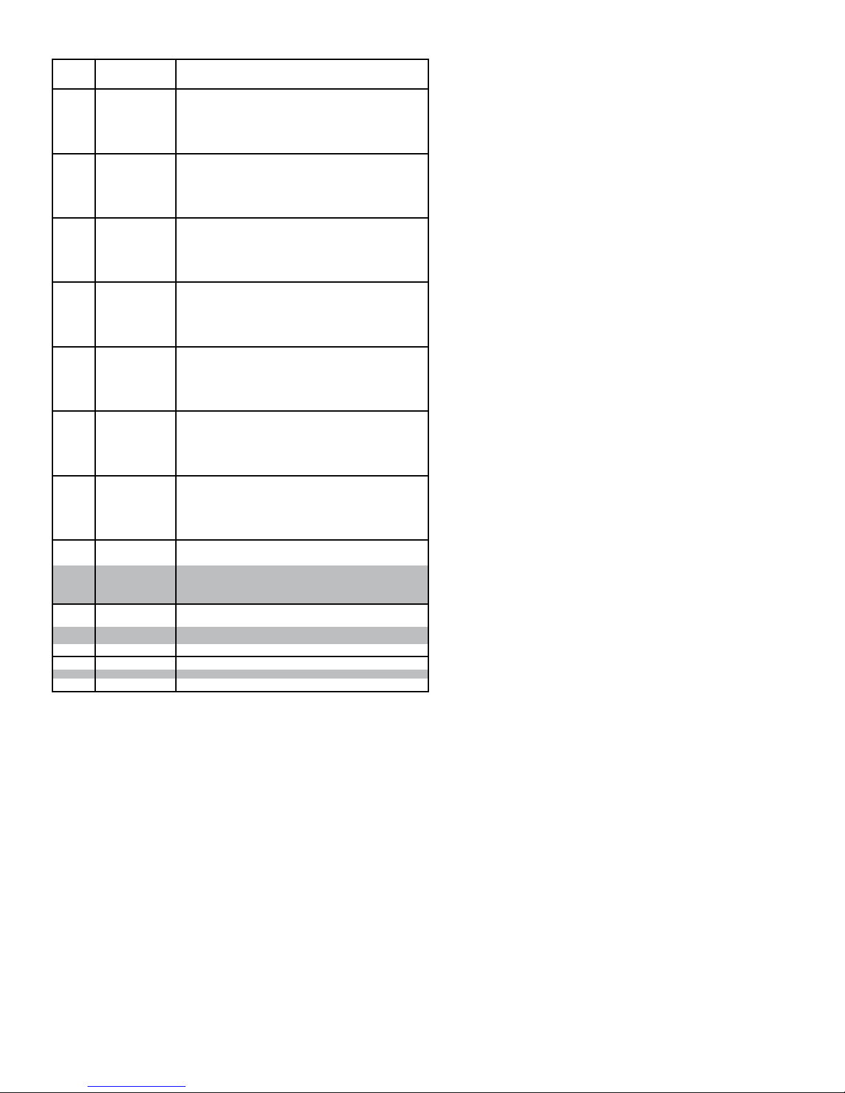
• Model ProSort 121 Elite Parts List
Lista de piezas del modelo ProSort 121 Elite
Ref.
No.
-
-
-
-
-
-
-
-
-
-
-
-
-
-
-
-
-
-
-
-
-
-
-
-
-
-
-
-
-
-
-
-
123
124
125
126
127
128
129
130
131
132
133
134
135
136
137
Part No. Description
B-21500
B-21501
B-21502
B-21170
B-21503
B-21504
B-21505
B-21506
B-04923
B-21507
B-21508
B-21509
B-02636
B-23308
B-23309
B-23310
B-05494
B-23311
B-23312
B-23313
B-21606
B-23314
B-12082
B-23315
B-09908
B-23568
B-23569
B-23570
B-21607
B-23571
B-23572
B-23573
B-02633
B-23581
069.7501
SA-063997
SA-061763
092.1857
029.2658
029.2666
011.1004
PT-089907
094.1912
094.190
B-11302
032.293
032.2185
PT-174779
2 ft. Long
2 ft. 3 in. Long
2 ft. 6 in. Long
2 ft. 9 in. Long
3 ft. Long
3 ft. 3 in. Long
3 ft. 6 in. Long
3 ft. 9 in. Long
4 ft. Long
4 ft. 3 in. Long
4 ft. 6 in. Long
4 ft. 9 in. Long
5 ft. Long
5 ft. 3 in. Long
5 ft. 6 in. Long
5 ft. 9 in. Long
6 ft. Long
6 ft. 3 in. Long
6 ft. 6 in. Long
6 ft. 9 in. Long
7 ft. Long
7 ft. 3 in. Long
7 ft. 6 in. Long
7 ft. 9 in. Long
8 ft. Long
8 ft. 3 in. Long
8 ft. 6 in. Long
8 ft. 9 in. Long
9 ft. Long
9 ft. 3 in. Long
9 ft. 6 in. Long
9 ft. 9 in. Long
10 ft. Long
Gussett Angle (LH or RH)
Bearing Prole
Saftey Switch Assembly (specify OAW)
Slat Assembly (specify OAW)
Divert Shoe
#60XLO Riveted O-ring Chain
Connector Link - #60XLO Chain
Bearing - Single row radial
Encoder Cover
Pressure Switch
Filter Regulator
Mounting Angle - Filter/Reg. Kit
Encoder Kit - 30PPR
Reector - 3.30” dia.
Divert Angle Alignment Block
25
Page 26
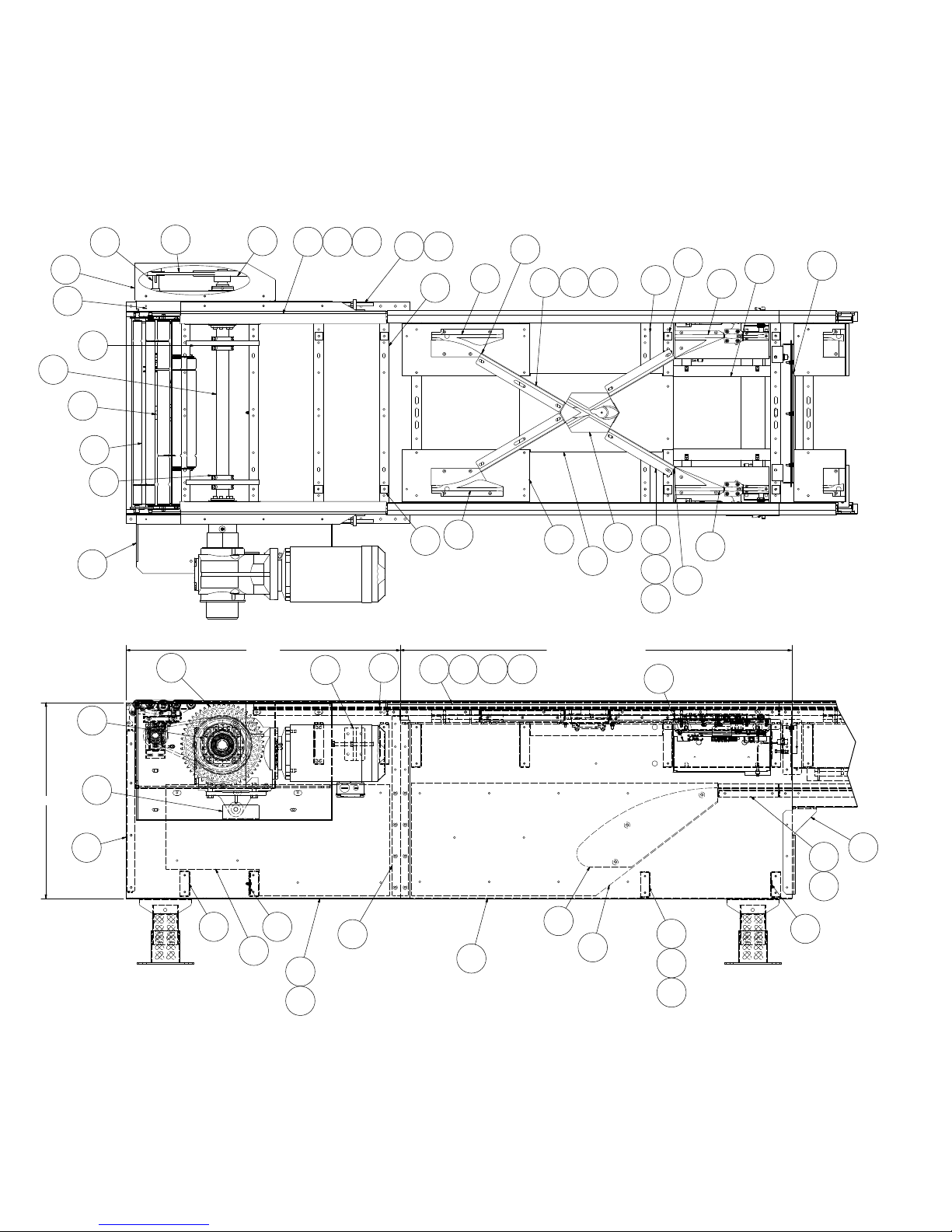
• Model ProSort 132 Elite Parts Drawing
Catenary Divert and Drive Section
(Sección de transmisión y desviación catenaria)
Dibujo de piezas del modelo ProSort 132 Elite
20
27
29
22
8
3
23
6
26
7
21
2
DRIVE
10
28
14
17
54
24
32
11
9
35
36
32
38
146
35 43 45
40
CATENARY DIVERT
133
49
33
24
35
42
44
39
11
146
52
51
54
134
1
16
19
25 148
15
12
13
18
48
34
46
30
31
55
25
37
50
47
30
26
Page 27
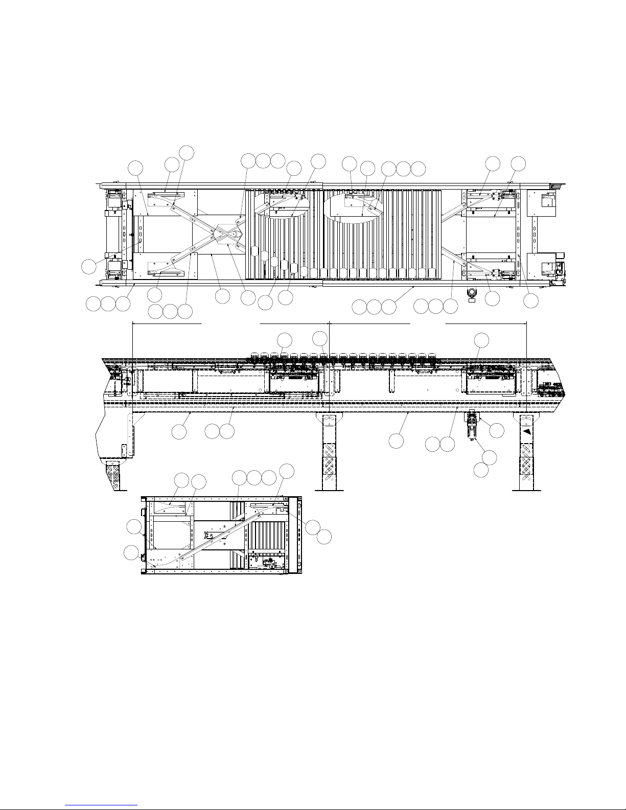
• Model ProSort 132 Elite Parts Drawing
Dual Divert and Divert Return
(Desviación doble y retorno de desviación)
Dibujo de piezas del modelo ProSort 132 Elite
146
32
45 43
32
49
35
DUAL DIVERT RETURN
67
41 37
60
59
35
40
24
38
41
36
4442
35
33
136
135
39
65
68
66
54
51
32
40
41
56
42
35
44
43
45
36
38
DUAL DIVERT
57
35
39
41 37
141
142
52
5451
24
143
64
58
61
62
DUAL DIVERT RETURN
BOTTOM VIEW
SCALE: NONE
NOTE:
Place chain covers so that no
seams are located within the spur/
diverting area.
NOTA:
Coloque las cubiertas de cadena para
que no haya empalmes en el área de
desvío con la espuela.
27
Page 28
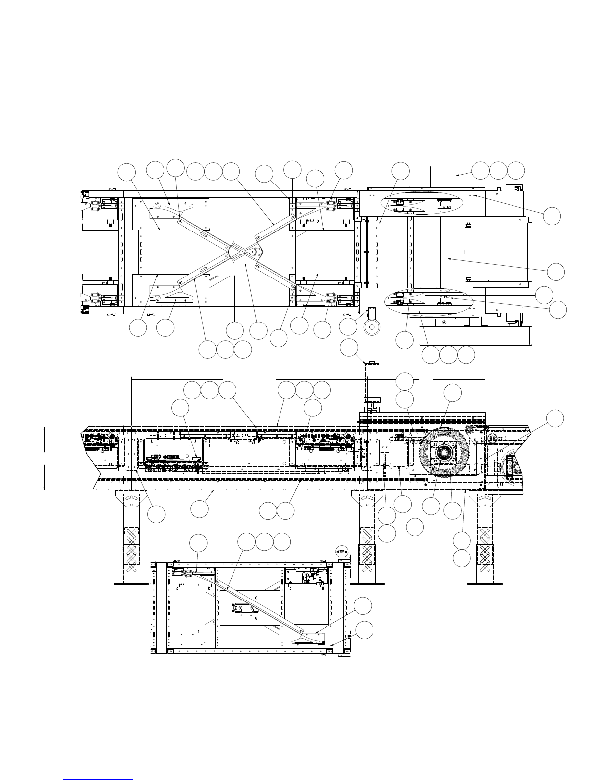
• Model ProSort 132 Elite Parts Drawing
Dual Divert Return Switch & Tail
(Retorno e interruptor de retorno de desviación doble)
Dibujo de piezas del modelo ProSort 132 Elite
16
SIDE ANGLE
40
32
146
44
3240
3542
35 43
RETURN SWITCH
137138139
3349
45
DUAL DIVERT
53
146
11
54
36 38
51
54
72
52
70
41
3939
53
69
82
73
TAIL
74
83 84
87 140
86
144
88
78
8
6
76
64
DUAL DIVERT RETURN SWITCH
BOTTOM VIEW
SCALE: NONE
67
52
35 65 66
4163
32
40
75
71
77
81
1
21
79
80
28
Page 29
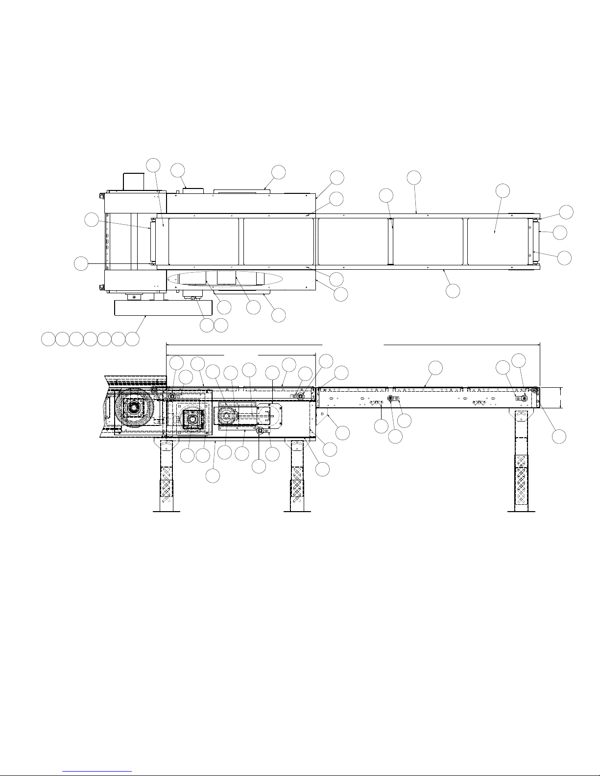
• Model ProSort 132 Elite Parts Drawing
Induction Unit
(Unidad de inducción)
112
120
105
117
109
106
Dibujo de piezas del modelo ProSort 132 Elite
131
124
122
123
105
111
125
106
109
101121
118
116115
919394113114119
92
INFEED BELT
97
100
95
96
90
102
89
99
110
DRIVE
118
104
100
98
96
97
INFEED INDUCTION BELT
97
96
108
107
103
132
130
128
129
131
127
129124
6 1/2
126
29
Page 30
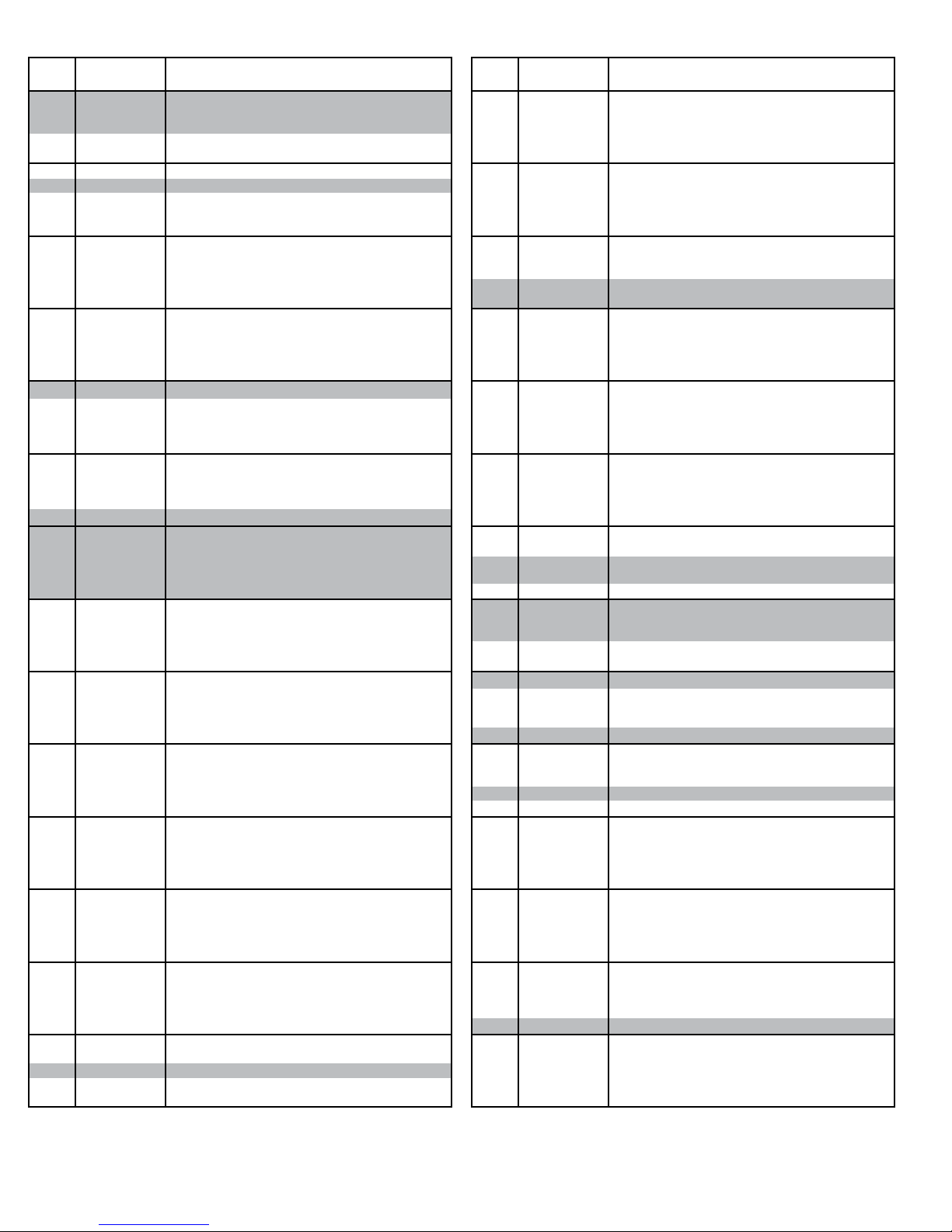
• Model ProSort 132 Elite Parts List
Ref.
Part No. Description
No.
1
927.0360
2
020.150
3
032.2116
4
040.409
5
041.201
6
SA-077155
7
375.03625
8
932.0187
9
MP-002368
10
PT-098832-252
11
PT-142073
12
PT-144001
13
PT-144126
14
PT-145273
15
PT-145274
16
PT-145302
17
PT-145575
18
PT-145702
19
-
20
-
21
SA-063930
22
SA-066115
23
SA-068320
24
WA-040985
25
WA-040986
26
WA-041274
27
WA-041284
28
WA-041286
29
WA-041373
30
033.2130
31
033.2131
32
-
-
092.1785
-
092.1795
33
923.0207
34
MP-002572
35
MP-002356
36
-
37
-
38
-
39
-
40
-
41
-
42
-
43
-
44
-
45
-
46
-
47
-
48
-
-
-
-
-
-
-
-
-
49
-
50
-
51
SA-061764
52
SA-066648
53
-
54
-
55
-
56
-
57
-
-
-
-
-
-
-
-
-
58
092.18051
59
B-23847
60
MP-002544
Bearing - Cast Iron, 4-bolt, 1-15/16" bore
Sheave - 1A, 8.95"OD X 1-1/2" bore
Proximity Switch
1/2-13 x 6"lg. Hex Bolt, full thread
1/2-13 Hex Jam Nut
Cushion Disk Assembly PS100E
O-ring - Orange, 3/8" diameter
Cushion Disk - 3/4" wide X 11-1/8"OD X 1.945" Bore
Chain Guide Wearstrip - Bottom
Belt Brush - 31-1/2"lg.
Pin Guide Spacer
Side Angle- Drive, Inside (LH or RH)
Side Angle- Drive, Outside (LH or RH)
Chain Wearstrip Angle - Drive
Drive Catenary Wearstrip
End Cover - Drive
Brush Holder - 31-1/2"lg. (LH or RH)
Joint Splice Plate - Drive
T orque Arm Bracket
Drive Shaft (specify OAW)
Sprocket Assembly
Transition Drive Assembly (LH or RH)
Transition Roller Assembly (specify OAW)
Bed Spacer Weldment (specify OAW)
Bed Spacer Weldment - Catenary, Lower (specify OAW)
Drive Bearing Mounting Channel Weldment (LH or RH)
Guard Weldment
Take-up Weldment
Drive Bearing Mounting Channel Weldment (LH or RH)
Photoeye - Retro-Reective, 10-40VDC
Photoeye Mounting Bracket - Ball Swivel
Y-Block
Y-Block - LH, 30°
Y-Block - RH, 30°
Manual Center Switch Assembly - 30°
Catenary Block
UHMW Wearstrip - J-leg (specify length)
Chain Guide Wearstrip - Top (specify length)
Chain Guide Wearstrip - Bottom (specify length)
Chain Cover (specify length x 8)
Cover Plate Switch Side
Y-Block Support Plate
Chain Guide Mounting Angle
Divert Angle - Short (specify length)
Divert Angle - Long (specify length)
Wearstrip Tie Strap - Short
Wearstrip Tie Strap - Long
Catenary Wearstrip (Side)
End Plate for Catenary (specify OAW)
Side Angle - Catenary
60 inch long, for 31"OAW 30° (LH or RH)
69 inch long, for 37"OAW 30° (LH or RH)
81 inch long, for 43"OAW 30° (LH or RH)
90 inch long, for 49"OAW 30° (LH or RH)
Center Divert Switch Mounting Channel
Chain Wearstrip Angle
30 ° Pneumatic Switch Assembly - LH
30° Pneumatic Switch Assembly - RH
Bed Spacer Weldment
Switch Support Channel Weldment
Photo-eye Channel Weldment - Catenary, Lower
Splice Plate
Side Angle - Dual Divert Section
60 inch long, for 31"OAW 30° (LH or RH)
69 inch long, for 37"OAW 30° (LH or RH)
81 inch long, for 43"OAW 30° (LH or RH)
90 inch long, for 49"OAW 30° (LH or RH)
Sweep Block - 30°
Pin Guide Block Plate
Pin Guide
Ref.
No.
61
62
63
64
65
66
67
-
-
-
68
69
70
71
72
73
74
75
76
77
78
79
80
81
82
83
84
85
86
87
88
89
90
91
92
93
94
95
96
97
98
99
100
101
102
103
104
105
106
107
108
109
110
111
112
113
114
115
116
117
118
119
120
121
122
123
124
-
-
Lista de piezas del modelo ProSort 132 Elite
Part No. Description
092.17855
092.17955
-
-
-
-
-
-
-
-
SA-073869
MP-002583
095.150
095.155
B-18450
MP-002345
PT-098832-256
PT-126624
PT-157654
PT-141808
PT-141809
PT-141810
PT-141811
PT-141994
PT-141996
PT-145267
PT-145270
PT-145325
PT-167701
SA-073294
WA-040390
010.203
010.2045
049.310
108.038327
108.056324
108.813603
B-04655
PT-167770
B-15299
B-23159
B-23162
B-23294
B-23296
B-23297
B-23299
B-23302
B-23575
PT-167742
PT-145144
PT-157665
PT-145147
PT-145156
PT-145175
PT-145227
PT-167436
PT-167440
PT-167463
PT-167464
PT-167697
PT-167711
PT-167786
SA-072835
SA-072717
B-23585
B-23578
B-22241
B-22242
Y-Block RH, 30° Return
Y-Block LH, 30° Return
Chain Guide Wearstrip - Bottom
Y-Block Support Plate, Return
Divert Angle
Wearstrip Tie Strap
Side Angle - Dual Divert Section
60 inch long, for 31"OAW 30° (LH or RH)
69 inch long, for 37”OAW 30° (LH or RH)
81 inch long, for 43”OAW 30° (LH or RH)
90 inch long, for 49"OAW 30° (LH or RH)
Lost Pin Prox Assembly (22° or 30° & LH or RH)
Infeed Guide
Chain Lubricator w/2 feeds
Shank Brush for Chain Lubricator
Oiler Mount Bracket
Chain Guide Wearstrip - Tail
Belt Brush - 32”lg.
Cover Plate
End Channel - Dual Tail (specify OAW)
Oiler Support Bracket
Tail Shaft (specify OAW)
Tail Channel - LH, 30”lg.
Tail Channel - RH, 30”lg.
Bearing Spacer Plate
Chain Wearstrip Angle - Tail
Brush Holder - 32"lg.
Brush Holder - Right Angle
Infeed Guide Plate
Drive Shaft Slot Cover
Bearing Cover Kit
End Cover Weldment (specify LH or RH)
Bearing - Cast Iron, 4-bolt, 1-7/16” bore
Bearing - Cast Iron, 4-bolt, 1-11/16” bore
1/4-20 U-type Speed Nut
Timing Belt Sprocket - 38PTH8-35SH X 1-11/16"Bore
Timing Belt Sprocket - 56PTH8-35SK X 1-1/2"Bore
Timing Belt - 1360PTH8M-35
Bearing Guide Spacer - Take-up pulley
11/16” Hex Idler Mounting Bracket
25 Heavy Duty Snub Idler (specify OAW)
Cover Weldment
Pulley Plate Weldment
Slider Pan - 22-1/2”lg (specify OAW)
6”Dia. Take-up Pulley Weldment (specify OAW)
Take-up Plate Weldment - 6" Take-up Pulley
Butt Coupling Angle (specify LH or RH)
Take-up Bolt Weldment
2-1/4” Dia. Pulley Assembly (specify OAW)
Induction Drive Channel (Specify LH or RH)
Drive Side Plate (specify LH or RH)
Drive End Channel - Dual (specify OAW)
Top Drive Cover - Slave Side
Bottom Drive Guard (specify OAW)
Pulley Mounting Bracket
Nip Point Guard
Slave Guard Mounting Bracket
Slave Guard (specify LH or RH)
Bearing Extend Channel - Induction Drive
Bearing Flange Cover - Induction Drive
Take-up Bearing Cover
Bearing Guide - Take-up Pulley
Slave Guard Cover
Bearing Cover Kit
8”Dia. Center Drive Pulley (specify OAW)
Belt Kit (specify BR and section length)
Pulley Mount
Bolt-in Pan (specify BR)
16-1/2” long
19-1/2” long
30
Page 31
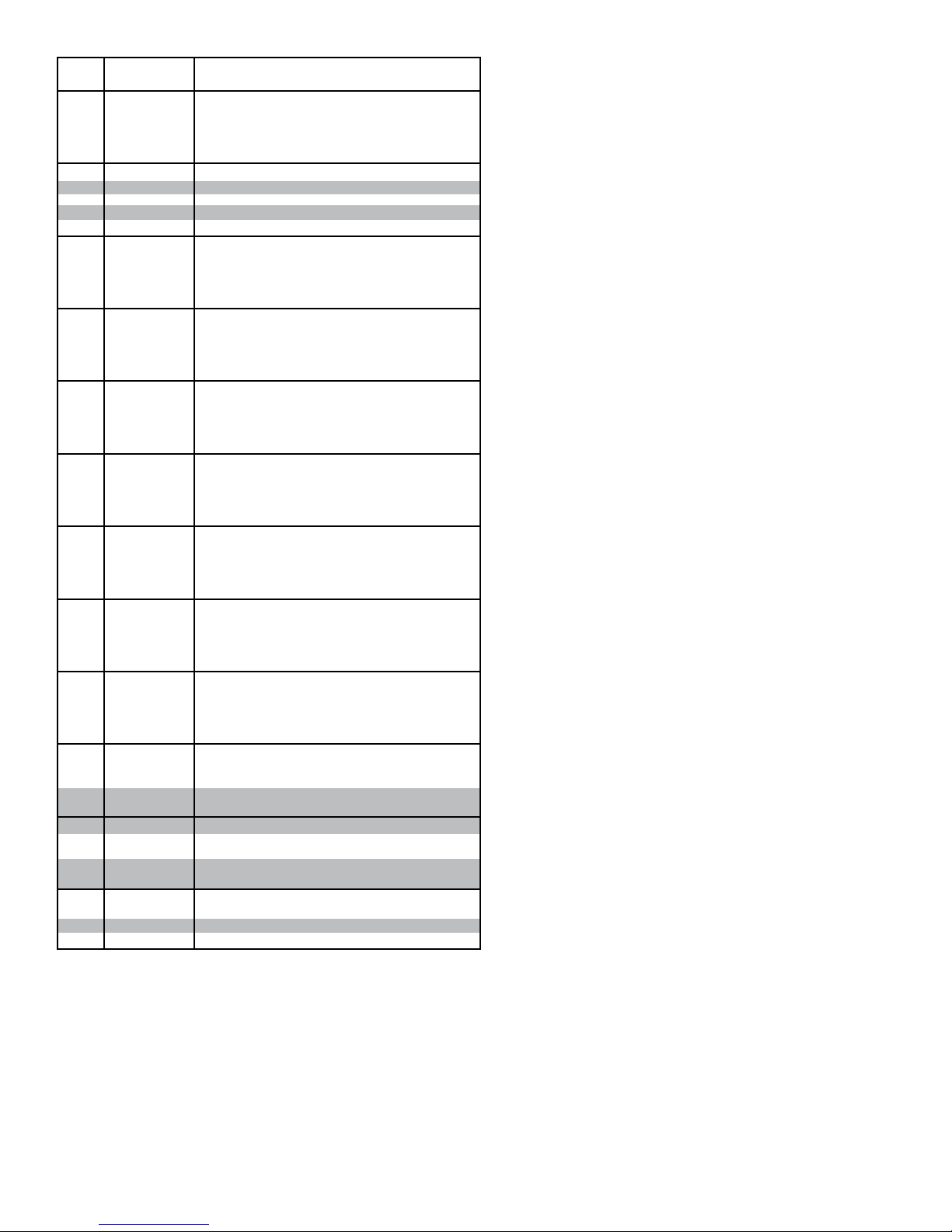
• Model ProSort 132 Elite Parts List
Ref.
Part No. Description
No.
-
-
-
125
126
127
128
129
130
131
-
-
-
-
-
-
-
-
-
-
-
-
-
-
-
-
-
-
-
-
-
-
-
-
-
-
-
-
-
-
-
-
132
133
134
135
136
137
138
139
140
141
142
143
144
145
146
B-22243
B-22244
B-22224
B-22245
B-23579
B-03191
B-03894
B-00944
B-01982
B-03916
B-21500
B-21501
B-21502
B-21170
B-21503
B-21504
B-21505
B-21506
B-04923
B-21507
B-21508
B-21509
B-02636
B-23308
B-23309
B-23310
B-05494
B-23311
B-23312
B-23313
B-21606
B-23314
B-12082
B-23315
B-09908
B-23568
B-23569
B-23570
B-21607
B-23571
B-23572
B-23573
B-02633
B-23581
069.7501
SA-063997
SA-061763
092.1857
029.2658
029.2666
011.1004
PT-089907
094.1912
094.190
B-11302
032.293
032.2185
PT-174779
22-1/2" long
25-1/2" long
28-1/2” long
31-1/2” long
Nip Point Guard (specify BR)
Butt Coupling Angle
2-1/8"OD Roller Assembly (specify BR)
7/16” Hex Idler Bracket
1.9”OD Galvanized Roller Assembly (specify BR)
Bed Spacer (specify BR)
Side Channel
2 ft. Long
2 ft. 3 in. Long
2 ft. 6 in. Long
2 ft. 9 in. Long
3 ft. Long
3 ft. 3 in. Long
3 ft. 6 in. Long
3 ft. 9 in. Long
4 ft. Long
4 ft. 3 in. Long
4 ft. 6 in. Long
4 ft. 9 in. Long
5 ft. Long
5 ft. 3 in. Long
5 ft. 6 in. Long
5 ft. 9 in. Long
6 ft. Long
6 ft. 3 in. Long
6 ft. 6 in. Long
6 ft. 9 in. Long
7 ft. Long
7 ft. 3 in. Long
7 ft. 6 in. Long
7 ft. 9 in. Long
8 ft. Long
8 ft. 3 in. Long
8 ft. 6 in. Long
8 ft. 9 in. Long
9 ft. Long
9 ft. 3 in. Long
9 ft. 6 in. Long
9 ft. 9 in. Long
10 ft. Long
Gussett Angle (specify LH or RH)
Bearing Prole
Saftey Switch Assembly (specify OAW)
Slat Assembly (specify OAW)
Divert Shoe
#60XLO Riveted O-ring Chain
Connector Link - #60XLO Chain
Bearing - Single row radial
Encoder Cover
Pressure Switch
Filter Regulator
Mounting Angle - Filter/Reg. Kit
Encoder Kit - 30PPR
Reector - 3.30” dia.
Divert Angle Alignment Block
Lista de piezas del modelo ProSort 132 Elite
31
Page 32
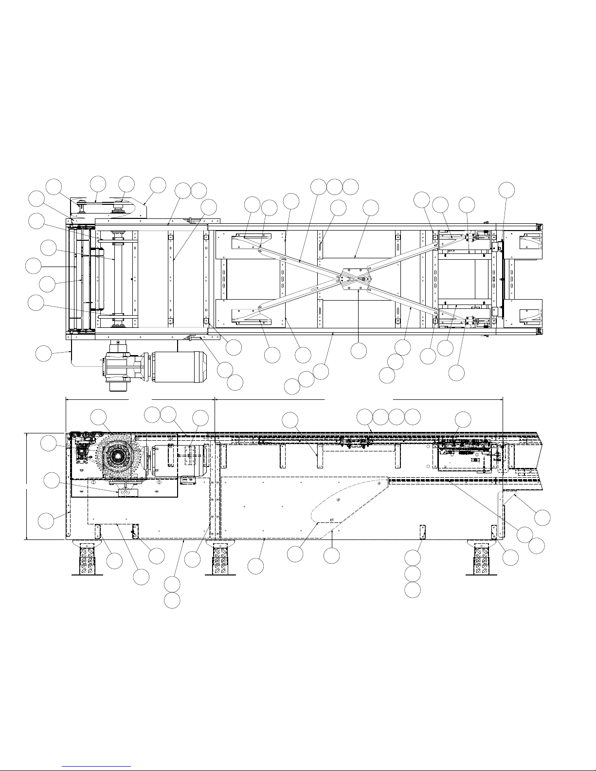
• Model ProSort 122 Elite Parts Drawing
Catenary Divert and Drive Section
(Sección de transmisión y desviación catenaria)
7
2
22
29
8
20
23
3
6
27
10 17
24
32
146
35 43 45
40
Dibujo de piezas del modelo ProSort 122 Elite
134
53
51
24
49
54
26
DRIVE
9
15
14
145
28
18
12
13
21
1
19
30
16
25
11
4
5
48
32
24
50
34
40
36
38
CATENARY DIVERT
33
35
46
36
44
42
38
35
133
30
31
55
54
146
52
39
47
37
50
25
32
Page 33
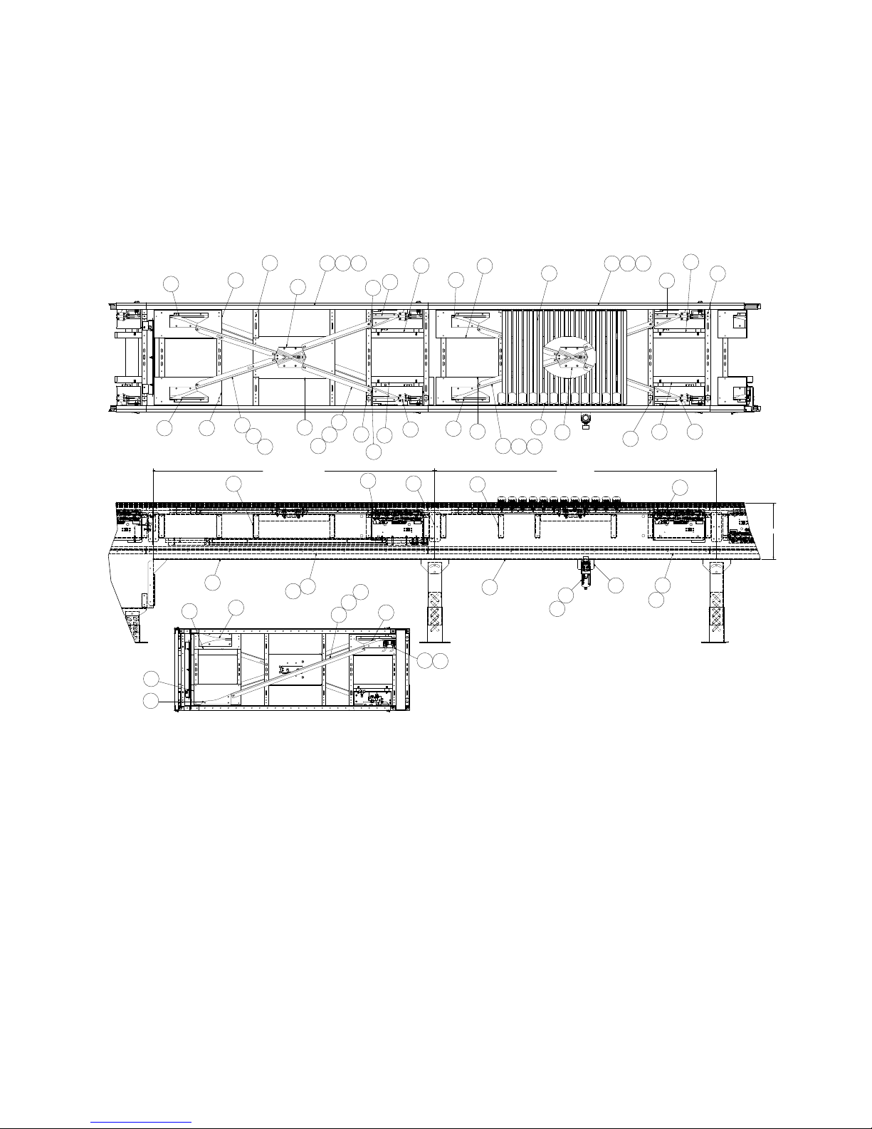
• Model ProSort 122 Elite Parts Drawing
Dual Divert and Divert Return
(Desviación doble y retorno de desviación)
Dibujo de piezas del modelo ProSort 122 Elite
24
32
59
64
58
40
35
4032
43
45
DUAL DIVERT RETURN
24
67
60
36 38 50
33
49
44
37
41
146
35
11
42
146
39
66
65
35
51
54
68
54
32
32
52
56
61
62
DUAL DIVERT RETURN
BOTTOM VIEW
SCALE: NONE
40
40
35
24
57
135
136
43
33
45
DUAL DIVERT
141
142
36 38 41
53
143
54
51
54
37
41
11
52
39
16
NOTE:
Place chain covers so that no
seams are located within the spur/
diverting area.
NOTA:
Coloque las cubiertas de cadena para
que no haya empalmes en el área de
desvío con la espuela.
33
Page 34
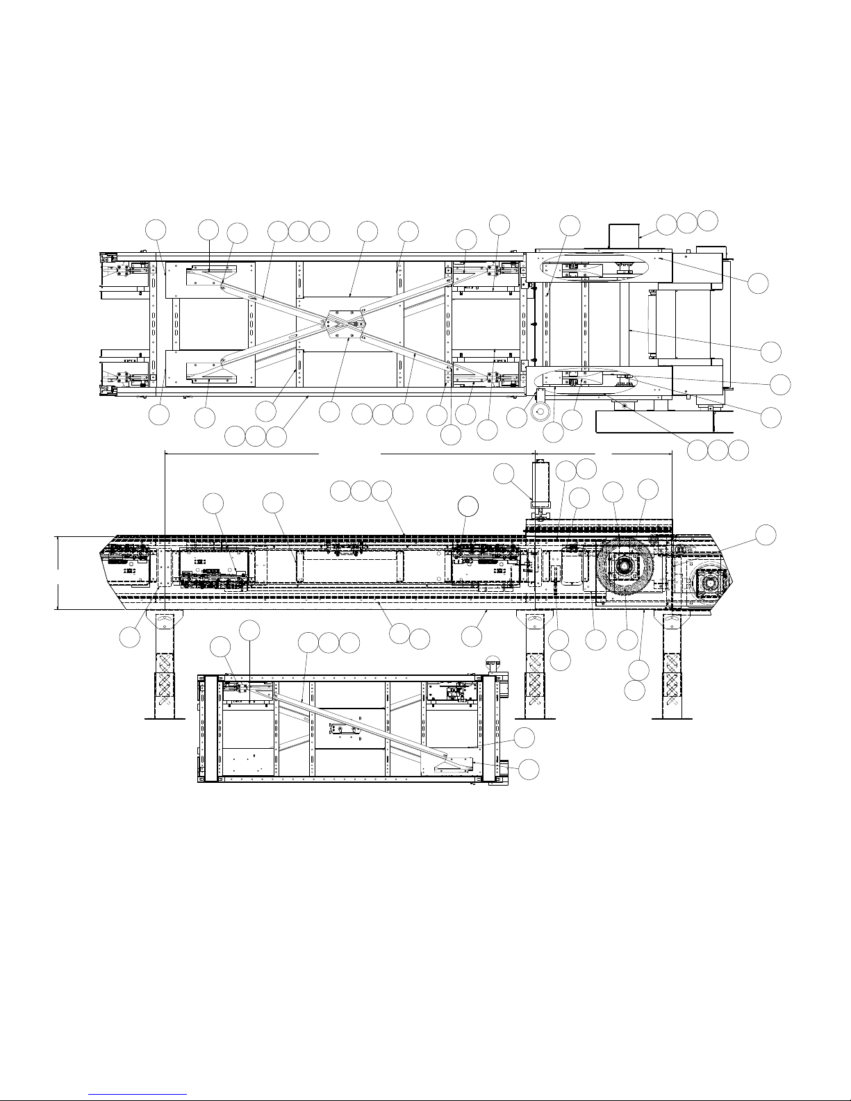
• Model ProSort 122 Elite Parts Drawing
Dual Divert Return Switch & Tail
(Retorno e interruptor de retorno de desviación doble)
3240
146
244935 43 45
Dibujo de piezas del modelo ProSort 122 Elite
144
54
51
24
140
87
88
78
8
40
16
SIDE ANGLE
56
DUAL DIVERT RETURN SWITCH
BOTTOM VIEW
SCALE: NONE
32
39
52
24
3841
36
24
54
33
DUAL DIVERT
RETURN SWITCH
35
65 66
35
44
42
137138139
41
63
52
53
146
39
39
67
72
54
70
40
32
69
85
74
TAIL
82
73
1
86
75
218171
77
79
80
83 84
6
76
34
Page 35
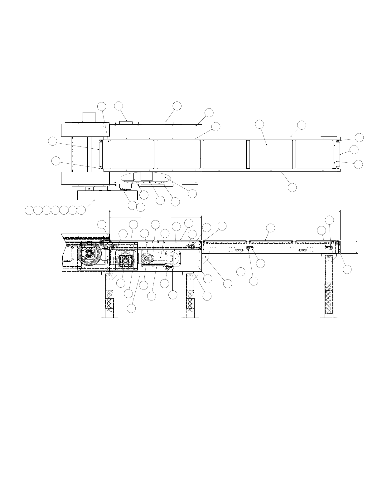
• Model ProSort 122 Elite Parts Drawing
Induction Unit
(Unidad de inducción)
Dibujo de piezas del modelo ProSort 122 Elite
101
104
97
96
117
117120
109
106
97
INFEED INDUCTION BELT
100
98
96
97
108
107
103
132
122
124
128
130
129
131
123
105
125
131
127
128
6 1/2
126
112
105
111
121
115
113
114119
91929394
97
90
116
INFEED BELT DRIVE
102100
96
95
89
99
118
110
35
Page 36
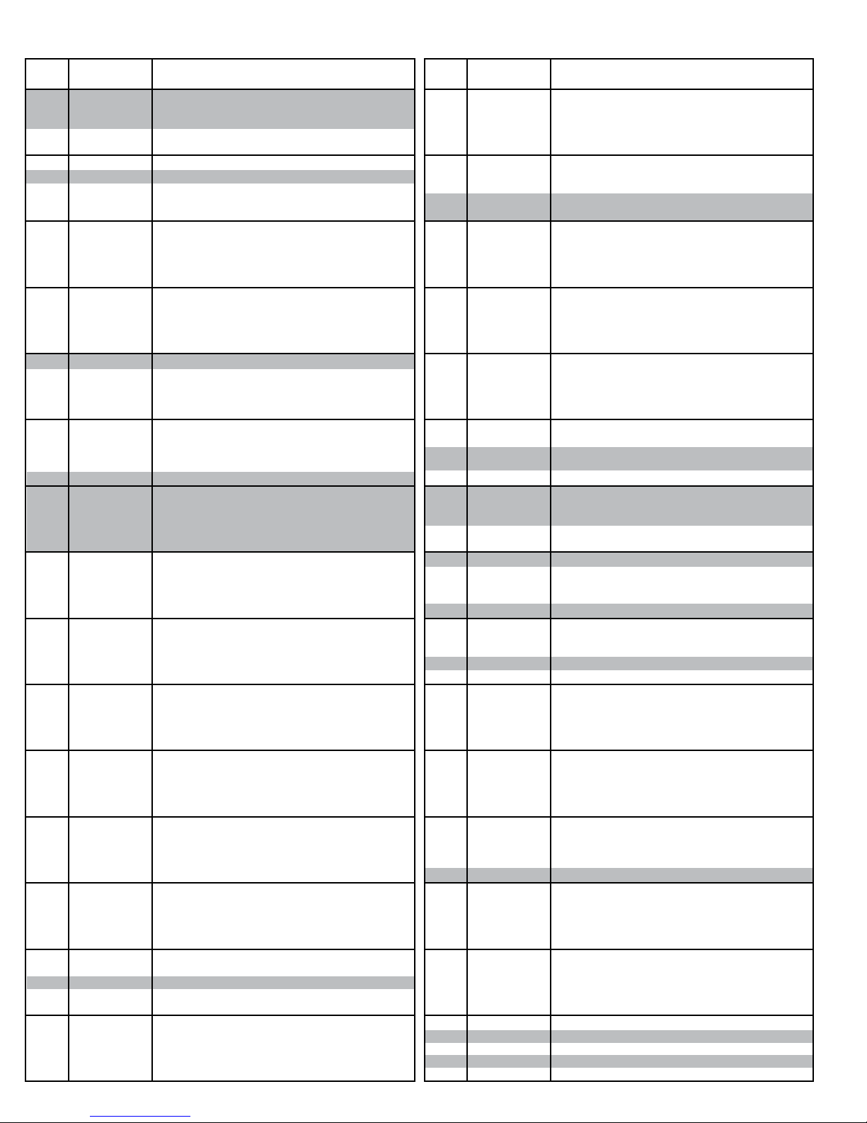
• Model ProSort 122 Elite Parts List
Ref.
Part No. Description
No.
1
927.0360
2
020.150
3
032.2116
4
040.409
5
041.201
6
SA-077155
7
375.03625
8
932.0187
9
MP-002368
10
PT-098832-252
11
PT-142073
12
PT-144001
13
PT-144126
14
PT-145273
15
PT-145274
16
PT-145302
17
PT-145575
18
PT-145702
19
-
20
-
21
SA-063930
22
SA-066115
23
SA-068320
24
WA-040985
25
WA-040986
26
WA-041274
27
WA-041284
28
WA-041286
29
WA-041373
30
033.2130
31
033.2131
32
-
-
092.1782
-
092.1792
33
923.0208
34
MP-002572
35
MP-002356
36
-
37
-
38
-
39
-
40
-
41
-
42
-
43
-
44
-
45
-
46
-
47
-
48
-
-
-
-
-
-
-
-
-
49
-
50
-
51
SA-067120
52
SA-067121
53
-
54
-
55
-
56
-
57
-
-
-
-
-
-
-
-
-
58
MP-002593
59
B-23847
60
MP-002544
61
092.1783
62
092.1793
63
-
64
-
65
-
Bearing - Cast Iron, 4-bolt, 1-15/16" bore
Sheave - 1A, 8.95"OD X 1-1/2" bore
Proximity Switch
1/2-13 x 6"lg. Hex Bolt, full thread
1/2-13 Hex Jam Nut
Cushion Disk Assembly PS100E
O-ring - Orange, 3/8" diameter
Cushion Disk - 3/4" wide X 11-1/8"OD X 1.945" Bore
Chain Guide Wearstrip - Bottom
Belt Brush - 31-1/2"lg.
Pin Guide Spacer
Side Angle- Drive, Inside (LH or RH)
Side Angle- Drive, Outside (LH or RH)
Chain Wearstrip Angle - Drive
Drive Catenary Wearstrip
End Cover - Drive
Brush Holder - 31-1/2"lg. (LH or RH)
Joint Splice Plate - Drive
T orque Arm Bracket
Drive Shaft (specify OAW)
Sprocket Assembly
Transition Drive Assembly (LH or RH)
Transition Roller Assembly (specify OAW)
Bed Spacer Weldment (specify OAW)
Bed Spacer Weldment - Catenary, Lower (specify OAW)
Drive Bearing Mounting Channel Weldment (LH or RH)
Guard Weldment
Take-up Weldment
Drive Bearing Mounting Channel Weldment (LH or RH)
Photoeye - Retro-Reective, 10-40VDC
Photoeye Mounting Bracket - Ball Swivel
Y-Block
Y-Block - LH, 22°
Y-Block - RH, 22°
Manual Center Switch Assembly - 22°
Catenary Block
UHMW Wearstrip - J-leg (specify length)
Chain Guide Wearstrip - Top (specify length)
Chain Guide Wearstrip - Bottom (specify length)
Chain Cover (specify length x 8)
Cover Plate Switch Side
Y-Block Support Plate
Chain Guide Mounting Angle
Divert Angle - Short (specify length)
Divert Angle - Long (specify length)
Wearstrip Tie Strap - Short
Wearstrip Tie Strap - Long
Catenary Wearstrip (Side)
End Plate for Catenary (specify OAW)
Side Angle - Catenary
81 inch long, for 31"OAW 22° (LH or RH)
96 inch long, for 37"OAW 22° (LH or RH)
111 inch long, for 43"OAW 22° (LH or RH)
126 inch long, for 49"OAW 22° (LH or RH)
Center Divert Switch Mounting Channel
Chain Wearstrip Angle
22 ° Pneumatic Switch Assembly - LH
22° Pneumatic Switch Assembly - RH
Bed Spacer Weldment
Switch Support Channel Weldment
Photo-eye Channel Weldment - Catenary, Lower
Splice Plate
Side Angle - Dual Divert Section
81 inch long, for 31"OAW 22° (LH or RH)
96 inch long, for 37"OAW 22° (LH or RH)
111 inch long, for 43"OAW 22° (LH or RH)
126 inch long, for 49"OAW 22° (LH or RH)
Sweep Block - 22°
Pin Guide Block Plate
Pin Guide
Y-Block RH, 22° Return
Y-Block LH, 22° Return
Chain Guide Wearstrip - Bottom
Y-Block Support Plate, Return
Divert Angle
Ref.
No.
66
67
-
-
-
68
69
70
71
72
73
74
75
76
77
78
79
80
81
82
83
84
85
86
87
88
89
90
91
92
93
94
95
96
97
98
99
100
101
102
103
104
105
106
107
108
109
110
111
112
113
114
115
116
117
118
119
120
121
122
123
124
-
-
-
-
-
125
126
127
128
129
130
Lista de piezas del modelo ProSort 122 Elite
Part No. Description
-
-
-
-
-
SA-073869
MP-002583
095.150
095.155
B-18450
MP-002345
PT-098832-256
PT-126624
PT-157654
PT-141808
PT-141809
PT-141810
PT-141811
PT-141994
PT-141996
PT-145267
PT-145270
PT-145325
PT-167701
SA-073294
WA-040390
010.203
010.2045
049.310
108.038327
108.056324
108.813603
B-04655
PT-167770
B-15299
B-23159
B-23162
B-23294
B-23296
B-23297
B-23299
B-23302
B-23575
PT-167742
PT-145144
PT-157665
PT-145147
PT-145156
PT-145175
PT-145227
PT-167436
PT-167440
PT-167463
PT-167464
PT-167697
PT-167711
PT-167786
SA-072835
SA-072717
B-23585
B-23578
B-22241
B-22242
B-22243
B-22244
B-22224
B-22245
B-23579
B-03191
B-03894
B-00944
B-01982
B-03916
Wearstrip Tie Strap
Side Angle - Dual Divert Section
81 inch long, for 31"OAW 22° (LH or RH)
96 inch long, for 37”OAW 22° (LH or RH)
111 inch long, for 43”OAW 22° (LH or RH)
126 inch long, for 49"OAW 22° (LH or RH)
Lost Pin Prox Assembly (Specify 22° or 30° & LH or RH)
Infeed Guide
Chain Lubricator w/2 feeds
Shank Brush for Chain Lubricator
Oiler Mount Bracket
Chain Guide Wearstrip - Tail
Belt Brush - 32”lg.
Cover Plate
End Channel - Dual Tail (specify OAW)
Oiler Support Bracket
Tail Shaft (specify OAW)
Tail Channel - LH, 30”lg.
Tail Channel - RH, 30”lg.
Bearing Spacer Plate
Chain Wearstrip Angle - Tail
Brush Holder - 32"lg.
Brush Holder - Right Angle
Infeed Guide Plate
Drive Shaft Slot Cover
Bearing Cover Kit
End Cover Weldment (LH or RH)
Bearing - Cast Iron, 4-bolt, 1-7/16” bore
Bearing - Cast Iron, 4-bolt, 1-11/16” bore
1/4-20 U-type Speed Nut
Timing Belt Sprocket - 38PTH8-35SH X 1-11/16"Bore
Timing Belt Sprocket - 56PTH8-35SK X 1-1/2"Bore
Timing Belt - 1360PTH8M-35
Bearing Guide Spacer - Take-up pulley
11/16” Hex Idler Mounting Bracket
25 Heavy Duty Snub Idler (specify OAW)
Cover Weldment
Pulley Plate Weldment
Slider Pan - 22-1/2”lg (specify OAW)
6”Dia. Take-up Pulley Weldment (specify OAW)
Take-up Plate Weldment - 6" Take-up Pulley
Butt Coupling Angle (LH or RH)
Take-up Bolt Weldment
2-1/4” Dia. Pulley Assembly (specify OAW)
Induction Drive Channel (LH or RH)
Drive Side Plate (LH or RH)
Drive End Channel - Dual (specify OAW)
Top Drive Cover - Slave Side
Bottom Drive Guard (specify OAW)
Pulley Mounting Bracket
Nip Point Guard (specify OAW)
Slave Guard Mounting Bracket
Slave Guard (LH or RH)
Bearing Extend Channel - Induction Drive
Bearing Flange Cover - Induction Drive
Take-up Bearing Cover
Bearing Guide - Take-up Pulley
Slave Guard Cover
Bearing Cover Kit
8”Dia. Center Drive Pulley (specify OAW)
Belt Kit (specify BR & section length)
Pulley Mount
Bolt-in Pan (specify BR)
16-1/2” long
19-1/2” long
22-1/2" long
25-1/2" long
28-1/2” long
31-1/2” long
Nip Point Guard
Butt Coupling Angle
2-1/8”OD Roller Assembly (specify BR)
7/16” Hex Idler Bracket
1.9”OD Galvanized Roller Assembly (specify BR)
Bed Spacer (specify BR)
36
Page 37
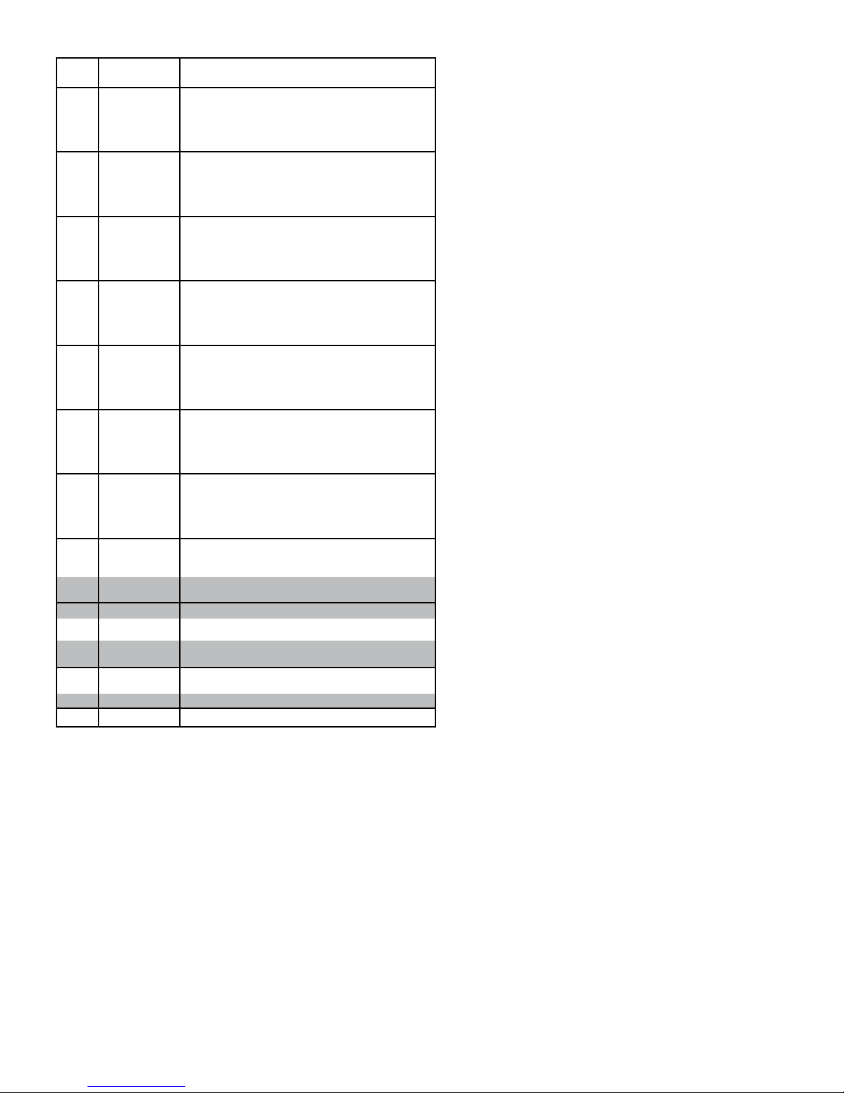
• Model ProSort 122 Elite Parts List
Lista de piezas del modelo ProSort 122 Elite
Ref.
No.
131
-
-
-
-
-
-
-
-
-
-
-
-
-
-
-
-
-
-
-
-
-
-
-
-
-
-
-
-
-
-
-
-
132
133
134
135
136
137
138
139
140
141
142
143
144
145
146 PT-174779 Divert Angle Alignment Block
Part No. Description
B-21500
B-21501
B-21502
B-21170
B-21503
B-21504
B-21505
B-21506
B-04923
B-21507
B-21508
B-21509
B-02636
B-23308
B-23309
B-23310
B-05494
B-23311
B-23312
B-23313
B-21606
B-23314
B-12082
B-23315
B-09908
B-23568
B-23569
B-23570
B-21607
B-23571
B-23572
B-23573
B-02633
B-23581
069.7501
SA-063997
SA-061763
092.1857
029.2658
029.2666
011.1004
PT-089907
094.1912
094.190
B-11302
032.293
032.2185
Side Channel
2 ft. Long
2 ft. 3 in. Long
2 ft. 6 in. Long
2 ft. 9 in. Long
3 ft. Long
3 ft. 3 in. Long
3 ft. 6 in. Long
3 ft. 9 in. Long
4 ft. Long
4 ft. 3 in. Long
4 ft. 6 in. Long
4 ft. 9 in. Long
5 ft. Long
5 ft. 3 in. Long
5 ft. 6 in. Long
5 ft. 9 in. Long
6 ft. Long
6 ft. 3 in. Long
6 ft. 6 in. Long
6 ft. 9 in. Long
7 ft. Long
7 ft. 3 in. Long
7 ft. 6 in. Long
7 ft. 9 in. Long
8 ft. Long
8 ft. 3 in. Long
8 ft. 6 in. Long
8 ft. 9 in. Long
9 ft. Long
9 ft. 3 in. Long
9 ft. 6 in. Long
9 ft. 9 in. Long
10 ft. Long
Gussett Angle (LH or RH)
Bearing Prole
Saftey Switch Assembly (specify OAW)
Slat Assembly (specify OAW)
Divert Shoe
#60XLO Riveted O-ring Chain
Connector Link - #60XLO Chain
Bearing - Single row radial
Encoder Cover
Pressure Switch
Filter Regulator
Mounting Angle - Filter/Reg. Kit
Encoder Kit - 30PPR
Reector - 3.30” dia.
37
Page 38
ÍNDICE
Hytrol Conveyor
Company, Inc.
JONESBORO, ARKANSAS
SERIAL # 123456
YEAR
QR
CODE
INTRODUCCION
Recepción y Desembalaje ...........................38
Como Ordenar Partes de Repuesto ....................38
INFORMACIÓN DE SEGURIDAD ........................38, 39
INSTALACION
Localización.......................................39
Montaje .......................................39, 40
Equipo Eléctrico ...................................41
OPERACION
Arranque del Transportador ..........................41
MANTENIMIENTO
Lubricación .......................................41
Ajuste del Cepillo del Engrasador ......................41
Controlando el ProSort .....................41, 42, 43, 44
Revisión del Interruptor Desviador Neumático ............44
Revisión del Interruptor Desviador Eléctrico ..............44
Instalación de Cadenas..............................45
Instalando las Guardas en Puntos Desviadores...........45
Ubicando las Espuelas ..............................45
Procedimiento de Desmontaje del
Interruptor del Desviador Neumático ...................46
Procedimiento de Desarmado del Interruptor
Desviador Eléctrico .................................46
Procedimiento para Iniciar Eesviador Eléctrico ...........47
Resolviendo Problemas .............................47
Lista del Plan de Mantenimiento ................Back Cover
REPLACEMENT PARTS
Conjunto de sensor de proximidad de pasador perdido
Lista y dibujo de piezas .............................11
Conjunto de interruptor de desviación neumático
Lista y dibujo de piezas..............................12
Conjunto de interruptor de desviación eléctrico
Lista y dibujo de piezas..............................13
Conjunto de interruptor de seguridad
Lista y dibujo de piezas..............................13
Dibujos de piezas de ProSort 131
Sección de transmisión, desviación de retorno y
desviación catenaria . . . . . . . . . . . . . . . . . . . . . . . . . . . . . . . . 14
Sección de retorno y desviación intermedia..............15
Unidad de inducción ...............................16
Conjunto de sección intermedia .......................17
Sección de desviación de 30° .........................17
Lista de piezas de ProSort 131.....................18, 19
Dibujos de piezas de ProSort 121
Sección de transmisión, desviación de retorno y
desviación catenaria . . . . . . . . . . . . . . . . . . . . . . . . . . . . . . . . 20
Sección de retorno y desviación intermedia .............21
Unidad de inducción ................................22
Conjunto de sección intermedia .......................23
Sección de desviación de 22° .........................23
Lista de piezas de ProSort 121.....................24, 25
Dibujos de piezas de ProSort 132
Sección de transmisión y desviación catenaria ...........26
Desviación doble y retorno de desviación ...............27
Retorno e interruptor de retorno de desviación doble ......28
Unidad de inducción ...............................29
Lista de piezas de ProSort 132.....................30, 31
Dibujos de piezas de ProSort 122
Sección de transmisión y desviación catenaria ...........32
Desviación doble y retorno de desviación ...............33
Retorno e interruptor de retorno de desviación doble ......34
Unidad de inducción ...............................35
Lista de piezas de ProSort 122 ....................36, 37
INTRODUCCIÓN
Este manual proporciona información para instalar, operar y dar mantenimiento a su
transportador. Se proporciona una lista completa de partes, con el refaccionamiento
recomendado resaltado en gris. T ambién se proporciona información importante de
seguridad a lo largo de este manual. Para seguridad del personal y para un mejor
funcionamiento del transportador, se recomienda que se lean y se sigan cada una
de las instrucciones proporcionadas en este manual.
• Recepción y Desembalaje
1. Verique el número de partes recibidas con respecto al conocimiento del
embarque.
2. Examine las condiciones del equipo para determinar si algún daño ha ocurrido
durante el transporte.
3. Traslade todo el equipo al área de instalación.
4. Remueva todos los empaques y verique si hay partes adicionales que puedan
estar sujetas al equipo. Asegúrese de que estas partes (u otras partes ajenas al
equipo) sean removidas.
NOTA: Si algún daño ha ocurrido o faltan partes, contacte a su integrador
Hytrol.
• Cómo Ordenar Refaccionamiento
En este manual encontrará dibujos de las partes con listas completas de las
refacciones. Partes pequeñas, como tornillos y tuercas no están incluidos. Para
ordenar refaccionamiento:
1. Contacte al representante que le vendió el transportador o el distribuidor de
Hytrol más cercano.
2. Proporcione el Modelo del Transportador y el Número de Serie o Número
de la Orden de Fabricación.
3. Proporcione el Número de las partes y descripción completa que aparece
en la Lista de Partes.
4. Si su equipo se encuentra en una situación crítica, comuníquese con nosotros
inmediatamente.
Refaccionamiento Recomendado se Resalta en Gris
Número de Serie HYTROL
(Localizado cerca de la Unidad Motriz en Modelos motorizados).
INFORMACIÓN DE SEGURIDAD
• Instalación
PROTECCIÓN Y SEGURIDAD
Interfaz de los equipos. Cuando dos o más piezas de equipo son interconectadas,
se deberá prestar especial atención a la zona de la interfaz para asegurar la
presencia de guardas y dispositivos de seguridad adecuados.
Localización o posición. Para procurar la protección de los trabajadores ante
los riesgos, todas las partes móviles expuestas de la maquinaria deberán ser
aseguradas mecánica o eléctricamente, o protegidas mediante el cambio de
localización o posición.
La presencia alejada del público o empleado constituirá una medida de seguridad
por ubicación.
Cuando el transportador esté instalado sobre pasillos, corredores o estaciones de
trabajo; se considera protegido únicamente por localización o posición si todas las
partes en movimiento están mínimo a 8 pies (2,44 m) por encima del piso o área
de tránsito. De otra manera se pueden ubicar de tal manera que los empleados no
entren en contacto con partes móviles peligrosas sin querer.
Aunque los transportadores aéreos pueden estar protegidos por su ubicación,
deben proporcionarse guardas para evitar derrames: guardas laterales e inferiores;
Esto si el producto pued e caerse del transportador y así mantener al personal
fuera de peligro.
ESPACIO LIBRE SUPERIOR
Cuando los transportadores son instalados sobre pasillos, salidas o corredores; se
deberá disponer de un espacio libre mínimo de 6 pies 8 pulgadas (2,032 m), medido
verticalmente desde el suelo o mezanine a la parte más baja del transportador o
de las guardas
Cuando el funcionamiento del sistema sea afectado al guardar la distancia
mínima de 6 pies 8 pulgadas (2,032 m), deberán autorizarse pasillos alternos de
emergencia.
Es posible permitir el paso bajo transportadores con menos de 6 pies 8 pulgadas
(2.032 m) desde el piso, con excepción de las salidas de emergencia. Para esto se
requiere una señalización apropiada que indique altura baja.
38
Page 39

• Operación
FLOW
MATCH MARK NUMBERS
(ETIQUETAS DE SCUENCIA DE ARMADO)
KNEEBRACE
(SOPORTE ANGULAR)
INTERMEDIATE SUPPORT
(SOPORTE INTERMEDIOS)
DRIVE SUPPORT
(SOPORTE MOTRIZ)
DRIVE
(MOTOR)
CATENARY DIVERT
(DESVIACION CATENARIA)
RETURN DIVERT
(DESVIACION DE RETORNO)
INTERMEDIATE DIVERT
(DESVIACION INTERMEDIA)
TAIL
(RETORNO)
INFEED BELT DRIVE
(BANDA ALIMENTADORA
MOTRIZ)
INFEED INDUCTION BELT
(BANDA ALIMENTADORA DE INDUCCION)
5D
5A
4D
5B
4C 4E
4B 5C
FO:
MARK:
TOOL BOX
QR
CODE
H
Y
T
R
O
L
C
O
D
E
MODEL
A
FO:
MARK:
TOOL BOX
QR
CODE
H
Y
T
R
O
L
C
O
D
E
MODEL
A
(FLUJO)
A) Sólo los empleados capacitados están autorizados a operar los transportadores.
El entrenamiento debe incluir: operación bajo condiciones normales y en
situaciones de emergencia.
B) Cuando la seguridad de los trabajadores dependa de dispositivos de paro
y/o arranque, tales dispositivos deben mantenerse libres de obstrucciones para
permitir un acceso rápido.
C) El área alrededor de los puntos de carga y descarga deberá mantenerse libre de
obstrucciones que puedan poner en peligro al personal.
D) Ninguna persona podrá viajar en el elemento de carga de un transportador
sin excepción; al menos que esta persona esté especícamente autorizado por el
propietario o el empleador. En esas circunstancias, el empleado deberá montarse
solamente en un transportador que tenga incorporado en sus plataformas de
estructura de soporte o estaciones de control especialmente diseñadas para el
transporte de personal. Esto no es permisible en un transportador vertical.
E) El personal que trabaja con un transportador, o cerca de uno; debe ser noticado
de la ubicación y operación de los dispositivos de paro pertinentes.
F) Un transportador debe ser usado únicamente para transportar el material que
es capaz de cargar.
G) Las indicaciones de seguridad del transportador no deben ser alteradas bajo
ninguna circunstancia, especialmente si esto pone en peligro al personal.
H) Las Inspecciones de rutina, así como el mantenimiento correctivo y preventivo
deben ser llevados a cabo de modo que todos los dispositivos e indicaciones de
seguridad sean respetados y funcionen adecuadamente.
I) El personal debe ser noticado del peligro potencial que puede ser causado en
los transportadores debido al uso de cabello largo, ropa holgada y joyería.
J) Nunca se debe dar mantenimiento o servicio a un transportador mientras se
encuentre en operación, a menos que el mantenimiento o servicio apropiado
lo requiera. En este caso, el personal debe ser noticado del peligro que esto
representa y de cómo se puede llevar a cabo el procedimiento de la manera más
segura.
K) Los dueños de los transportadores deben asegurarse de que las etiquetas de
seguridad se encuentren colocadas sobre el transportador, indicando los peligros
que implica la operación de sus equipos.
¡PRECAUCIÓN! Debido a que el transportador contiene muchas partes en
movimiento, todo el personal que se encuentra en el área debe ser noticado
cuando el equipo esté a punto de arrancar.
• Mantenimiento
Todo mantenimiento, incluyendo lubricación y ajustes, debe ser llevado a cabo
únicamente por personal entrenado y calicado.
Es importante que el programa de mantenimiento establecido asegure que todos
los componentes del transportador reciban el mantenimiento en condiciones que
no constituyan un peligro para el personal.
Cuando un transportador es detenido para propósitos de mantenimiento, los
dispositivos de arranque y de potencia deben ser asegurados o etiquetados
de acuerdo a un procedimiento formalizado diseñado para proteger a todas las
personas o grupos que trabajan con el transportador en caso de que ocurra algún
arranque inesperado.
Verique todos los dispositivos y guardas de seguridad antes de arrancar el equipo
para una operación normal.
Aunque parezca práctico, nunca lubrique los transportadores mientras se
encuentren en movimiento. Sólo el personal capacitado que conoce de los peligros
de un transportador en movimiento puede realizar la lubricación.
Guardas de seguridad
Mantenga todas las guardas y dispositivos de seguridad en su posición y en
buenas condiciones.
Etiquetas de seguridad
Etiquetas de seguridad han sido ubicadas en diferentes puntos del equipo para
alertar de los peligros potenciales existentes; esto en un esfuerzo por reducir
la posibilidad de lesiones en el personal que
trabaja alrededor de un transportador HYTROL.
Por favor, revise el equipo e identique todas
las etiquetas de seguridad. Asegúrese de
que el personal conozca y obedezca estas
advertencias. Reérase al manual de seguridad
para ver ejemplos de etiquetas de advertencias.
¡RECUERDE! No remueva, reúse o modique
el material que incluye el equipo para ningún
propósito que no sea para el que fueron
diseñados originalmente.
FIGURA 39A
• Localización
1. Determine el flujo del producto. La Figura 39A indica el flujo con relación al
motor.
2. Refiérase a las etiquetas de secuencia de armado ubicadas en el extremo
de cada sección de transportador (Figura 39A). Posicione las secciones en esta
secuencia cerca del área de instalación.
• Montaje
1. Marque con tiza una línea en el suelo para ubicar el centro del transportador.
2. Una los soportes y los protectores de vibración a las secciones (Figuras 39A y
40A). Ajústelos a la altura requerida. Apriete los tornillos manualmente.
3. Durante la instalación, revise que cada sección de transportador está
escuadrada. Mida las diagonales de esquina a esquina del marco y escuadre si es
necesario. Utilice un tirante de escuadre o algo similar para escuadrar la sección.
4. Ponga la sección del extremo alimentador (cola) en posición.
5. Instale las secciones restantes poniendo el extremo sin soporte en la placa
pivote de la sección anterior (Fig. 39A).
6. Sujete las secciones con placas de unión y pivote (Fig. 40A).
7. Revise si el transportador esta nivelado a lo ancho y largo de la unidad. Ajuste
los soportes como sea necesario.
8. Después de que todas las secciones hayan sido escuadradas y niveladas
apriete los empalmes de extremo y los tornillos de montaje del soporte. Ancle el
soporte al suelo.
9. Revise la alineación de las guías de cadena en todas las uniones. Lije las guías
lo necesario para obtener una superficie suave (Fig. 40B).
10. Empezando desde el extremo alimentador asegure el perfil del rodamiento a la
guía de la cadena usando un martillo de hule para forzar el perfil debajo de la guía
(Figuras 40B y 40E). Pegue el perfil del extremo alimentador al ángulo de soporte
con el adhesivo loctite # 401 o 454.
11. Tienda la tubería de aire principal de 1/2" en toda la longitud del clasificador,
fíjela en el exterior en la parte inferior del canal del transportador con sujetacables
o a través de los orificios del separador de cama, donde se proporcionan
arandelas aislantes de goma en el interior del canal. (Fig. 39A). Conecte las
tuberías de aire de 3/8" en los interruptores de desviación, como se muestra en
las Figuras 40C y 40D.
12. Conecte la línea principal de aire al Filtro/Regulador (Fig. 40F). Ajuste el
regulador a una presión de 60 PSI. Instale el interruptor de baja presión lo más
alejado posible del regulador (Fig. 40D).
13. Instale controles eléctricos y el cableado del motor. Verifique la correcta
rotación del motor. Ver página 41 para información eléctrica.
14. Revise cada interruptor desviador asegurándose de que funcione correctamente.
Esto debe hacerse antes de instalar las cadenas. Ver páginas 44 y 45.
15. Revise que el interruptor de proximidad esté despejado en cada terminal de
seguridad (Fig. 40H). Ajuste si es necesario.
16. Instale las cadenas; instrucciones en la página 45.
17. Instale el lubricador de cadena en el extremo alimentador y conecte a las líneas
de aceite (Fig. 40G). Refiérase a la sección de lubricación (página 41) para el tipo
de aceite requerido. Después de instalado, el lubricador necesita ser ajustado para
la apropiada lubricación de las cadenas. Se puede ajustar combinando el ciclo de
activación del solenoide y los tornillos de ajuste del flujo. (Para un buen ajuste del
solenoide, el lubricador debe activarse durante una revolución completa de cadena
cada 40 hrs de operación del sorter). La cadena del lado desviador usualmente
necesita más aceite que puede suministrarse por medio de los tornillos de ajuste
del flujo. PRECAUCION: No permita que el aceite gotee en el piso.
18. Coloque las espuelas. Instrucciones en la página 45.
39
Page 40
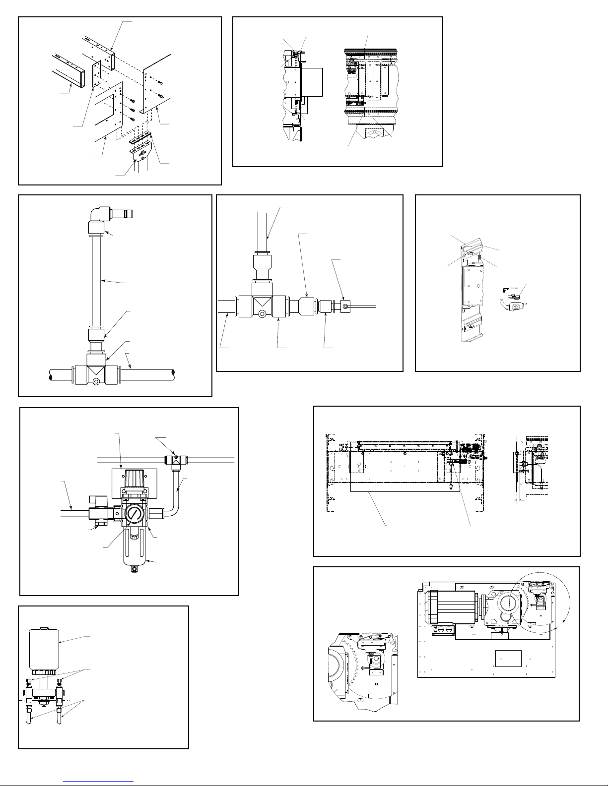
TE
E
BEARING PROFILE
BEARING PROFILE
JOINT
(SECCION DE UNION)
(PERFIL DEL
COJINETE)
(PERFIL DEL
COJINETE)
FIGURA 40A
BED SPACER
(ESPACIADOR
DE CAMA)
SPLICE
(EMPALME)
SIDE CHANNEL
(CANAL LATERAL)
PIVOT PLATE
(PLACA PIVOTE)
BED SPACER
(ESPACIADOR DE CAMA)
SIDE CHANNEL
(CANAL LATERAL)
VIBRATION PAD
(PROTECTORES
DE VIBRACION)
FIGURA 40B
CHAIN COVER
(CUBIERTA DE
CADENA )
UHMW WEARSTRIP
(TIRA DE DESGASTE
UHMW)
UHMW
WEARSTRIP
(TIRA DE DESGASTE
UHMW)
CHAIN GUIDES
OVERLAP JOINT
(JUNTA DE RECUBRIMIENTO
DE GUÍAS DE CADENA)
CHAIN GUIDES OVERLAP
(JUNTA DE RECUBRIMIENTO
DE GUÍAS DE CADENA)
SECTION JOINT
INTERMEDIATE
SWITCHES
(INTERRUPTORES
INTERMEDIOS)
FIGURA 40F
MOUNTING BRACKET
(FASTEN TO
CONVEYOR CHANNEL)
(PLACA DE MONTAJE
[SUJETAR AL CANAL
DEL TRANSPORTADOR])
MAIN AIR
SUPPLY
LINE
(SUMINISTRO
PRINCIPAL
DE AIRE)
LOCK-OUT VALVE
(VÁLVULA DE BLOQUEO)
(MEDIDOR)
GAUGE
FIGURA 40C
3/8" FEMALE TO 3/8" MALE
QUICK CONNECT FITTING
PLUG INTO VALVE
(HEMBRA DE 3/8" A MACHO DE 3/8"
DE RAPIDA CONEXION A VALVULA)
3/8" LINE
(LINEA DE 3/8")
1/2" to 3/8" REDUCER
(REDUCTOR DE 1/2" A 3/8")
1/2" TEE
(TE DE 1/2")
1/2" MAIN LINE
(LINEA PRINCIPAL DE 1/2")
1/2" UNION TEE
(UNION TE DE 1/2")
AIR SUPPLY TO
AIR VALVES
(SUMINISTRO D
AIRE A LAS
VALVULAS)
FILTER/REGULATOR
(REGULADOR/FILTRO)
BOWL GUARD
(TAZON PROTECT OR)
FIGURA 40D
MAIN AIR
(LINEA PRINCIPAL
DE AIRE)
LINE TO VALVE
(LINEA A LA VALVULA)
1/2" TO 3/8" REDUCER
(REDUCTOR DE 1/2" A 3/8")
1/2" TEE
(TE DE 1/2")
FIGURA 40H
FIGURA 40I
PRESSURE SWITCH
PRE SET AT 48 PSI
(INTERRUPTOR DE
PRESION AJUSTADO
A 48 PSI)
3/8" TO 1/4" REDUCER
(REDUCTOR DE 3/8" A 1/4")
SWITCH SENSOR
(INTERRUPTOR
DEL SENSOR)
FIGURA 40E
CHAIN COVER
(CUBIERTA DE
CADENA)
CHAIN GUIDE
MOUNTING ANGLE
(SECCION DE UNION)
PROXIMITY SWTICH
(INTERRUPTOR DEL
PROXIMIDAD)
CHAIN GUIDE WEARSTRIP
(TIRA DE DESGASTE DE
GUÍA DE CADENA)
BEARING PROFILE
(PERFIL DEL COJINETE)
FORCE BEARING
PROFILE UNDER
WEARSTRIP
(FUERCE EL PERFIL DEL
COJINETE DEBAJO DE
LA TIRA DE DESGASTE)
1/8"-3/16" FROM PROX
FACE TO METAL PLA
(1/8" - 3/16" DESDE LA
SUPERFICIE DE
PROXIMIDAD HASTA
LA PLACA METÁLICA)
FIGURA 40G
OIL CUP
(RECIPIENTE
DE ACEITE)
ADJUSTMENT SCREWS
(TORNILLOS DE AJUSTE)
OIL LINES TO BRUSHES
(LINEAS DE ACEITE
PARA LAS BROCHAS)
TRANSITION ASSEMBLY
DETAIL
(DETALLE DE CONJUNTO
DE TRANSICIÓN)
L
40
Page 41
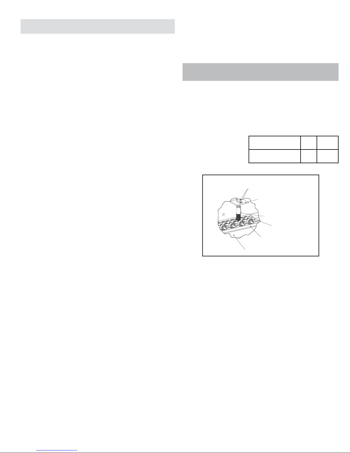
• Equipo Eléctrico
¡PRECAUCIÓN! Debido a la cantidad de partes en movimiento del transportador,
todo el personal en el área debe ser notificado cuando el transportador sea puesto
en marcha.
Código Eléctrico: Todos los controles del motor y las conexiones deben ajustarse
al Código Nacional de Electricidad, (Artículo 670 u otros artículos aplicables)
como fue publicado por la Asociación Nacional de Protección Contra Incendios, y
aprobado por el Instituto Nacional Americano de Normalización.
ESTACIONES DE CONTROL
A) Las estaciones de control deberán estar ordenadas y ubicadas en lugares
donde el funcionamiento del equipo sea visible y deberán estar claramente
marcadas o señalizadas para indicar la función controlada.
B) Un transportador que pueda causar lesiones cuando sea puesto en marcha,
no deberá ponerse en funcionamiento hasta que los trabajadores en el área sean
alertados por una señal o por una persona designada.
Cuando un transportador pueda causar lesiones al momento de
arranque y es controlado automáticamente, o es controlado desde una ubicación
lejana; se deberá proporcionar un dispositivo sonoro el cual pueda ser escuchado
claramente en todos los puntos a lo largo del transportador donde el personal
pueda estar presente. El dispositivo de advertencia deberá ser activado por el
dispositivo de arranque del transportador y deberá continuar sonando por un
determinado periodo de tiempo previo al arranque del transportador. Si es más
efectivo y de acuerdo a las circunstancias se puede utilizar una luz intermitente o
una advertencia visual similar, en lugar del dispositivo sonoro.
Cuando el funcionamiento del sistema pueda ser seriamente obstruido
o adversamente afectado por el tiempo de retardo requerido, o cuando el intento de
advertencia pueda ser mal interpretado (ej., un área de trabajo con diversas líneas
de transportadores y los dispositivos de advertencia relacionados), advertencias
claras, concisas y legibles deben ser proporcionadas. Las advertencias deben
indicar que los transportadores y los equipos relacionados pueden ser puestos
en marcha en cualquier momento, que existe un peligro y que el personal debe
mantenerse alejado. Estas advertencias deben ser proporcionadas a lo largo del
transportador en áreas que no sean protegidas por la posición o la ubicación.
C) Los transportadores controlados automáticamente, desde estaciones
lejanas y los transportadores donde las estaciones de funcionamiento no estén
controladas por una persona o estén más allá del alcance de la voz y del contacto
visual de las áreas de conducción, áreas de carga, puntos de transferencia y otros
sitios potencialmente peligrosos localizados en la trayectoria del transportador
que no tenga protección por posición, ubicación o guardas, deberán ser
equipados con interruptores de parada de emergencia, cordones de parada
de emergencia, interruptores de límite o dispositivos similares para paradas de
emergencia.
Todos estos dispositivos de parada de emergencia deberán
ser fácilmente identificables en las cercanías inmediatas a estos puntos
potencialmente peligrosos, a no ser que estén protegidos dada su ubicación,
posición o protegidos con guardas. No se requieren los dispositivos de parada
de emergencia donde el diseño, el funcionamiento y la operación de tales
transportadores no represente un claro peligro para el personal.
El dispositivo de parada de emergencia debe actuar directamente
en el control del transportador concerniente y no debe depender de la parada
de cualquier otro equipo. Los dispositivos de parada de emergencia deben ser
instalados de tal forma que no puedan ser anulados desde otras localidades.
D) Los controles, los actuadores inactivos o no usados y los cables, deberán ser
removidos de las estaciones de control y de los tableros de mando, junto con
los diagramas, indicadores, etiquetas de control y otros materiales obsoletos, los
cuales pueden confundir al operador.
DISPOSITIVOS DE SEGURIDAD
A) Todos los dispositivos de seguridad, incluyendo la conexión de dispositivos
eléctricos, deben estar dispuestos para operar en una manera de “Fallo Seguro”; es decir, si se presenta una pérdida de corriente o una falla en el mismo
dispositivo, esto no debe representar ningún peligro.
B) Paros de Emergencia y Reinicio. Los controles del transportador deberán estar
dispuestos de tal manera que, en caso de un paro de emergencia se requiera
un inicio o arranque manual en la ubicación donde el paro de emergencia se
presentó para poder reanudar la operación del transportador o transportadores
y equipo asociado.
C) Antes de volver a poner en marcha un transportador que haya sido detenido
por una emergencia, debe revisarse y determinar la causa del paro. El dispositivo
de arranque deberá ser bloqueado antes de intentar corregir o remover la causa
que originó el paro, a no ser que la operación del transportador sea necesaria
para determinar la causa o para solucionar el problema.
Refiérase a: ANS I Z244.1, “American National Standard for Personnel Protection”
- Lockout/Tagout of Energy Sources - Minimum Safety Requirements and OSHA
Standard Number 29 CFR 1910.147 “The Control of Hazardous Energy (Lockout/
Tagout).”
OPERACION
• Arranque del Transportador
Antes de poner en marcha el transportador, revise si hay objetos ajenos que
puedan haber sido dejados dentro del transportador durante la instalación. Estos
objetos pueden causar serios daños en el arranque.
Después de poner en marcha el transportador y esté operando, verifique los
motores, reductores y partes en movimiento para estar seguro de que están
trabajando libremente.
¡PRECAUCION! Debido a la cantidad de partes en movimiento del transportador,
todo el personal en el área del transportador necesita ser advertido de que este
está a punto de ponerse en marcha.
MANTENIMIENTO
• Lubricación
RODAMIENTOS
A) NO GREASE FITTING—Prelubricados—No se necesita lubricación.
B) WITH GREASE FITTING—Lubricar cada 10 a 12 semanas con aceite a base
de litio apropiado para los balines de los rodamientos
LUBRICANTE DE CADENA RECOMENDADO
Se recomienda un aceite sintético
o de petróleo sin detergente
limpio de buena calidad.
Consulte el cuadro para conocer
la viscosidad adecuada.
REDUCTORES
Refiérase a las recomendaciones del fabricante.
OILER BRUSH ADJUSTMENT
(AJUSTE DEL CEPILLO DEL ENGRASADOR)
AJUSTE DEL CEPILLO DEL ENGRASADOR
Es muy importante que el cepillo del engrasador tenga contacto con la cadena para
obtener una lubricación adecuada y una mayor vida útil de la cadena. Para realizar
esto, use las tuercas de ajuste y las escuadras de soporte.
• Controlando el ProSort
Un buen software es esencial para la operación correcta del ProSort. Con los
controles correctos, el clasificador proveerá precisión, eficiencia y confianza por
muchos años. Por el contrario controles inadecuados pueden ser la causa de un
desempeño inadecuado del sorter y son la causa principal de colapsos y fallas
mecánicas del mismo.
Cada sistema de clasificación es diferente, por lo tanto cada sistema tiene
controles únicos y adecuados para ese sistema. Estos controles son usualmente
proporcionados por el distribuidor Hytrol, el usuario o por un tercero.
Hytrol ha incorporado en el clasificador algunos controles necesarios para
operar los interruptores desviadores, eliminando la necesidad de controlarlos
externamente. Otros componentes del control eléctrico también se proporcion con
el clasificador para permitir que controles exteriores detecten detalles críticos y
para una interface entre los controles eléctricos y el sorter mecánico. Aún asi, otros
componentes de control deben ser proporcionados por el proveedor del paquete
especifico de control para asegurar una operación de clasificación adecuada.
Esta sección del manual incluye la siguiente información para el proveedor de los
controles:
1. Una descripción de los componentes del control proporcionado del interruptor
desviador y sus funciones.
2. Una descripción de los otros componentes de control provistos con el sorter y
su función principal.
3. Una descripción de los componentes de control que no son incluídos con el
sorter y que deben ser proporcionados por el proveedor de los controles.
4. Algunas recomendaciones en que y que no hace, con controles para ayudarlo
en el diseño e instalación del paquete de control.
Por favor lea esta sección completamente y compártala con el proveedor de los
controles.
T emperatura Ambiente
Grados F or Grados C
20-40 -07-07
40-100 04-38
ADJUSTING NUTS
(TUERCAS DE AJUSTE)
OILER SUPPORT BRACKET
(ENGRASADOR DE ESCUADRA
DE SOPORTE)
OILER BRUSH
(CEPILLO DEL ENGRASADOR)
CHAIN
(CADENA)
WEARSTRIP
(TIRA DE DESGASTE)
TAIL SECTION
(SECCIÓN DE RETORNO)
SAE ISO
203046 or 68
100
41
Page 42
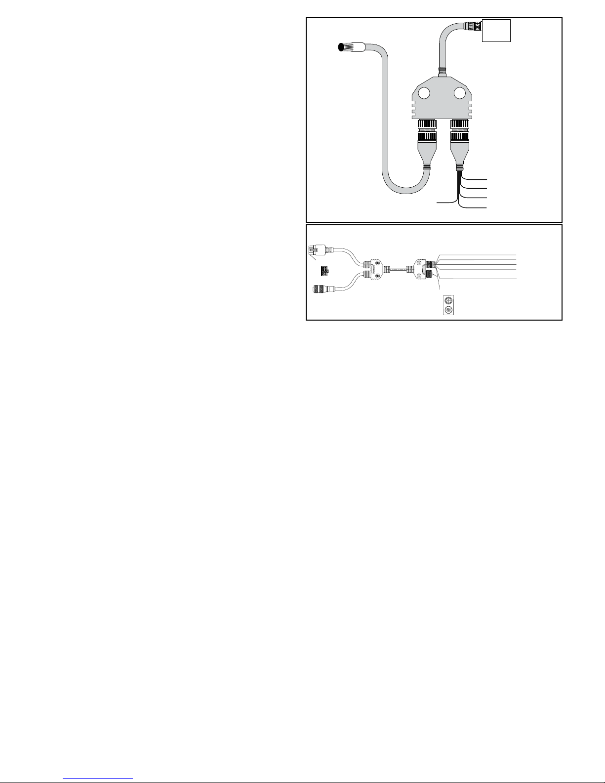
Un control apropiado del interruptor desviador es fundamental para lograr una
CONTROL DEL INTERRUPTOR DESVIADOR
operación del sorter segura y confiable. No controlar correctamente el interruptor
desviador es una de las causas más comunes de daños en el mismo y de
“colapsos” durante la operación.
El interruptor desviador funciona similarmente a un interruptor en la vía del tren,
permitiendo que los bloques desviadores viajen tanto en dirección rectilínea por la
vía “sin-desviación”, o diagonalmente a través del sorter por la “vía de desviación”
empujando el producto fuera del mismo. Cuando el interruptor está en posición
“standard”, los bloques desviadores viajan en dirección rectilínea. Cuando el
interruptor está en posición “desviar”, hace que los bloques viajen por la vía de
desviación.
La transición del interruptor entre las posiciones “standard” y “desviar” debe ser
perfectamente cronometrada para evitar colapsos durante la clasificación. De la
misma forma que un interruptor de cambio de vía de tren no puede ser operado
en forma segura mientras el tren está pasando, el desviador no puede ser
operado seguramente cuando un bloque interruptor pasa a través del mismo. Si
el mecanismo del interruptor no está programado para actuar solamente cuando
ningún bloque desviador está presente en el interruptor, el pin guia del bloque
puede chocar con el punto inferior del bloque del interruptor resultando en daños
al interruptor y potencialmente en paradas costosas.
El ProSort tiene dos componentes de control en cada desviador que trabajan en
conjunto para cronometrar con precisión el movimiento u operación, eliminando
la necesidad de que el proveedor del control lo haga. Estos componentes son el
“smart prox” y la válvula solenoide de aire de alta velocidad.
“SMART PROX”
El “smart prox” es un sensor de proximidad inductivo diseñado exclusivamente
para Hytrol, el cual tiene la “inteligencia” para controlar la regulación del tiempo del
interruptor. El prox se conecta al cable Y. Ver Figura 42A:
Café—Potencia de entrada al prox de +24VDC.
FIGURA 42A
SMART PROX
SMART
PROX
SERVO MOTOR CONNECTOR
(CONECTOR DE SERVOMOTOR)
END VIEW
(VISTA POSTERIOR)
HOMING PROX
(SENSOR DE PROXIMIDAD
DE AUTODIRECCIÓN)
SMART PROX
AND VALVE
CONNECTION
(SMART PROX Y
CONEXION A
VALVULA SOLO)
1 2
(NOT USED/SIN USAR)
SMART PROX CORD SET
WHITE/BLANCO
(JUEGO DE CABLES
SMART PROX)
SMART PROX
TOP VIEW
SOLENOID
VALVE
(VALVULA
SOLENOIDE)
SMART PROX
TO SOLENOID
"Y" CONNECTOR
032.21124
(SMART PROX Y
A SOLENOIDE
CABLE Y)
SMART PROX
CORD SET
(JUEGO DE CABLES
SMART PROX)
BROWN/CAFÉ
+24 VOLTS DC/+24 V CC
BLUE/AZUL
DC COMMON/CC COMÚN
GRAY/GRIS
SMART PROX ENABLE/
HABILITAR SMART PROX
BLACK/NEGRO
SMART PROX STATE/
ESTADO DE SMART PROX
FIGURA 42B
BROWN/CAFÉ +24 VOLTS DC/+24 V CC
WHITE/BLANCO PROX OUTPUT/SALIDA DEL SENSOR DE PROXIMIDAD
BLUE/AZUL +24 VOLTS DC/+24 V CC
BLACK/NEGRO DIVERT ENABLE/HABILITAR DESVIACIÓN
GRAY/GRIS ALL SYSTEMS GO SIGNAL/
SEÑAL DE TODOS LOS SISTEMAS LISTOS
(VISTA SUPERIOR)
Azul—Conductor tierra (-) para el prox.
Gris—Conductor para el prox que habilita el interruptor. Cuando una señal de
24VDC (alta) es dada al conductor por controles del sistema, el prox espera
que se detecte el siguiente bloque desviador y provee una salida de 24VDC a
la válvula solenoide de aire a través del conductor blanco. La válvula solenoide
se encarga en este momento de hacer que el interruptor desviador cambie a la
posición “desviar”. Todos los bloques viajando a lo largo del interruptor seguirán
la vía desviadora mientras la señal habilitadora esté activa (en alto). Cuando la
señal desviadora es removida (en bajo) el prox espera detectar el próximo bloque
desviador, cerrando la salida que va a la válvula solenoide. El interruptor desviador
regresará a la posición “standard” y los bloques siguientes seguirán la vía recta
“sin-desviación”. La señal habilitadora a este conductor es la única señal que los
controles del sistema deben proporcionar al control del interruptor desviador.
Cable Y
El cable Y se usa para conectar el “smart prox”, la válvula solenoide de aire y los
controles del sistema. El set macho de cables que se origina en el “smart prox”
se conecta al terminal #1 del cable Y. La “cola” del cable Y se conecta al enchufe
macho en la váluva solenoide de aire del interruptor desviador. El set hembra de
cables se conecta al terminal #2 del cable Y. Los conductores del set del terminal
#2 tienen las siguientes funciones. (Fig 42A) NOTA: El cable Y no se usa en
secciones desviadoras dobles.
Negro—Conductor de salida estándar del prox. Este conductor provee una señal
de 24VDC (alto) cada vez que el prox detecte un bloque desviador. Esta es una
salida opcional y debe ser usada a discreción del proveedor de controles.
REQUISITOS ELÉCTRICOS
• Energía de CC proporcionada por el cliente: 300 mA a 24 V CC
• Todas las entradas a Smart Prox son de profundización.
• Todas las salidas desde Smart Prox son surtidoras.
VALVULA SOLENOIDE DE AIRE DE ALTA VELOCIDAD
La válvula solenoide de aire se usa para recibir la señal de salida del smart prox
y proporciona aire al extremo apropiado del cilindro del interruptor desviador para
mover y mantener el interruptor ya sea en posición “standard” o en “desviar”.
La válvula está especialmente diseñada para una operación de alta velocidad
necesaria para un tiempo exacto de desviación. Las dos entradas del solenoide
son no polarizadas, permitiendo que cualquier conductor sea usado como entrada
o tierra para la válvula. El solenoide requiere 24VDC, y 6W para operar. La válvula
es controlada directamente por el prox. El control directo de esta válvula por el
paquete de control es no es recomendado.
Otros Componentes de Control Suministrados con el Transportador
CONTROLADOR MOTRIZ DE FRECUENCIA VARIABLE
La unidad motriz de frecuencia variable (VFD) es un controlador de motor que
tiene dos funciones:
1. Proporciona una aceleración suave del motor, permitiendo que el sorter acelere
suavemente hasta su máxima velocidad. Esto protege los componentes del sorter
de un esfuerzo en caso de un arranque repentino.
2. Permite que la velocidad del sorter se ajuste hasta igualar los requerimientos del
sistema. También permite que el sorter se opere lentamente durante la instalación
y cuando ciertos componentes mecánicos sean revisados.
3. Permite que el sorter se opere a baja velocidad en baja temporada, reduciendo
así el consumo de energia, el ruido y el desgaste.
Refiérase al manual de instalación del VFD, proporcionado con el sorter para
conexiones e instrucciones de ajuste.
INTERRUPTOR DE PRESION DE AIRE
El interruptor es usado para detectar baja presión de aire (Fig. 40D). La operación
del sorter con presión de aire menor que 50 PSI puede causar cambios irregulares
y daño potencial al interruptor. Si la presión de aire se encuentra por debajo de
este nivel, el sorter debe apagarse hasta que la causa de la disminución de presión
sea encontrada y remediada.
El interruptor de presión provee una salida de tipo-contacto, la cual se cierra
con presiones de o mayores que a 48 PSI y se abre con presiones menores. El
proveedor de los controles deberá usar este interruptor para monitorear la presión
del aire en el sorter y deberá apagar el sorter si una salida abierta (baja) es
detectada en el interruptor de presión.
Refiérase al manual de instalación del interruptor de presión, proporcionado con el
sorter, para instrucciones de como debe ser conectado.
INTERRUPTORES DE PROXIMIDAD DE SEGURIDAD
Hay dispositivos de seguridad colocados en varios lugares del sorter para indicar
cuando un bloque desviador este fuera de lugar, cuando hay una obstrucción
en el sorter, o cuando algo haya ocurrido que pudiera causar daño el sorter o
peligro al personal. Estos interruptores de seguridad usan interruptores normales
de proximidad inductivos como el interface eléctrico a los controles del sistema.
Hay dos tipos de interruptores de seguridad en el sorter:
1. Interruptores de seguridad de bloque son mecanismos dentro del clasificador
que detectan si un bloque está desalineado. También sirven para detectar objetos
ajenos que hayan caido en los tubos extendidos y dentro del clasificador. Están
hechos para detectar problemas en ambas secciones del clasificador (ya sea la
superior o de retorno).
Hay un interruptor localizado en la zona de carga y de descarga del clasificador.
Hay interruptores adicionales cada 30 pies del clasificador. Por ejemplo, un sorter
de 30 pies de largo tendrá 3 interruptores; uno de 80 pies tendrá 4 interruptores y
asi en adelante. Estos interruptores adicionales están espaciados igualmente a lo
42
Page 43
largo de toda la longitud del sorter.
2. El interruptor de seguridad de transición se utiliza para detectar cuando el
conjunto de transición en el extremo de descarga del clasificador se empuja
fuera de su posición, si un soporte de desviación suelto o un objeto extraño hace
contacto con ellos.
El estado normal de salida de los interruptores de proximidad es “on” (alto). Si un
interruptor detecta un problema, la señal se cambia a “off” (bajo). El control del
sistema debe estar configurado para ir a una condición de “paro de emergencia”
y apagar el sorter y el equipo relacionado cuando sea corrija un problema. No se
debe poner en marcha hasta que el problema sea detectado y el interruptor de
proximidad que detectó el problema se encuentre de nuevo en “on.”
Refiérase al manual de instalación del interruptor de proximidad para instrucciones
de como conectarse, proporcionado con el sorter.
FOTO CELDA TENSION CATENARIA
La foto celda controla la cantidad de pandeo de la cadena que ocurre en el área
de la catenaria. La foto celda es un retro-reflector operando con señal de luz,
colocado en la catenaria; así que si los tubos extendidos bajan más que el nivel
marcado, el haz de la foto celda se bloquea.
Los controles del sistema se deben configurar para detener el clasificador cuando
el haz de células fotoeléctricas se bloquee continuamente (la salida de células
fotoeléctricas está “apagada” o “baja”) y proporcionar una indicación al operador
del clasificador de que las cadenas se deben recoger o acortar antes de seguir
operando el clasificador.
Refiérase al manual de instalación de la foto celda, adjunto con el sorter, para
instrucciones de como conectarlo.
CODIFICADOR
El codificador viene incluido con el sorter para dar una señal que sirve para rastrear
el producto. El codificador da una señal de pulsación de onda-cuadrada de diez
transiciones de baja-a-alta y de alta-a-baja por revolución del eje alimentador del
sorter, para una resolución de veinte pulsaciones por revolución. Esto equivale a
una pulsación (sea 10 “altas” y 10 “bajas”) por cada 1,301 pulgadas de trayecto
del sorter.
El codificador requiere 24VDC de potencia y provee una salida de pulsación de
24VDC.
Refiérase al manual de instalación del codificador, provisto con el sorter, para
instrucciones de como conectar.
SOLENOIDE DE LUBRICADOR DE CADENA
El lubricador es utilizado para proporcionar una lubricación automática de
las cadenas durante la operación del sorter. Cuando la válvula solenoide del
lubricador recibe energía, el aceite de la reserva fluye por gravedad a las válvulas
de medición y luego a las brochas localizadas sobre las cadenas de retorno del
sorter.
Los controles del sistema se deben configurar para activar el solenoide del
engrasador de la cadena durante una duración igual a un giro completo de las
cadenas transportadoras, aproximadamente cada cuarenta horas de operación.
La cantidad de aceite aplicada es controlada por los torni-llos de medición (Vea la
sección “Montaje” en este manual).
El lubricador de cadena requiere una pontencia de 24VDC.
DETECCION DE RODAMIENTO PERDIDO
El bloque de rodamiento faltante se usa para identificar un rodamiento faltante
en un zapato desviador. Un zapato desviador que no tiene un rodamiento en
el fondo puede provocar daños al clasificador. El bloque de rodamiento faltante
usa dos sensores de proximidad, que se localizan en la sección de retorno del
clasificador, para identificar la presencia de un rodamiento sobre el zapato. Si
un sensor de proximidad detecta la presencia de un rodamiento pero la del otro
no, se borrará el indicador para señalar la detección de un rodamiento faltante.
El sensor de proximidad del cojinete faltante se encuentra en la parte inferior de
la sección de desviación de descarga. El detector de cojinete faltante tiene una
señal normalmente alta que generará 24VDC, siempre y cuando no se detecten
pasadores o cojinetes faltantes. Si se detecta un pasador o cojinete faltante, la
señal bajará su potencia y el PLC debe detener el clasificador. Antes de reiniciar
el clasificador, el PLC debe impulsar 24VDC hacia la entrada RESET ERROR
(Error de restablecimiento) en el detector de cojinete faltante. Al realizar esto se
restablecerá el detector de tal manera que la salida se vuelva a encender.
El detector de cojinete faltante también posee una función opcional para probar el
funcionamiento adecuado de los sensores de proximidad que utiliza el detector.
El detector tiene una segunda salida (BROKEN PROX ERROR [Error de sensor
de proximidad dañado]) que normalmente está en nivel alto (24VDC) mientras los
sensores funcionan de manera normal. Esta salida se activa mediante una entrada
de clasificador en funcionamiento (SORTER RUNNING INPUT) hacia el detector.
Si se proporciona una señal (24VDC) hacia dicha entrada mientras el controlador
de velocidad variable (VFD, por sus siglas en inglés) del clasificador está habilitado,
activará la prueba para detectar un sensor de proximidad con funcionamiento
defectuoso. La entrada de clasificador en funcionamiento (SORTER RUNNING
INPUT) debe permanecer energizada para que la salida de error de sensor
de proximidad dañado (BROKEN PROX ERROR OUTPUT) se energice así
como también para continuar las pruebas de los sensores de proximidad. Si se
detecta un sensor de proximidad con funcionamiento defectuoso, los sensores de
proximidad y todas las conexiones hacia los sensores se deben inspeccionar y
reparar o reemplazar. El error de sensor de proximidad dañado (BROKEN PROX
ERROR) se debe restablecer de la misma manera que el error de cojinete faltante.
La energía para operar el detector de cojinete faltante, los sensores de proximidad
y las señales que vuelven hacia el PLC proviene totalmente de una fuente de
24VDC proporcionada por el cliente. La energía de 24VDC, 200 mA necesaria
se debe proporcionar por medio del conector M12 etiquetado “INPUT” (Entrada).
Componentes de Control no Suministrados con el Transportador
Además de los componentes de control suministrados con el ProSort, hay varios
componentes que deben ser suministrados por el proveedor de los controles del
sistema. Hytrol recomienda el uso de los siguientes componentes para prevenir
daños en el sorter debido a obstrucción de productos u otros problemas.
REGULADOR DE SOBRECARGAS DEL MOTOR
El regulador provee protección contra daños apagando el motor cuando se detecta
un aumento repentino de corriente. Al ajustar ligeramente el límite de sobrecarga
por encima de la potencia requerida para operar el sorter, cualquier extra carga
como una obstrucción o un mal funcionaniento, hará que el sorter se detenga,
posiblemente antes de causar un daño significativo al equipo.
El regulador debe ser instalado en el panel de control para medir la potencia
correcta del motor.
FOTO CELDA
Las foto celdas son componentes comunes en los controles del sistema. Hytrol
recomienda que las foto celdas sean instaladas en los siguientes lugares para que
realicen las funciones descritas. Estas son algunas foto celdas entre otras que se
necesiten en el sistema.
Foto celda de Inducción—Una foto celda colocada en el punto alimentador del
sorter. Esta es usada para realizar las siguientes funciones:
1. Avisar a los controles del sistema que un paquete particular ha entrado en
el sorter. Desde este punto en adelante, el paquete debe ser rastreado usando
las pulsaciones del codificador para determinar cuando alcanza el punto de
desviación asignado.
2. Medir la longitud del paquete para que los controles del sistema puedan asignar
el número correcto de bloques desviadores necesarios para desviarlo. Nota: El
número de bloques se asigna de acuerdo a la longitud total del paquete más uno
extra para el extremo del mismo.
3. Revisar el espacio apropriado entre los paquetes para una clasificación segura.
Es importante revisar acá el espacio correcto aunque ya haya sido establecido
antes de llegar a este punto, para asegurar que los paquetes estén espaciados
correctamente. Intentar clasificar los paquetes con poco espacio entre ellos puede
causar obstrucciones. Nota: El mínimo espacio necesario para la clasificación de
un paquete está en función del ancho del mismo. Las siguientes tablas deben
considearse al asignar el gap apropiado.
0" < W ² 6" Brecha mínima = 6"
6" < W ² 18" Brecha mínima = 9"
18" < W ² 30" Brecha mínima = 12"
* W = Ancho del Paquete
Minimum gap = Espacio mínimo
Nota: Cuando se clasifica hacia
ambos lados, el espacio mínimo
en la tabla debe incrementarse
en 3 pulgadas.
Foto celda de Confirmación/Obstrucción—Las foto celda se coloca en las
espuelas acopladas al sorter lo más cerca posible al mismo. Esta foto celda tiene
dos funciones:
1. Detectar un producto atorado en el punto de salida del sorter. Si un paquete
bloquea esta foto celda por más tiempo de lo que le tomaría a este viajar y pasar la
foto celda normalmente, esto indica que el paquete se encuentra atorado. El sorter
debe ser detenido y la obstrucción removida antes de volver lo a poner en marcha.
2. Confirmación de desviación. Si una señal de desviación es dada para un punto
particular de desviación ningún paquete es detectado por la foto celda asociada,
un error ha ocurrido. El sorter debe ser detenido y el error detectado y corregido
antes de ponerlo en marcha.
Foto celda de Línea Llena—Las foto celdas que son montadas en las líneas
desviadoras del sorter, lo más cerca posible al extremo alimentador de las
mismas, se encargadas de dar una señal a los controles del sistema cuando
una línea particular desviadoras está llena. Los controles harán que los paquetes
asignados a esta línea recirculen hasta que la foto celda deje de indincar que la
línea se encuentra llena.
Las siguientes son recomendaciones para auxiliar en el diseño e instalación de
los controles del sistemas correspondientes al ProSort.
• No instale los cables de control de 24VDC en el mismo punto que los cables
eléctricos puede producir efectos indeseables.
• No use la “salida prox estándar” opcional del smart prox para sustituir el
ProSort 121 (desvía 22°)
ProSort 131 (desvía 30°)
0" < W ² 6" Brecha mínima = 6"
6" < W ² 12" Brecha mínima = 9"
12" < W ² 18" Brecha mínima = 12"
18" < W ² 24" Brecha mínima = 15"
Recomendaciones sobre Controles
43
Page 44
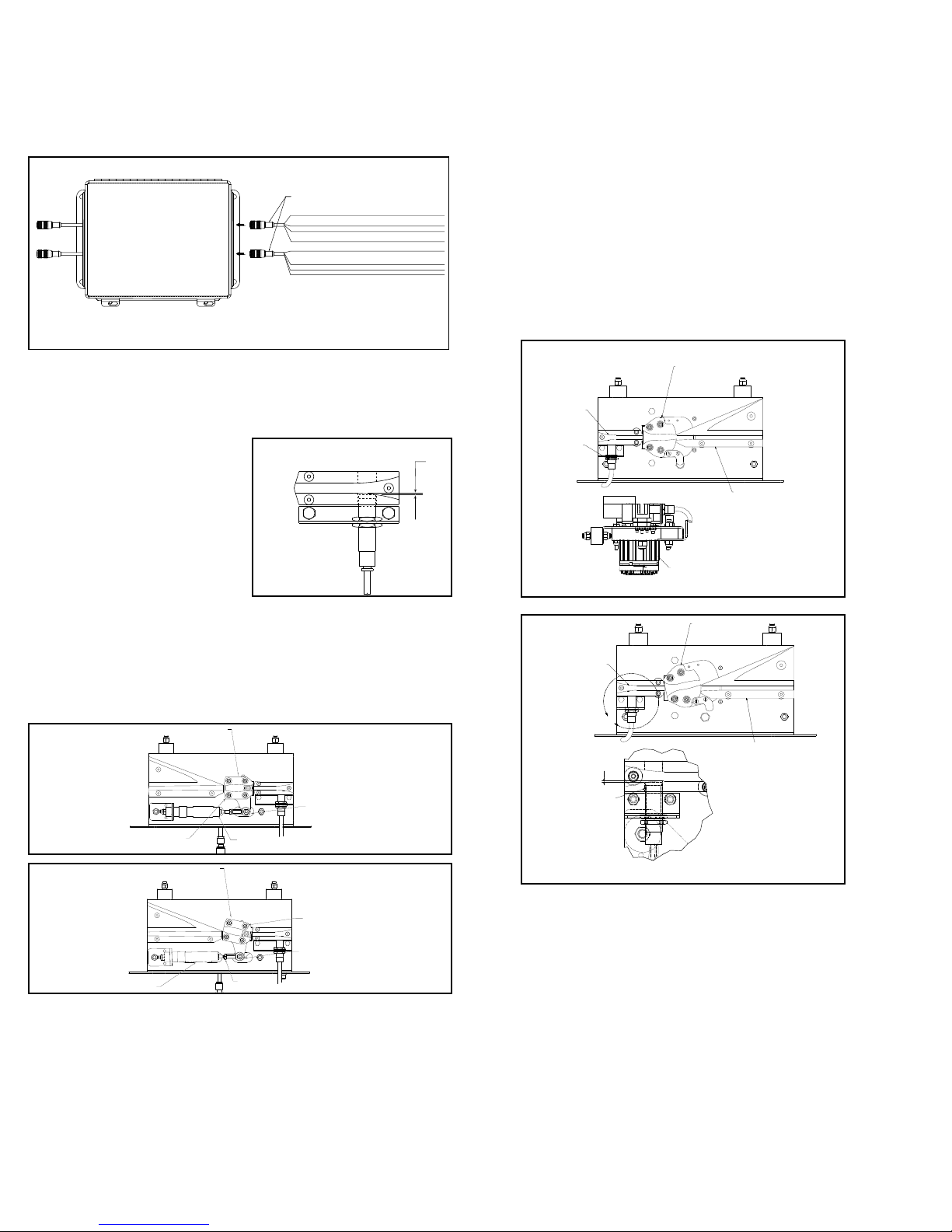
codificador. El espacio de 5 pulgadas entre bloques desviadores no proporciona
(CONTRA TUERCA)
SCALE 1.50 : 1
(ESCALA 1.50: 1)
suficiente resolución al rastrear para clasificar los paquetes correctamente.
• No use el operador manual de la válvula solenoide de aire para operar el
interruptor desviador cuando el sorter está corriendo. Hacerlo desregula el
controlador de tiempo del interruptor lo que puede causar daños en el sorter.
• Trate el disparo de cualquier interruptor de seguridad, sobrecarga del motor o
señal de baja presión del aire como una parada de emergencia. Inspeccione los
interruptores de seguridad y otras partes del sorter para asegurar que todo trabaje
perfectamente antes de poner en marcha el sorter.
FIGURA 44A
TO PROX 1
(HACIA SENSOR DE
PROXIMIDAD 1)
TO PROX 2
(HACIA SENSOR DE
PROXIMIDAD 2)
* BROKEN PROX OUTPUT IS ONLY ACTIVE WHEN SORTER RUN INPUT IS ACTIVE.
(LA SALIDA DE SENSOR DE PROXIMIDAD DAÑADO SOLO SE ACTIVA CUANDO LA
ENTRADA DE FUNCIONAMIENTO DEL CLASIFICADOR ESTÁ ACTIVA.)
OUTPUT
(SALIDA)
(ENTRADA)
941.423003
BROWN/CAFÉ NOT USED
WHITE/BLANCO BROKEN PROX ERROR (24=OK, 0V=ERROR)/
ERROR DE SENSOR DE PROXIMIDAD DAÑADO (24 = CORRECTO, 0 V = ERROR)
BLUE/AZUL COMMON/COMÚN
NEGRO OUPUT (24V=OK, 0V=MISSING BEARING DETECTED)
BLACK/
SALIDA (24 V = CORRECTO, 0 V = COJINETE FALTANTE DETECTADO)
INPUT
BROWN/CAFÉ POWER (+24VDC)/ENERGÍA (+24 V CC)
WHITE/BLANCO SORTER RUNNING INPUT (SORTER UP TO SPEED)
ENTRADA DE CLASIFICADOR EN FUNCIONAMIENTO
(CLASIFICADOR A VELOCIDAD NORMAL)
BLUE/AZUL COMMON/COMÚN
BLACK/NEGRO RESET ERROR INPUT/ENTRADA DE ERROR DE RESTABLECIMIENTO
• Revisión del Interruptor Desviador
Neumático
Después de que todas las secciones del
ProSort han sido alineadas e instaladas,
se deben revisar, los interruptores
desviadores para su correcta operación
como sigue:
1. Antes de que la presión del aire sea
suministrada a la válvula solenoide de aire
del interruptor desviador, manualmente
mueva el interruptor de la posición
“no-desviar” a la “desviar”, revisando que
el movimiento sea suave y libre. Determine
y arregle el problema de algún interruptor
trabado. Para la correcta alineación vea
las Figuras 44C & 44D. Si se necesita ajustar el interruptor, afloje la contra tuerca
de la barra actuadora. Atornille la barra actuadora hacia o fuera de su extremo
para ajustar el interruptor y apriete nuebamente la contratuerca.
2. Accione la presión de aire y verifique que cada interruptor desviador esté o se
mueva a la posición estándard (no-desviar) (Fig. 44C).
3. Revise que el smart prox esté instalado correctamente. El frente del prox no
debe obstruir el camino del pin guía del zapato desviador (Fig. 44B).
SWITCH BLOCK
FIGURA 44C
NON-DIVERT POSITION
(POSICION DESVIADORA)
(INTERRUPTOR DE
BLOQUEO)
SWITCH BLOCK
(INTERRUPTOR DE
BLOQUEO)
FIGURA 43B
AIR CYLINDER EXTENDER
(EXTREMO DEL EJE)
ROD END
(EXTREMO DEL EJE)
1/32"
FIGURA 44D
• Revisión del Interruptor Desviador
Eléctrico
NOTA: Todos los desviadores eléctricos servomotores están asignados a las
unidades asociadas en la fábrica. Conectar los motores a la unidad incorrecta
puede tener un efecto negativo en la operación desviadora y podría provocar daño
físico al clasificador. Conecte siempre las unidades a los motores asignados por
la fábrica para evitar daños.
1. Antes de poner en marcha el clasificador conecte el interruptor del sistema
eléctrico y verifique que los desviadores están en la posición desviadora o inicial.
Para asegurar el funcionamiento adecuado, la función desviadora se probó en la
fábrica. Si los desviadores están en la posición desviadora, Fig. 44E, se pueden
regresar a la posición inicial quitando la señal de habilitación del Smart Prox y
después marcando el Smart Prox para activar la operación de movimiento.
2. Siempre que se enciendan las desviaciones, el desviador se moverá lentamente
hasta que encuentre su posición de inicio.
3. Asegúrese de que la señal “Todos los sistemas listos” esté encendida antes de
hacer funcionar el clasificador.
4. Asegúrese que el Smart Prox está posicionado correctamente. La cara del
sensor de proximidad debe posicionarse justo afuera de la guía del camino de los
zapatos.(Fig. 44F)
FIGURA 44E
SWITCH GUIDE
(GUÍA DEL
INTERRUPTOR)
PROX SWITCH
(INTERRUPTOR
DE PROXIMIDAD)
FIGURA 44F
SWITCH GUIDE
(GUÍA DEL
INTERRUPTOR)
1/32
PROX SWTICH
(INTERRUPTOR
DE PROXIMIDAD)
U
DETAIL U
NON-DIVERT POSITION
(POSICIÓN SIN DESVIACIÓN)
DIVERT BLOCK
(BLOQUE DE DESVIACIÓN)
NON-DIVERT POSITION
(POSICIÓN SIN DESVIACIÓN)
SERVO MOTOR
(SERVOMOTOR)
SWITCH BLOCK
(BLOQUE DEL
INTERRUPTOR)
DIVERT POSITION
(POSICIÓN DE
DESVIACIÓN)
(DETALLE U)
DIVERT BLOCK
(BLOQUE DE
DESVIACIÓN)
DIVERT POSITION
(POSICION DESVIADORA)
ROD END
(EXTREMO DEL EJE)
AIR RETRACTED
JAM NUT
44
Page 45
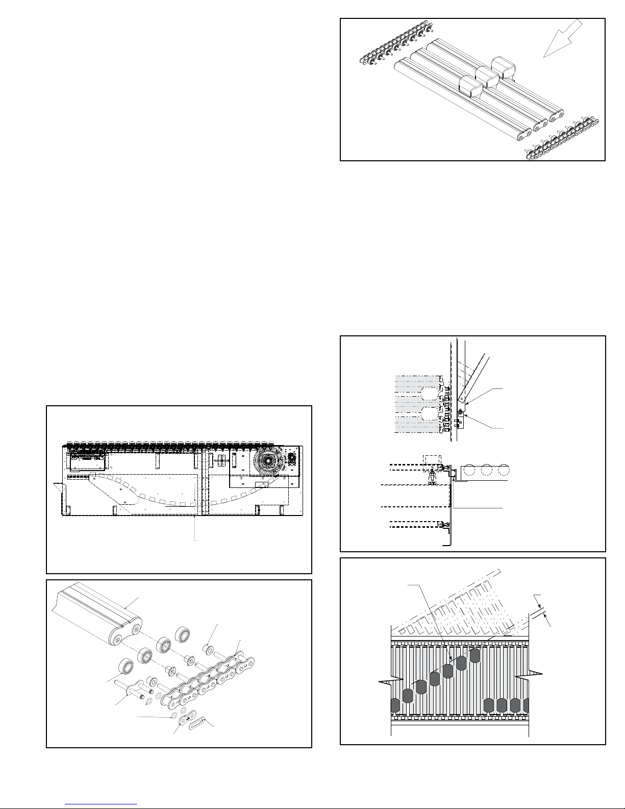
• Instalación de Cadenas
CARRYING CHAIN
Las cadenas son enviadas en carretes marcados, cortadas a la longitud apropiada
de cada ProSort. Los pasos al instalar son los siguientes:
1. Desconecte la fuente de poder del motor para prevenir arranques repentinos.
2. Revise la alineación de las guías de las cadenas utilizando dos piezas cortas de
cadena con los tubos y rodamientos ensamblados a los pines. El ensamble de la
cadena/tubo/zapato debe deslizarse libremente por las guías de cadena a lo largo
de toda la longitud del transportador.
3. Instale las cadenas a ambos lados del transportador con los pines dirigidos
hacia el interior (Fig. 45C). Asegúrese de que los pines de cada cadena estén
directamente opuestos uno al otro. Los cojinetes con casquillo se instalan en
cada pin. Para facilitar la instalación de la cadena, se puede instalar un tubo
aproximadamente cada cuatro pies para que sostega la cadena sobre las guías.
4. Sujete los extremos de ambas cadenas con los enlaces como se muestra
en Fig. 45B. Siga las instrucciones del fabricante para obtener una lubricación
adecuada cuando instale los eslabones de unión.
5. Instale dos tubos dentro de los pines de cadena extendidos en un lado del
transportador. Deslice el zapato desviador sobre los tubos con la parte biselada
hacia la zona de descarga (Fig. 45B). Levante la cadena de la guía de cadena, en
el lado opuesto, para que las cadenas se puedan separar e introduzca los pines de
cadena extendidos en el extremo opuesto de los tubos.
6. Después de que todos los tubos y zapatos desviadores sean instalados, apriete
las cadenas con tornillos tensores en el eje motriz. Asegúrese de que el eje motriz
y el de retorno estén escuadrados. Apriete los tornillos de montaje. Observe la
Fig. 45A para obtener la tensión correcta de las cadenas.
7. Mueva manualmente el ensamble completo de la cadena a lo largo de todo el
transportador para asegurarse de que éste corra libremente y que no haya caido
nada dentro del transportador durante la instalación. También asegurese de que
todos los zapatos desviadores hayan sido instalados en los centros correctos. Si las
cadenas se acortan debe ser en incrementos de tres pulgadas.
8. Conecte nuevamente la fuente de poder del motor.
• Instalando las Guardas en Puntos
FIGURA 45C
W
O
L
F
(FLUJO)
• Ubicando las Espuelas
Las espuelas de salida deben ser montadas correctamente en las secciones
de desviación del ProSort para asegurar la apropriada desviación del producto.
Las siguientes pautas aplican instalación da unas pautas que se pueden
aplicar en espuelas motorizadas y de gravedad.
1. Acople la espuela al sorter atornillando el brazo soporte de la espuela a
las tuercas de montaje de la misma en el canal lateral del sorter (Fig. 45D).
Sopórte las espuelas como se requiera. Apriete los tornillos manualmente.
2. Coloque manualmente 3 o más zapatos en ángulo desviador como se
muestra. Ponga un nivel contra los zapatos para determinar la ubicación la
“línea desviadora”. Verifique que la distancia entre la “línea de desviación” y
la “BR” (distancia entre rieles) de la espuela sea de al menos 1-1/4" como se
muestra (Fig. 45E).
3. Posicione la espuela verticalmente para que los rodillos/ruedapatín estén
nivelados con los tubos en el sorter. Apriete los tornillos de montaje.
4. Ensamble con tornillo conector surtido con la espuela.
Desviadores
Si las guardas laterales se van a instalar en las espuelas y/o en el lado de la
espuela del sorter, debe tenerse cuidado de que las guardas no interfieran en de
ninguna manera con el producto que esta siendo desviado. Las guardas no deben
ser instaladas de manera que presenten en el área de desviación cuando poseen
orillas filosas o puntiagudas.
FIGURA 45A
ALLOW FROM 5” TO 6” AT INSTALLATION
(PERMITA DE 5 A 6 PULGADAS DE ESPACIO
DURANTE LA INSTALACION)
SLAT
(CADENA)
BUSHING
(CADENA)
FIGURA 45B
(CADENA)
FIGURA 45D
FIGURA 45E
DIVERT LINE
(LINEA DESVIADORA)
SPUR PLATE
(PLACA DE LA
ESPUELA)
SPUR ATT ACHMENT
BRACKET
(BRAZO SOPORTE
DE LA ESPUELA)
UNISTRUT
(CANAL)
1-1/4" Minimum
(1-1/4" como mínimo)
BEARING
(CADENA)
CONNECTOR LINK
(CADENA)
O-RINGS
(CADENA)
COVER PLATE
(CADENA)
SPRING CLIP
(CADENA)
45
Page 46
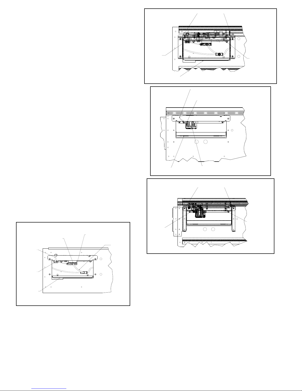
• Procedimiento de Desmontaje del
Interruptor del Desviador Neumático
El ProSort está diseñado de tal manera que el interruptor desviador pueda ser
removido fácilmente para su mantenimiento o reemplazo. Siga los siguientes
pasos para retirar el conjunto de interruptor neumático.
1. Desenchufe el brazo del montaje de la válvula solenoide de aire presionando
la pestaña roja del montaje y luego jalando el brazo.
2. Desconecte el conector del interruptor de proximidad del cable conector en
y. (Fig. 42A)
3. Remueva la cubierta ubicada en el lado del canal del sorter bajo el ensamble
del interruptor desviador, subiendo y girando. (Fig. 46B)
4. Remueva las tres tuercas localizadas en la parte de atrás del canal en el
ensamble del interruptor, a través del agujero situado en el canal lateral. Luego
remueva los dos tornillos de la parte exterior del canal del sorter los cuales
sostienen la parte frontal del canal del ensamble del interruptor hacia arriba.
(Fig. 46B)
5. El lado del canal del ensamble del interruptor puede ser bajado y el
ensamble entero puede ser removido para a través de la abertura en el canal
del sorter.
6. Revise el nuevo ensamble del interruptor de acuerdo a la “Revisión del
Interruptor” en la página 44.
7. Instale el nuevo ensamble del interruptor siguiendo el procedimiento inverso
el con el que se removió el antiguo ensamble.
• Procedimiento de Desarmado del
Interruptor Desviador Eléctrico
El ProSort está diseñado para quitarlo fácilmente del ensamble del interruptor
desviador, para mantenimiento o para reemplazo. Para desarmar el ensamble
del interruptor desviador siga los pasos siguientes.
1. Desconecte toda fuente de alimentación eléctrica que vaya hacia el tablero
conectado al desviador que necesita quitarse. Esto incluye apagar el interruptor
al frente del tablero poniéndolo en la posición OFF, así como desconectar la
fuente de control y alimentación 3-Phase.
2. Después de apagar toda fuente de alimentación eléctrica, espere mínimo 90
segundos para permitir que la energía se disipe por completo a un nivel seguro.
3. Después de los 90 segundos, retire la cubierta que se localiza al costado del
clasicador debajo del ensamble del interruptor desviador levantando y girando
hacia abajo y afuera. Retire el cable M12 de 5 hilos y el cable de alimentación
negro del cable divisor.
4. Meta la mano a través del agujero descubierto en el canal lateral, retire las
dos tuercas en la parte trasera del canal desviador del ensamble. Después
quite los dos tornillos en la parte de afuera del canal clasicador que sostienen
la parte frontal del canal desviador del ensamble (Fig. 46D).
5. La parte frontal del canal desviador del ensamble podría estar reducida y
todo el montaje se puede quitar a través de la entrada en el canal clasicador.
FIGURA 46A
AIR LINE FITTING
(ACCESORIO DE LA
TUBERÍA DE AIRE)
PROX SWITCH
CORD
(CABLE DEL
INTERRUPTOR
DE PROXIMIDAD)
SOLENOID AIR VALVE
(VÁLVULA DE AIRE SOLENOIDE)
AIR LINE
(TUBERÍA
DE AIRE)
FIGURA 46B
REMOVE
LOCK NUTS
(REMUEVA
LAS TUERCAS)
COVER
(CUBIERTA)
FIGURA 46C
COVER
(CUBIERTA)
FIGURA 46D
REMOVE
LOCK NUTS
(REMUEVA
LAS TUERCAS)
REMOVE BOLTS
(REMOVER
LOS TORNILLOS)
REMOVE
LOCK NUTS
(REMUEVA
LAS TUERCAS)
PROX SWITCH CORD
(CABLE DEL INTERRUPTOR DE PROXIMIDAD)
SPLITTER CABLE
(CABLE DIVISOR)
SERVO MOTOR
(SERVOMOTOR)
REMOVE BOLTS
(REMOVER
LOS TORNILLOS)
REMOVE
LOCK NUTS
(REMUEVA
LAS TUERCAS)
Y-CABLE
(CABLE Y)
COVER
(CUBIERTA)
46
Page 47
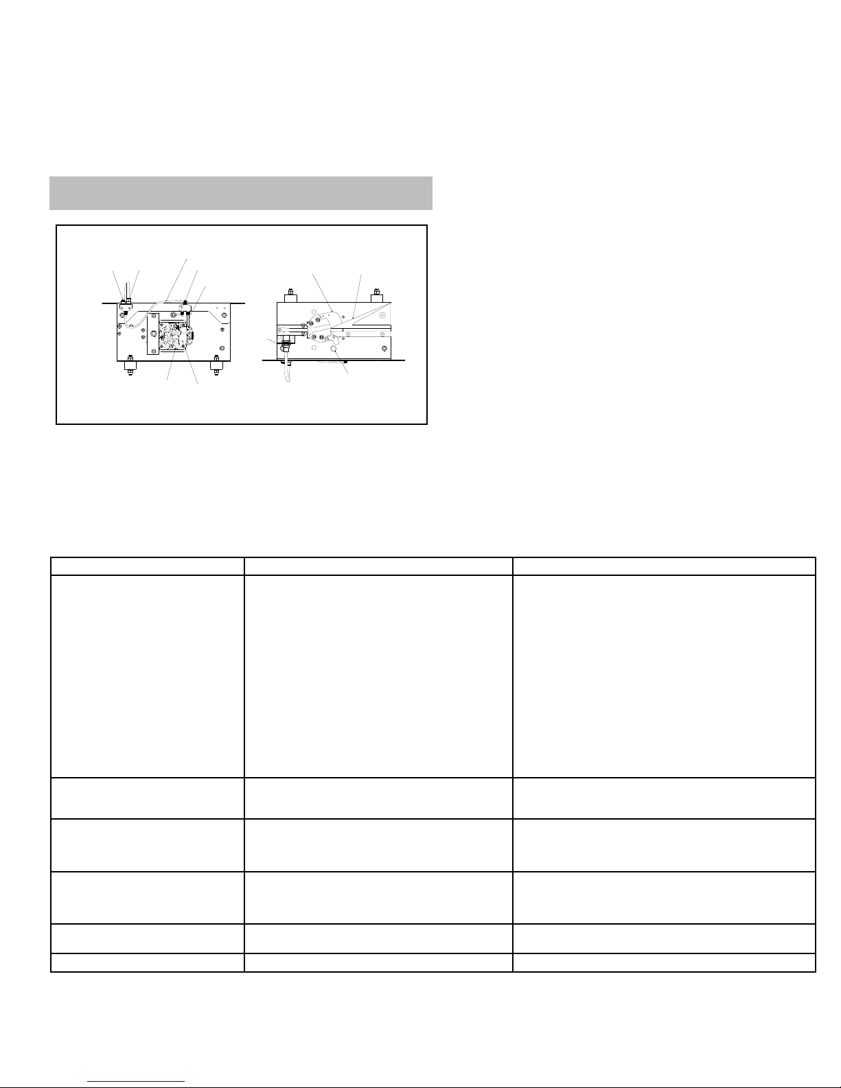
• Procedimiento para Iniciar Eesviador
(BLOQUE DE DESVIACIÓN)
Eléctrico
1. Antes de poner en marcha el clasicador, suministre energía de 24 V CC hacia el
sensor de proximidad de autodirección y el dispositivo Smart prox.
2. Suministre 48 V CC hacia el servomotor (Fig. 47A).
3. El servomotor se somete a un procedimiento de autodirección, donde el bloque del
interruptor gira para encontrar la ubicación de inicio. La realización de este proceso
tarda aproximadamente 10 segundos.
4. Espere la señal de habilitación del interruptor.
5. Ahora el clasicador está listo para funcionar.
¡ADVERTENCIA! Mantenga los dedos alejados del bloque del interruptor durante el
procedimiento de autodirección.
FIGURA 47A
SERVO I/O SPLITTER CABLE
CUSTOMER SUPPLIED
24VDC
(24 V CC PROPORCIONADA
POR EL CLIENTE)
SMART PROX
CONNECTION
(CONEXIÓN DE
SMART PROX)
SERVO MOTOR
(SERVOMOTOR)
BOTTOM VIEW
(VISTA INFERIOR )
(CABLE DIVISOR DE E/S SERVO)
TO HOMING PROX
(HACIA SENSOR DE PROXIMIDAD
DE AUTODIRECCIÓN)
I/O TO SERVO MOTOR
(E/S HACIA SERVOMOTOR)
SMART PROX
HYTROL SUPPLIED
48VDC
(48 V CC PROPORCIONADA
POR HYTROL)
SWITCH BLOCK
(BLOQUE DEL
INTERRUPTOR )
HOMING PROX
(SENSOR DE PROXIMIDAD
DE AUTODIRECCIÓN)
TOP VIEW
(VISTA SUPERIOR)
DIVERT BLOCK
• Resolviendo Problemas
La siguiente tabla muestra una lista de posibles problemas que pueden ocurrir durante la operación del ProSort.
RESOLVIENDO PROBLEMAS DE TRANSMISION
PROBLEMA CAUSA SOLUCION
1) Sensor de obstrucción bloqueado.
2) El interruptor interno de seguridad se disparó.
3) Los rodillos de transición están fuera de su posición.
4) El interruptor de proximidad del interruptor de
seguridad interna o los rodillos de transición están mal
El transportador no arranca o se detiene
automáticamente durante la operación.
ajustados o defectuosos.
5) Baja presión de aire.
a) Regulador ajustado muy bajo.
b) Línea de aire obstruida o cortada.
c) Filtro de aire tapado.
d) Problema en el compresor.
6) Circuitos eléctricos.
7) La velocidad variable de la unidad motriz está
desajustada o defectuosa.
8) La unidad motriz está defectuosa.
El transportador se demora en alcanzar
la velocidad establecida o se mueve
1) La velocidad variable de la unidad motriz está
desajustada o defectuosa.
bruscamente al arrancar.
1) Zapato desviador apretado entre los tubos.
Los zapatos desviadores “brincan” cuando
se desvían.
2) Tubos sucios o enpolvados.
3) Tubos doblados.
4) Interruptor desajustado.
1) El cilindro no recibe presión de aire.
Interruptor desviador no está operando.
Todos los interruptores desviadores no
están operando.
El Interruptor del Desviador es inoperable 1) No hay potencia para el interruptor eléctrico. 1) Revise la potencia 3 fases del recinto de la unidad servo.
2) Válvula solenoide de aire defectuosa.
3) Interruptor de proximidad defectuoso/ desajustado.
1) Válvulas solenoides sin energía para operar.
2) Falla en los controles.
1) Despeje la obstrucción del sensor.
2) Determine las causas del disparo: aparatos extraños, bloques
desviadores desacomodados, etc., y corrija el problema.
3) Determine el motivo por el cual los rodillos de transición están
fuera de posición y corrija el problema.
4) Ajuste o reemplace el interruptor de proximidad.
5) Determine la razón de la baja presión y corrija el problema.
6) Revise la fuente de poder y su conexión.
7) Para revisar la velocidad variable del motor diríjase al manual
de su fabricante.
8) Reemplace el motor.
1) Para revisar la velocidad variable del motor diríjase al manual
de su fabricante.
1) Reemplace el zapato desviador o los tubos doblados.
2) Limpie la superficie. (Refiérase al mantenimiento predentivo)
3) Reemplace el tubo doblado.
4) Diríjase a la Revisión del Interruptor Desviador (página 44).
1) Linea del aire está obstruida o cortada.
2) Reemplace.
3) Diríjase a la páginas 44 y 45 para ajustar correctamente o
reemplace.
1) Corrija el problema.
2) Revise los controles del sistema.
47
Page 48
• Preventive Maintenance Checklist
(Lista de Mantenimiento Preventivo)
The following is a general maintenance checklist which covers the major components of your conveyor. This will be helpful in establishing a standard
maintenance schedule.
COMPONENT
(Componente)
Motor
Reducer
(Reductor)
Carrying Chains (Cadenas Transportadoras)
Carrying Chains Sprockets
(Engranes de Cadenas Transportadoras)
Slat/Shoe Assemblies
(Ensamble Tablilla/Zapato)
Carrying Chain Guides
(Guías de Cadena Transportadora)
Divert Switches (Interruptores Desviadores)
Chain Oiler (Lubricador de Cadena) Check Oil Level (Revisar el Nivel de Aceite)
Air Regulator (Regulador de Aire)
Air Filter (Filtro de Aire) Check Physical Condition (Revisar Estado Físico)
Structural (Estructura)
Divert Shoes (Soportes de desviación)
Divert Blocks (Bloques Desviadores) Check Physical Condition (Revisar Estado Físico)
Divert Angles (Ángulos Desviadores) Check Physical Condition (Revisar Estado Físico)
SUGGESTED ACTION
(Acción Sugerida)
Check Noise (Revisar el Ruido)
Check Temperature (Revisar la Temperatura)
Check Mounting Bolts (Revisar los Tornillos de Montaje)
Check Noise (Revisar el Ruido)
Check Temperature (Revisar la Temperatura)
Check Oil Level (Revisar el Nivel de Aceite)
Check Lubrication (Revisar la Lubricación)
Check Tension (Revisar la Tension)
Check Alignment with Chain Guards
(Revisar la Alineación con los Resguardos de Cadena)
Check Physical Condition (Revisar Estado Físico)
Check Operation (Revisar Funcionamiento)
Check for Wear (Revisar el Desgaste)
Check Physical Condition (Revisar Estado Físico)
Check Operation (Revisar Funcionamiento)
Check Pressure (60 P.S.I. Normal)
(Revisar Presión (Normal 60 P.S.I)
General Check: Check All Loose Bolts, etc. tightened (Revisar General:
Tornillos sueltos, etc.)
Check Physical Condition (Revisar Estado Físico)
Check Operation (Revisar Funcionamiento)
Note: Check Set Screw for proper torque value after the rst 24 hours of operation.
Nota: Revisar los tornillos de jación para obtener el torque adecuado después de
las primeras 24 horas de operación.
SCHEDULE
W M Q
W = WEEKLY (Semanal) M = MONTHLY (Mensual) Q = QUARTERLY (Trimestral)
Carrying Chains - Check lubrication. Chains will appear moist when properly
lubricated.
Slat/Shoe Assemblies - Check physical condition of slats and shoes. Replace
any damaged slat/shoe assemblies. Check operation. Slats should be clean and
straight. Shoes should slide freely on slats. Remedy cause of any binding. Slats
may be cleaned by wiping with de-greaser type solvent such as a denatured
alcohol.
Divert Switches - Check physical condition. Switches must be kept in good
physical condition and clear of all foreign matter. Check operation. Check for any
loose switches or improperly adjusted switches. Check physical condition of divert
blocks. Pay particular attention to the point near the switch block. Replace parts
as needed.
Divert Angles - Check for any bent areas. Check for loose or missing wear strip.
Replace as needed.
Cadenas - Revisar lubricacion. Las cadenas deben verse humedas, propiamente
lubricadas.
Ensamble Placa/Zapato - Revise su condicion sica. Revise la operacion. Los
zapatos se deben dezlizar libremente sobre las placas. Corrija cualquier causa de
ano. Revise la limpieza y rectitud de los tubos. Los tubos se pueden limpiar con
solvente desengrasante tal como alcohol desnaturalizado.
Interruptores Desviadores - Revise su condicion sica. Los interruptores tienen
que estar en buenas condiciones y libres de cualquier material ajeno. Revise su
operacion. Revise que los interruptores no esten ojos o mal ajustados. Revise la
condicion sica de los bloques superiores e inferiores. Ponga especial atencion al
punto inferior del bloque cerca al interruptor.
Bloques Desviadores - Revise su condicion sica. Busque si hay bloques
danados y reemplacelos. Revise su operacion. Los bloques deben deslizarse
libremente sobre los tubos. Reemplace los danados.
Angulos Desviadores - Revise si hay areas dobladas. Revise si la banda de
proteccion esta oja o extraviada.
48
 Loading...