

Hytork Dossier XL 45, XL 70, XL 130, XL 425, XL 280 Installation, Operating And Maintenance Instructions
...
Hytork
Dossier
XL
Series
Actuators
Contents
Important Safety Procedures
Mounting and
Operating Instructions
Piping Instructions
Solenoid Valves on
Spring Return Actuators
Spares Recommendations
Complete Disassembly-
Double Acting Actuator
Complete Disassembly-
Spring Return Actuator
Assembly Instructions-
Double Acting Actuator
Assembly Instructions-
Spring Return Actuators
Spring Adjustments
Testing and Cycling of
Infrequently Used or
Stored Actuators
Spares Kits
Retractor Rods
Service
1 Important Safety
Procedures
Qualified maintenance personnel
should read and follow these
straightforward instructions.
ALWAYS disconnect the Air and Electrical
Supplies before carrying out any form
of maintenance on an Actuator.
Always contain the Spring tension with
HYTORK Retractor Rods as explained in
Section 7.2. Follow instructions for using
the Retractor Rods carefully.
Never attempt to remove the Pistons
from the Actuator body by using air
pressure when the End Caps have
been removed.
Do not shorten or distort the SAFEKEYS;
correct length SAFEKEYS are supplied
with the Maintenance Kit.
When replacing items use only those
supplied by HYTORK or its Stocking
Distributors.
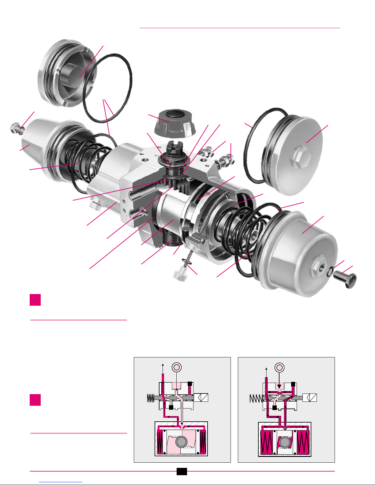
Numbers in brackets (#) refer to parts
on the exploded XL diagram (Fig. 1).
Read the relevant sections
carefully before continuing.
2 Mounting and
Operating
Instructions (Refer to Fig. 1)
2.1 Actuator to Valve Installation.
The mounting hole sizes and bolt hole
circle are to ISO 5211. These holes are
ISO METRIC COARSE on metric models
(UNC COARSE on imperial models for the
USA) as standard. When mounting the
Actuator to a Valve using a Mounting Kit,
the Pinion drive, coupling device and Valve
Stem should be centred and concentric to
prevent any side loading to the bottom
Pinion Radial Bearing and Valve Stem
Seal area.
Ensure that the square coupling shaft
to be operated is a close, but free
sliding fit into the female drive in the
Actuator shaft (4).
2.2 Maximum Operating Pressure.
XL models 45 to 2585
Do not exceed 8.2 bar (120 psi).
XL model 4580
Do not exceed 7 bar (100 psi).
2.3 Operating media.
Use clean, dry or lubricated air. Other
medias may be used, but consult your
local HYTORK VALVE AUTOMATION
CENTER for confirmation as to suitability.
Installation,
Operating and
Maintenance
Instructions
Installation, Operating and Maintenance Instructions XL Series Actuators
MAC099811
1
MAC099811
Fig. 2a
Fig. 2b
1
2
3
4
5
6
7
8
9
10
11
12
13
14
Quality
Assured
registered
management
systems
to ISO 9001
3 Piping
Instructions (Fig. 2a & 2b)
All Actuators can be either piped with solid
or flexible tubing with the Solenoid Valve
mounted remotely from the Actuator or
by mounting a NAMUR designed Solenoid
Valve DIRECTLY onto the NAMUR
Mounting Pad on the side of the Actuator.
(ALL Solenoids made to the NAMUR
standard can be mounted in this way.)
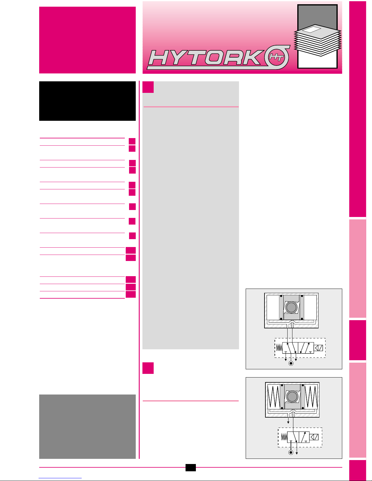
4 Solenoid Valves
on Spring Return
Actuators (Fig. 3a & 3b)
It is recommended that on Spring Return
Actuators, the HYTORK “CATS” Solenoid
Valves are used. These Valves are
specially designed to prevent
contamination of the internals of the
Actuator by dirt from the atmosphere.
This increases the working life of the
Actuator which reduces down time and
maintenance periods.
(See Dossier DSLxxxxx1)
2
Part
No. Component Quantity
1 Travel Stops & Seals 2
2 End Caps 2
3 Pistons 2
4 Pinion 1
5 Body 1
6 SAFEKEYS & ‘O’ Rings 2
7 Springs* 2, 3 or 4
8 Retractor Caps* 2
9 DURASTRIP Pinion Radial Bearings 2
bk DURASTRIP Piston Bearing Strips 2
Part
No. Component Quantity
bl Piston ‘O’ Rings 2
bm End Cap ‘O’ Rings 2
bn Pinion ‘O’ Rings 2
bo DURASTRIP Thrust Bearings 2
bp Steel Thrust Washers 2
bq Snap Ring (Circlip) 1
br Position Indicator 1
bs Sealing ‘O’ Rings* 2
bt Sealing Bolts* 2
*Spring Return Models only
1
2
bm
bm
bm
bobpbq
bobp
br
bs
bt
bt
9
9
7
8
7
6
3
4
2
2
2
bn
bn
bs
Fig. 1
spot pantone process yellow CV
spot pantone magenta
Fig. 3a
spot pantone process yellow CV
spot pantone magenta
Fig. 3b
Double
Acting
Spring
Return
5
bl
bk
3
5 Spares
Recommendations
When disassembling and carrying out
maintenance work on the XL Actuator, a
HYTORK XL Spares Kit must be used to
replace all ‘O’ Rings, DURASTRIP Bearing
Strips, Washers etc. This Kit is available
from HYTORK or its Stocking Distributors.
Important: Read Safety Instructions
before starting (see Section 1).
6 Complete
Disassembly -
Double Acting
Actuator
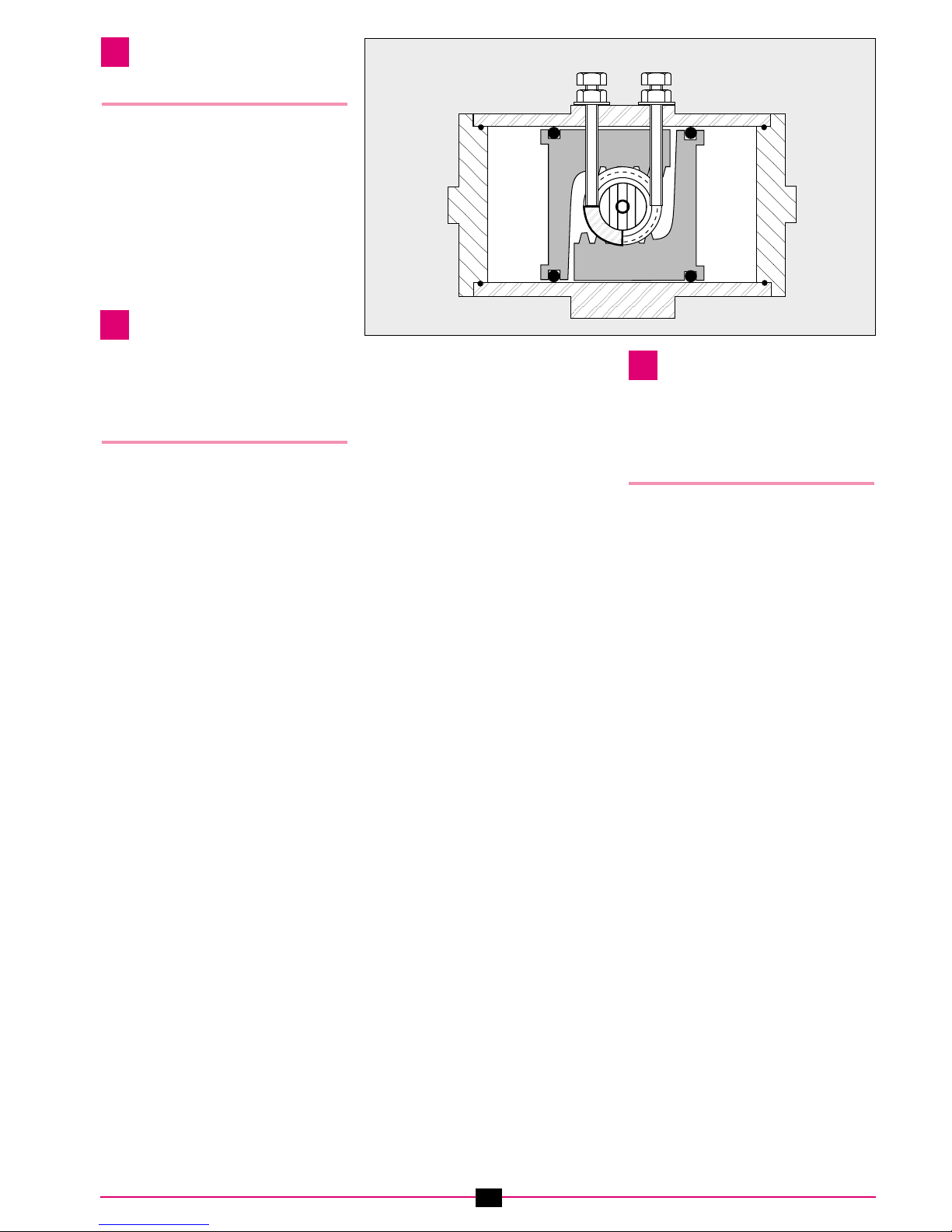
6.1 Removal of Travel Stops.
(Fig. 4)
Release the lock nut and remove both
Travel Stops and Seals (1) (cast Identity
numbers 1 & 2), which are located at the
top of the Actuator body (5) on the side
opposite the Actuator air connections.
6.2 Removal of End Caps.
Unscrew the two slotted SAFEKEY screws
(6) (cast Identity letters C & D) located in
the body next to each End Cap (2), and
gently pull them from the body, removing
each SAFEKEY. If the SAFEKEY screw
tends to spring, then rotate the End Cap
slightly to assist release. For larger
models (1125 to 4585) use a wrench
(spanner) on the End Cap to turn it to
assist the release of the SAFEKEY
(ensuring the End Cap is always flush to
the body). When both SAFEKEYS have
been removed, detach the Position
Indicator (17) from the top of the Pinion
and use a wrench (spanner) to rotate the
Pinion (4), driving the Pistons (3) apart
until they partially push the End Caps from
the body. Remove the End Caps by pulling
them free from the body, keeping them
square to the end face of the body.
6.3 Removal of Pistons.
Rotate the Pinion using a wrench (spanner)
to drive the Pistons apart until the Pinion
rotates freely. Rotate the Pistons in the
Actuator approximately 10 degrees.
Rotate the Pinion carefully with a little
force and the Pistons will push free of the
Actuator body. On later models of XL
Actuators, the Pistons are provided with
cast extraction holes in the face of the
Piston. By screwing the Travel Stop Bolt
into this hole it can be used to pull the
Pistons from the Actuator body using
pliers or vice grips.
6.4 Removal of Pinion.
On XL models 680, 1125 & 1370 with
Location Rings to ISO 5211 (metric
versions only), the Location Ring is a loose
item and must be removed before the
removal of the Pinion. Remove the Snap
Ring (Circlip) (16), Steel Thrust Washer
(15) and Thrust Bearing (14) from the top
of the Pinion and CAREFULLY remove the
Pinion from the cylinder body through the
bottom. (If the Actuator is a 680, 1125 or
1370 gently tap the top of the Pinion with
a rubber hammer to remove the Location
Ring first.) Care MUST be taken to ensure
that the Pinion Radial Bearing Strips (9) on
the top and bottom of the Pinion do not
become trapped in the bores during this
operation. Take care that the Pinion does
not damage the Pinion bores on removal.
If necessary, remove any burrs, etc. from
the top of the Pinion before removing it.
6.5 Inspection.
Clean and examine all parts for
damage and wear. Check SAFEKEYS for
damage and length (Fig. 10). HYTORK
recommends that ALL ‘O’ Rings, Bearing
Strips, Washers etc. are replaced using a
HYTORK XL Spares Kit.
7 Complete
Disassembly -
Spring Return
Actuator
7.1 Removal of Travel Stops.
(Fig. 4)
Release the lock nut and unscrew both
Travel Stops and Seals (1) (cast Identity
numbers 1 & 2), which are located at the
top of the Actuator body (5) on the side
opposite the Actuator air connections.
7.2 Removal of Spring Pack Modules.
(Fig. 5)
Remove Sealing Bolts (19) and ‘O’ Rings
(18) from each End Cap (2). Place the
HYTORK Retractor Rod (see Section
13.10) through the hole in the End Caps
and screw the Rod into the Spring
Retractor Caps (8) until travel is stopped,
the nut and washer being free of the End
Cap face. Screw the nut and washer
clockwise down the Retractor Rod until
they come up against the face of the End
Cap. Using a wrench (spanner), continue
to screw the nut clockwise down the Rod
exactly two turns, to draw the Spring
Retractor Cap away from the Piston
head (3). This compression of the Springs
releases the Spring force and unlocks the
SAFEKEY for removal. Repeat for the
other End Cap. Rotate the Caps to ensure
that the Springs are retracted; if the Cap
will not turn easily, screw the nut further.
Once the Retractor Rods have
compressed the Spring and the Caps can
be rotated freely, unscrew the two
SAFEKEY slotted screws (6) located in the
body (5) next to each End Cap to which
the SAFEKEYS (cast Identity letters C & D)
Travel Stop (1)
12
Viewed
from above
Pinion Slot
Body (5)
SAFEKEY C (6) SAFEKEY D (6)
End
Caps (2)
Double Acting
Fig. 4
 Loading...