

Hytorc BTM-0250-DOC, BTM-0750-DOC, BTM-2000-DOC, BTM-1000-DOC, BTM-3000-DOC Operation Manual

LITHIUM SERIES® Electric Torque Tool
(BTM-DOC Models)
Operations Manual
Mahwah, NJ 07430
USA
CATLITHIUM_SERIESMAN
800-FOR-HYTORC
(800-367-4986)
201-512-9500
hytorc.com333 Route 17 N.


TECHNICAL CERTIFICATIONS
Models
BTM-0250-DOC
BTM-0750-DOC
BTM-1000-DOC
BTM-2000-DOC
BTM-3000-DOC
Notice. The information contained in this document is subject to change without notice. HY TORC makes no warranty of any kind
with regard to this material, including but not limited to, the implied warranties of merchantability and fitness for a particular purpose.
HYTORC shall not be liable for errors contained herein or for incidental or consequential damages in connection with the furnishing,
performance, or use of this material. It is further recommended that the end-user or repair technician insure they have obtained and
are familiar with the latest revision of the manual for the equipment outlined in this document.
Restricted Rights Legend. Use and duplication of the information contained within this manual is limited to the purchaser, end user,
or licensed HYTORC representative. It is recommended that proper training for the equipment outlined in this manual be conducted
by a HYTORC-authorized training representative for any person who is operating or repairing the equipment outlined in this document. Modification of, or disclosure by any other agency or representative is strictly forbidden.
Product Modifications. HYTORC DOES NOT ALLOW any of the products listed in this manual to be modified by any end user without
exception. Should an application require a modification to the tool, or any of the standard accessories please consult with your local
HYTORC representative and they will be able to obtain the assistance for any modification that may be required.
Technical Certifications
Conforms to UL STDS 60745-1 & 60745-2-2
Certified to CSA STD C22.2 Nos. 60745-1 & 60745-2-2
For Hand-Held Motor-Operated Electric Tools.
EN ISO 12100-1:2011
EN ISO 12100-2:2011
EN ISO 14121-1:2007
EN ISO 11148-6:2012
5002282
LITHIUM SERIES® is a registered trademark of HYTORC.
Copyright © 2018 HYTORC All Rights Reserved. Reproduction, adaptation, or translation without prior written permission is prohib-
ited, except as allowed under the copyright laws.
Warranty. The LITHIUM SERIES Tool has a one-year limited warranty. Every tool is tested before leaving the factory and is warranted
to be free from defects in workmanship and materials. HYTORC will repair or replace, without charge, any tool which, upon examination, proves to be defective in workmanship or materials for one (1) year after the date of purchase. This warranty does not cover damage resulting from repairs made or attempted by unauthorized repair facilities. The repair and replacement remedies described herein
are exclusive. In no event shall HYTORC be liable for any incidental, special, or consequential damages, including loss of profits. This
warranty is exclusive and in lieu of all other warranties or conditions, written or oral, expressed or implied for merchantability or fitness
for particular use or purpose. This warranty gives you specific legal rights. You may also have other rights that vary from state to state
and province to province. In those states that do not allow the exclusion of implied warranties or limitation of incidental or consequential damages, the above limitations or exclusions may not apply to you. If you have questions about the warranty, contact our customer
service center at 201-828-5270.
Printed in the USA. April 2018
LITHIUM SERIES® Electric Torque Tool (BTM-DOC Models) Operations Manual
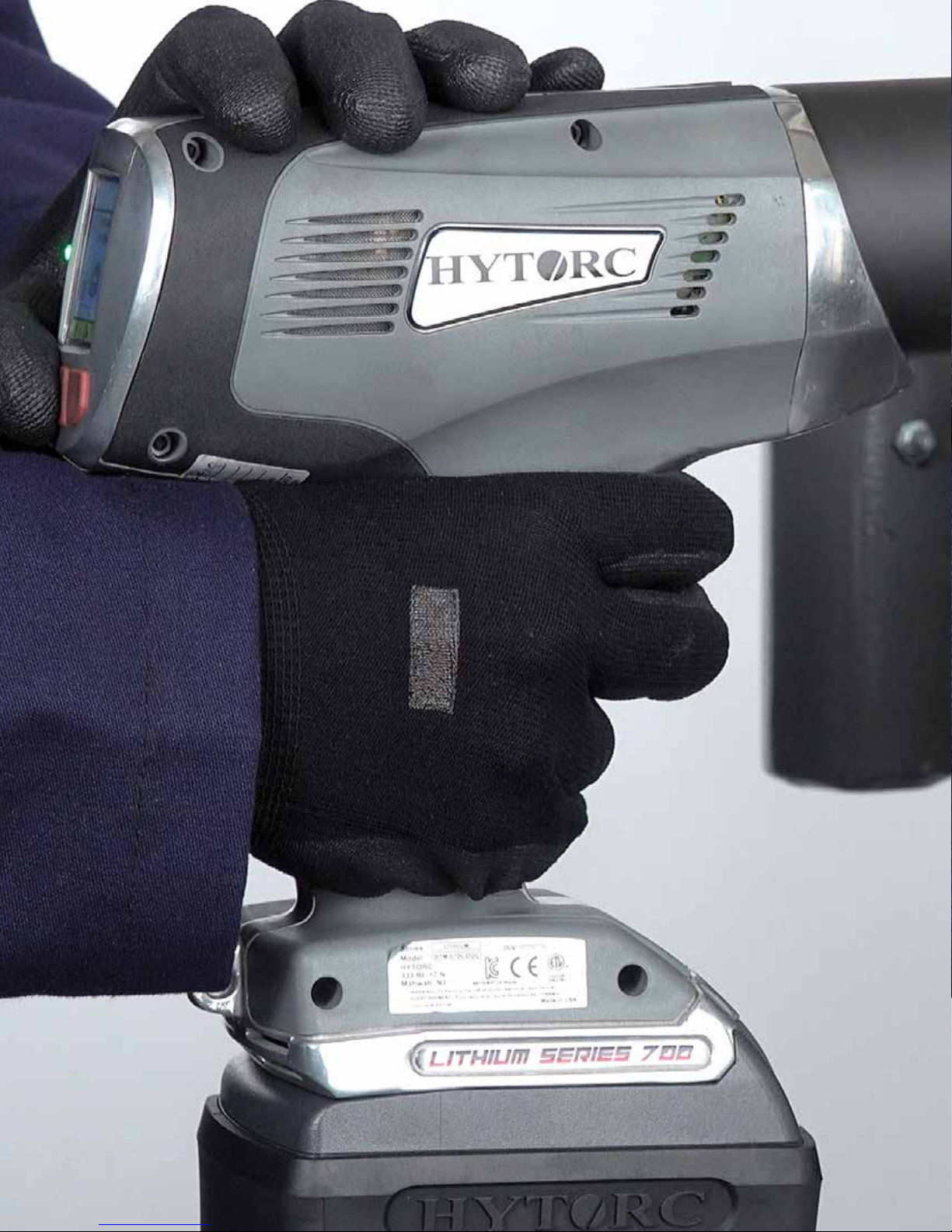

TABLE OF CONTENTS
1. IMPORTANT SAFETY INFORMATION
2. TOOL DESCRIPTION
3. SERVICE
FREE SERVICES
REPAIRS
TOOL RENTALS
HELP 11
FOLLOW US ONLINE 11
4. CARE AND HANDLING
INSPECT TOOLS & CALIBRATION
ENVIRONMENTAL CONSIDERATIONS
5. CHARGE, TEST & INSTALL BATTERY
CHARGE THE BATTERY
CHARGING INDICATOR
TEST THE BATTERY
INSTALL THE BATTERY
BATTERY RECYCLING
6. OPERATING THE CONTROL PANEL
PRIMARY CONTROL FEATURES
TOGGLE TORQUE, ANGLE & RELEASE
SET TORQUE
SET ANGLE
SET RELEASE 17
7. NAVIGATING THE MENUS
MAIN MENU AND SUBMENUS
OPERATION MENU
JOB DATA MENU
CONNECT USB CABLE
SAMPLE E XCEL FILE
SYSTEM MENU
ADMIN MENU
8. DUAL SPEED OPERATION
TWOSPEED OPERATION 27
DUALSPEED JOG
9. BOLTING WITH CONVENTIONAL REACTION ARM
INSTALL REACTION ARM
INSTALL SOCKET 29
CONVENTIONAL TORQUE SETUP
CONVENTIONAL TORQUE TIGHTENING
CONVENTIONAL TORQUE LOOSENING
10. BOLTING WITH THE HYTORC WASHER
INSTALL HY TORC WASHER DRIVER
TIGHTENING WITH THE HYTORC WASHER DRIVER
LOOSENING WITH THE HYTORC WASHER
11. BOLTING WITH THE HYTORC NUT
INSTALL HY TORC NUT DRIVER
TIGHTENING THE HYTORC NUT 36
LOOSENING THE HY TORC NUT
12. ADDENDUM IMPORTANT
LITHIUM SERIES® Electric Torque Tool (BTM-DOC Models) Operations Manual
LITHIUM SERIES® Electric Torque Tool (BTM-DOC Models) Operations Manual
5

. IMPORTANT SAFETY INFORMATION
Read and understand this material before operating or servicing the LITHIUM SERIES® Electronic Torque Tool. Failure to
understand how to safely operate this tool could result in an accident causing serious injury or death.
• Inspect all Tool components as they are removed from the shipping container. If damage is found to any component,
contact the shipper immediately. Do not use the tool.
• Failure to follow correct tool usage could result in personal injury, co-worker injury, and/or damaged tools and
equipment.
• Ensure your working area is clean and unobstructed before beginning work.
• Tool maintenance and repair must be performed by a qualified technician.
• Modifying a tool or tool accessory is dangerous and invalidates the warranty.
• Inspect the tool before each use. Have any obviously worn or damaged parts replaced.
• When not in use, store the tool and tool accessories in the plastic storage case supplied with the tool. Do not expose the
gun to high humidity or large temperature variations.
SAVE ALL WARNINGS AND INSTRUCTIONS FOR FUTURE REFERENCE
PERSONAL PROTECTIVE EQUIPMENT TOOL SAFETY WARNINGS
Always wear the appropriate personal protective equipment
when operating a tool including gloves, safety goggles,
hearing protection, hard hat, and safety shoes.
• Keep work area clean and well lit. Cluttered or dark areas invite accidents. Do not operate the tool in explosive
atmospheres, such as in the presence of flammable liquids, gases or dusts. The tool can create sparks which may
ignite the dusts or fumes.
• Keep children and bystanders away while operating the tool. Distractions can cause you to lose control.
6
Read all safety warnings and all instruction. Failure to follow
the warnings and instructions may result in electric shock,
fire, and/or serious injury.
WORK SAFETY AREA

PERSONAL SAFETY
• Stay alert, watch what you are doing and use
common sense when operating the tool. Do not use
the tool while you are tired or under the influence of
drugs, alcohol, or medication. A moment of inattention
while operating the tool may result in serious personal
injury.
• Use personal protective equipment. Always wear eye
protection. Protective equipment such as dust mask,
non-skid safety shoes, hard hat, or hearing protection
used for appropriate conditions will reduce personal
injuries.
• Prevent unintentional starting. Ensure the switch is
in the o-position before connecting to power source
and or battery pack, picking up or carrying the tool.
Carrying the tool with your finger on the switch or
energizing power tools that have the switch on invites
accidents.
LITHIUM TOOL USE AND CARE
• Do not force the tool. Use the correct tool for your
application. The correct tool will do the job better and
safe rat the rate for which it is designed.
• Do not use the tool if the switch does not turn it on
and o. Any tool that cannot be controlled with the
switch is dangerous and must be repaired.
• Disconnect the plug from the power source and/
or the battery pack from the tool before making
any adjustments, changing accessories, or storing
tool. Such preventive safety measures reduce the risk of
starting the tool accidentally.
• Store idle tools out of the reach of children and do
not allow persons unfamiliar with the tool or these
instructions to operate the tool. Tools are dangerous in
the hands of untrained users.
• Maintain tools. Check the misalignment or binding
of moving parts, breakage of parts and any other
condition that may aect the power of tool’s
operation. If damaged, have the tool repaired before
use. Many accidents are caused by poorly maintained
tool.
• Remove any adjusting key or wrench before turning
the tool on. A wrench or a key left attached to a rotating
part of the tool may result in personal injury.
• Do not overreach. Keep proper footing and balance
at all times. This enables better control of the tool in
unexpected situations.
• Dress properly. Do not wear loose clothing or jewelry.
Keep your hair, clothing and gloves away from the
moving parts. Loose clothes, jewelry or long hair can be
caught in moving parts.
• If devices are provided for the connection of dust
extraction and collection facilities, ensure these are
connected and properly used. Use of dust collection
can reduce dust-related hazards.
• Use the tool, accessories in accordance with these
instructions, taking into account the working
conditions and the work to be performed.
• Using the tool for the operations dierent from those
intended could result in a hazardous situation
• Rechargeable only with the charger specified by
manufacturer. A charger that is suitable for one type of
battery pack may create as risk of fire when used with
another battery pack.
• Use the tool only with specifically designated battery
packs. Use of any other battery pack my risk injury and
fire.
• When the battery pack is not in use, keep it away
from other metal objects, like paper clips, coins, keys,
nails, screws and other small metal objects that can
make a connection from one terminal to another.
Shorting the battery terminals together may cause burns
or a fire.
• Under abusive conditions, liquid may be ejected from
the battery; avoid contact. if contact accidentally
occurs, flush it with water. If liquid contacts eyes,
additionally seek medical help. Liquid ejected from the
battery may cause irritation or burns.
• Have your tool serviced by a qualified repair person using identical replacement parts. This will ensure that the
safety of the tool is maintained.
LITHIUM SERIES® Electric Torque Tool (BTM-DOC Models) Operations Manual
SERVICE
7

IMPORTANT BATTERY PACK INSTRUCTIONS
• Do not splash or immerse in water or other liquids.
• Do not incinerate the battery pack even if it is
severely damaged or is completely worn out. The
battery pack can explode in a fire. Toxic fumes and
materials are created when lithium ion battery packs are
burned.
• Do not charge or use the battery in explosive
atmospheres, such as in the presence of flammable
liquids, gases or dust. Inserting or removing the battery
from the charger may ignite dust or fumes.
• If battery contents come into contact with the skin,
immediately wash area with mild soap and water.
WARNING!
Burn hazard. Battery liquid may be flammable if exposed to spark or flame.
WARNING!
• If battery liquid gets into the eyes, rinse over the
open eye for 15 minutes or until irritation ceases. If
medical attention is needed, the battery electrolyte is
composed of a mixture of liquid organic carbonates and
lithium salts.
• Contents of opened battery cells may cause
respiratory irritation. Provide fresh air. If symptoms
persist, seek medical attention.
• Charge the battery packs only in battery chargers
supplied for charging this product.
• Do not pack with conductive items.
Fire hazard. Do not store or carry battery so that metal objects can contact exposed battery terminals.
For example, do not place battery in aprons, pockets, tool boxes, product kit boxes, drawers with
loose nails, screws, keys etc. Transporting batteries can possibly cause fires if the battery terminals
inadvertently come in contact with conductive materials such as keys, coins, hand tools and the like.
WARNING!
Never attempt to open the battery pack for any reason. If battery pack case is cracked or damaged,
do not insert into charger or tool. Do not crush, drop, or damage battery pack. Do not use a battery
pack or charger that has received a sharp blow, has been dropped or has been run over or damaged
in any way (i.e. pierced with a nail, hit with a hammer, stepped on). Damaged battery packs should be
returned to an authorized HYTORC service center for recycling.
US Department of Transportation Hazardous Materials Regulations
The US Department of Transportation Hazardous Materials Regulations (HMR) actually prohibit
transporting batteries in commerce or on airplanes, (i.e. packed in suitcases and carry-on luggage).
When transporting individual batteries, make sure that the battery terminals are protected and well
insulated from materials that could contact them and cause a short circuit. For any other concerns in
regarding the transportation of LI-ION batteries, consult your Transportation Carrier.
8

IMPORTANT BATTERY CHARGER SAFETY INSTRUCTIONS
• Before using charger, read all instructions and
cautionary markings on charger, battery pack and
product using battery pack.
• Do not attempt to charge the battery pack with any
chargers other than the one in this manual. The
charger and battery pack are specifically designed to
work together.
• These chargers are not intended for any uses other
than batteries supplied with LITHIUM SERIES Tools
as described in this manual. Any other uses may result
in risk of fire, electric shock or electrocution.
• Do not expose charger to rain or snow.
• To disconnect charger, firmly grasp plug and remove.
Do not disconnect the charger by pull-ing on the cord.
• Make sure the cord is located so that it will not be
stepped on, tripped over, or otherwise subjected to
damage or stress.
• Do not use an extension cord unless it is absolutely
necessary.
• An extension cord must have adequate wire size
(AWG) for safety. In general the larger the wire size the
greater the capacity of the cable.
• Do not block any ventilation slots on charger power
supply.
• DO NOT attempt to charge the battery pack with
any chargers other than the one in this manual. The
charger and battery pack are specifically designed to
work together.
• These chargers are not intended for any uses other
than batteries supplied with LITHIUM SERIES Tools
as described in this manual. Any other uses may result
in risk of fire, electric shock or electrocution.
• Do not expose charger to rain or snow.
• To disconnect charger, firmly grasp plug and remove.
Do not disconnect the charger by pull-ing on the cord.
• Make sure the cord is located so that it will not be
stepped on, tripped over, or otherwise subjected to
damage or stress.
• Do not use an extension cord unless it is absolutely
necessary.
• An extension cord must have adequate wire size
(AWG) for safety. In general the larger the wire size the
greater the capacity of the cable.
• Do not block any ventilation slots on charger power
supply.
WARNING!
Burn hazard. Battery liquid may be flammable if exposed to spark or flame.
WARNING!
Burn hazard. To reduce the risk of injury, charge only tool batteries. Other types of batteries may burst
causing personal injury and damage.
CAUTION!
Under certain conditions, with the charger plugged into the power supply, the charger can be
shorted by foreign material. Foreign materials of a conductive nature such as, but not limited to, steel
wool, aluminum foil, or any buildup of metallic particles should be kept away from charger cavities.
Always unplug the charger from the power supply when there is no battery pack in the cavity. Unplug
charger before attempting to clean.
LITHIUM SERIES® Electric Torque Tool (BTM-DOC Models) Operations Manual
9

. TOOL DESCRIPTION
Square Drive Compatible
with Standard Sockets
Reaction Spline
Planetary Gear Box
Dual Speed Switch
Trigger
Pistol Grip Handle
Battery Lock Button
Batter Test Button and
Charge Indicator
36V Rechargeable and
Interchangeable Battery
Cooling Vents
Brushed DC Motor and
Cooling Fans
USB Micro Port
Eyelet
PUSH-BUTTON CONTROL PANEL
The LITHIUM SERIES® Electric Torque Tool provides the following.
• High-strength planetary gear drive powered by brushed DC electric motor
• Two Speeds: Fast run-down, high powered torque.
• Electronic control and setup via push-button menu.
• Heads-Up LCD display.
• Ergonomic lightweight hand-held design with pistol-grip and trigger activation.
• Portable tool powered by rechargeable extended-life 36V lithium ion battery.
• Standard square-drive with dual-reaction spline.
• Integrated data acquisition and export capability.
10

. SERVICE
FREE SERVICES*
• User safety training upon receipt of merchandise
• Semi-Annual user safety training on request
• Annual safety seminar on appointment
• Loaner tools in event of product failure within 24 hours
• Torque/Tension consultation/seminar
• Half-Day, first-use supervision
• User training for first-time rentals
• Warranty repairs including return-freight
• Annual product inspection on request
• Product demonstrations
• 12-Month no-questions-asked warranty
• Upgrades during the lifetime of the tool to enhance
safety, durability, and function
*Above services are not subject to travel expense charges.
REPAIRS TOOL RENTALS
• All repairs are guaranteed for 6 months.
• All repairs are subject to labor and part cost as outlined
in the oicial HYTORC price list.
• All repairs will be tested and calibrated to ensure the
highest quality repairs.
• 100% of all paid rentals will be applied as a discount
towards any new purchase in that calendar year
• User training for first-time rentals is free of all cost
• Rental tools are guaranteed to perform and are subject
to the free loaner tool policy of HYTORC
• All warranty repairs are free of all charges including
return-freight.
HELP
If you require any further assistance, please call your local HY TORC Representative or 1-800-FOR-HYTORC
(1-800-367-4986). Please visit us at HYTORC.com.
FOLLOW US ONLINE
LITHIUM SERIES® Electric Torque Tool (BTM-DOC Models) Operations Manual
11
. CARE AND HANDLING
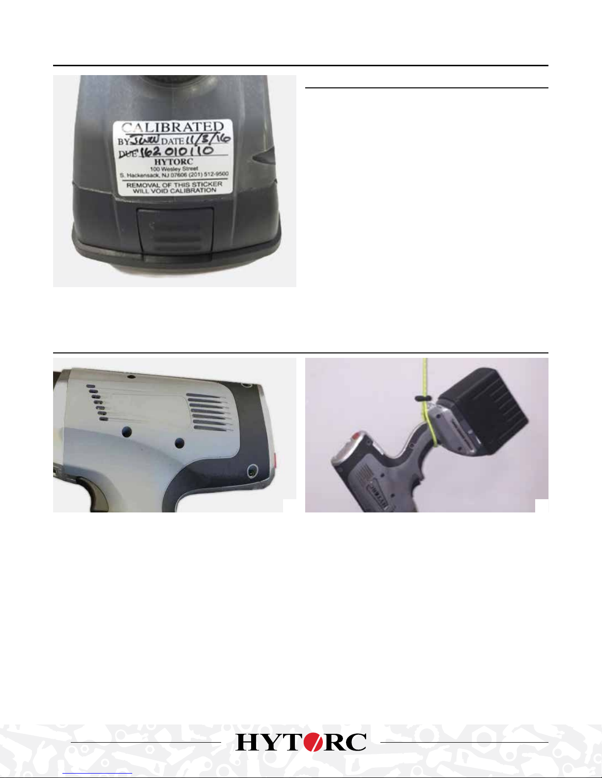
INSPECT TOOLS & CALIBRATION
• Inspect all components; if damaged report any sign of
damage to the shipper and do not use the tool.
• Inspect the tool before each use; repair or replace any
obviously worn or damaged parts.
• Maintenance must be performed by a qualified
technician.
• Modifying any of the components invalidates the
warranty.
• Check the calibration date on the tool. HY TORC
recommends tool recalibration annually.
• If more than a year has passed since last calibration,
contact HYTORC for recalibration.
• When not in use store all tool components in the plastic
storage case.
• Save all instructions and calibration reports in the
storage case.
ENVIRONMENTAL CONSIDERATIONS
1 2
The LITHIUM SERIES Tool is a rugged industrial tool with an electric motor and electronic control. The following
environmental considerations will help maintain reliable tool operation. Pictured above, keep cooling vents clear (1), and
secure the tool per local practice (2) to protect from dropping.
• The tool will withstand light splashing but do not submerge or subject to continuous rain or extreme humidity.
• The operating temperature of the tool should be less than 150°F.
• All Cooling Vents should be kept clear of dust, dirt and debris to allow internal fans to maintain airflow to keep the motor
and electronics within temperature limits, do not subject the tool to extreme dust environments that would clog the
vents or do not cover the vents with your hand.
• The tool and electronic components are not certified or approved for explosive environments or areas containing
combustible chemical materials.
12
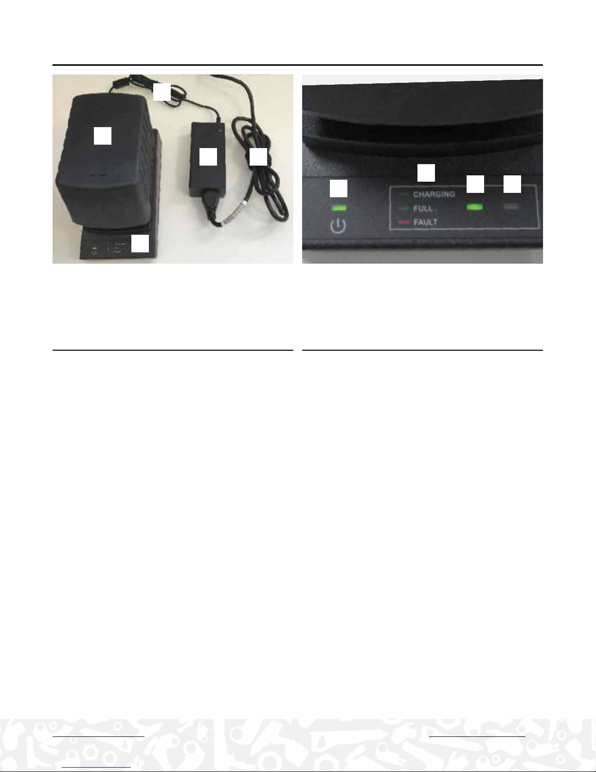
. CHARGE, TEST & INSTALL BATTERY
1
2
4 5
3
7
6
8 9
1. Charging Cable
2. Battery Pack
3. Charging Cradle
4. Power Supply
5. Power Supply Cord
6. Power Indicator
7. Legend
8. Charging Indicator
9. Fault Indicator
CHARGE THE BATTERY CHARGING INDICATOR
• The LITHIUM SERIES Tool is supplied with two long life
36 volt batteries and a charger.
• Before charging a battery verify the local voltage supply
to ensure capability with the charger; this will typically
be 110 Volts or 220 Volts AC.
• Connect the charging cradle to the power supply.
• Connect the power cord to a grounded outlet.
• If necessary connect the plug adapters for the local
power outlet.
• POWER INDICATOR green when charger is plugged into
AC outlet.
• CHARGING INDICATOR is flashing green while battery
is charging.
• CHARGING INDICATOR solid green when battery is fully
charged.
• FAULT INDICATOR is flashing red for battery fault not
charging.
• Battery is charged in approximately 90 minutes.
• Insert the battery by sliding it into the charger and
locking into place. The power indicator will be
illuminated green when plugged in.
• The charging indicator flashes green while charging and
turns solid green when the battery is fully charged.
• The 36 volt battery is fully charged in approximately 90
minutes.
LITHIUM SERIES® Electric Torque Tool (BTM-DOC Models) Operations Manual
13

TEST THE BATTERY
INSTALL THE BATTERY
• The Lithium-Ion battery has a long run life and will
power the tool at full speed until the battery is depleted,
so there is no gradual drop in power during use.
• For continuous use, have one or more spare battery
packs charging while the tool is in use. When need
simply swap batteries from the charger to the tool.
• Batteries can be charged hundreds of times without any
noticeable loss in capacity
• Batteries can be returned at no charge for recycling at
HYTORC locations or local recycling centers.
1. Push the TEST button on the side of the battery and
the LED’s will provide an approximate indicator of
remaining battery life:
1 LED On ≤ 25% Battery Charge Left
2 LEDs On ≤ 50% Battery Charge Left
3 LEDs On ≤ 75% Battery Charge Left
4 LEDs On ≤ 100% Battery Charge Left
The battery easily slides onto the tool
body and snaps into place.
1. Press the release button on the
battery and slide battery pack o
the charger.
2. Align the base of the tool with the
rails in the battery and slide the
battery pack firmly into the handle
until you hear (or see) the lock
snap in place.
3. To remove the battery pack from
the tool, press the release button
on the battery and firmly pull the
battery pack out of the tool.
BATTERY RECYCLING
The RBRC (Rechargeable Battery Recycling Corporation) Seal on the lithium ion battery (or battery pack) indicates that the
costs to recycle the battery (or battery pack) at the end of its useful life have already been paid by HYTORC The RBRC, in
cooperation with HYTORC and other battery users, has established programs in the United States to facilitate the collection
of spent lithium ion batteries. Help protect our environment and conserve natural resources by returning the spent lithium
ion battery to an authorized HYTORC service center for recycling. You may also contact your local recycling center for
information on where to drop o the spent battery. RBRC is a registered trademark of the Rechargeable Battery Recycling
Corporation.
14
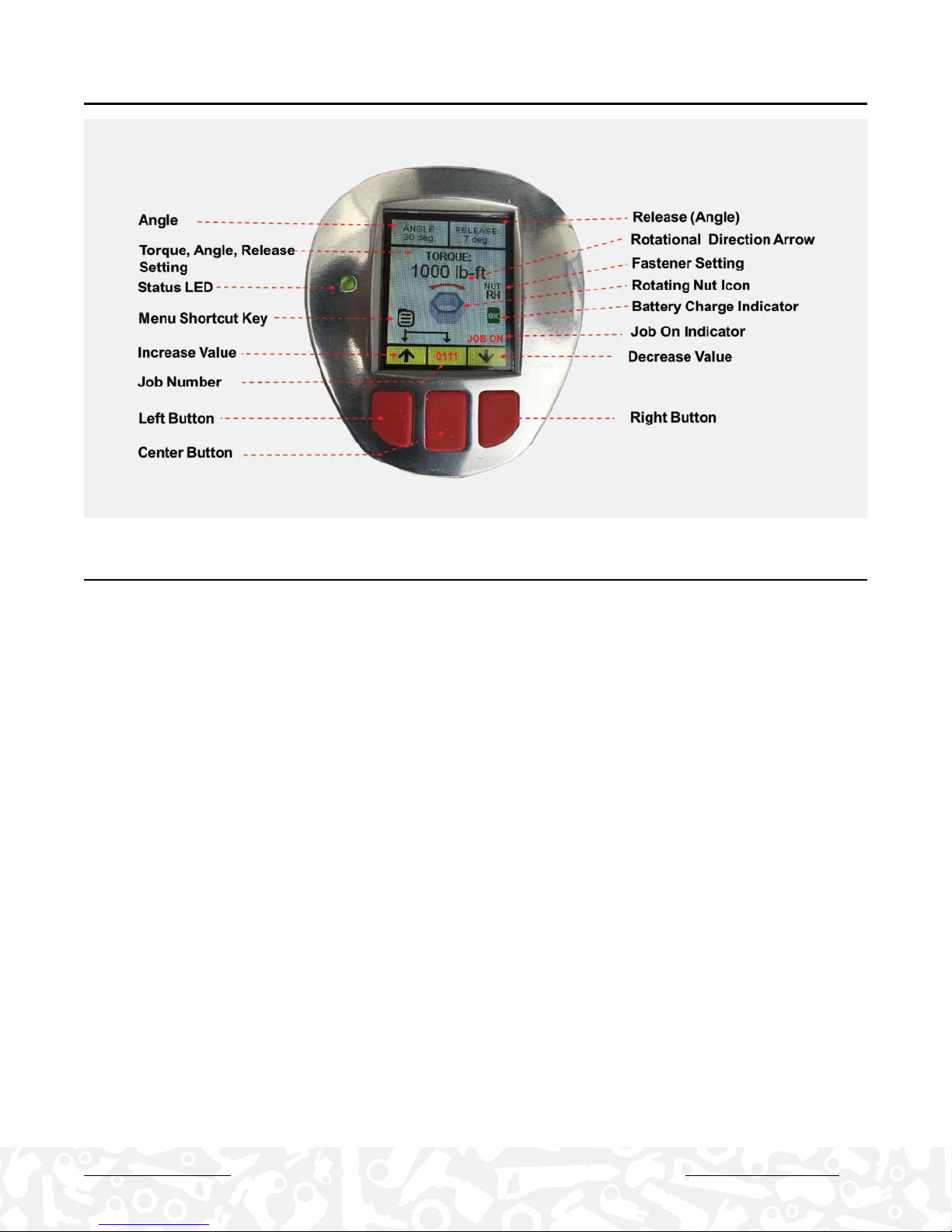
. OPERATING THE CONTROL PANEL
PRIMARY CONTROL FEATURES
• Press Any Button to Power-On Tool (the tool automatically turns o after 5 min)
• A new tool shows the factory default settings
• A tool that has been used before displays the last settings used on the tool before it was powered o .
• Left Button Increases the Torque Value
• Right Button Decreases the Torque Value
• Screen Features; Torque, Angle, Release, Direction, Battery Status, Fastener Type, Data Record Indicator
• Push and hold center button to cycle; TORQUE, ANGLE and RELEASE
• Hold 2 Left Buttons to display main and sub-menu options
LITHIUM SERIES® Electric Torque Tool (BTM-DOC Models) Operations Manual
15

TOGGLE TORQUE, ANGLE & RELEASE
The tool provides simple access to set Torque, Angle and Release by toggling the center button. The torque setup screen is
the home screen for operating the tool.
1. TORQUE: Press and hold the center button for
approximately 3-seconds and release it to access the
Angle screen.
2. ANGLE: Press and hold the center button for
approximately 3-seconds and release it to access the
Release screen.
16
3. RELEASE: Press and hold the center button for
approximately 3-seconds and release it to access the
Torque screen.

SET TORQUE
• Set the Torque Value is set by simply pushing the left button f to increase the torque or by pushing the right button i to
decrease the torque.
• Torque may be set to any value from the minimum to the maximum capability of the tool (or MAX MIN Torque Limits set
in the ADMIN menu).
• Output units may be displayed in lb-ft, N-m, kgf-m or %. (See output unit settings under the ADMIN menu)
• The Torque rotational direction arrow and the rotating nut icon reflect the fastener clockwise or counter clockwise
rotation associate with the specific fastener type. (The fastener type may be set under the Operation – Fastener Type
menu: Right-Hand, Left-Hand, HYTORC NUT and HYTORC Washer).
SET ANGLE
• Certain bolt tightening specifications may require an Angle Value in-addition to or instead of a Torque Value.
• The tool provides the ability to set an Angle value anywhere from 0 degrees to 360 degrees.
• The Angle Value is increased simply by pushing the left button
f to increase the angle or by pushing the right button i
to decrease the angle.
• If an Angle Value is set the gun will add the desired angle of rotation by applying additional torque after the completed
torque operation up to the maximum output of the tool.
• The angle feature is actuated by continuing to hold the trigger after the tool successfully completes the TORQUE.
• The angle force is applied after a time delay set in the Angle Delay menu – typical ½ second to 3 seconds.
SET RELEASE
• When the tool achieves the TORQUE value (and ANGLE if set) the motor automatically stalls and the gear box continues
to exert force (and reaction force) essentially locking the tool onto the nut.
• The gun provides a feature to release the tool from the nut by setting a RELEASE Angle to reverse the motor slightly thus
taking the applied force o the gear box and reaction point and releasing the tool from the nut without loosening the nut.
• The RELEASE Angle Setting may vary depending on the application and may need to be developed iteratively by testing
the value on the application; the objective is to set the minimum RELEASE angle required to release the tool without
applying a force in the opposite direction that would turn or loosen the nut.
• While the tool has a capability to set the RELEASE between 0 and 359 degrees, the RELEASE is typically set on the lower
end and less than 10 degrees (1-to-3 degrees for HYTORC Washer, or 3-to-7 degrees for reaction arms) so that nut is not
loosened. Under certain conditions the operator may need higher RELEASE Angle settings and these should be verified
to make sure that the nut is not being loosened by the higher setting.
• The automatic release feature is actuated by continuing to hold the trigger after the tool successfully completes TORQUE
(and ANGLE if set).
• During the operation the screen will change to show the release angle and direction, the tool motor will reverse by the
desired release angle and then stall again to allow the tool to be removed from the nut.
• The RELEASE Angle is applied following application of TORQE (and ANGLE if set) and after an additional time delay set
in the Angle Delay menu – typical ½ second to 3 seconds.
LITHIUM SERIES® Electric Torque Tool (BTM-DOC Models) Operations Manual
17
. NAVIGATING THE MENUS
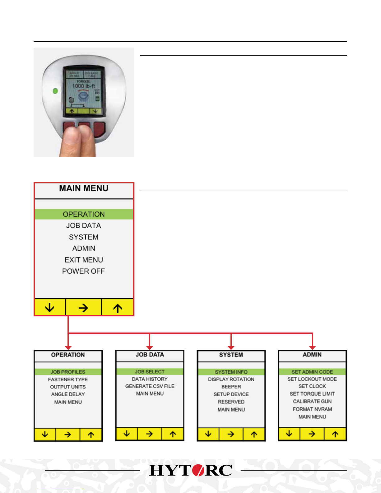
MAIN MENU AND SUBMENUS
The Main Menu provides Operations, Job Data, System, Admin and the Exit and
Power O options.
Press and hold the left and center buttons simultaneously for approximately
three seconds, release buttons when the Main Menu is displayed.
MAIN MENU
• The green bar highlights the current position
• Press left button f to scroll down, right button to scroll up
• Press the center button i to select and display a sub-menu
18

OPERATION MENU
The Operation menu contains most functions for everyday operation.
• The green bar highlights the current position
• Press left button f to scroll down, right button to scroll up
• Press the center button i to select and display a sub-menu
(Continued on following page)
In order to save or load a job profile the
user must first enter the 4-digit code to
unlock the tool. To enter the code press
button to increase the digit or i to
decrease the digit, press to advance
to the next digit until the correct code
is entered (default 0000). When the
4-digit code is entered correctly press
again to JOB PROFILES.
NOTE: Wrong code returns user to
previous screen. There is no limit on
number of attempts. See administrator
for correct code.
Allows the user to save tool parameters
to memory as a Saved Job Profile (SJP),
or to load previously saved parameters
(SJPs) from memory.
The tool can save up to 8 job profiles;
each profile includes saved values for
TORQUE (T), ANGLE (A), RELEASE (R)
and fastener type. Scroll and select the
desired setup values – then select ,
or if saving new setup values select
to access submenu to either SAVE or
LOAD settings.
The user can SAVE the settings
currently on the home display – now
shown in SAVE settings - by pushing
the left button i also adds the profile to
the top of JOB PROFILES.
Alternatively, the user can LOAD the
selected profile – now shown in LOAD
settings - by pushing the right button
. Exit without load or save by hitting
the center button X. Return to the
OPERATION Menu upon completion.
LITHIUM SERIES® Electric Torque Tool (BTM-DOC Models) Operations Manual
19

(OPERATION MENU continued from previous page)
Press appropriate button i to scroll
up or down, push to select fastener
type:
RH RIGHT HAND bolts tightened
clockwise.
LH LEFT HAND bolts tightened
counterclockwise.
HN HYTORC NUT tightened
counterclockwise.
HW HYTORC WASHER tightened
clockwise.
Any selection returns users to
OPERATION menu.
NOTE: When using the HYTORC
Washer or HYTORC Nut the safety
feature requiring a push of the button
before operation is disabled. Tool
should never be used with a reaction
arm in this setting.
Allows the operator to select the
preferred units of the torque display.
Press buttons to scroll i or to
highlight the desired units, press to
select desired units and return to the
OPERATION menu.
The user can adjust the time delay for
applying the ANGLE and RELEASE
following the TORQUE operation – the
delay can range from 0ms to 3000ms.
The time delay is applied after the
TORQUE value by continuing to hold
the trigger.
Push up button to increase the delay
or down button i to decrease the delay.
Select to return to the OPERATION
menu.
20

JOB DATA MENU
The Job Data menu contains settings needed to record and download data from
the tool.
• The green bar highlights the current position
• Press left button f to scroll down, right button to scroll up
• Press the center button i to select and display a sub-menu
(Continued on following page)
In order to record data the user must
first enter the 4-digit UNLOCK CODE to
unlock the tool.
To enter the code press button to
increase the digit or i to decrease the
digit, press to advance to the next
digit until the correct code is entered
(default 0000).
When the correct 4-digit code is
entered press again to proceed to
SET RECORDING MODE.
NOTE: Wrong code returns user to
previous screen. There is no limit on
number of attempts. See administrator
for correct code.
User selects JOB NUMBER to turn on
Data Recording for a particular job.
After selecting JOB NUMBER the user
is prompted for a 4-digit job number to
begin recording data.
Alternatively, the user may select END
JOBS to stop recording.
The user is asked to enter a 4-digit JOB
NUMBER (0001 to 9999) for identifying
the data record.
To enter the job number press to
increase the digit or i to decrease the
digit, press to advance to the next
digit until the code is entered.
Press to begin DATA RECORDING
and return to the JOB DATA menu. The
tool is now recording and the JOB ON
and JOB NUMBER are now displayed
on the home screen to indicate the tool
is now recording all job data.
LITHIUM SERIES® Electric Torque Tool (BTM-DOC Models) Operations Manual
21

(JOB DATA MENU continued from previous page)
Provides a summary of jobs and events
currently being saved in memory.
Press the buttons i to scroll through
the job numbers to select the data
set you want to download. Press to
select the job number and to generate
the CSV file.
This screen prompts the user to
connect a standard USB cable between
the PC (Type A) to the tool (Micro A).
The tool is discovered by the PC just
as any mass storage device. The PC
will display a folder allowing the user to
click to open the JOB DAT file in Excel
format.
The file serves as an electronic record
of the JOB DATA. When done, press
button to exit the GENERATE CSV
FILE mode and return to the JOB DATA
menu.
22

CONNECT USB CABLE
SAMPLE EXCEL FILE
DATE TIME EVENT TORQUE
18-0 2-31 21:27:40 2 310 — 15 90 7 12 0 G LOOSEN HN F T.- LB S.
18-0 2-31 21: 27:4 8 2 310 — 15 90 7 6 0 G TIGHTEN HN F T.-L BS .
18-0 2-31 22:07:3 5 2 310 — 15 90 7 8 0 G LOOSEN HN F T.- LB S.
18-0 2-31 22 :10:3 8 2 310 — 15 90 7 5 0 G LOOSEN HN FT.-LB S.
LITHIUM SERIES® Electric Torque Tool (BTM-DOC Models) Operations Manual
TORQUE
CHECK
ANGLE RELEASE JOB DURATION TEMP VOLTAGE TL FASTENER
TORQUE
UNITS
COMPCODE
PREMATURE
TRIGGER
RELEASE
PREMATURE
TRIGGER
RELEASE
PREMATURE
TRIGGER
RELEASE
PREMATURE
TRIGGER
RELEASE
23

SYSTEM MENU
The SYSTEM menu contains additional settings for tool configuration.
• The green bar highlights the current position
• Press left button f to scroll down, right button to scroll up
• Press the center button i to select and display a sub-menu
NOTE: The SET UP DEVICE and DIAGNOSTIC Menu items are not intended for field use.
These functions are password protected and only accessible by HYTORC in the factory.
Displays Firmware (FW) and Hardware
(HW) versions for MDC (Motor Drive
Control) And UIC (User Interface
Control).
Press any button to return to SYSTEM
menu.
Provides capability to orient the display
in normal or inverted mode:
NORMAL Screen is legible when
battery is down.
INVERT Screen is legible when battery
is up.
INVERT FOR CAL Inverted for
calibration
Scroll down i or scroll up to reach
desired orientation for the display and
push to select the orientation and
return to the SYSTEM SETTINGS menu.
The user can optionally enable or
disable the beeper.
Press buttons to scroll i or to
highlight the desired state for the
beeper, press to select beep OFF or
ON and return to the ADMIN menu.
If turned on, the beeper will sound one
time for each successful operation and
4 times to indicate an error.
24

ADMIN MENU
The ADMIN menu contains less seldom used features or those typically only
configured by an administrator or supervisor.
• The green bar highlights the current position
• Press left button f to scroll down, right button to scroll up
• Press the center button i to select and display a sub-menu
NOTE: The CALIBRATE GUN and FORMAT NVRAM options are not intended for field
use, these are only accessed by HYTORC authorized service personnel.
(Continued on following page)
The user is prompted
to select either
SYSTEM or GENERAL
access level.
The SYSTEM level is
only used by certified
personnel for
calibrating the tool.
The GENERAL level
password is assigned
by an administrator
to provide security for
setting torque limits,
setting the clock and
putting the tool in
lockout mode.
System level user must first enter the old 4 digit
unlock code (default 0000) for access and then
enter a new unlock code for system access.
NOTE: When System password is entered the
General password is cleared to 0000.
General administrator must first enter the old
4-digit unlock code (default 0000) for access
and then enter a new unlock code for system
access.
LITHIUM SERIES® Electric Torque Tool (BTM-DOC Models) Operations Manual
25

(ADMIN MENU continued from previous page)
ENTER GENERAL
PASSWORD
The user may enable a
lockout mode that prevents
any user from changing
any parameter except
directional control. This
allows the administrator
to lock the tool at desired
settings for various
users. Press the buttons
i to scroll to ENABLE
or DISABLE lockout
mode, press to select
LOCKOUT MODE and
return to the ADMIN menu
ENTER GENERAL
PASSWORD
Allows user to set time
and date by entering
appropriate numerical
values.
Press up button
increases the value
and down button i
to decrease the value,
select to advance to
the next numerical value,
after setting year push
to return to SYSTEMS
SETTINGS menu.
ENTER GENERAL
PASSWORD
To adjust the minimum
TORQUE limit press button
to increase the value or i
to decrease the value.
Press to save the lower
torque limit – screen
flashes “Saving setting”
and then displays the
upper torque limit screen.
To adjust the maximum
TORQUE limit press button
to increase the value or i
to decrease the value.
Press to save the upper
torque limit – screen
flashes “Saving setting”
and then exits to ADMIN
menu.
26

. DUAL SPEED OPERATION
TWOSPEED OPERATION
Each LITHIUM SERIES Tool is equipped with a dual-speed gearbox. The gearbox has two modes:
1. RUNDOWN MODE: The gearbox is set to run at a higher speed and very
low torque to run nuts down to seated position prior to tightening on an
application. This mode applies a very small amount of torque just to overcome
the resistance of running nuts down onto bolts for a short duration.
2. TORQUE MODE: Used for to apply high torque to fully tighten bolts with
required loads.
The tool is switched between TORQUE and RUNDOWN by setting the dual speed
switch beneath the barrel of the tool. Switch to TORQUE for torque operations,
and RUNDOWN to run down nuts. Always be sure the switch is fully engaged in
either position, never in the middle.
DUAL SPEED JOG
In the event the gear selector does not engage, a JOG FORWARD or JOG REVERSE screen will be displayed. Press the
trigger briefly to synchronize the gears and re-engage the drive mechanism.
JOG FORWARD JOG REVERSE
LITHIUM SERIES® Electric Torque Tool (BTM-DOC Models) Operations Manual
27
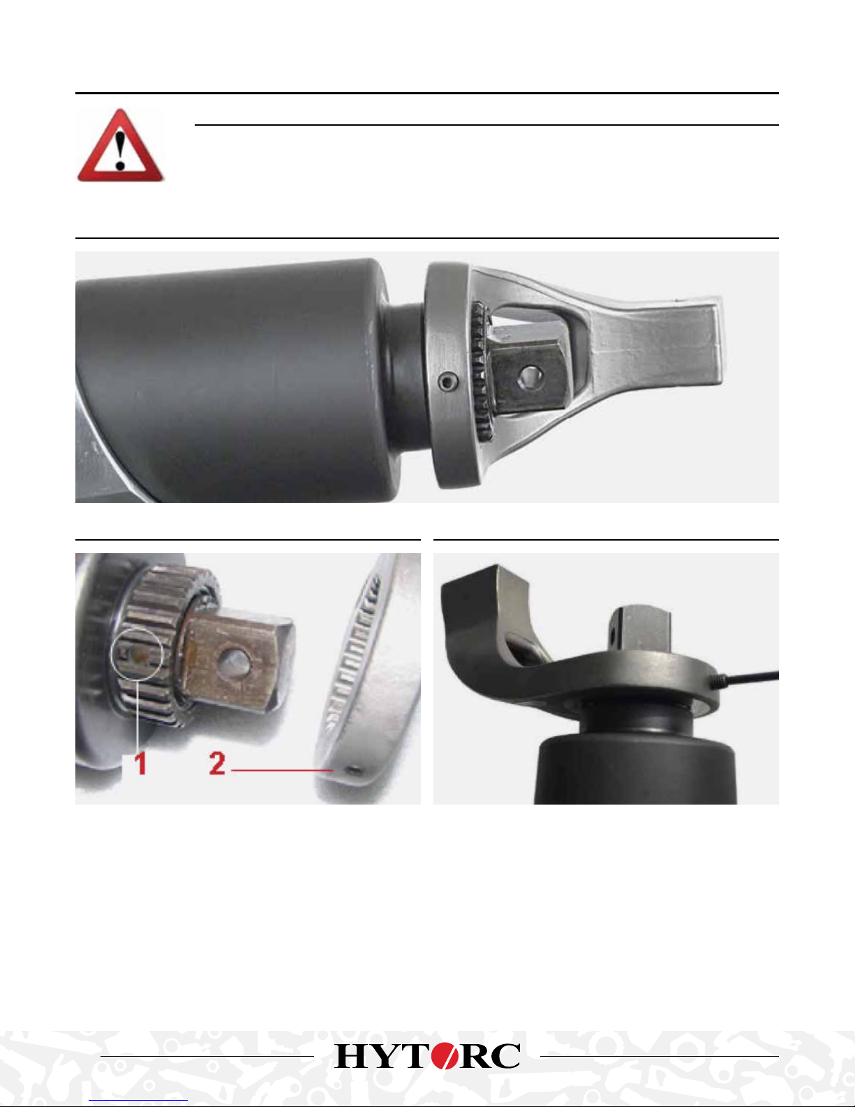
. BOLTING WITH CONVENTIONAL REACTION ARM
WARNING!
Failure to make sure the reaction arm is in direct contact with an immovable object before fastening
could result in serious injury. Make sure that no part of your body is in the path of the reaction arm
when the nut is tightened to avoid injury.
INSTALL REACTION ARM
. FLAT ON REACTION SPLINE. . ALLEN SET SCREW TIGHTEN ALLEN SET SCREW
The LITHIUM SERIES Tool is easily configured for conventional torque applications with standard sockets and reaction arms.
• The reaction arm is quickly secured to the tool
• Slide the reaction arm over the drive while aligning the set screw with the flat on the Spline
• Tighten the set screw to firmly attach the reaction arm.
• Challenge the reaction arm to make sure it is firmly secured.
• Never modify a reaction arm as this may lead to personal injury or damage to the tool.
28

INSTALL SOCKET
• Set the Torque Value is set by simply pushing the left button
f to increase the torque or by pushing the right button i
to decrease the torque.
• Torque may be set to any value from the minimum to the maximum capability of the tool (or MAX MIN Torque Limits set
in the ADMIN menu).
• Output units may be displayed in lb-ft, N-m, kgf-m or %. (See output unit settings under the ADMIN menu)
• The Torque rotational direction arrow and the rotating nut icon reflect the fastener clockwise or counter clockwise
rotation associate with the specific fastener type. (The fastener type may be set under the Operation – Fastener Type
menu: Right-Hand, Left-Hand, HYTORC NUT and HYTORC Washer).
CONVENTIONAL TORQUE SETUP
• Power on the tool, adjust the settings and select
fastener. For conventional torque applications the
fastener will be right or left hand.
• If necessary set the speed switch to RUN DOWN to
quickly run down the nuts until they are flush against
the flange.
• Prior to applying torque, position a back wrench to
prevent the back nut from turning during tightening.
• Place the socket on the nut, making sure to fully
engage the nut.
• Make sure the reaction arm is firmly abutted against a
stationary object before applying torque.
LITHIUM SERIES® Electric Torque Tool (BTM-DOC Models) Operations Manual
29
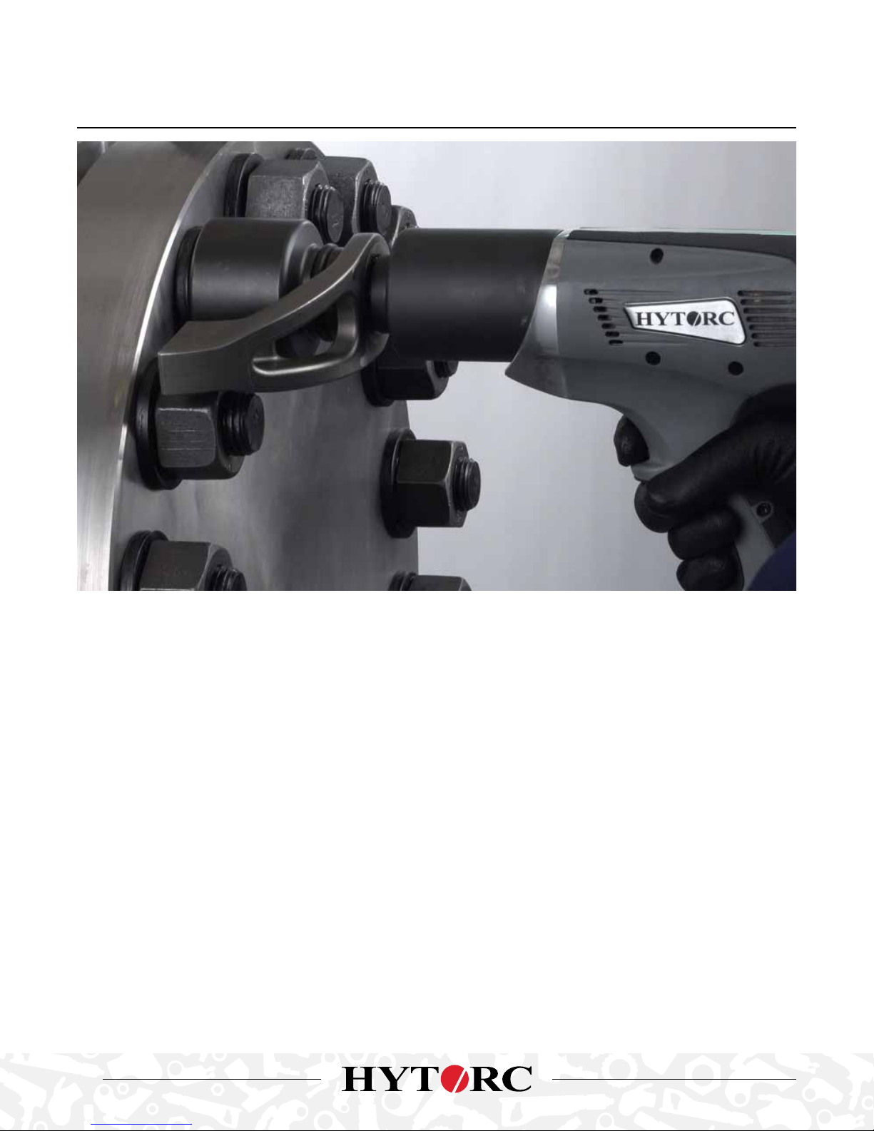
CONVENTIONAL TORQUE TIGHTENING
• To begin the TORQUE operation, pull and hold the trigger.
• With Right or Left Fasteners, a message is displayed instructing the user press an additional button on the control panel
to ensure the operator keeps both hands clear of the reaction arm.
• As soon as the user pushes the drive will turn.
• Once the tool starts the reaction arm will move to firmly press against the reaction surface and then the tool will begin
applying torque and tighten the nut.
• Continue holding the trigger until the tool reaches the desired torque and stops.
• If an ANGLE has been specified, continue holding the trigger, the tool will pause and restart after the angle delay.
• If a RELEASE has been specified, continue holding the trigger, the tool will pause and restart after the angle delay.
• Release the trigger after the tool has completed all specified operations.
• The status light turn amber during operation. If the operation is successful, the status light will turn green,
if unsuccessful the status light will turn red.
• If the BEEPER is enabled the tool will provide an audible beep upon completion of the operations.
• Remove the tool socket from the nut.
• Should torque be applied without a release angle the tool may lock onto the nut. If this happens set the tool to loosen to
free the tool and repeat the tighten operation.
30

CONVENTIONAL TORQUE LOOSENING
• The Tool provides the maximum torque capacity in reverse providing a powerful breakout capability.
• Press the center button to toggle to the loosen mode.
• When using conventional torque install a back wrench to keep the back nut from turning.
• Position the tool over the nut.
• Position the reaction arm against a firm surface.
• Pull and hold the trigger and any button on the rear panel to apply torque to loosen the nut.
• Once the tool starts the reaction arm will move and firmly press against the reaction surface. The tool will then begin
applying torque to loosen the nut.
• The status light turn amber during operation. If the operation is successful, the status light will turn green, if
unsuccessful the status light will turn red.
• Remove the tool driver from the nut.
LITHIUM SERIES® Electric Torque Tool (BTM-DOC Models) Operations Manual
31

. BOLTING WITH THE HYTORC WASHER
INSTALL THE HYTORC WASHER DRIVER
• The LITHIUM SERIES Tool is easily configured for
tightening bolts where the HYTORC Washer is used.
• Identify the appropriate size HYTORC Washer Driver.
• Slide the washer driver over the square drive and spline
while aligning the thumb screw with the flat on the spline.
• Tighten the thumb screw to secure the Driver.
• Challenge the driver to make sure it is securely attached.
32

TIGHTENING WITH THE HYTORC WASHER DRIVER
• Power on the tool, adjust tool settings and set the
fastener type to HYTORC WASHER.
• If necessary set the speed switch to RUN DOWN to
quickly run down the nuts until they are flush against the
flange. Set the speed switch back to Torque after the
run down is complete.
• Position the tool over the nut and HYTORC Reaction
Washer.
• Pull the trigger to apply torque until the tool reaches the
desired torque and stops.
• If an ANGLE has been specified, continue holding the
trigger, the tool will pause and restart after the angle
delay.
• If a RELEASE has been specified, continue holding the
trigger, the tool will pause and restart after the angle
delay.
• Release the trigger after the tool has completed all
specified operations.
• During the operation the status light turn amber during
operation. If the operation is successful the status light
will turn green, if unsuccessful the status light will turn
red
• If the BEEPER is enabled the tool will provide an audible
beep upon completion of the operations.
• Remove the tool socket from the nut.
• Should torque be applied without a release angle the
tool may lock onto the nut. If this happens set the tool to
loosen to free the tool and repeat the tighten operation.
LITHIUM SERIES® Electric Torque Tool (BTM-DOC Models) Operations Manual
33

LOOSENING WITH THE HYTORC WASHER DRIVER
• The Tool provides the maximum torque capacity in reverse providing a powerful breakout capability.
• Press the center button to toggle to the loosen mode.
• Position the driver over the nut and HYTORC reaction washer and hold the trigger and begin applying torque.
• During the operation the status light turn amber during operation. If the operation is successful the status light will turn
green, if unsuccessful the status light will turn red
• Remove the tool driver from the nut.
34

. BOLTING WITH THE HYTORC NUT
INSTALL THE HYTORC NUT DRIVER
• The LITHIUM SERIES Tool is easily configured for tightening HYTORC Nuts.
• Identify the appropriate size HYTORC Nut Driver
• Slide the nut driver over the square drive and spline while aligning the set screw with the flat on the spline.
• Tighten the set screw to secure Nut Driver.
• Challenge the nut driver to make sure it is securely attached.
LITHIUM SERIES® Electric Torque Tool (BTM-DOC Models) Operations Manual
35

TIGHTENING THE HYTORC NUT
NOTE: The HYTORC Nut inner sleeve is tightened in the counter clockwise direction (left hand threads).
• Power on the tool, adjust tool settings and set the fastener type to HYTORC Nut.
• Position the tool over the nut.
• Pull the trigger to apply torque until the tool stalls at the specified torque
• If a RELEASE ANGLE has been specified continue holding the trigger and the tool will restart and then stall again after
completing the RELEASE angle. Then the tool can be released from the nut.
• Release the trigger after the tool has completed all specified operations.
• The status light turn amber during operation. If the operation is successful, the status light will turn green, if
unsuccessful the status light will turn red.
• If the BEEPER is enabled the tool will provide an audible beep upon completion of the operations.
• Remove the tool socket from the nut.
• Should torque be applied without a release angle the tool may lock onto the nut. If this happens set the tool to loosen to
free the tool and repeat the tighten operation.
36

LOOSENING THE HYTORC NUT
• The Tool provides the maximum torque capacity in reverse providing a powerful breakout capability.
• Press the center button to toggle to the loosen mode.
• It may necessary to install a back wrench to keep the back nut from turning.
• When loosening HYTORC Nuts position the driver and hold the trigger until the HYTORC Nut is loose.
• The status light turn amber during operation. If the operation is successful, the status light will turn green, if
unsuccessful the status light will turn red.
• Remove the tool driver from the nut.
LITHIUM SERIES® Electric Torque Tool (BTM-DOC Models) Operations Manual
37
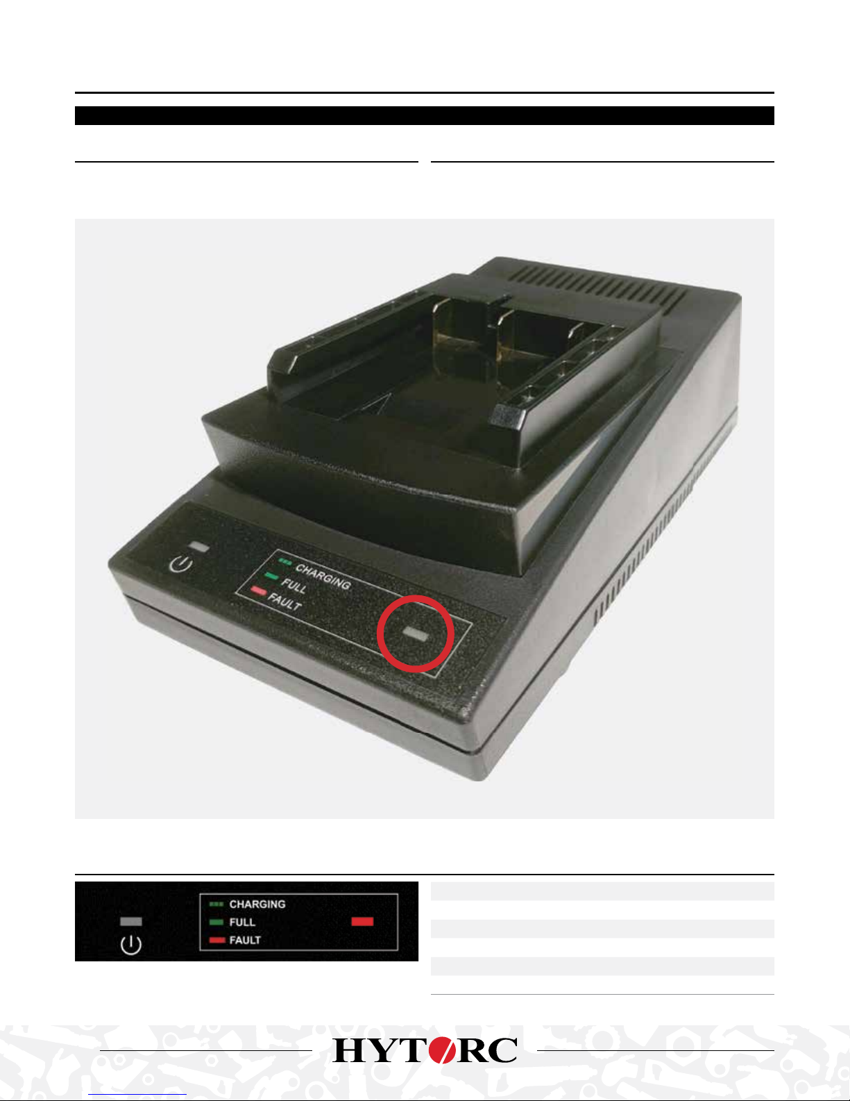
. ADDENDUM IMPORTANT
THIS ADDENDUM SUPERSEDES INFORMATION CONTAINED IN THE PRODUCT MANUAL
WHAT HAS CHANGED? HOW HAS IT CHANGED?
This product contains the new and faster HYTORC U85105 120W
36V/18V Battery Charger.
This new battery charger contains a single combined
Charge Status/Fault LED Indicator, circled below in red.
THE CHARGING/FAULT LED INDICATOR OPERATES AS FOLLOWS:
38
OPERATIONAL STATUS LED INDICATOR
Power O O
Power On / Standby O
Charging Flashing Green
Full Charged Solid Green
Fault or Charge Pending Solid Red


HYTORC WORLD HEADQUARTERS
333 Route 17 N., Mahwah, NJ 07430, +1-201-512-9500
WORLDWIDE HYTORC LOCATIONS
ADVANCED BOLTING SOLUTIONS P. LTD
Navi Mumbai, India, +91-22-4171-4444
HYTORC BRAZIL
Rio de Janeiro, BR, +55-21-2621-1911
HYTORC OF CHINA
Shanghai, +86-21-6254-0813
HYTORC MIDDLE EAST
UAE, +44-7436-549468
HYTORC CENTRAL EUROPE & RUSSIA
Perchtoldsdorf, AU, +43-1-86-51-368
HYTORC JAPAN
Suginami-ku, TYO, +81-3-3314-3315
HYTORC UK
Cramlington, NB, +44-1-670-363800
HYTORC OF KOREA
Kyunggi-Do, +82-31-708-0850
HYTORC AUSTRALIA
Adelaide, South Australia, +61-8-8293-8411
Locate your nearest HYTORC representative or location:
hytorc.com/world • info@hytorc.com • +1-201-512-9500
HYTORC SOUTH AFRICA
Mount Edgecombe, DUR, +27-(0)315023119
HYTORC SINGAPORE
Singapore, +65-689-789-95
HYTORC LATIN AMERICA
Coatzaocoalcos, VER, +52-921-21-52760
CATLITHIUM_SERIESMAN
 Loading...