


Preface
Thanks for your favor in our product. To derive optimum performance from the product, please read
this manual, the corresponding TETRA Terminal Series Feature Book and the Safety Information
Booklet carefully before use.
This manual is applicable to the following model:
Z1p TETRA Portable Terminal
12

Term
Individual Call
Group Call
Half-duplex
Full-duplex
Direct Mode
Operation
(DMO)
13
A half-duplex or full-duplex call
initiat ed by an individual user
to another individual user.
A half-d uple x cal l initiate d by
an individual user to a group.
Half-d uplex communica tion is
also called “two-way alternate
commun icati on”. It indicates
the communication is provided
in both directions, but only one
direction at a time, that is, only
one party is all
or receive at a time.
Fu l l- d up lex com m un ica ti on
is al s o cal led “fu ll- dup l ex
synchronous communication”.
It indicates the communication
is allow ed in bo th dire cti on s
sim ul ta neo us ly, that is, both
p a r ti es c a n tr a ns mi t a nd
receive at the same time.
DM O s upp orts h a lf -du plex
o p e r a ti o n a n d a l lo w s t h e
te rm i nal s t o co m m uni ca t e
directly with each oth
u s in g a T E TR A ne t w or k
infra structure . Thus functio ns
tha t requi re networ k access ,
such as telephone call, will be
unavailable.
owed to transmit
er, without
TM O sup po rts ei th er ha l f duplex or full-duplex operation
a n d a l lo w s t he t e rm i na ls
Trunked
Mode
Operation
(TMO)
to com mun icat e w it h ea ch
other via the TETRA netwo rk
infra structure . Thus functio ns
that require network access are
avail able . To operate in T MO
th e te rmin al mus t be
mo de ,
granted authorization by your
service provider, and must stay
within the network coverage.
Disclaimer
Hytera Commu nic ati ons Co., Ltd. (the Co mpa ny)
e nd e a vo r s t o a ch i e ve t he ac c u ra c y a nd
com ple te nes s of this manual, but no w arr anty of
accuracy or reliability is given. All the specifications
and designs are subject to change without notice due
to cont inuou s tech nology devel opmen t. No par t of
this manual may be copied, modified, translated, or
distributed in any manner without the express wri
permission of us.
We do not gua ran tee, for any partic ula r pur pos e,
th e acc ur ac y, va lidi ty, t i me li nes s, leg iti ma cy or
co m pl ete ne ss of t he Thir d Par ty pr odu ct s a nd
contents involved in this manual.
If you have any suggestions or wo uld like to learn
more details, please visit our website at:
hytera.com
.
tten
http://www.

FCC Statement
This equipment has been tested and found to comply with the limits for a Class B digital
device, pursuant to part 15 of FCC Rules. These limits are designed to provide
reasonable protection against harmful interference in a residential installation. This
equipment generates and can radiate radio frequency energy and, if not installed and
used in accordance with the instructions, may cause harmful interference to radio
communications. However, there is no guarantee that interference will not occur in a
particular installation. If this equipment does cause harmful interference to radio or
television reception, which can be determined by turning the equipment off and on, the
user is encouraged to try to correct.
The interference by one or more of the following measures:
● Reorient or relocate the receiving antenna. Increase the separation between the
equipment and receiver.
● Connect the equipment into an outlet on a circuit different from that to which the
receiver is connected.
● Consult the dealer or an experienced radio/TV technician for help
Operation is subject to the following two conditions: 1. This device may not cause harmful
interference, and 2. This device must accept any interference received, including
interference that may cause undesired operation.
Note:” Changes or modifications to this unit not expressly approved by the party
responsible for compliance could void the user’s authority to operate the equipment.”
Compliance with RF Exposure Standards
Hytera’s TETRA Terminal complies with the following RF energy exposure standards and
guidelines:
• United States Federal Communications Commission, Code of Federal Regulations; 47
CFR § 1.1307, 1.1310 and 2.1093
• American National Standards Institute (ANSI) / Institute of Electrical and Electronic
Engineers (IEEE) C95. 1:2005; Canada RSS102 Issue 5 March 2015.
• Institute of Electrical and Electronic Engineers (IEEE) C95.1:2005 Edition
RF Exposure Compliance and Control Guidelines and
Operating Instructions
To control your exposure and ensure compliance with the occupational/controlled
environment exposure limits always adhere to the following procedures.
Guidelines:
• Do not remove the RF Exposure Label from the device.
• User awareness instructions should accompany device when transferred to other users.
• Do not use this device if the operational requirements described herein are not met.
Operating Instructions:
• Transmit no more than the rated duty factor of 50% of the time. To transmit (talk), push
the Push-To-Talk (PTT) button. To receive calls, release the PTT button. Transmitting
50 % of the time, or less, is important because this radio generates measurable RF
energy exposure only when transmitting (in terms of measuring for standards
compliance).
• Hold the radio in a vertical position in front of face with the microphone (and the other
parts of the radio, including the antenna) at least one inch (2.5 cm) away from the nose.
Keeping the radio at the proper distance is important because RF exposures decrease
with distance from the antenna. Antenna should be kept away from eyes.
• When worn on the body, always place the radio in a Hytera’s approved clip, holder,
holster, case, or body harness for this product. Using approved body-worn accessories is
important because the use of Hytera’s or other manufacturer’s non-approved accessories
may result in exposure levels, which exceed the FCC’s occupational/controlled
environment RF exposure limits.
• Use only manufacturer’s name approved supplied or replacement antennas, batteries,
and accessories. Use of non-manufactur
accessories may exceed the FCC RF exposure guidelines.
•For a list of Hytera’s approved accessories (see the user manual), or (visit the following
website which lists approved accessories: http: add website address), or(The
manufacturer should include the appropriate bracketed item{s} in the manual.)
• For a list of Hytera’s approved accessories (see the user manual), or (visit the following
website which lists approved accessories: www.hytera.cn
IC statement
The device has been tested and compliance with SAR limits, users can obtain Canadian
information on RF exposure and compliance
Après examen de ce matériel aux conformité aux limites DAS et/ou aux limites d’intensité
de champ RF, les utilisateurs peuvent sur l’exposition aux radiofréquences et la
conformité and compliance d’acquérir les informations correspondantes
This device complies with Industry Canada licence-exempt RSS standard(s). Operation is subject to the
following two conditions:
(1) this device may not cause interference, and
(2) this device must accept any interference, including interference that may cause undesired operation
of the device.
Le présent appareil est conforme aux CNR d'Industrie Canada applicables aux
appareils radio exempts de licence. L'exploitation est autorisée aux deux conditions
suivantes : (1) l'appareil ne
doit pas produire de brouillage, et (2) l'utilisateur de l'appareil doit accepter tout
brouillage radioélectrique subi, même si le brouillage est susceptible d'en
compromettre le fonctionnement
er-name approved antennas, batteries, and
14
Contents
Contents---------------------------------------------------------------------1
Items in the Package-----------------------------------------------------2
Product Overview ---------------------------------------------------------2
Product Controls-----------------------------------------------------2
Programmable Keys -----------------------------------------------2
Before Use -----------------------------------------------------------------2
Charging the Battery -----------------------------------------------2
Attaching the Accessories ----------------------------------------3
Status Indication ----------------------------------------------------------4
Status Icon ------------------------------------------------------------4
LED Indicator ---------------------------------------------------------4
Menu Navigation ---------------------------------------------------------5
TMO Menu ------------------------------------------------------------5
DMO Menu------------------------------------------------------------5
Basic Operations ---------------------------------------------------------6
Turning On/Off -------------------------------------------------------6
Switching Operation Mode ----------------------------------------6
Adjusting the Call Volume -----------------------------------------6
Inputting through Keypad -----------------------------------------6
Locking/Unlocking the Keypad ----------------------------------6
PIN Code Security and Changing ------------------------------6
1
Managing the Contacts -------------------------------------------6
Using BT Device ----------------------------------------------------7
Enabling/Disabling Covert Mode -------------------------------7
Call Services ---------------------------------------------------------------8
TMO -------------------------------------------------------------------8
DMO -------------------------------------------------------------------9
Status Message -----------------------------------------------------9
User Message -------------------------------------------------------10
Troubleshooting ----------------------------------------------------------11
Care and Cleaning -------------------------------------------------------13
Product Care ---------------------------------------------------------13
Product Cleaning ----------------------------------------------------13
Optional Accessories ----------------------------------------------------13
Power Supply --------------------------------------------------------13
Audio Accessory ----------------------------------------------------13
Others ------------------------------------------------------------------13
Appendix --------------------------------------------------------------------14
SSI&TSI Dialing Rules --------------------------------------------14
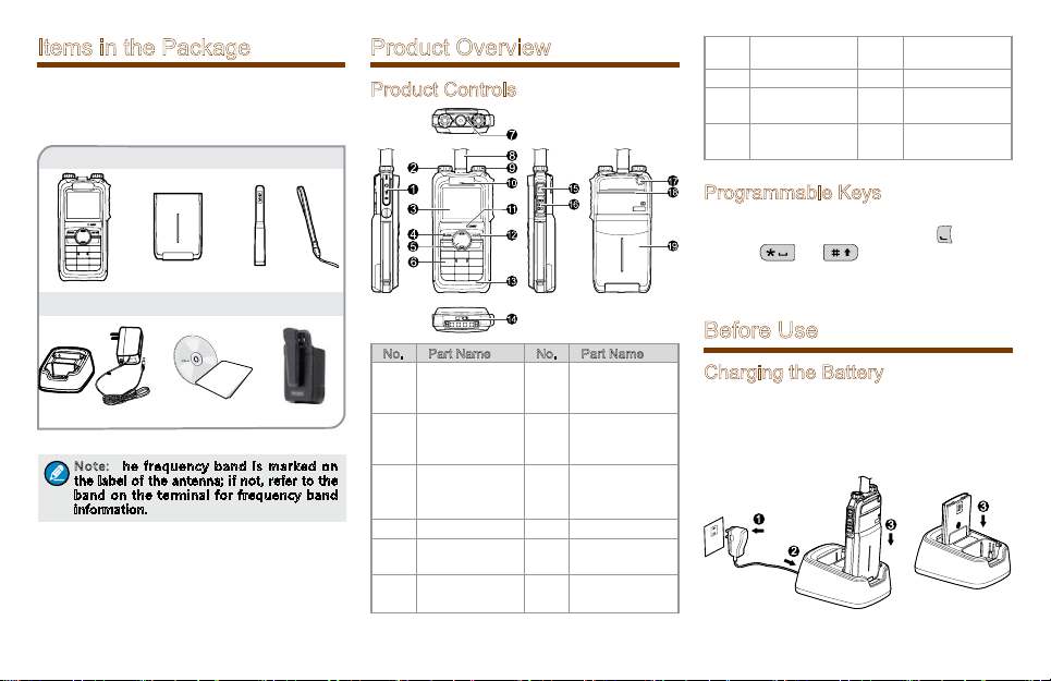
Items in the Package
Ple ase unpack carefu lly and chec k that all ite ms
listed below ar e received. If any item is mi ssing or
damaged, please contact your dealer.
Portable Terminal Battery Antenna Strap
Charger Power Adapter Documentation Kit
OWNER'S MANUAL
Note: T he frequency band is marked on
the label of the an tenna; if not, refer to th e
band on th e termi nal for f reque ncy ba nd
information.
Belt Clip
Product Overview
Product Controls
No. Part Name No. Part Name
Accessory
1
Connector
Power On-
2
Off/Volume
Control Knob
3 LCD Display 13
4 Func/OK Key 14 Battery Latch
Navigation
5
Key
Numeric
6
Keypad
11
12
15
16
Halfduplex Call
Microphone
Options/Back
Key
Fullduplex call
Microphone
Mode Switch/
Hand-free Key
PTT (Push-ToTalk) Key
7 LED Indicator 17
8 Antenna 18 Speaker
Group
9
Selector Knob
Full-duplex
10
Receiver
Emergency
Key
19 Battery
/ /
Programmable Keys
To deriv e enhanced convenience, you can request
your dealer to set t he navigation key,
keys 1-9,
fu nc ti on s an d menu s. For deta il ed i nt ro du ct io n,
please refer to the co rrespon ding TETRA Terminal
Series Feature Book.
and as the shortcuts to needed
, numer ic
Before Use
Charging the Battery
Only use the charger and ba ttery specifi ed by the
Company. The charger LED will indicate the charging
process. The figure below shows you how to charge
the battery.
2
The charger LED indicates you the charging process.
Wh en the cha rg er LED glo ws red , th e char gi ng
begins. When charging is complete, the charger LED
glows green.
The table below shows you the details.
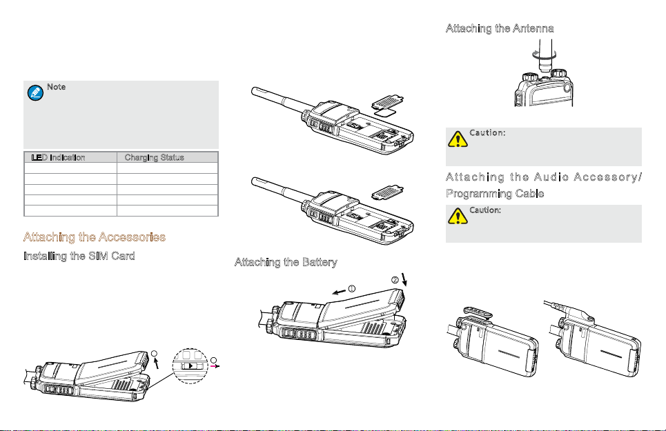
Note
●To achieve optimal battery performance,
please charge the battery for 5 hours
before initial use.
●Please refer to the Safety Information
Booklet for the detailed information on
battery use.
LED Indication Charging Status
Flashes red slowly Standby(no load)
Glows red Charging
Glows orange. 90% charged
Glows green Fully charged
Flashes red rapidly Charging failed
Attaching the Accessories
Installing the SIM Card
If a S I M ca rd is req uire d t o re ali ze the End- to End En cr yp ti on (E2EE) featur e whic h sh ou ld be
purchased separa tely, please install the SIM card
first.
Step 1 Sl id e the ba tt ery la tc h in t he way as th e
arrow shows (see 1), and then lift the battery
from its bottom (see 2).
3
2
Step 2 Loosen the screws fixing the SIM card cover,
op en the cove r, an d then pla ce the card
into the slot properly, as shown in the figure
below.
Step 3 Replace the cover and tighten the screw as
shown in the figure below.
Attaching the Battery
1
1
Attaching the Antenna
Caution: Do not shake the product by
holding the antenna; otherwise the work
performance and lifespan of the antenna
will be lowered.
A t t a c h i n g t h e Au di o A cc es so ry /
Programming Cable
Caution: The audio accessory/programming
cable sh ould be at tach ed prop erly ;
otherwise the waterproof performance of
the pro duct w ill be a ffected.
Step 1 L oo s en t h e s cr ew o n t h e a cc es s or y
connector cover, and uncover the connector.
2
Step 2 Ali gn the acce sso ry plug wit h the produ ct
accessory connector.
Step 3 Secure the accessory plug with screw.

Status Indication
Status Icon
Name Icon Terminal Status
Battery
Strength
Icon
RSSI Icon
Message
Icon
Operation
Mode Icon
Profile
Icons
Accessory
Icon
The battery strength is
low.
More bars indicate more
battery strength.
The terminal has not
registered with the
network (applicable for
TMO only).
More bars indicate a
stronger signal.
Unread message(s).
The Inbox is full.
The terminal is operating
in TMO.
The terminal is operating
in DMO.
The terminal is operating
in fallback mode.
Silent
Normal
Vibration
The audio accessory is
connected.
Name Icon Terminal Status
GPS Icon
BT Icon
Call Icon
Group
Selection
Icon
A GPS module is
connected and the valid
GPS data is received.
Valid GPS data can be
received, and the audio
accessory has been
connected.
A GPS module is
connected and no valid
GPS data is received.
No valid GPS data can
be received, and the
audio accessory has
been connected.
The BT feature is
enabled but the product
is not connected to BT
device.
The product is
connected to BT device.
A call is in progress.
Select a talkgroup.
Name Icon Terminal Status
Gateway
Icon
Repeater
Icon
A gateway device is
available and connected
in DMO.
A gateway device
is available but
unconnected in DMO.
A repeater is available
and connected in DMO.
A repeater is available
but unconnected in
DMO.
LED Indicator
LED Indication Terminal Status
Glows red Transmitting
Glows green Receiving
Fl as hes gree n
slowly
F l a sh es b lu e
slowly
Glows orange. Channel busy in DMO
Channel free in TMO
Channel free in DMO
4

Menu Navigation
The fol lo wing menu list s show the full menu s of
the terminal in TMO and DMO. You can select your
needed menus to be dis played via your dealer. To
select and confirm the options in the menu, operate
as follo ws: in the home screen, you can press the
Func/OK key to enter the “Func” menu, or press
Options/Back key to enter the “Options” menu;
the
then press the
to select the needed menu, finally press the
key. In sections introducing operations, a menu path
is provided for your convenience, e.g. Message ->
Create Msg.
5
Up/Down key on the Navigation key
Func/OK
TMO Menu
DMO Menu

Basic Operations
Turning On/Off
To tu rn on t he terminal, rotate the Power On-Off/
Vol u me Con t ro l kno b cl ock wi se . Th en th e LED
indicator flashes green, and the terminal shows the
power-up screen and sounds power-up alert. Upon
successful powering on, the terminal enters the home
screen. In TMO, after being turned on; the terminal
will register with the network. In DMO, the terminal
will be ready for use after being turned on.
To tu rn off t he termin al, rotat e the
Volume Control knob counter-clockwise until a click
is heard.
Switching Operation Mode
This terminal can operate in either TMO or DMO. To
switch the operation mode, press the
key in the home scre en to e nte r the “Opt ion s”
menu, and then select “TMO” or “DMO”. Or, in
the home screen, press the
Key.
Adjusting the Call Volume
Ro ta te th e Pow er On- O ff /Vo lum e Co ntr ol kno b
clock wise to i ncrease the c all volume, or c ounte rcl oc k w is e t o de c r e ase th e vo l u m e. A f ter th e
adjustment, the ter minal will save the settings and
return to the former screen automatically.
Powe r On-Off /
Options/Back
Mode Switch/Hand-free
Inputting through Keypad
You can use th e n um e ri c key pa d t o enter use r
alias and number, edit messages, etc. The terminal
supports these input methods: English and Number.
To s wit ch the input meth od , pr ess the
on the num er ic keypa d. In E nglis h/N um ber inpu t
me t ho d , you can en te r spe c ia l c ha rac te rs an d
co mm on pun ctua tion s by pr es si ng , ente r
“*” by pre ssi ng
long pressing this key. As for other la nguage input
methods (depending on your customization), operate
accordingly.
an d e nt er a s p ac e b y
ke y
Locking/Unlocking the Keypad
To enable the keypad lock, enter the Function menu
by pres sing the
an d the n go to “S et t in g s - > KP L ock -> On”.
After this feature is enabled, keypad will get locked
autom atica lly when the preset time (pre set by th e
dealer) expires. Then you can press the
then
Apart from locking the keypad via menu, you can lock
the keypad manually by pressing the
and then
Func/O K key in th e home screen,
OK key and
to unlock the keypad.
Func/OK key
directly on the home screen.
PIN Code Security and Changing
PIN code can prevent unidentified user from using
your terminal. To en able or disable the P IN Code
fea ture, ente r th e Fu nct io n me nu from the ho me
screen by pressing the
“Settings -> Security -> PIN Code”. Every time you
need to change the settings, it is required to input the
Func/OK key , and then go to
PIN code first (default PIN code: 1234, preset by the
dealer).
With this feature enabled, you will need to enter the
correct PIN code prior to operating the terminal after
turning it on. If you input the wrong code for 3 times
(predefined by the dealer) in a row, t
be locked. Then you will need to enter the correct
PUK code (default PUK code: 12345678) to reset the
PIN code.
To change the PIN code, go to “Settings -> Security
-> ChangePIN”, and input the correct current PIN
code prior to changing the code.
he terminal will
Managing the Contacts
Contact List
To view the list, press the
Function menu and then go to the “PhoneBook”
menu.
New Contact
To add a ne w contact, you can enter the Function
me nu b y pre ssi n g the
“Pho ne Boo k”. Th en pres s th e
ent er “Opt io ns -> New Con ta ct” to add a ne w
con ta ct : en te r th e co nt act’s ali as in t he edit in g
screen, and press the
No.” screen to inp ut the c ontac t numb er. A t last ,
pr e ss th e
(“Private No.”, “PABX” or “PSTN”).
OK ke y aga in to sel ect the cal l typ e
Viewing the Memory Capacity
To v iew th e me mory capacit y, yo u ca n en te r th e
Func/OK key to enter the
Fu nc/ O K key an d go to
Fun c/ OK key to
OK key to enter the “Input
6

Func menu by pressing the Func/OK key, and go to
“PhoneBook” menu; then press
Func/OK to enter
“Memory”.
Using BT Device
As soon as the product gets successful connection
to the BT device, the audio signal will be transmitted
via the BT device instea d of the mic roph one and
speaker of the product.
Caution:
●To derive the optimum audio quality,
you should use BT devices specified by
The Company: wireless headset, wireless
remote speaker microphone and wireless
finger PTT. For the details, please refer to
Chapter 12. Refer to the corresponding
manual for the detailed operations of the
BT devices.
●If used with other company’s BT
earpiece, the product must connect to
the wireless finger PTT specified by the
Company. Otherwise, the audio will not
be transmitted via the BT earpiece.
Do plac e the product in the way descr ibed below;
otherwise, the audio quality will be lowered.
●When wearing the product, be sure to wear it on
the same side with the BT devices and its LCD
display faces outwards.
●If the product is not with you, be sure that the
distance between it and the BT device is within
10 me te rs and its LCD dis pl ay fac es the BT
device.
You are recommend
BT device in the ways below:
7
ed to connect the product to the
Initial Connection
Step 1 Ena ble the BT feature : pre ss the shor tcut
ke y; or go t o “Fun c - > Ot hers -> BT - >
Sw it ch”. The icon
status bar with the feature enabled.
Note: The BT PT T and the earpiece ar e to b e
connected in th e same way separately. Here
we take how to conne ct the BT PTT as an
example.
Step 2 Turn on the BT device and set it in connection
mod e. Plea se refe r to t he corr es pon di ng
manual for detailed operations.
Step 3 Search for the PTT: go to “Func -> Others
-> BT -> Match -> PTT Search”, the product
will search for the BT PTT.
Step 4 S el ect “St op ” when the pr odu ct has
searched the PTT.
Step 5 Co nne ct to th e BT P TT: g o to “O ptio ns
-> Conn ect”. After getti ng connected, the
pr
oduct LCD display goes from “Connecting
…” to connecte d inte rface with the
the status bar.
wi ll app ea r in the
in
Non-initial Connection
I f a BT de vi ce i s u p t o t h e t w o c on d i ti o ns :
on ce co nne ct ed to and re ser ve d in th e D ev ice
L i s t (u nd e r t h e me nu F u n c -> Ot he r s -> BT
-> Ma t ch ), i t is r ea dy f or c on nec t io n. You can
se l ec t t he BT de vic e fro m t he De vi ce L is t a nd
try conne cti ng. If the conne cti ng is f ail ed, pleas e
do the o pe r at i on s s ta ted in I ni t ia l C on nec ti on.
Moreover, if the product powers off without the BT
atu re dis abled , the BT feat ur e wi ll be en ab le d
fe
automatically upon the product power-on next time.
And if the once connected BT device is powered on,
it will automatically connect to the product.
Note: T he Device List will b e u pdated a s
long as yo u perfor m “PT T Search” or “EP
Search”.
Enabling/Disabling Covert Mode
The covert mode is applied t o conceal the product
from being discovered. When the product is in covert
mode, there will be no audible or visible indication,
such as no indicators or no LCD backlight, and the
ter min al will enter sile nt mode or v ibrat ion mode
(which is preset by the dealer).
Note: If t he product in cove rt mode h as
been connec ted to an audio accessor y, the
audio signal can only be transmitted via the
audio ac cesso ry.
●Enable the covert mode: press the
shortcut key, or go to “ Func -> Settings
-> CovertMode”.
●Disable the covert mode: first press Func/
OK key and then press
.

Call Services
TMO
Individual Call
In TMO mode, an individual call can be initiated either
as a half-duplex call or full-duplex call, which can be
received without pressing any key (Direct Signaling)
or by pressing
your dealer for such programm ing as well as more
details.
Initiating an Individual Call
●Via Menu
In the home screen, press Func/OK key to enter
the “PhoneBook” or “Call Log” submen u,
and select a contact. Then press PTT to initiate
a half -dupl ex call, or press
duplex call.
●Via Manual Dial
In the home scr ee n, to in itia te a h al f-d up le x
ind iv id ua l ca ll , in pu t th e numbe r you wa nt to
cal l thr oug h the key pad , and then press PTT.
To initia te a full-duplex individual call, input the
num be r yo u wa nt to c al l th rou gh the keypa d,
and press
“Private No.”. Then press
duplex call.
Note:
or PTT (Hook Signaling). Contact
to ini tiate a f ull-
repeatedly to select the call type
●Entry of individual numbers must comply
with the SSI&TSI dialing rules. See
“SSI&TSI Dialing Rules” in “Appendix”
for more details.
●Calls will end automatically if the
predefined call timer expires.
to initiate a full-
Answering an Individual Call
●Half-duplex Individual Call
»If it is an incoming call with Direct Signaling,
there will be an alert tone to inform the called
party that a call is received.
»If it is an incoming call with Hook Signaling,
th e te rm in al sou nd s aler t an d vi br at es to
in for m t he cal led pa rty th a t ther e i s a n
incoming call. And to receive the call, the
or
Func/OK key should be pressed.
To take the talk rights d uring the ca ll, there
are two situations:
1) If you h ave no pr e-emp tive priorit y, h old
down
PTT to talk after the talking party stops
talking and releases its
2) If you have already been programmed with
pre-emptive priority, hold down
any time.
●Full-duplex Individual Call
»If it is an incoming call with Direct Signaling,
there will be an alert tone to inform the called
party that a call is received.
»If it is an incoming call with Hook Signaling,
th e te rm in al sou nd s aler t an d vi br at es to
in for m t he cal led pa rty th a t ther e i s a n
incoming call. And to receive the call, the PTT,
Func/OK key or
After the call is established, both parties can talk
at any time, with no need to use any key.
PTT;
should be pressed.
Hanging up/ Rejecting an Individual Call
W h en in i ti at in g t h e in di v i d ua l c a l l, p r e ss
t h e
O p t i o n s / B a c k k e y or t o te rm in a t e it .
In the pr es enc e of an inc omi ng ind ivi du a l c al l,
PTT
PTT to talk at
pr ess th e
In the process of an individua l call , any party can
press
Op tio n s/ Bac k k e y or to re j ec t i t.
to terminate it.
Group Call
Initiating a Group Call
In the home scr een , you can initi ate a g rou p call
to the default group by pres sing
groups, please do as follows:
Step 1 In the h ome screen, rotate the Group Call
Se le ct or kn ob to sele ct a g roup . Plea se
perform this step as soon as the icon
appears; otherwise, you may fail to select.
Step 2 Pr ess the Fu nc / OK key to con fir m you r
selection.
Step 3 Pr es s PTT to initiat e a gr ou p ca ll to th is
group.
Answering a Group Call
You can receive a group call without any operation.
To take the talk rights during the call, there are two
situations:
1) if you hav e no pr e-emp tiv e pri ority, hold do wn
PTT to talk after the talking party stops talking and
releases its
2) if you have already been pro grammed with preemptive priority, hold down
PTT;
Hanging up a Group Call
The callin g party can pr ess to exit a group call.
And for the called parties in a group call, only those
enabled with “Hang Up” feature (programmable by
the dealer) can press
PTT. To cal l other
PTT to talk at any time.
to exit a group call. )
8

Telephone Call
The telephone call is a full-duplex individual call with
Hook signaling . To initiate the call, follow the steps
below. To answer or hang up/reject the call; see the
“Individual Call” in “TMO”.
Initiating a Telephone Call
Step 1 Se lect a g atew ay. O n th e hom e scr ee n,
press Options/Back key to enter the “PSTN
GA T E” or “PA B X GAT E” s u bme nu .
Sele ct an ap prop riat e gat eway, and pres s
Func/OK key to confirm.
Step 2 In pu t a tele ph on e nu mb er. Retu rn to th e
hom e s c r e e n . In pu t a PAB X o r PS TN
nu m be r, w hic h is c om pos ed of a pre fix
(spe cif ied by the gatewa y, please contac t
the system administrator) and
number of the target contact.
Step 3 Select a call type. Select “PABX” or “PSTN”
through the Func/OK key with a screen-label
Step 4 Press
.
to initiate the call.
the telephone
Emergency Call
Initiating an Emergency Call
P re s s t h e
in it i a te an em er ge nc y ca ll to th e pre de f i ned
co nt act. A ny in divid ua l con ta ct, gro up con t ac t,
d e f au l t gr ou p , PS T N or PA BX co nt ac t ca n
b e p re de fi ne d as t h e em er ge nc y co n ta ct .
There are two levels for emergency call: emergency
pri or it y an d pr e-emp ti ve prio rity 3, wh ic h ca n be
9
E me r g e nc y k ey a nd yo u c an
programmed by your dealer. The emergency priority
is endow ed with the high er priv ile ge ; th us a c all
wi th suc h prio rity can bre ak any oth er c all w it h
pre- emp tiv e pri ori ty 3, as well as c alls wit h low er
priorities.
Answering an Emergency Call
The emergency call is always received automatically.
During an emergency call, the calling party can talk
wit h no n eed to us e an y key. I f anoth er memb er
need s to talk, he/she should hold down
after the calling party stops talking and releases its
PTT.
PTT only
Hanging up a Emergency Call
See the corresponding part of “Individual call” or
“Group call” in accordance with the call type of the
predefined contact.
DMO
Individual Call
In DMO mode, an individual call can be initiated only
as a half-duplex call.
Initiating an Individual Call
In the home screen, directly input the number you
want to call thro ugh the keypad, or press
key to en te r th e “Ph on eB oo k” or “Call Log”
submenu, and select a contact. Then press
initiate the call.
Note: Entry of in divid ual numb ers mus t
comply with the SSI&TSI dialing rules. See
“SSI&TSI Dialing Rules” in “Appendix”
for more details.
Func/OK
PTT to
Answering an Individual Call
Yo u c an r e c ei v e a n i nd i vi du a l c al l i n D M O
auto mati call y. Duri ng the c all, you can hol d dow n
PTT to talk after the initiating party stops talking and
releases its
PTT.
Hanging up an Individual Call
The calling party can press
And the called party can press
to terminate the call.
to exit the call.
Group Call
Group calls in DMO mode is the same as that in TMO
mode. Please refer to operation method described in
“Group Call” in the above “TMO” section.
Emergency Call
In DMO mode, emerg ency calls are endowed with
emergency priori ty only. Please refer to o pera tion
me th od de scr ib ed in”E m er gen cy Ca ll” in the
above “TMO” section.
Status Message
Status message, which shou ld be prog rammed by
your dealer only, can facilitate instant messaging of
the frequently-used messages. You can only send
or view rather than edit the status messages. When
the messa ge is sent su ccessful ly, fo r the receiving
term ina l, it wi ll receiv e eit her the sta tus ID of the
status message (if the terminal has no t predefi ned
the message text) or the prede
ID (if the terminal has predefined the message text).
fined text of the status

Note: Th e Se nd St atusMsg function and the
statu s mess age are prede fine d by the d ealer
via the CPS.
Sending a Status Message
●Press the
●Long press the programmed
Func/OK key and go to “Message ->
Create Msg -> StatusMsg -> Sel Msg”. Select a
desired status message, and press the
key to proceed. Choose either an individual or a
group as the target contact, input the appropriate
number and press
to send the preset status message directly.
Func/OK to send the message.
Send StatusMsg key
Func/OK
Viewing the Status Message
Wh en the ico n
ind ica te s there is/a re unrea d me ssa ge(s) . Do as
follows to view it:
●In the p rom pt screen for an unread messa ge,
press the
press
Func/OK key again to read.
●In the home screen, press the
navigate to “Message -> Inbox -> Inbox”. Then
you can view the unread message.
ap pe a rs in th e statu s bar, it
Func/OK key to enter the Inbox, and
Func/OK key and
User Message
TMO
Editing a User Message
●Press the
Sending a User Message
●After editing, press
Func/OK key and navigate to “Message
-> Create Msg -> User Msg”. Press
key again to edit a user message.
Func/OK key to confirm. Then
Func/OK
select the target contact and decide whether to
send it as a flash message.
Note: If the message is sent as a flash
message, the receiving party can preview
all the content in a predef ined time period
without any op eration. Once the time period
expires, the ter minal will go bac k to the
forme r s creen, with the icon
on the st atus ba r.
displaying
Viewing the User Message
Wh en the ico n
ind ica te s there is/a re unrea d me ssa ge(s) . Do as
follows to view it:
●In the p rom pt screen for an unread messa ge,
press the
press
Func/OK key again to read.
●In the home screen, press the
navigate to “Message -> Inbox -> Inbox”. Then
you can view the unread message.
ap pe a rs in th e statu s bar, it
Func/OK key to enter the Inbox, and
Func/OK key and
DMO
Editing a User Message
Press the
Func/OK key and navigate to “Message
-> Create Msg -> User Msg”. Press
again to edit a user message.
Sending a User Message
After editing, press
either an individual or a group as the target contact,
input the appropriate number and press
send the message.
Func/OK to confirm. Then choose
Func/OK key
Func/OK to
Viewing the User Message
Operat e in th e s a m e wa y as th at de sc r i b e d
in”Viewing the User Message” in the above “TMO”
section.
10

Troubleshooting
Phenomenon Analysis Solution
Networ k registrati on fails or netw ork
can not be found.
Calls cannot be initiated.
A certain group call can not be initiated
or received.
Calls are always interrupted.
A h a lf - d u
established.
Abnormal disconnection occurs during
a call.
11
p l ex c al l c a n n o t be
The terminal may be operating in DMO. Switch to TMO mode.
The terminal may get out of the network coverage (in TMO
mode).
The terminal may not be granted network access.
Th e te rm in al or the ca ll ed par ty may not be wi th in the
network coverage.
The terminal may operate in an improper mode.
The terminal may not be a member of the group.
The terminal may not be a utho rized to acce ss the target
group.
The current channel is assigned to emergency calls or other
calls with higher priority.
The predefined time period for establishing a call may expire.
The chan nel may be o cc upi ed by ano the r termi nal with
higher call priority.
The channel resources may be allocated to other services
due to overloaded network.
The terminal may get out of the network coverage (in TMO
mode).
Th e te rm in al mig ht ope ra te at an unf av or ab le posit io n
where communication may be blocked by high buildings or
frustrated in the underground areas (in DMO mode).
Check the sig nal strength . Mak e sure the ter minal is
within the network coverage.
C o n t a c t th e n et w o r k op er at o r fo r th e te rm i n a l
authorization.
Check the sig nal strength . Mak e sure the ter minal is
within the network coverage.
Che ck the opera ti on mode. Ma ke sure the te rm ina l
works in the right mode.
Check whether the ter
not, contact your dealer to add the terminal to the group.
C o n t a c t th e n et w o r k op er at o r fo r th e te rm i n a l
authorization.
Wait until the channel becomes available and try again.
Make sure the call is established within the predefined
time period.
Wait until the channel becomes available and try again.
Wait until the channel
Check the sig nal strength . Mak e sure the ter minal is
within the network coverage.
Move to an open
minal is a member of the group. If
becomes available and try again.
and flat area, and restart the terminal.

Phenomenon Analysis Solution
As for the same status message, the
co nt en t disp laye d at t he r ece iv in g
pa rt y i s dif fe r en t fro m tha t of th e
sending party .
The BT device can not connect to the
product.
If the above solutions can not fix your problems, or you may have some other queries, please contact us or your local dealer for more technical support.
The parties have associated the same status message ID
with different contents.
The BT device battery may be low. Charge the BT device.
The distance bet
out of 10 meters.
ween the BT device and the product may be
Make sure the status message ID is associated with the
same content.
Be sure that the distance between the BT device and the
product is within 10 meters.
12

Care and Cleaning
To guarantee optimal performance as well as a long
ser vice life of t he produ ct , pl eas e follo w th e ti ps
below.
Product Care
●Do not pierce or scrape the product.
●Keep the product far away from substances that
can corrode the circuit.
●Do not hol d t he pr o du ct by it s an t en na or
earpiece cable directly.
●Attach the accessory connector cover when the
product is not in use.
Product Cleaning
Caution: Power off the product before
cleaning.
●Clean up the dust and fine particles on
the product surface and charging piece
with a clean and dry lint-free cloth or a
brush regularly.
●Use neutral cleanser and a non-woven
fabric to clean the keys, control knobs
and front case after long-time use. Do
not use chemical preparations such as
stain removers, alcohol, sprays or oil
preparations, so as to avoid surface case
damage.
●Make sure the product is completely dry
before use.
13
Optional Accessories
The following items are the main optional accessories
for the product, and please consult your local dealer
for more other accessories.
Caution: Use the ac cesso ries specifie d by
the Comp any only. If not, we shall not be
liable for any losses or damages arising out
of use of unauthorized a ccessories .
Power Supply
●BL1103 Li-Ion Battery(1100mAh)
●BL1809 Li-Ion Battery(1800mAh)
●CH04L01 Portable Charger
●CHV09 Vehicle Adapter for Charger
●MCA05-X Battery Optimizing System
●MCA10 MCU Multi-unit Rapid-r ate Charger (for
Li-Ion Batteries)
Audio Accessory
●EWN08 Digital Wireless Covert Earpiece
(Flatpack Sensor)
●ESN14 Remote Earbud
●EHN20 Remote Swivel Earset
●EHN21 Remote C-Earset
●EAN22 Detachable Earset with
Transparent Acoustic Tube
●EAN21 3-Wire Surveillance Earpiece with
Transparent Acoustic Tube (Beige)
●EAN24 2-Wire Surveillance Earpiece with
Transparent Acous
●SM26N1 Waterproof Remote Speaker
tic Tube (Black)
Microphone(IP67)
●SM26N2 Waterproof Remote Speaker
Microphone(IP54)
●POA47 Wireless Finger PTT
●EHW02 Wireless Earpiece With Dual-PTT
Others
●PC66 Programming Cable
●NCN009 Covert Shoulder Harness
●PCN005 Belt Clip

Appendix
SSI&TSI Dialing Rules
In the TETRA system, subscribers are distinguished
by diffe rent identities. Each subs criber is assign ed
with a unique short subscribe r identity (SSI), which
serves a part of the TETRA subscriber identity (TSI).
And TSI is genera lly composed in this way: Mobile
Country Code (MCC) + Mobile Network Code (MNC)
+ SSI. To initiate an individual call, please dial the SSI
ompliance with the rules below.
or TSI in c
●SSI Dialing
Make sure there are not more than 8 digits.
●TSI Dialing
»MNC+SSI:
1 ) I n p u t t h e M N C a s i t i s ;
2) SSI must be 8 digits long. Add 0 before the
first digit of SSI which is shorter than 8 digits.
For example, when MNC is 20 and SSI is 504,
you need to input 2000000504.
»M C C + M N C + S S I :
1) MCC must contain 3 digits. Add 0 before the
first digit of MCC
2) MNC must contain 4 or 5 digits. When the
MNC is shorter than 4 digits, add 0 before its
first digit; when it is 5 digits long, use it directly;
3) SSI must be 8 digits long. Add 0 before the
first digit of SSI which is shorter than 8 digits.
F o r ex am p l e , w h e n MC C i s 460 , MN C
is 20 an d S SI is 504, y ou nee d t o i npu t
460002000000504.
which is shorter than 3 digits;
14
 Loading...