

Hytera Communications PT580HPF5 User Manual

Copyright Information
Hytera is the trademark or registered trademark of
Hytera Communications Co., Ltd. (the Company) in
PRC and/or other countries or areas. The Company
retains the ownership of its trademarks and product
names. All other trademarks and/or product names
that may be used in this manual are properties of their
respective owners.
Disclaimer
The Company endeavors to achieve the accuracy
and completeness of this manual, but no warranty of
accuracy or reliability is given. All the specifications
and designs are subject to change without notice due
to continuous technology development. No part of
this manual may be copied, modified, translated, or
distributed in any manner without the express written
permission of us.
We do not guarantee, for any particular purpose, the
accuracy, validity, timeliness, legitimacy or completeness
of the Third Party products and contents involved in this
manual.
If you have any suggestions or would like to learn more
details, please visit our website at: http://www.hytera.
com.
RF Radiation Information
This product must be restricted to operations in an
Occupational/Controlled RF exposure Environments.
Users must be fully aware of the hazards of the
exposure and able to exercise control over their RF
exposure to qualify for the higher exposure limits.
RF Radiation Prole
Radio Frequency (RF) is a frequency of electromagnetic
radiation in the range at which radio signals are
transmitted. RF technology is widely used in
communication, medicine, food processing and other
elds. It may generate radiation during use.
RF Radiation Safety
In order to ensure user health, experts from relevant
industries including science, engineering, medicine and
health work with international organizations to develop
standards for safe exposure to RF radiation. These
standards consist of:
● United States Federal Communications Commission,
Code of Federal Regulations; 47CFR part 2 sub-part
J;
● American National Standards Institute (ANSI)/
Institute of Electrical and Electronic Engineers (IEEE)
C95. 1-1992;
● Institute of Electrical and Electronic Engineers (IEEE)
C95. 1 – 1999;
● International Commission on Non-Ionizing Radiation
Protection (ICNIRP) 1998;
FCC Regulations
Federal Communication Commission (FCC) requires
that all radio communication products should meet the
requirements set forth in the above standards before
they can be marketed in the U.S, .and the manufacturer
shall post a RF label on the product to inform users
of operational instructions, so as to enhance their
occupational health against exposure to RF energy.
Operational Instructions and Training
Guidelines
To ensure optimal performance and compliance with
the occupational/controlled environment RF energy
exposure limits in the above standards and guidelines,
users should transmit no more than 50% of the time and
always adhere to the following procedures:
● Your radio radiates measurable RF energy only
while it is transmitting (during talking), not when it is
receiving (listening) or in standby mode.
● Keep the radio at least 2.5 centimeters away from
your body during transmission.
EU Regulatory Conformance
As certied by the qualied laboratory, the product is in
compliance with the essential requirements and other
relevant provisions of the Directive 1999/5/EC.Please
note that the above information is applicable to EU
countries only.

Contents
Document Conventions -------------------------------------------------------------- 2
Instructional Conventions ------------------------------------------------------ 2
Notational Conventions --------------------------------------------------------- 2
Key Operation --------------------------------------------------------------------- 2
Term Explanation ----------------------------------------------------------------- 2
Item s in the Pac kage ------------------------------------------------------------------ 2
Product Overview ---------------------------------------------------------------------- 3
Product Controls ------------------------------------------------------------------ 3
Programmable Keys ------------------------------------------------------------- 3
Before Use -------------------------------------------------------------------------------- 3
Charging the Battery ------------------------------------------------------------- 3
Assembling the Accessories -------------------------------------------------- 3
Status Indication ----------------------------------------------------------------------- 4
Status Icon -------------------------------------------------------------------------- 4
LED Indicator ----------------------------------------------------------------------- 5
Menu Navigation ------------------------------------------------------------------------ 5
TMO Men u -------------------------------------------------------------------------- 5
DMO Menu -------------------------------------------------------------------------- 5
Basic Operations ----------------------------------------------------------------------- 6
Turning On/Off --------------------------------------------------------------------- 6
Switching Operation Mode ----------------------------------------------------- 6
Adjusting the Call Volume ------------------------------------------------------ 6
Inputting through Keypad ------------------------------------------------------- 6
Locking/Unlocking the Keypad ------------------------------------------------ 6
PIN Code Security and Changing -------------------------------------------- 6
Managing the Contacts---------------------------------------------------------- 6
Call Services ----------------------------------------------------------------------------- 6
TMO ----------------------------------------------------------------------------------- 6
DMO --------------------------------------------------------------------------------- 8
Message ----------------------------------------------------------------------------------- 8
Status Message ------------------------------------------------------------------ 8
User Message --------------------------------------------------------------------- 8
Troubleshooting ------------------------------------------------------------------------ 9
Care and Cleaning ---------------------------------------------------------------------9
Optional Accessories ---------------------------------------------------------------10
Appendix ---------------------------------------------------------------------------------10
SSI&TSI Di aling Rule s ---------------------------------------------------------10
1
Document Conventions
For your better understanding of this manual, please
read the following conventions rst.
Instructional Conventions
Icon Description
Note
Notational Conventions
Convention Description
“ ”
Bold
->
Key Operation
Operation Denition
Short press To press a key and release it quickly.
Long press
Hold To press a key and do not release it.
Indicates references that can further
describe the related topics.
Indicates situations that could cause
Caution
data loss or equipment damage.
The quotation marks enclose the name
of a software interface element. For
example, click “OK”.
The text in boldface denotes the name
of a hardware button. For example,
press the PTT key.
The symbol directs you to access
a multi-level menu. For example, to
select “New” from the “File” menu, we
will describe it as follows: File -> New.
To press a key for the preset time (2s
by default) and release it.
Term Description
Half-duplex communication is also called
Halfduplex
Fullduplex
Direct
Mode
Operation
(DMO)
Trunked
Mode
Operation
(TMO)
“two-way alternate communication”. It
indicates the communication is provided
in both directions, but only one direction
at a time, that is, only one party is allowed
to transmit or receive at a time.
Full-duplex communication is also called
“full-duplex synchronous communication”.
It indicates the communication is allowed
in both directions simultaneously, that is,
both parties can transmit and receive at
the same time.
DMO supports half-duplex operation and
allows the terminals to communicate
directly with each other, without using a
TETRA network infrastructure.
Thus functions that require network
access, such as telephone call, will be
unavailable.
TMO supports either half-duplex or fullduplex operation and allows the terminals
to communicate with each other via the
TETRA network. Thus functions that
require network access are available. To
operate in TMO mode, the terminal must
be granted authorization by your service
provider, and must stay within the network
coverage.
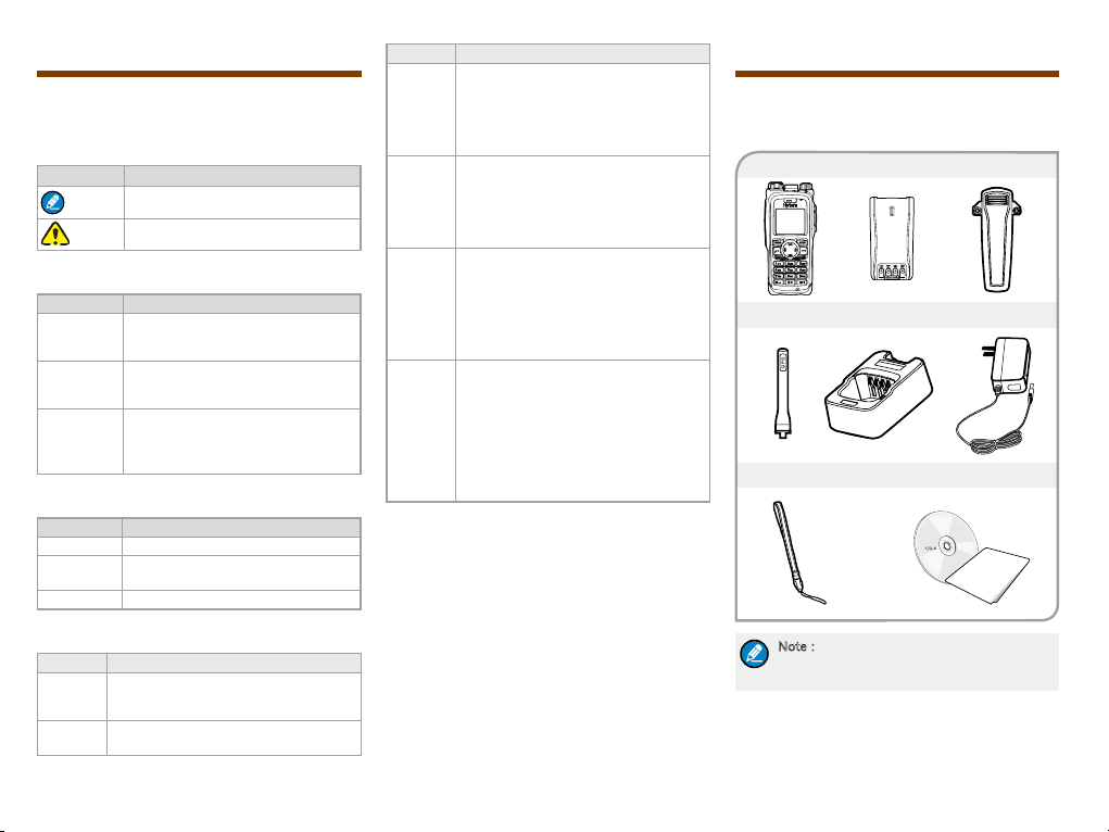
Items in the Package
Please unpack carefully and check that all items listed
below are received. If any item is missing or damaged,
please contact your dealer.
Portable Terminal Battery Belt clip
Antenna Charger Power Adapter
Strap Documentation Kit
OWNER'S MANUAL
Term Explanation
Term Description
Individual
Call
Group
Call
2
A half-duplex or full-duplex call initiated
by an individual user to another individual
user.
A half-duplex call initiated by an individual
user to a group.
Note:The frequency band is marked on the
label of antenna; if not, refer to the label on
the terminal for frequency band information.
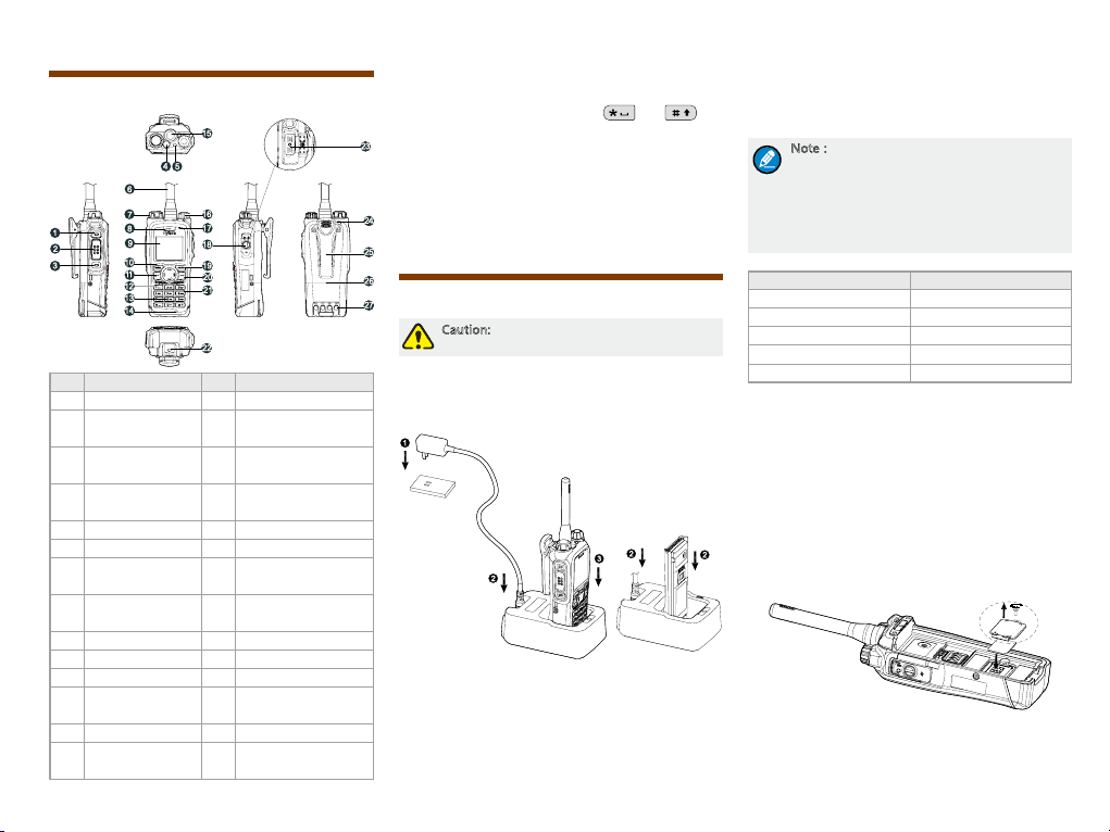
Product Overview
Product Controls
No. Part Name No. Part Name
1 SK1 (Side Key 1) 15 Antenna Connector
PTT (Push-to-talk)
2
Key
3 SK2 (Side Key 2) 17
4 Emergency Key 18
5 LED Indicator 19 Options/Back Key
6 Antenna 20 End Key
Group Selector
7
Knob
Full-duplex
8
Receiver
9 LCD Display 23 Accessory Contact
10 Func/OK Key 24 Strap Hole
11 Answer/Call Key 25 Belt Clip
Half-duplex
12
Speaker
13 Numeric Keypad 27 Charging Piece
Full-duplex
14
Microphone
Power On-Off/Volume
16
Control Knob
Half-duplex
Microphone
Accessory Contact
Cover
21 Navigation Key
22 Battery Latch
26 Battery
Programmable Keys
For enhanced convenience, you can request your
dealer to program the keys (SKI, SK2, navigation key,
answer/call key, numeric keys 1-9, and ) as
the shortcuts to needed menus and functions. For the
detailed introduction, please read the corresponding
TETRA Terminal Series Feature Book.
Before Use
Charging the Battery
Caution: Make sure the radio is powered off
during charging.
Only use the charger and battery specified by the
Company. The charger LED indicator will indicate the
charging process. See the figure below showing the
steps for charging.
1. Connect the power adapter to AC socket. See arrow
.
①
2. Plug the other end of the power adapter into the rear
jack of charger. See arrow ②.
3. Place the terminal with the battery attached, or the
battery alone, into the charger. See arrow ③.
During charging, the LED indicator on the charger will
indicate the charging status. The charging begins when
the charger LED glows red. When charging is complete,
the charger LED glows green.
See the following table for details.
Note:
●To achieve optimal battery performance,
please charge the battery for 5 hours
before initial use.
●Be sure to read the Safety Information
Booklet, to get necessary safety
information.
LED Indication Charging Status
Flashes red slowly Standby(no load)
Glows red Charging
Glows orange 90% charged
Glows green Fully charged
Flashes red rapidly Failure
Assembling the Accessories
Installing the SIM card
If a SIM card is required to realize the End-to-End
Encryption (E2EE) feature which should be purchased
separately, please install the SIM card rst.
1. Turn off the terminal, and then slide the battery latch
upwards to unlock the battery.
2. Loosen the screw xing the SIM card cover, remove
the cover, and then place the card in the holder
properly as shown below.
3. Replace the cover and tighten the screw as shown
below.
3
 Loading...