


User Manual

Copyright Information
Hytera is the trademark or registered trademark of Hytera Communications Corporation Limited (the
Company) in PRC and/or other countries or areas. The Company retains the ownership of its trademarks
and product names. All other trademarks and/or product names that may be used in this manual are
properties of their respective owners.
The product described in this manual may include the Company’s computer programs stored in memory or
other media. Laws in PRC and/or other countries or areas protect the exclusive rights of the Company with
respect to its computer programs. The purchase of this product shall not be deemed to grant, either directly
or by implication, any rights to the purchaser regarding the Company’s computer programs. Any of the
Company’s computer programs may not be copied, modified, distributed, decompiled, or
reverse-engineered in any manner without the prior written consent of the Company.
Disclaimer
The Company endeavors to achieve the accuracy and completeness of this manual, but no warranty of
accuracy or reliability is given. All the specifications and designs are subject to change without notice due
to continuous technology development. No part of this manual may be copied, modified, translated, or
distributed in any manner without the express written permission of us.
We do not guarantee, for any particular purpose, the accuracy, validity, timeliness, legitimacy or
completeness of the Third Party products and contents involved in this manual.
If you have any suggestions or would like to learn more details, please visit our website at:
http://www.hytera.com.

FCC Statement
This is A 90.219 CLASS A DEVICE.
This equipment has been tested and found to comply with the limits for a Class B digital device, pursuant
to part 15 of FCC Rules. These limits are designed to provide reasonable protection against harmful
interference in a residential installation. This equipment generates and can radiate radio frequency
energy. If not installed and used in accordance with the instructions, it may cause harmful interference to
radio communications. However, there is no guarantee that interference will not occur in a particular
installation. Verification of harmful interference by this equipment to radio or television reception can be
determined by turning it off and then on. The user is encouraged to try to correct the interference by one
or more of the following measures:
Reorient or relocate the receiving antenna. Increase the separation between the equipment and
receiver.
Connect the equipment into an outlet on a different circuit to that of the receiver's outlet.
Consult the dealer or an experienced radio/TV technician for help.
Operation is subject to the following two conditions:
This device may not cause harmful interference.
This device must accept any interference rece
ived, including interference that may cause undesired
operation.
Note: Changes or modifications to this unit not expressly approved by the party responsible for
compliance could void the user's authority to operate the equipment.
WARNING:
This is NOT a CONSUMER device. It is designed for installation by FCC LICENSEES and QUALIFIED INSTALLERS.
You MUST have an FCC LICENSE or express consent of an FCC Licensee to operate this device.
You MUST register Class B signal boosters (as defined in 47 CFR 90.219) online at
www.fcc.gov/signal-boosters/registration.
Unauthorized use may result in significant forfeiture penalties,
including penalties in excess of $100,000 for each continuing violation.”
Operational Instructions and Training Guidelines
To ensure optimal performance and compliance with
exposure limits in the above standards and guidelines,
Antenna gain must not exceed 2dBi.
The antenna must be installed complying with the requirements of manufacturer or supplier, and it
must be at least 0.65 meters away from human body.
the general/Uncontrolled environment RF energy
users should
always adhere to the following procedures:

Compliance with RF Exposure Standards
Hytera's radio complies with the following RF energy exposure standards and guidelines:
United States Federal Communications Commission, Code of Federal Regulations; 47 CFR §
1.1307, 1.1310 and 2.1091
American National Standards Institute (ANSI) / Institute of Electrical and Electronic Engineers (IEEE)
C95. 1:2005; Canada RSS102 Issue 5 March 2015
Institute of Electrical and Electronic Engineers (IEEE) C95.1:2005 Edition
ISEDC Statement
This device complies with Innovation, Science and Economic Development Canada Compliance
license-exempt RSS standard(s). Operation is subject to the following two conditions:
This device may not cause harmful interference.
This device must accept any interference received, including interference that may cause undesired
operation.
Le présent appareil est conforme aux CNR d'Industrie Canada applicables aux appareils radio exempts
de licence. L'exploitation est autorisée aux deux conditions suivantes: (1) l'appareil ne doit pas produire
de brouillage, et (2) l'utilisateur de l'appareil doit accepter tout brouillage radioélectrique subi, même si le
brouillage est susceptible d'en compromettre le fonctionnement.
ISEDC Radiation Exposure Statement:
This device must be restricted to work relate
d operations in an
General/Uncontrolled RF
exposure Environment.
This equipment should be installed and operated with minimum di
stance 65cm between the
antenna & your body.
ISEDC exposition aux radiations:
Ce dispositif doit être limité aux opérations liées au travail dans un environnement
d'exposition RF
Cet équipement doit être installé et utilisé avec un minimum ance entre le
général/Incontrôlée.
de 65cm de dist
antenne et votre corps.
WARNING:
This is NOT a CONSUMER device. It is designed for installation by an installer approved by an ISED licensee.
You MUST have an ISED LICENCE or the express consent of an ISED licensee to operate this device.

User Manual Contents
Contents
Documentation Information ..................................................................................................................... 1
1. Introduction ........................................................................................................................................... 3
1.1 Product Description ........................................................................................................................... 3
1.2 Highlights ........................................................................................................................................... 3
1.3 System Architecture ........................................................................................................................... 3
1.3.1 Star Topology ........................................................................................................................... 4
1.3.2 Chain Topology ........................................................................................................................ 5
1.3.3 Ring Topology .......................................................................................................................... 5
1.3.4 Hybrid Topology ....................................................................................................................... 6
1.4 Specifications .................................................................................................................................... 6
2. Packing List ......................................................................................................................................... 10
2.1 Cable-access Donor Unit ................................................................................................................. 10
2.2 Wireless-access Donor Unit ............................................................................................................ 10
2.3 Remote Unit ..................................................................................................................................... 10
3. Getting Started .................................................................................................................................... 11
3.1 Appearance ..................................................................................................................................... 11
3.2 Donor Unit Interfaces ....................................................................................................................... 12
3.2.1 Cable-access Donor Unit ....................................................................................................... 12
3.2.2 Wireless-access Donor Unit .................................................................................................. 13
3.3 Remote Unit Interfaces .................................................................................................................... 13
3.4 Interface Description ........................................................................................................................ 14
3.5 Interface Definition ........................................................................................................................... 15
3.6 LED Indicators ............................................................................................................
4. Installation ........................................................................................................................................... 18
4.1 Safety Information ............................................................................................................................ 18
4.2 Installation Flow ............................................................................................................................... 19
4.3 Preparation ...................................................................................................................................... 19
4.3.1 Environment .......................................................................................................................... 20
4.3.2 Instruments and Tools ............................................................................................................ 21
4.3.3 Material Preparation .............................................................................................................. 21
..................... 16
4.4 Installing the Units ........................................................................................................................... 21
4.4.1 Installation Parts .................................................................................................................... 22
4.4.2 Installing the Product ............................................................................................................. 22
4.4.3 Cabling .................................................................................................................................. 27
4.5 Post-installation Check .................................................................................................................... 34
4.5.1 Checking the Installation........................................................................................................ 34
4.5.2 Checking the Device with Power On ..................................................................................... 34
i

Contents User Manual
5. Power On and Power Off .................................................................................................................... 36
5.1 Powering On .................................................................................................................................... 36
5.2 Powering Off .................................................................................................................................... 36
6. Debugging ........................................................................................................................................... 37
6.1 Preparation ...................................................................................................................................... 37
6.2 Procedure ........................................................................................................................................ 37
6.2.1 Querying Parameters ............................................................................................................ 39
6.2.2 Setting Parameters ................................................................................................................ 39
6.2.3 Upgrade ................................................................................................................................. 41
6.2.4 Exporting the Logs ................................................................................................................. 42
7. System Maintenance ........................................................................................................................... 43
7.1 Care and Cleaning ........................................................................................................................... 43
7.2 Routine Maintenance ....................................................................................................................... 43
7.3 Alarm Handling ................................................................................................................................ 44
7.4 Troubleshooting ............................................................................................................................... 45
8. Appendix: Parameters ........................................................................................................................ 46
ii
User Manual Documentation Information
Documentation Information
This section describes the audiences, conventions and revision history of this document.
Intended Audience
This document is intended to be read by:
Sales engineers
Common users
Documentation Conventions
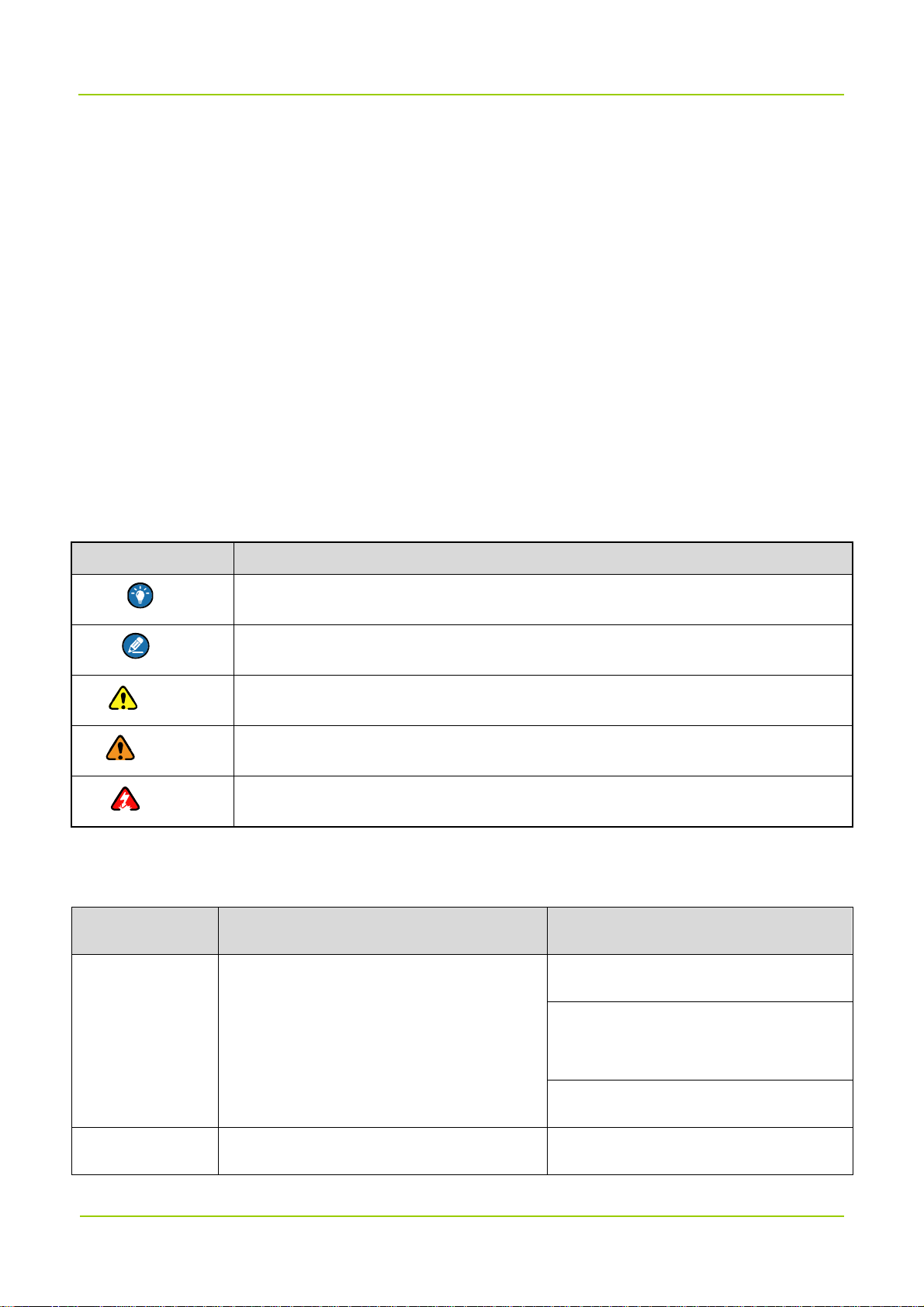
Icon Conventions
Icon Description
Tip Indicates information that can help you make better use of your product.
Note Indicates references that can further describe the related topics.
Caution Indicates situations that could cause data loss or equipment damage.
Warning Indicates situations that could cause minor personal injury.
Danger Indicates situations that could cause major personal injury or even death.
Notation Conventions
Item Description Example
To save the configuration, click Apply.
Boldface
" "
Denotes menus, tabs, parameter names,
window names, dialogue names, and
hardware buttons.
Denotes messages, directories, file names,
1
The Log Level Settings dialogue
appears.
Press the PTT key.
The screen displays "Invalid!"
Documentation Information User Manual
Item Description Example
> Directs you to access a multi-level menu. Go to File > New.
Italic Denotes document titles.
Courier New
folder names, and parameter values.
Denotes commands and their execution
results.
Open "PDT_PSS.exe".
Go to "D:/opt/local".
In the Port text box, enter "22".
For details about using the DWS, refer
to Dispatch Workstation User Guide.
To set the IP address, run the following
command:
vos-cmd - m name IP
Revision History
Document Version Product Version Release Date Description
Added descriptions on digital repeaters
of low configuration.
03 V1.0 August 2018
Added detail steps in “Setting
Parameters”.
Added contents on the wireless-access donor
02 V1.0 May 2018
01 V1.0 March 2018 Modified the names of several devices.
00 V1.0 January 2018 Initial release.
unit and band-selective repeater.
2

User Manual Introduction
1. Introduction
1.1
DS-9300 Digital Repeater ("DS-9300") is the new generation of repeater developed by Hytera. Using
optical fibers to transmit signal, DS-9300 effectively makes up for the signal decline between base stations
(BSs) and radios.
Featuring low transmission loss and easy wiring, DS-9300 delivers long distance transmission of
multicarrier signals and strong and dynamic signal coverage. It is an ideal solution to blind zones such as
populated urban areas, large exhibition halls, stadiums, campuses, tunnels, metro stations and etc.
DS-9300 has two types of configurations, including low configuration and high configuration, which have
the same appearance but different features.
1.2
DS-9300 has the following highlights:
Flexible monitoring
Product Description
Highlights
DS-9300 provides remote monitoring (through IP network) and local monitoring (through RS232 serial
port). Users can manage all devices through the network management system, or remotely query,
configure and upgrade a single device.
Excellent hardware performance
DS-9300 has low intermodulation noise, strong out-of-band rejection, low interference and great
interference resistance.
Software-Defined Radio (SDR) Technology
DS-9300 achieves uplink squelch, delay compensation, carrier rejection, digital multi-carrier and etc
with the SDR Technology. It supports multiple network topologies such as star, chain, ring and hybrid
topologies.
Effective mechanical design
DS-9300 is compact and portable with effective heat dissipation and resistance to water, dust and salt
spray. Various installation methods are available for DS-9300 including wall-mounting, pole-mounting
and etc.
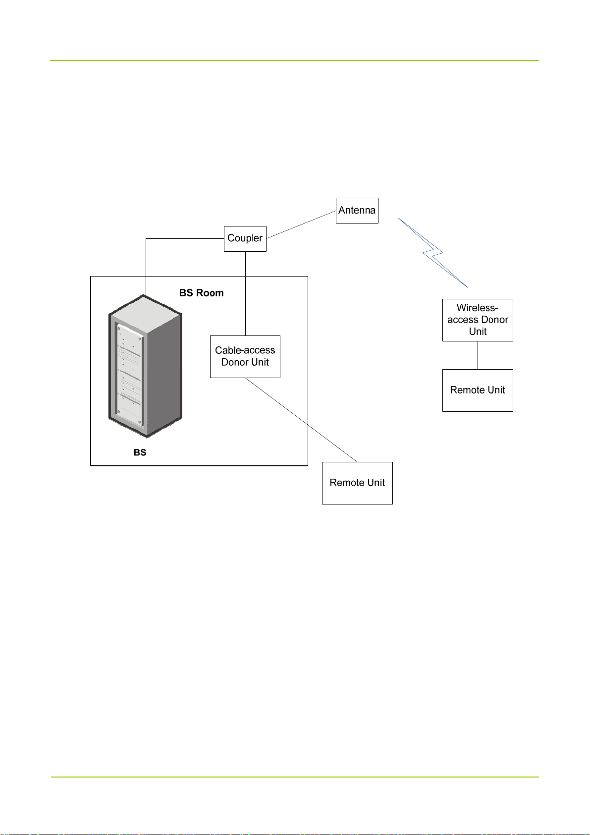
1.3
DS-9300 consists of the donor unit and the remote unit. They transparently convey and amplify the
System Architecture
3
Introduction User Manual
wireless signal between the BS and the radios. Donor unit includes the cable-access donor unit and the
wireless-access donor unit. The cable-access donor unit is mounted into a 19-inch rack at the BS location
while the wireless-access donor unit can be installed remotely from the BS. The remote unit is installed
away from the donor unit over a fiber link. The following figure shows the networking of DS-9300 and the
BS.
Various topologies are available for networking between the donor and the remote units, including star,
chain, ring and hybrid topologies.
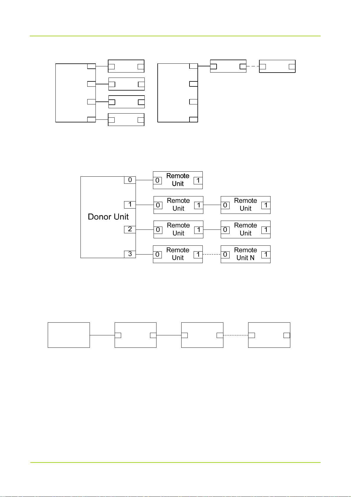
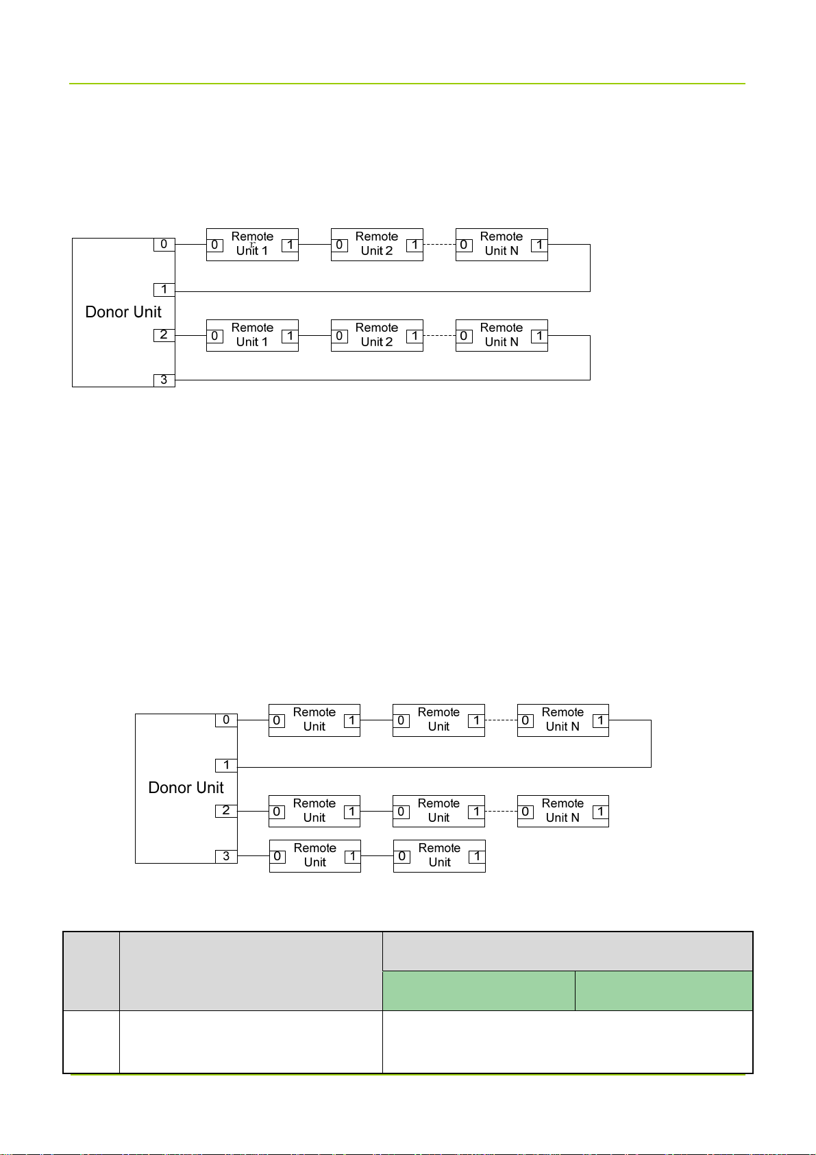
1.3.1
Star Topology
Low Configuration
For low configuration of star topology, each SFP port of the donor unit can connect to up to four remote
units, while one donor unit can connect to at most four remote units (N≤4).
4
User Manual Introduction
Remote
0 1
Unit
Remote
0 1
Unit
Donor Unit
0
1
Remote
0 1
Unit
Remote
0 1
Unit
0
1
Donor Unit
2
3
Remote
0 1
Unit
Remote
0 1
Unit
2
3
High Configuration
For high configuration of star topology, each SFP port of the donor unit can connect to up to eight remote
units, while one donor unit can connect to at most 16 remote units (N≤16).
1.3.2
Chain Topology
Low Configuration
For low configuration of chain topology, only one of the SFP ports on the donor unit is used and it can
connect to at most four remote units (N≤4).
Donor Unit
Remote
0 1 0 01 1
Unit 1
Remote
Unit 2
Remote
Unit N
High Configuration
For high configuration of chain topology, the SFP port on the donor unit can connect to at most eight
remote units (N≤8).
1.3.3
Ring Topology
Low Configuration
For low configuration of ring topology, the donor unit can form at most two rings, with each ring can
connect to up to two remote units; or the donor unit forms one ring and connects to four remote units.
5
Introduction User Manual
High Configuration
For high configuration of ring topology, at most two rings can be formed on the donor unit, with each ring
can connect to up to eight remote units (N≤8).
1.3.4
Hybrid Topology
Low Configuration
For low configuration of hybrid topology, each SFP port of the donor unit can connect up to four remote
units, while one donor unit can connect to at most four remote units.
High Configuration
For high configuration of hybrid topology, each SFP port of the donor unit can connect up to eight remote
units, while one donor unit can connect to at most 16 remote units.
1.4
Specifications
No. Item
1 Frequency Range
Downlink Uplink
460-470MHz(DL)
6
Specifications
450-460MHz(UL)

User Manual Introduction
Specifications
No. Item
Downlink Uplink
5 MHz (operating bandwidth)
2 Channel Bandwidth 25 kHz
3 Channel Capacity 1–8
4 Max. Output Power 5W
Cable-access: 50 dB±3
dB
1W
Cable-access: 45
dB±3 dB
5 Max. Gain
Wireless-access: 95
dB±3 dB
Wireless-access: 90
dB± 3 dB
6 Gain Adjustment Range/Step 30 dB/1 dB
7 Gain Adjustment Error
≤1 dB@ gain of 0–20 dB
≤1.5 dB@ gain of 21–30 dB
8 Noise Figure Wireless-access: ≤5 dB ≤5 dB
Cable-access: 10 dBm
9 Max. Input Level
Wireless-access: –10
–10 dBm
dBm
Output power variation < 2 dB or be off when adding 10
10 Automatic Level Control (ALC)
dB at max output power.
Control range≥20 dB.
11 In-Band Ripple ≤3 dB
12 Input/Output VSWR ≤1.5
13 Delay ≤35 μs
14 Frequency Offset ≤5×10
In-band ≤–15 dBm/30 kHz
Spurious
15
Emission
Out-of-band (2.5
MHz away from the
≤–36 dBm@9 kHz to 1 GHz
≤–30 dBm@1 GHz to 12.75 GHz
7
-8
ppm

Introduction User Manual
Specifications
No. Item
Downlink Uplink
band edge
≤–40 dBc@RBW3 kHz
8 CH 75 kHz Carrier Spacing
In-band
≤–45 dBc@RBW3 kHz
Intermodulation
16
Attenuation
2 CH 75 kHz Carrier Spacing
Out-of-band (2.5
MHz away from the
band edge)
17 Out-of-band Rejection (–6 dB)
18 Optical Bypass (optional)
19 Optical Loop
≤–36 dBm/100 kHz@9 kHz to 1 GHz
≤–30 dBm/1 MHz@1 GHz to 12.75 GHz
≤–20 dBc@±50 kHz
≤–25 dBc@±75 kHz
≤–30 dBc@±125 kHz
≤–63 dBc@±250 kHz
≤–67 dBc@±500 kHz
When the remote unit is powered down or the optical
path is faulty, the optical path is automatically bypassed,
and other cascaded remote units are not affected.
When the remote unit is powered down or the optical
path is interrupted, other cascaded devices can work
normally through the loop.
20 Network Topology Star, Chain, Ring, Hybrid and etc.
21 Optical Transmission Distance ≥20 km
22 Transmission Rate 1.25 GB/s, 2.5 GB/s, 3.02 GB/s, 6.04 GB/s (optional)
23 Optical TX Power –9.5 dBm to –3 dBm
24 Max. Optical RX Sensitivity –20 dBm
25 RF Connector N/F, 50 Ω
8

User Manual Introduction
Specifications
No. Item
Downlink Uplink
Donor Unit: LC/UPC
26 Fiber Connector
Remote Unit: LC/UPC
27 Power Supply Donor Unit /Remote Unit: 90 V to 264 V AC
Cable-access: ≤30 W
28
Power
Consumption
Donor Unit
Wireless-access: ≤100 W
Remote Unit ≤100 W
Cable-access Donor Unit: IP20
29 Ingress Protection Rating
30 Safety IEC 60950 Compliance
31 EMC IEC 61000 class B Compliance
32 Dimensions
33 Monitoring
Wireless-access Donor Unit: IP65
Remote Unit: IP65
Cable-access Donor Unit: 44 mm x 442 mm x 320
mm
Wireless-access Donor Unit: 142 mm x 300 mm x
385 mm
Remote Unit: 142 mm x 300 mm x 385 mm
Supports local monitoring and remote monitoring.
Local monitoring: RS232
Remote monitoring: SNMP
Internal Communication: RS485
34 MTBF ≥100,000 h
Cable-access Donor Unit: –10°C to +45°C
35 Operating Temperature
36 Storage Temperature –40°C to +85°C
Wireless-access Donor Unit: –25°C to +55°C
Remote Unit: –25°C to +55°C
9
Packing List User Manual
2. Packing List
Please unpack carefully and check that all items listed below are received. If any item is missing or
damaged, please contact us or your dealer.
2.1 Cable-access Donor Unit
Item Qty. Item Qty.
Main Unit 1 Cable Kit 1
Packing material for 19-inch Rack 1 Optical Cable Kit 1
Square Nut Kit 4 Power Cord 1
Crown Screw 4 Documentation Kit 1
2.2 Wireless-access Donor Unit
Item Qty. Item Qty.
Main Unit 1 Signal Cable (8-core) 1
Packing material 1 Power Cord 1
Mechanical parts of
1 Cable Kit 1
Die Casting Machine installation
Signal Cable (1-core) 1 Optical Cable Kit 1
Documentation Kit 1 / /
2.3 Remote Unit
Item Qty. Item Qty.
Main Unit 1 Signal Cable (8-core) 1
Packing material 1 Power Cord 1
Mechanical parts of
1 Optical Cable Kit 1
Die Casting Machine installation
Signal Cable (1-core) 1 SFP Optical Module 2
Documentation Kit 1 / /
10
User Manual Getting Started
3. Getting Started
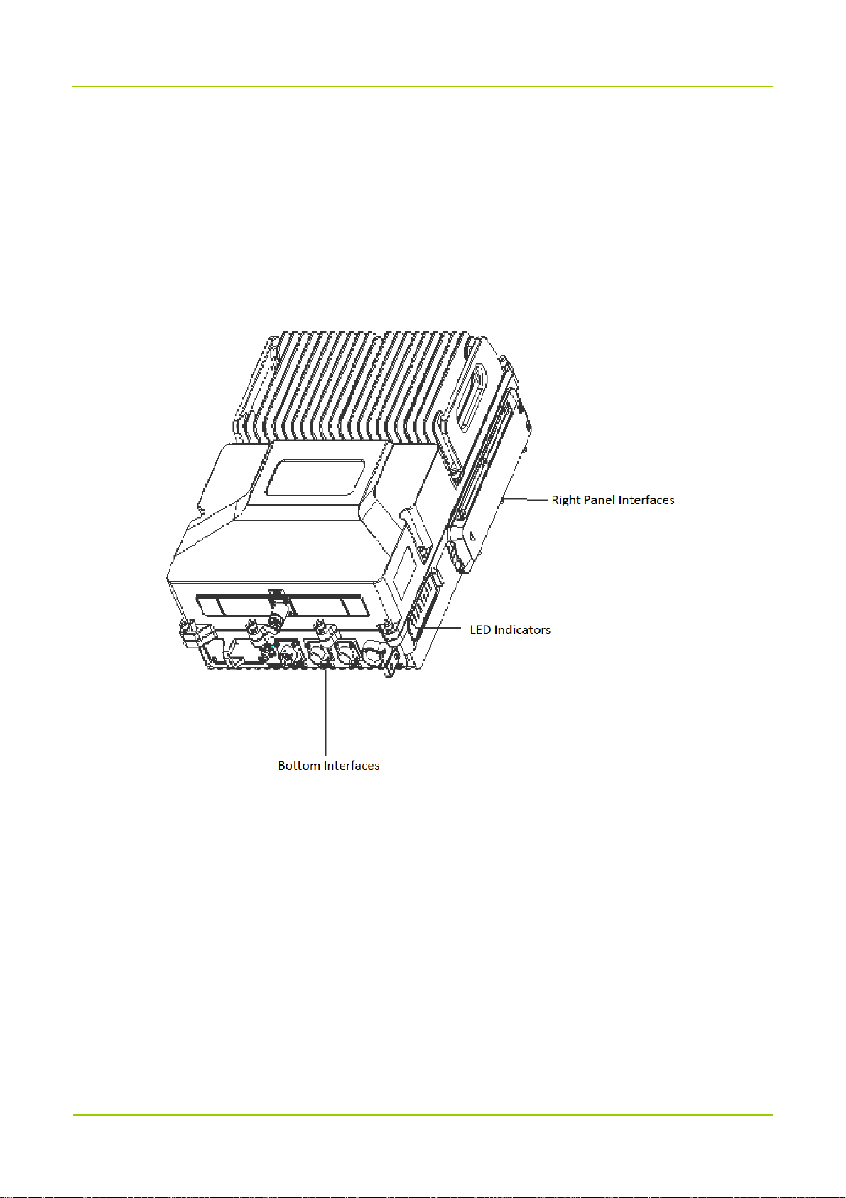
3.1 Appearance
DS-9300 adopts modular design. For the wireless-access donor unit and the remote unit, its LED
indicators and connectors are provided on the front and rear panels of the rack. The following figure shows
the appearance of the remote unit.
For the donor unit, its LED indicators are provided on the right side and connectors are provided on its
bottom and right side. The following figure shows the appearance of the donor unit.
11
Getting Started User Manual
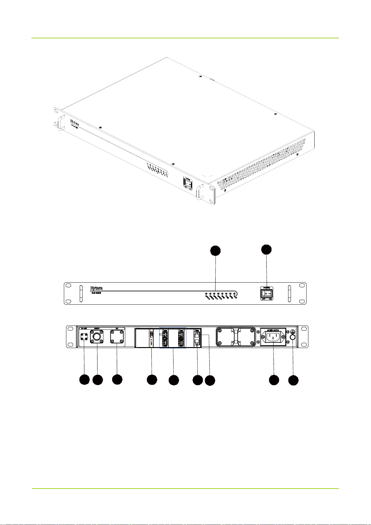
3.2 Donor Unit Interfaces
3.2.1
Cable-access Donor Unit
3
4
5 6
7 8
9
1
2
1010
11
12

User Manual Getting Started
3.2.2 Wireless-access Donor Unit
15
1
3.3 Remote Unit Interfaces
3
12
13
6
16
14
7
11
8
9
13
12
1
13
14
6
11
9
8
7

Getting Started User Manual
3.4 Interface Description
No. Label Meaning Connector Description
1 / LED indicators / See "3.6".
Single-pole-doubl
2 POWER Power switch
Modem antenna
3 MANT
connector
e-throw switch
SMA-F Reserved.
/
ANT port of the
4 BS/TX
5 RX RX port of the BS N/F
6 LOC
7 CPRI 0–3 Optical port
8 IP
9 Debug
duplexer, or TX
port of the BS
Local debug
interface
Remote
monitoring port
Optical module
debug interface
N/F
3-pin connector
SFP connector,
dual-layer
RJ45 port
RJ45 port
Connected to the ANT port of the
duplexer, or connected to the TX port of
the BS if the duplexer does not exist.
Connected to the RX port of the BS if the
duplexer does not exist.
Connected to computer through the serial
cable for debugging and monitoring.
The donor unit connects to remote units
through CPRI interface.
Connected to computer through the
network cable for remote debugging and
monitoring.
Interface for board debugging, used by
R&D engineers.
10
11 GND Ground terminal / /
12 AC Power inlet
13 EXM External alarm port
14 LCT
AC
Power inlet
90-264 V
Alarm port for 6-pin round
3-pin AC
connector
3-pin round
electric connector
8-pin round
electric connector
14
/
AC power inlet.
Connected to external devices that need
alarm monitoring.
Donor Unit: Monitors location change

User Manual Getting Started
No. Label Meaning Connector Description
location change
and door entry
15 BS RF interface N/F Connected to the donor antenna.
16 MS RF interface N/F Connected to the service antenna.
electric connector
(generates an alarm upon illegal
location change).
Remote Unit: Monitors location
change and the optical bypass switch.
3.5 Interface Definition
EXM
Pin No. Signal Name Definition Remarks
1 INT1 External alarm 1 Closed: Alarm; Open: No alarm.
2 INT2 External alarm 2 Closed: Alarm; Open: No alarm.
3 INT3 External alarm 3 Closed: Alarm; Open: No alarm.
4 GND Ground (signal) Common terminal.
Customized Alarm 1
5 OUT1 Reserved
Closed: Alarm; Open: No alarm.
6 GND Reserved Drive current: 10 mA (nominal), and 30 mA (max)
Customized Alarm 2
7 OUT2 Reserved
Closed: Alarm; Open: No alarm.
8 GND Reserved Drive current: 10 mA (nominal), and 30 mA (max)
LCT
Pin No. Signal Name Definition Remarks
Alarm for location
1 LCT
change
2 GND Ground /
Monitors location change of the devices.
3 DOOR Door entry alarm
Subjects to the chassis structure (available for cast
chassis).
15

Getting Started User Manual
Pin No. Signal Name Definition Remarks
4 GND Ground /
LOC
Pin No. Signal Name Definition Remarks
1 TX Data transmission Output.
2 RX Data receiving Input.
5 GND Ground /
3.6 LED Indicators
The LED indicators on the donor and the remote units indicate the running status.
LED
Indicator
ALM/VSWR Red
COM Green
PWR Green
RUN Green
CPRI 0 Green
Color Status Description
Off The device is running well.
Glowing or flashing The device malfunctions.
Glowing Remote communication works well.
Off Remote communication error.
Glowing The device is properly powered.
Flashing or off The device is not properly powered.
Flashing The device runs properly.
Glowing or off The device malfunctions.
Glowing Optical synchronization works well.
Flashing or off Optical synchronization error.
Glowing Optical synchronization works well.
CPRI 1 Green
Flashing or off Optical synchronization error.
Glowing Optical synchronization works well.
CPRI 2 Green
Flashing or off Optical synchronization error.
CPRI 3 Green Glowing Optical synchronization works well.
16

User Manual Getting Started
LED
Indicator
Color Status Description
Flashing or off Optical synchronization error.
17

Installation User Manual
4. Installation
4.1 Safety Information
Before performing any operation, read the following precautions and operation instructions carefully to
ward off potential risks.
Local Laws and Regulations
When installing a device, comply with the local safety laws and regulations.
Power Supply
Danger
Direct contact or indirect contact (through moist objects) with the high voltage or mains
electricity may result in fatal danger.
Non-standard and incorrect operations on the high-voltage power supply may result in fire
and electric shock.
Never wear conductive objects such as watches, bracelets and rings during operation.
Do use special tools when operating at high or AC voltage.
Do keep moisture out of the power system during operation in moist environment.
The equipment should be well earthed to avoid damage as a result of lightning strikes.
Do turn off the power before assembly or disassembly.
Do verify the cable specifications prior to connection.
Ensure that the equipment is well earthed before power-on.
Turn off the power immediately when the cabinet is found to get wet.
Make sure the power switch is toggled to the Off position before installing the equipment.
Working Aloft
Work performed more than 2 m (6.56 ft.) above the ground is regarded as work at heights.
While working at heights, stay alert to the following conditions.
Stop such work in any of the following conditions: adverse weather, wet steel tubes, and other risky
situations.
Set danger signs and prevent unauthorized person from entering the work area.
Avoid stacking scaffolds and other materials, and staying or passing below the aerial work platform.
18

User Manual Installation
Avoid dropping machinery and tools from the heights. Use strong ropes, hanging baskets or cable cars
to deliver tools.
Take sound safety actions such as wearing hamlets and safety belts properly.
Do wear heat-retaining clothes for working in cold areas.
Make sure the ladder is safe for use. Overload is strictly prohibited.
The slant of the ladder is suggested to be 75°. When using a ladder, place it on a stable ground, and
take protective measures on the base part of the ladder for skid resistance.
Handle and use all devices and tools with care to avoid falling.
Do not play or sleep on the aerial work platform.
Personnel
Installation and maintenance personnel must be trained to perform operations correctly and safely.
4.2 Installation Flow
Install DS-9300 device by following the installation flow below.
4.3 Preparation
19

Installation User Manual
4.3.1 Environment
Space Requirements
It is recommended that the space of at least 200 mm be left between the product top and the ceiling,
and 500 mm between the product bottom and the ground.
For product installed at its back, the space of at least 500 mm should be left at the right side, and 200
mm at the left side of product; for product installed at its left side, the space of at least 200 mm should
be left in front of product, and 200 mm in the back of product.
For product installed at its back, the space of at least 800 mm should be left in front of product; for
product installed at its left side, the space of at least 800 mm should be left at its right side.
Install the product upright at a proper position.
Environmental Protection
To ensure device reliability, install the devices in places with stable temperature.
Protection against Sun
If the devices are exposed to the sun, it is necessary to keep them well-ventilated and heat sinking. If
the temperature is more than 40°C, shielding device is required.
Protection against Rain, Water and Snow
The devices are rain proof, waterproof and snow proof. But temporary protective measures are needed
for maintenance.
Protection against Interferences
20

User Manual Installation
The devices should be installed far away from electromagnetic interferences such as large electric
devices.
Outdoor Installation and Maintenance
If the devices are installed outdoor, do not perform maintenance on extreme weathers such as storm,
extreme temperature or high humidity.
Grounding Requirements
The ground wire must be connected before device installation, and be removed after the device is
dismantled. Do not damage the grounding conductors.
Do not operate the devices when the grounding conductor is not installed.
The devices must be permanently grounded. Before any operation, please check the electrical
connection of the devices, making sure they are grounded properly.
4.3.2 Instruments and Tools
The following table lists the required tools:
Torx screwdriver, Philips driver, flat blade screwdriver, adjustable wrench, Allen
Regular Tools
Safety Tools
Cable Making Tools
Measuring Tools
Auxiliary Tools
wrench, cross-type torque screwdriver, combination wrench, rubber hammer,
and torque wrench.
Antistatic wrist strap, safety belt, helmet, safety rope, and slip-proof gloves.
Wire stripper, wire crimper, and wire cutter.
Multi-meter, tape measure, and level.
Fixed pulley, step ladder, marker pen, percussion drill, electrical tape, anti-UV
cable tie, label, screw kit, expansion screw, utility knife, heat gun, and duct tape.
4.3.3 Material Preparation
Before installation, check that all materials are well received according to the packing list.
4.4 Installing the Units
Place and fix the cable-access donor unit inside the cabinet.
The wireless-access donor unit and the remote unit can be mounted on a pole or wall as per needs. Check
latter chapters for more details.
21

Installation User Manual
4.4.1 Installation Parts
The following figure shows the parts needed for installation, including the auxiliary fixture, back panel,
latches and M6 screws.
AuxiliaryFixture
CaptiveScrew
BackPanel
M6Screw
Bolt
4.4.2 Installing the Product
Installation on Pole
You can install the product at its back or at its left side. The pole diameter should be between 60 mm to 114
mm.
Installing at Back
1. Mark the installation position of the auxiliary fixture on the pole by using a marking pen.
2. Place the auxiliary fixture onto the pole, insert four bolts into the auxiliary fixture and then tighten four
nuts by using a torque wrench.
3. Secure the back panel onto the back of the product using four M6 screws.
22

User Manual Installation
4. Insert the back panel into the auxiliary fixture and tighten the captive fasteners on the back panel of the
product.
Installing at Left Side
Installing the product at left side and installing the product at back are almost the same. The only difference
is that the back panel is secured to the left side rather than back of the product. The following figure shows
the product installed at its left side.
23

Installation User Manual
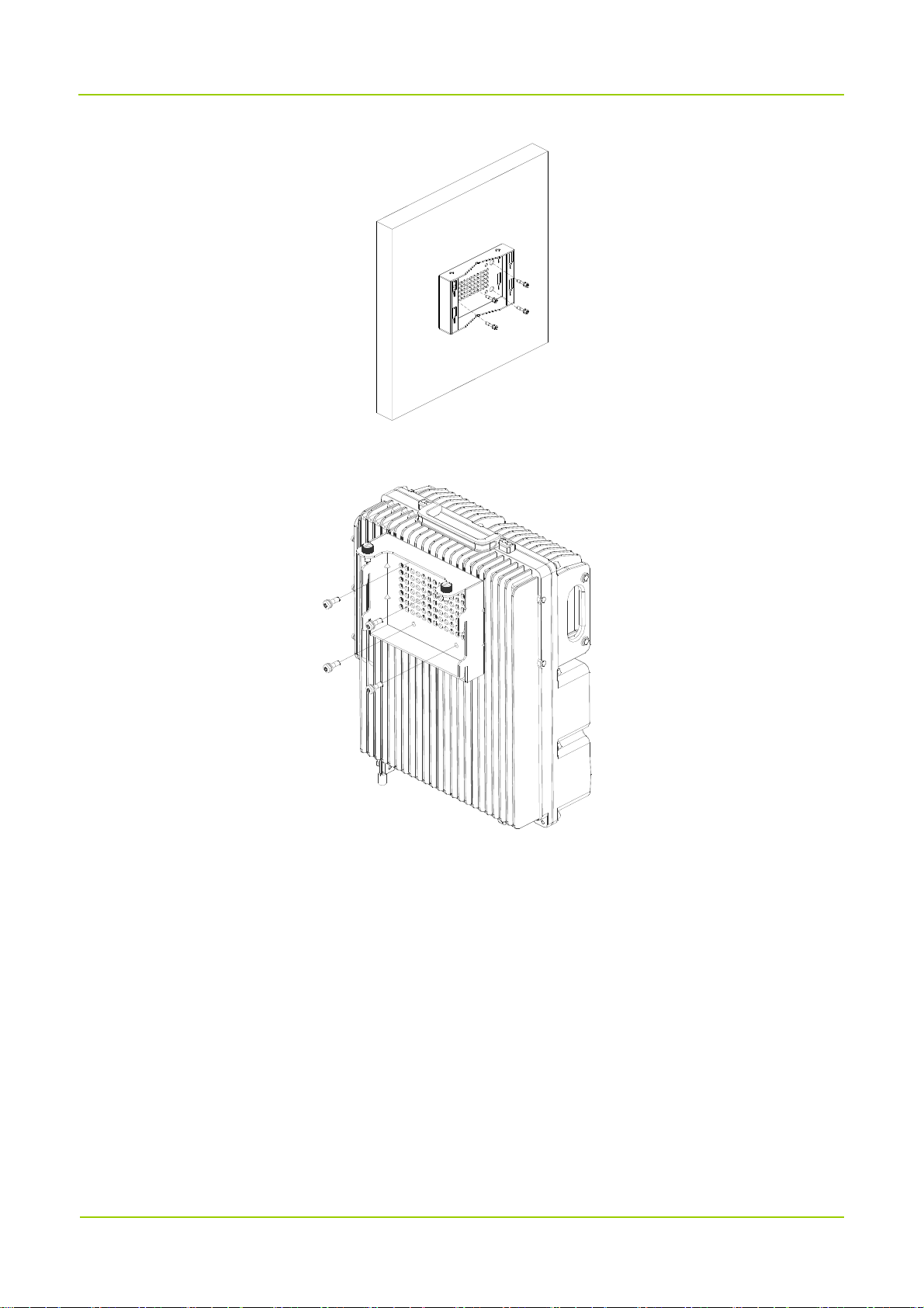
Installation on Wall
You can install the product on a wall at the back or left side of the product.
Installing at Back
1. Place the auxiliary fixture on the wall at the installation position and then mark the anchor points by
using a marking pen.
2. Drill holes at the anchor points and then install the expansion bolt assemblies.
3. Fit the auxiliary fixture on the expansion bolts, and then tighten the bolts.
24
User Manual Installation
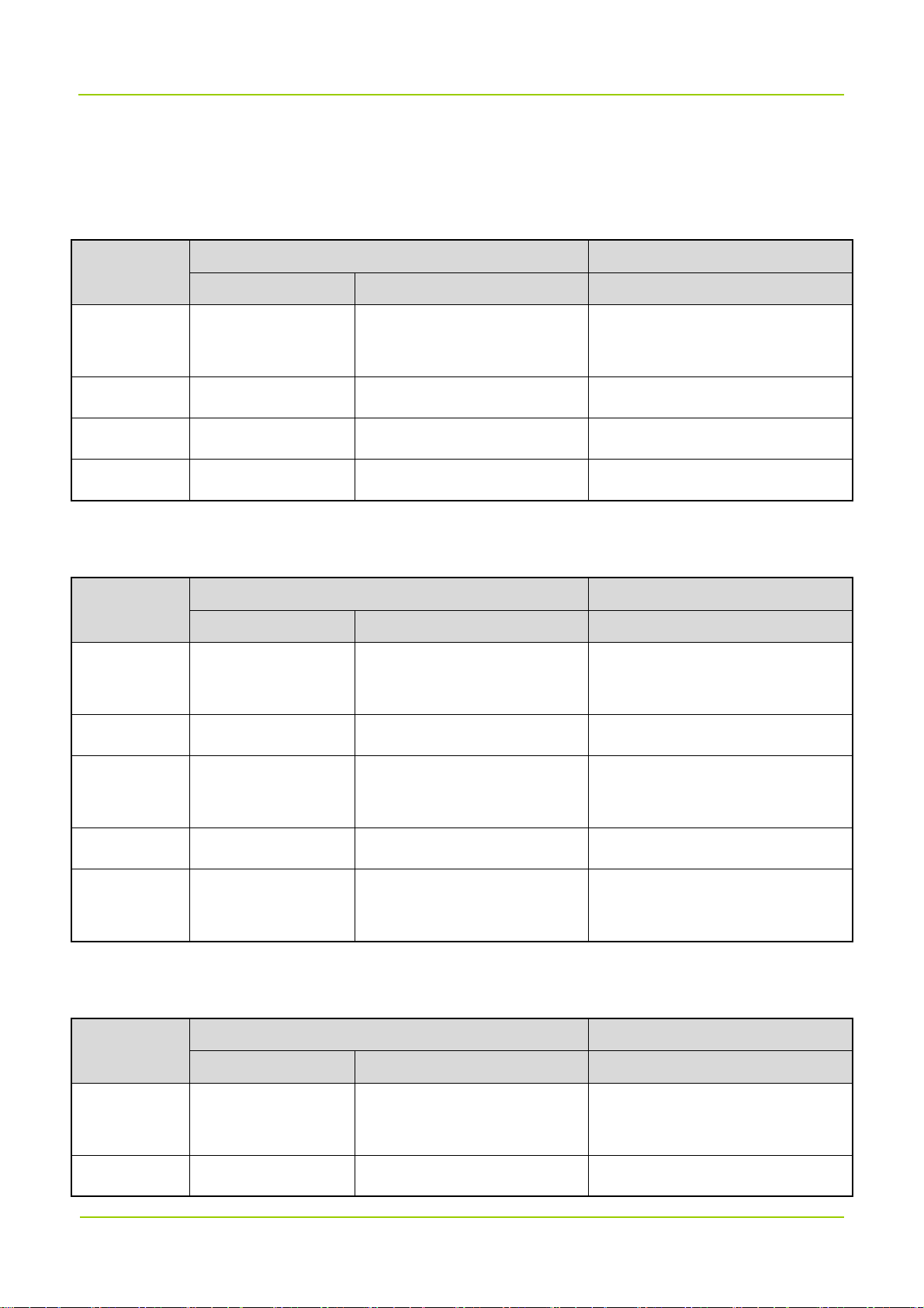
4. Secure the back panel onto the back of the product using four M6 screws.
5. Insert the back panel into the auxiliary fixture and tighten the captive fasteners on the back panel of the
product.
25

Installation User Manual
Installing at Left Side
Installing the product at left side and installing the product at back are almost the same. The only difference
is that the back panel is secured to the left side rather than back of the product. The following figure shows
the product installed at its left side.
26

User Manual Installation
4.4.3 Cabling
Cabling Requirements
Lay out cables according to requirements to reduce interference between them.
Safety Requirements
Lay out cables away from sharp objects or jagged walls, or protect cables using conduit.
Lay out cables away from heat sources, or add heat-insulation materials between cables and heat
sources.
Requirements for Binding Cables
Bind same cables together.
Bind cables securely and neatly, without damaging the cable jackets.
Ensure that cable ties face the same direction and are aligned in rows horizontally.
After installing cables, attach labels or tags to the two ends of each cable.
Cables of different types cannot be crossed.
Requirements for Laying Out Power Cables
The routing of power cables must meet engineering design drawing requirements.
If the power cable length is insufficient, replace the power cable. The power cable must be complete
and cannot have splices or welding points.
Avoid knotting or twisting the cable.
Requirements for Laying Out Grounding Cables
The grounding cable cannot be led in aerially, but buried in the earth or arranged indoor.
The grounding cables must be separated from signal cables to reduce interference between them.
All metal components in the chassis must be securely connected to the grounding cable.
Requirements for Laying Out Optical Fibers
Do not bind optical fibers where they are bent.
Do not press optical fibers forcibly or crush optical fibers with force. Leave sharp objects away from
optical fibers to prevent damage to optical fibers.
Coil up redundant optical fibers around specialized devices such as the splice tray.
Optical jumpers must be bound with optical fiber tapes. If the fiber is required to be fixed on the cabinet
or device, then use the cable tie to bind the fibers on the optical fiber tape. Attention that the optical fiber
must be flexible in the cable tie, and must not be bent into 90° angle.
Coil optical fibers gently and do not break them.
27
Installation User Manual
Cover idle optical fiber connectors with protective caps.
Cable List
Cable-access Donor Unit Cable List
One end (at DS-9300 device) Other end
Cable
Connector Connected to …… Connected to ……
Grounding
Cable
RF Antenna N-M
Power Cable 3-pin AC Connector AC 90-264 V External Power Supply
Optical Fiber SFP/SFP+ CPRI 0–3 Fiber Optic Network
Ring Terminal Ground Terminal Grounding Bar
RX/TX/BS Interfaces Base Station
Wireless-access Donor Unit Cable List
One end (at DS-9300 device) Other end
Cable
Connector Connected to …… Connected to ……
Grounding
Cable
RF Antenna N-M
Ring Terminal Ground Terminal Grounding Bar
BS Interface Antenna System
Power Cable
Optical Fiber SFP/SFP+ CPRI 0–3 Interfaces Optical Fiber Network
Monitoring
Cable
Round Electric
AC Interfaces External Power Supply
Connector
8-pin/1-pin Aviation
EXM/LCT Interfaces External Monitoring Device
Connector
Remote Unit Cable List
One end (at DS-9300 device) Other end
Cable
Connector Connected to …… Connected to ……
Grounding
Ring Terminal Ground Terminal Grounding Bar
Cable
RF Antenna N-M
MS Interface Antenna System
28

User Manual Installation
One end (at DS-9300 device) Other end
Cable
Connector Connected to …… Connected to ……
Power Cable
Optical Fiber SFP/SFP+ CPRI 0–1 Interfaces Optical Fiber Network
Monitoring
Cable
Round Electric
AC Interfaces External Power Supply
Connector
8-pin/1-pin Aviation
EXM/LCT Interfaces External Monitoring Device
Connector
Cabling Guide
Cable-access Donor Unit
29

Installation User Manual
Wireless-access Donor Unit
Remote Unit
Installing the Grounding Cable
1. According to the route, make a grounding cable with proper length, and install ring terminals at both
ends of the cable.
30

User Manual Installation
The metal wires must be completely sealed, as shown in the figure below.
2. Connect one end of the cable to the ground connector at bottom of DS-9300 and the other end to the
grounding bar.
3. Attach labels or tags to the installed cable.
Installing the RF Antenna
1. Remove protective caps from the antenna connector.
2. Connect the male end of the RF cable to the BS interface of the donor unit or the MS interface of remote
unit and tighten the connector using the torque wrench.
3. Connect the donor unit to the coupler, and connect the other end of the RF antenna from the remote
unit to the service antenna.
If the antenna is installed outdoor, it needs to be connected to a lightning arrestor. In this case, the other
end of the RF antenna connects to the lightning arrestor.
4. Waterproof the cable connectors.
a. Wrap a layer of PVC insulation tape around the cable connector from bottom to top.
b. Wrap three-layer waterproof tape over the PVC insulation tape. Starting from 50 mm from the
bottom of the antenna connector, wrap the three-layer waterproof tape in the following patterns:
31

Installation User Manual
bottom to top, top to bottom, and bottom to top again. Cut off the tape after the three-layer is done.
Tighten the tape at each layer to ensure waterproof.
c. Wrap three-layer PVC insulation tape over the waterproof tape. Starting from 30 mm from the
bottom of the waterproof tape, wrap the three-layer PVC insulation tape in the same method as
introduced in step b.
d. Bundle cable ties at 3–5 mm from both ends of the tape.
5. Check the dustproof cap of the antenna connector, and waterproof it in the same method as introduced
in step 4.
6. Waterproof idle connectors on the bottom of DS-9300 device without removing the protective caps,
according to step 4.
7. Lay out the cable according to design requirements and fix the cable with cable ties.
8. Attach labels or tags to the installed cable.
Installing the Power Cable
Note
Power cable delivered with DS-9300 device is 3*18 AWG cable.
1. Connect one end of the power cable to the PWR connector of DS-9300 device and the other end to the
external power supply. Lay out the cable according to design requirements and fix the cable with cable
ties.
3. Attach labels or tags to the installed cable.
Installing the Monitoring Cable
1. Remove protective cap from the EXM/LCT connector of DS-9300 device. Connect one end of the
monitoring cable to the EXM/LCT connector of DS-9300 device and the other end to the external
monitoring device.
3. Lay out the cable according to design requirements and fix the cable with cable ties.
4. Attach labels or tags to the installed cable.
Installing the Optical Fiber
The remote unit receives signals from the donor unit at CPRI 0 and outputs signals to the connected
remote unit at CPRI 1, as shown in the following figure.
32

User Manual Installation
Procedure of installing the optical fiber is described as follows:
1. Connect the optical module to the SFP connector of DS-9300 device, as shown in the following figure.
Note
DS-9300 device adopts a dual-fiber single mode optical module with a transfer rate of 1.25 Gbps, a
wavelength of 1,310 nm and a communication distance of 20 km.
1
a. Rotate the bail clasp latch down.
b. Insert the optical module into the SFP connector.
c. Rotate the bail clasp latch back.
2
3
2. Connect the fiber pigtail to the optical module and the other end of the fiber to the external transmission
device, as shown in the figure below.
33

Installation User Manual
3. Lay out the cable according to design requirements and fix the cable with cable ties.
4. Attach labels or tags to the installed cable.
4.5 Post-installation Check
4.5.1
Check the cables according to the table below.
No. Item
Checking the Installation
The device is installed by strictly following the design draft. The installing position meets space
1
requirements with maintenance space reserved.
2 The device is securely installed.
3 Waterproof caps are installed on idle connectors and securely fastened.
All power cables or grounding cables are not short-circuited or reversely connected and must be
4
intact with no damage.
5 The power cables and grounding cables are separated from other cables and bundled separately.
Connectors of all cables are complete, intact, and tightly connected. The cables are not damaged
6
or broken.
7 Labels on cables, feeders and jumpers are clear and correct.
4.5.2 Checking the Device with Power On
After the installation is complete, observe indicators on DS-9300 device to determine the system running
status.
34

User Manual Installation
If the RUN indicator flashes green and the ALM indicator is off, the status of DS-9300 device is normal.
35

Power On and Power Off User Manual
5. Power On and Power Off
5.1 Powering On
Toggle the power switch on DS-9300 device to the ON position to power it on. Wait a few minutes and
check the status of LED indicators.
5.2 Powering Off
Toggle the power switch on DS-9300 device to the OFF position to power it off.
36

User Manual Debugging
6. Debugging
Use the Product Support Software (PSS) to configure and upgrade the DS-9300 device.
6.1 Preparation
Before debugging, prepare the PSS tool, and connect the device to the computer. You can debug the
device either locally through the cable or IP connection, or remotely through IP connection. The default IP
address of the device is 192.168.1.100; the IP address of the computer must be set to the same network
segment, 192.168.1. X (X cannot be 100).
The computer for running the PSS must meet requirements specified in the following table:
Item Description
Operating system Windows7 or above
CPU PII300 or above
Memory 128 MB or above
Storage 2 GB or above
Display 14-inch or above, resolution 800x600 or above
6.2 Procedure
The process of local debugging and remote debugging is the same. In this document, local debugging is
taken as example. For remote debugging, please refer to Repeater Management System Operation Guide.
1. Double-click "DS9300_PSS.exe" on the computer. The following main interface appears.
37

Debugging User Manual
2. Click Project, select DS_9300_CUSTOMER and click Lock. A message indicating locking database
succeeded will appear in the message pane.
3. Select Ethernet tab, set the Destination and Port and click Connect.
Note
For debugging through the serial cable, select the Serial tab, set the Serial and Baudrate
(115200) and click Connect.
4. Click Scan and the following window appears.
5. Select devices you want to display on the PSS and click OK.
38

User Manual Debugging
6.2.1
To manually query parameters of the selected device, click Query Parameter.
If you click Auto Query, PSS will query all the parameters of the selected device every two seconds.
In the Scan list, click on the device and check Select All. Click Query Parameter, the parameter values
will be displayed in Status.
Querying Parameters
Note
To query a specific parameter, check the parameter name and click Query Parameter.
To query all parameters on the line, click the blank tab above the checkbox as shown in the figure
below.
6.2.2
1. In the parameter list, click the blank space under Setting tab from the same row the parameter locates
Setting Parameters
(the parameter is thus checked by default), enter or select a value. For the detail description of each
parameter, see chapter Appendix: Parameters.
a. (Optional for channel-selective devices) Select
switch of the current BS, then set the corresponding uplink and downlink working channel frequencies.
Parameter Settings
tab, and turn on the channel
Other spare channel switches need to be turned off.
39

Debugging User Manual
Note
For remote units, set the Downlink Output Under-power Threshold 10 dBm less than the actual
output power in most cases.
b. Select
parameter should be around -13 dBm for a cable-access donor unit, and -58 dBm for a wireless-access
donor unit. In case the differences are large, add attenuators to the power input port of the cable-access
donor unit according to the difference value, or adjust the corresponding donor antenna of the
wireless-access donor unit.
c. Select the
Parameter Value
IP Address
IP Mask
IP Gateway
Real-time Sampling
Device Information
This parameter is subject to actual requirements. The default value is
192.168.1.100.
This parameter is subject to actual requirements. The default value is
255.255.255.0.
This parameter is subject to actual requirements. The default value is
192.168.1.1. The first three numbers must be consistent with that of the
device IP address, the last number must be 1.
tab, and view the
tab, and modify the configuration according to the following table.
Downlink Input Power Level
. The value of this
Device No.
The donor unit is 0; the range for remote unit in low configuration is 1 to 4;
the range for remote unit in high configuration is 1 to 16.
40

User Manual Debugging
d. Select the
configured. When an alarm is generated, it will be alerted in red font and needs handling.
2. Click Setting, the result will be displayed in the message pane.
Alarm Status
tab, and turn on all switches if a repeater management system (RMS) is
Note
To restore the factory settings, click Factory Reset.
6.2.3
PSS allows you to upgrade the main program of the monitor board and the main program and FPGA of the
digital board.
1. In the Upgrade area, click Load.
2. Select the software and click Upgrade. The result will be displayed in the message pane.
Upgrade
41

Debugging User Manual
Note
If the upgrade fails or you want to roll back to the former version, perform the upgrade using the old
upgrade file.
6.2.4 Exporting the Logs
PSS allows you to export the operation logs.
1. In the Log area, click Path.
2. Specify the storage path and click Start.
42

User Manual System Maintenance
7. System Maintenance
7.1 Care and Cleaning
To guarantee optimal performance as well as a long service life of the product, please follow the tips below.
Caution
Be sure to turn off the product before cleaning.
Product Care
Attach the connector cover with waterproof plug when the connector is not in use.
Do not pierce, strike, throw or scrape the product.
Keep the product away from substances that can corrode the circuitry.
Keep the device dry.
Keep this device far away from overheating, which may shorten lifespan of the electronic parts, or even
distort or melt the plastic parts.
Keep this device far away from extreme cold. Otherwise, the circuit board may be damaged by vapor
generated when the device is used at normal temperature.
Product Cleaning
Clean up the dust and fine particles on the product surface and charging piece with a clean and dry
lint-free cloth or a brush regularly.
Use a non-woven cloth with neutral cleanser to clean the device after long-time use. Do not use
chemical preparations such as stain removers, alcohol, sprays or oil preparations, so as to avoid
potential damage on the surface. Make sure the product is completely dry before use.
7.2 Routine Maintenance
To ensure reliable communication, it is recommended to perform the following check tasks on a regular
basis:
Check whether the return loss of the antenna feeder system is normal, whether the position and
direction of the antenna are changed, and whether the RF cable connectors are properly sealed.
Check whether the indoor cables are moved, whether the fixed devices are loosened, and whether the
power connection is in good condition.
Check whether the lightening arrestor and the grounding are in good condition.
Check whether the power voltage of the device is normal.
43

System Maintenance User Manual
Regularly check and record the working status and main parameters such as receiving signal level,
output noise level, and downlink output power.
Check whether the coverage meets the requirements.
Check whether the monitoring system works properly.
Check whether the signs and labels on the devices are complete.
If the device malfunctions, return it for repair.
7.3 Alarm Handling
Alarm Information Solution
Check whether the power supply and signal cable connection of the LNA and
LNA and PA Alarm
PA modules are in good condition. If the alarm still exists, replace the module.
Power Fault and Power
Down Alarm
PA Over-temperature
Alarm
Door Alarm
Location Alarm
Downlink VSWR Alarm
If the power down alarm is generated, check whether the AC power connection
is in good condition, and whether the power supply is normal.
Change the temperature threshold to clear the alarm. It's recommended to set
the maximum temperature threshold to 90°C. If the alarm still exists, cool the
device down.
Check whether the cabinet door is properly closed. If the alarm still exists after
the door is closed, check whether the door and the alarm cable are properly
connected.
Check whether the device is moved illegally. If not, check whether the alarm
cable is properly grounded.
Check whether the SWR threshold of the downlink PA is set correct. It is
recommended to set the threshold as 3.0. If the alarm does not disappear,
check whether the antenna system is connected well, or flooded with water. It
is recommended to use a VSWR tester to test the actual SWR threshold.
Uplink/Downlink
Input/Output
Over-power/Under-power
Alarm
Change the input/output over-power/under-power thresholds to clear the
alarm. It is recommended to set the thresholds as follows:
Uplink Output Over-power Threshold (Donor Unit): 0 dBm (nominal
downlink output power)
Downlink Input Over-power Threshold (Donor Unit): –5 dBm
Downlink Output Under-power Threshold (Remote Unit): +25 dBm (nominal
44

User Manual System Maintenance
Alarm Information Solution
downlink output power)
7.4 Troubleshooting
Phenomena Possible Cause Solution
The device fails to be
powered on.
The RUN indicator glows
green solidly.
The RUN indicator is off.
The ALM indicator glows
red solidly.
The ALM indicator flashes
red.
The power cable is not connected, or the
contact with the socket is loose.
The unit is powered, but a module is
faulty.
The unit is not powered, or a module is
faulty.
A module is faulty. Replace the faulty module.
A connector is faulty. Check the connector.
Connect the power cable
properly and ensure good
contact.
Troubleshoot or replace the
faulty module.
Check whether the power cable
is properly connected, or
troubleshoot the faulty module.
Or replace the faulty module, if
necessary.
The VSWR indicator
flashes red rapidly.
The VSWR indicator
flashes red slowly.
The SFP indicator is off. The optical fiber link is faulty.
If the above solutions cannot fix your problem, please contact us.
One or more ports generate VSWR alarm
during starting of the unit.
One or more channels are abnormal after
the cell is set up.
45
Check whether the connection of
the antenna system is proper.
Check whether the connection of
the antenna system is proper.
Check whether the fiber and the
optical module are properly
connected.

Appendix: Parameters User Manual
8. Appendix: Parameters
Take the donor unit as example.
Device Information
Parameter Configuration Remarks
Electronic Serial Number
(ESN)
Monitor Version Keep the default value unchanged. Version of the monitor board.
FPGA Version Keep the default value unchanged.
Application Version Keep the default value unchanged.
IP Address
Subnet Mask
Enter up to 10 characters, including digits
and letters.
This parameter is subject to actual
requirements. The default value is
192.168.1.100.
This parameter is subject to actual
requirements. The default value is
255.255.255.0.
Serial number of the device.
Version of FPGA in the digital
modules.
Version of applications in the
digital modules.
/
/
Default Gateway
Site ID
This parameter is subject to actual
requirements. The default value is
192.168.1.1. The first three numbers must
be consistent with that of the device IP
address, the last number must be 1.
The range is 0 to 4294967295. The site ID
must end with the ID of its home BS. For
example, if a donor unit has a site ID of
20001, then "2" represents the donor unit
ID and "0001" represents the home BS
ID; if the remote unit has a site ID of
160020001, then “16” represents the
remote unit ID, “002” represents the home
donor unit ID, and “0001” represents the
46
/
The only ID of the device,
consistent with its configuration
in the repeater management
system (RMS).

User Manual Appendix: Parameters
home BS ID.
The donor unit is 0; the range for remote
Device number of
Device No.
unit in low configuration is 1 to 4; the
corresponding donor or remote
range for remote unit in high configuration
units.
is 1 to 16.
The range is 0 to 255.
Manufacturer ID
Device Type
1: Hytera
2: Reserved
The range is 1 to 13.
1: DCCD
2: DCR
3: DICR
4: LA
5: DWCD
6: DCBD
7: DBR
8: DWBD
9: DCCD L
10: DWCD L
/
/
Device Number
Device Description
Device Longitude
11: DCBD L
12: DWBD L
13: Reserved
Enter up to 20 characters, including digits
and letters.
Enter up to 20 characters, including digits
and letters.
This parameter is subject to actual
requirements.
Negative number represents South
47
Material number of the device.
Material description of the
device.
/

Appendix: Parameters User Manual
Latitude or West Longitude.
This parameter is subject to actual
requirements.
Device Latitude
Negative number represents South
Latitude or West Longitude.
The range is 0 to 2.
Communication Method for
1: SNMP
Reporting Alarms
2: Reserved
/
/
This parameter is subject to actual
Monitor Center IP Address
requirements.
The range is 0 to 65535. This parameter
Monitor Center Port No.
is subject to actual requirements.
This parameter is subject to actual
Site Description
requirements.
Real-time Sampling
Parameter Configuration Remarks
Manufacturer ID The range is 0 to 255. /
Location Area ID The range is 0 to 65535. /
Source BS ID The range is 0 to 4294967295. /
BCCH Absolute Carrier No. The range is 0 to 65535. /
IP address of the RMS Monitor
Center.
Port number of the RMS
Monitor Center.
/
BCCH Receiving Level The range is –127 to 127. /
The range is 1 to 4.
1: PDT
Signal Format
Max. Working Channels Keep the default value unchanged.
2: DMR
3: TETRA
4: Others
48
/
Only available on
channel-selective devices.

User Manual Appendix: Parameters
Actual Number of Carriers The range is 0 to 32.
Downlink Input Power Level
(dBm)
Uplink Output Power Level
(dBm)
Remote Unit Online Switch
Remote Unit Connection
Indicator
Donor Unit Connection
Indicator
The range is –110 to 10. /
The range is –110 to 50. /
0: Offline
1: Online
0: Not connected
1: Connected
0: Not connected
1: Connected
Actual number of channels the
device has opened.
Whether the remote unit is
online.
Whether a remote unit is
connected.
Whether a donor unit is
connected.
Setting Parameters
Parameter Configuration Remarks
Downlink Input Over-power
The range is –110 to 10. /
Threshold (dBm)
Uplink Output Over-power
The range is –110 to 50. /
Threshold (dBm)
System Uplink Gain (dB) The range is 0 to 100. /
System Downlink Gain (dB) The range is 0 to 100. /
Uplink Channel Reference
Base Frequency (MHz)
Downlink Channel
Reference Base Frequency
(MHz)
This parameter is subject to actual
requirements.
This parameter is subject to actual
requirements.
/
/
Increment (kHz)
This parameter is subject to actual
/
requirements.
49

Appendix: Parameters User Manual
1: Report
Inspection Report
0: Do not report
1: Report
Troubleshooting Report
0: Do not report
/
/
Configuration Change
Report
Downlink PA Over-current
threshold
Uplink/Downlink Squelch
Threshold (dBm)
Uplink/Downlink Squelch
Switch
Remote Unit Delay
Auto-compensation Switch
Uplink Digital Attenuation
(dB)
Downlink Digital
Attenuation (dB)
1: Report
0: Do not report
The range is 0 to 65535.
The range is –110 to 50. /
0: Enable
1: Disable
0: Enable
1: Disable
The range is 0 to 20. /
The range is 0 to 20. /
/
/
/
/
Monitor Board Software
Version Switch
Digital Board Software
Version Switch
FPGA Software Version
Switch
Uplink Operating Channel
(MHz)
Downlink Operating
Channel (MHz)
0: Do not switch
/
1: Switch
0: Do not switch
/
1: Switch
0: Do not switch
/
1: Switch
This parameter is subject to actual
/
requirements.
This parameter is subject to actual
/
requirements.
50

User Manual Appendix: Parameters
0: Disable
Channel Switch
1: Enable
/
Alarm Status
Parameter Configuration
0: Disable
Master-Slave Monitoring Link Fault Alarm Enable
1: Enable
0: Disable
Power Supply Disconnection Alarm Enable
1: Enable
0: Disable
Power Supply Fault Alarm Enable
1: Enable
Downlink Input Over-power Alarm Enable
Uplink Output Over-power Alarm Enable
Uplink Local Oscillator Unlock Alarm Enable
Downlink Local Oscillator Unlock Alarm Enable
Remote Digital Module Fault Alarm Enable
Downlink LNA Fault Alarm Enable
0: Disable
1: Enable
0: Disable
1: Enable
0: Disable
1: Enable
0: Disable
1: Enable
0: Disable
1: Enable
0: Disable
1: Enable
Optical Receiving Alarm Enable
Optical Transmission Alarm Enable
Downlink PA Over-current Alarm Enable
0: Disable
1: Enable
0: Disable
1: Enable
0: Disable
51

Appendix: Parameters User Manual
Master-Slave Monitoring Link Fault Alarm
Power Supply Disconnection Alarm
Power Supply Fault Alarm
Downlink Input Over-power Alarm
Uplink Input Over-power Alarm
Downlink PA Over-current Alarm
1: Enable
0: Normal
1: Fault
0: Normal
1: Fault
0: Normal
1: Fault
0: Normal
1: Fault
0: Normal
1: Fault
0: Normal
1: Fault
Uplink Local Oscillator Unlock Alarm
Downlink Local Oscillator Unlock Alarm
Remote Digital Module Fault Alarm
Downlink LNA Fault Alarm
Optical Receiving Alarm
Optical Transmission Alarm
0: Normal
1: Fault
0: Normal
1: Fault
0: Normal
1: Fault
0: Normal
1: Fault
0: Normal
1: Fault
0: Normal
1: Fault
52
 Loading...