


Preface
Thanks for your favor in our product. To derive optimum performance from the product, please read
this manual and the supplied Safety Information Booklet carefully before use.
This manual is applicable to the following model:
X1p Digital Portable Radio

Copyright Information
Hytera is the trademark or registered trademark of
Hytera Communications Co., Ltd. (the Company) in
PRC and/or other countries or areas. The Company
retains the ownership of its trademarks and product
names. All other trademarks and/or product names
that may be used in this manual are properties of
their respective owners.
The product described in this manual may include
the Company’s computer programs stored in memory
or other media. Laws in PRC and/or other countries
or areas protect the exclusive rights of the Company
with respect to its computer programs. The purchase
of this product shall not be deemed to grant, either
directly or by implication, any rights to the purchaser
regarding the Company’s computer programs. Any
of the Company’s computer programs may not be
copied, modied, distributed, decompiled, or reverse-
engineered in any manner without the prior written
consent of the Company.
The AMBE+2TM voice coding technology embodied
in this product is protected by intellectual property
rights including patent rights, copyrights and trade
secrets of Digital Voice Systems, Inc. This voice
coding technology is licensed solely for use within
this product. The user of this technology is explicitly
prohibited from attempting to decompile, reverse
engineer, or disassemble the Object Code or in any
other way convert the Object Code into a human
readable form.
U.S. Patent Nos. #6,912,495 B2, #6,199,037 B1,
#5,870,405, #5,826,222, #5,754,974, #5,701,390,
#5,715,365, #5,649,050, #5,630,011, #5,581,656,
#5,517,511, #5,491,772, #5,247,579, #5,226,084 and
#5,195,166.
Disclaimer
The Company endeavors to achieve the accuracy
and completeness of this manual, but no warranty of
accuracy or reliability is given. All the specications
and designs are subject to change without notice due
to continuous technology development. No part of
this manual may be copied, modied, translated, or
distributed in any manner without the express written
permission of us.
We do not guarantee, for any particular purpose,
the accuracy, validity, timeliness, legitimacy or
completeness of the Third Party products and
contents involved in this manual.
If you have any suggestions or would like to learn
more details, please visit our website at: http://www.
hytera.com.
RF Radiation Information
This product must be restricted to operations in an
Occupational/Controlled RF exposure Environments.
The product must be only used by users who are
fully aware of the hazards of the exposure and who
are able to exercise control over their RF exposure to
qualify for the higher exposure limits.
RF Radiation Prole
Radio Frequency (RF) is a frequency of
electromagnetic radiation in the range at which radio
signals are transmitted. RF technology is widely used
in communication, medicine, food processing and
other elds. It may generate radiation during use.
RF Radiation Safety
In order to ensure user health, experts from relevant
industries including science, engineering, medicine
and health work with international organizations to
develop standards for safe exposure to RF radiation.
These standards consist of:
● United States Federal Communications
Commission, Code of Federal Regulations;
47CFR part 2 sub-part J;
● American National Standards Institute (ANSI)/
Institute of Electrical and Electronic Engineers
(IEEE) C95. 1-1992;
● Institute of Electrical and Electronic Engineers
(IEEE) C95. 1 – 1999;
● International Commission on Non-Ionizing
Radiation Protection (ICNIRP) 1998;
FCC Regulations
Federal Communication Commission (FCC) requires
that all radio communication products should meet
the requirements set forth in the above standards
before they can be marketed in the U.S, and the
manufacturer shall post a RF label on the product
to inform users of operational instructions, so as to
enhance their occupational health against exposure
to RF energy.
Operational Instructions and
Training Guidelines
To ensure optimal performance and compliance
with the occupational/controlled environment RF

energy exposure limits in the above standards and
guidelines, users should transmit no more than
50% of the time and always adhere to the following
procedures:
Your radio radiates measurable RF energy only
while it is transmitting (during talking), not when it is
receiving (listening) or in standby mode.
FCC Statement
This equipment has been tested and found to
comply with the limits for a Class B digital device,
pursuant to part 15 of FCC Rules. These limits are
designed to provide reasonable protection against
harmful interference in a residential installation.
This equipment generates and can radiate radio
frequency energy and, if not installed and used in
accordance with the instructions, may cause harmful
interference to radio communications. However, there
is no guarantee that interference will not occur in a
particular installation. If this equipment does cause
harmful interference to radio or television reception,
which can be determined by turning the equipment
off and on, the user is encouraged to try to correct.
The interference by one or more of the following
measures:
● Reorient or relocate the receiving antenna.
Increase the separation between the equipment
and receiver.
● Connect the equipment into an outlet on a
circuit different from that to which the receiver is
connected.
● Consult the dealer or an experienced radio/TV
technician for help
Operation is subject to the following two conditions: 1.
This device may not cause harmful interference, and
2. This device must accept any interference received,
including interference that may cause undesired
operation.
Note:” Changes or modifications to this unit not
expressly approved by the party responsible for
compliance could void the user’s authority to operate
the equipment.”
EU Regulatory Conformance
As certified by the qualified laboratory, the product
is in compliance with the essential requirements and
other relevant provisions of the Directive 1999/5/EC.
Please note that the above information is applicable
to EU countries only.

Contents
Documentation Conventions ------------------------- 2
Instructional Icons ------------------------------------ 2
Notational Conventions ---------------------------- 2
Key Operation ---------------------------------------- 2
Checking Items in the Package --------------------- 2
Product Introduction ------------------------------------ 2
Product Controls-------------------------------------- 2
Programmable Keys --------------------------------- 3
Before Use -------------------------------------------------- 4
Charging the Battery -------------------------------- 4
Assembling Accessories --------------------------- 4
Status Indication ----------------------------------------- 5
LCD Icon ----------------------------------------------- 5
LED Indicator ------------------------------------------ 5
Menu Navigation ----------------------------------------- 6
Basic Operations ----------------------------------------- 6
Powering On/Off -------------------------------------- 6
Adjusting the Volume -------------------------------- 6
Selecting a Zone ------------------------------------- 6
Selecting a Channel -------------------------------- 6
Switching the Channel Mode ---------------------- 7
Locking/Unlocking the Keypad ------------------- 7
Using the BT Devices ------------------------------- 7
Call ---------------------------------------------------------- 8
Private Call ---------------------------------------- 8
Group Call ----------------------------------------- 8
All Call ---------------------------------------------- 9
Calls on Analog Channels --------------------- 9
Sending Morse codes ------------------------------ 9
1
Receiving Vibration ---------------------------------- 9
Phone --------------------------------------------------- 9
Time-out Timer (TOT) ------------------------------- 9
Busy Channel Lockout ------------------------------ 10
Pseudo Trunking -------------------------------- 10
Functions and Operations ---------------------------- 10
Home Screen------------------------------------------ 10
Managing the Contacts ----------------------------- 10
Message ------------------------------------------------ 11
Work Orders ------------------------------------------- 11
Call Logs ----------------------------------------------- 11
VOX------------------------------------------------------ 12
MIC AGC ----------------------------------------------- 12
Audio Feedback Suppression --------------------- 12
LQO------------------------------------------------------ 12
Rent------------------------------------------------------ 12
Scan ---------------------------------------------------- 12
Roam ----------------------------------------------- 13
Adjust Power Level ---------------------------------- 13
Talk Around -------------------------------------------- 13
Monitor --------------------------------------------- 13
Squelch Off --------------------------------------- 13
Adjust Squelch Level --------------------------- 13
One Touch Call --------------------------------------- 13
Telemetry ------------------------------------------ 14
Priority Interrupt -------------------------------------- 14
Emer Alarm -------------------------------------------- 15
Man Down---------------------------------------------- 18
Lone Worker ------------------------------------------- 18
Covert Mode ------------------------------------------- 18
Scramble /Encrypt -------------------------- 18
Radio Registration Service ------------------- 19
GPS ------------------------------------------------- 19
Radio Set ----------------------------------------------- 19
Programming ------------------------------------------ 20
Device Info --------------------------------------------- 20
Battery Power Indicator ----------------------------- 20
Troubleshooting ------------------------------------------ 21
Care and Cleaning --------------------------------------- 21
Optional Accessories ----------------------------------- 22
Appendix ---------------------------------------------------- 23
Input Method ------------------------------------------ 23
Signaling Introduction ------------------------------- 23
5-Tone --------------------------------------------------- 23
2-Tone --------------------------------------------------- 24

Documentation Conventions
For your better understanding of this manual, please
read the following conventions rst.
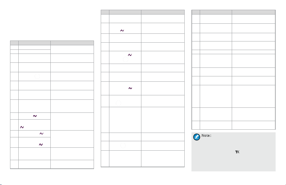
Instructional Icons
Icon Description
Note
Indicates references that can further
describe the related topics.
Indicates situations that could cause
Caution
data loss or equipment damage.
Indicates functions that are
available on digital channel only.
indicates functions that are
available on analog channel only.
Functions marked with no function
icons are available on both analog
and digital channels.
Key Operation
Operation Denition
Short press To press a key and release it quickly.
Long press
Hold
To press a key and remain holding
it down for a predefined period (2
seconds by default).
To press a key and remain holding it
down.
Checking Items in the Package
Please unpack carefully and check that all items
listed below are received. If any item is missing or
damaged, please contact your local dealer.
Radio Unit Battery Antenna Strap
Product Introduction
This section introduces the mechanical structure and
the programmable features of this radio.
Product Controls
Notational Conventions
Convention Description
The quotation marks enclose
“ ”
the name of a software interface
element. For example, click “OK”.
The text in boldface denotes the
Bold
name of a hardware button. For
example, press the PTT key.
The symbol directs you to access
a multi-level menu. For example, to
->
select “New” from the “File” menu,
we will describe it as follows: File ->
New.
Charger Power Adapter Documentation
Quick Reference Guide
Note: The fr equen cy band is marked on the
label of a ntenn a; if not, pleas e refer t o the
label on the terminal for frequency band
information.
No. Part Name No. Part Name
1 Accessory Jack 11 Up Key
Radio On-Off/Volume
2
Control Knob
3 OK/Menu Key 13 P2
4 P1 14 Down Key
5 Numeric Keypad 15 SK1 (Side Key)
6 Antenna 16 PTT Key
Channel Selector
7
Knob
8 LED 18 Speaker
9 LCD Display 19 Microphone 2
10 Microphone 1 20 Battery
12 Back Key
17 TK (Top Key)
2
Programmable Keys
For enhanced convenience, you may request your
dealer to program the keys SK1, TK, P1 and P2 as
shortcuts to the functions listed below: For detailed
introductions of the functions, please go to the
chapter "Functions and Operations”.
No. Shortcut Key Function
1 Zone Up
2 Zone Down
3 Keypad Lock
4 Contact List
5 Message
6 Call Logs
7 Adjust Power Level
8 Talk Around
9 Monitor
Monitor Momentary
10
11 Squelch Off
Squelch Off
12
Momentary
13 Home Screen
14 Scan
3
To select a desired zone
quickly.
To lock or unlock the
keypad quickly.
To access the menu
“Contact List” quickly.
To access the menu
“Message” quickly.
To access the menu “Call
Logs” quickly.
To adjust power level
quickly.
To enable or disable
the Talk Around feature
quickly.
To enable or disable the
Monitor feature quickly.
To enable or disable the
Squelch feature quickly.
To quickly return to the
previous menu or home
screen.
To enable or disable the
Scan feature quickly.
No. Shortcut Key Function
Nuisance
15
Temporary Delete
Adjust Squelch
16
Level
Battery Power
17
Indicator
18 Man Down
Scrambler /
19
Encrypt
20 Lone Worker
One Touch Call 1 –
21
5
22 Status List
Telemetry Button 1
23
– 3
24 DTMF Keypad
25 Phone List
26 Roam
27 Priority Interrupt
To temporarily ignore
unwanted channel activity.
To access the menu
“Squelch Level” quickly.
To check the battery
strength promptly.
To activate or deactivate
the Man Down function.
To enable or disable the
Scrambler or Encryption
feature quickly.
To enable or disable Lone
Worker feature quickly.
To make appropriate
services quickly.
To access the menu
“Status List” quickly (for
5-Tone).
To monitor remote
equipment.
To enable or disable the
DTMF keypad quickly.
With the DTMF keypad,
you can enter a number
via the keypad to make a
phone call.
To access the menu
“Phone List” quickly.
To enable or disable the
Roam feature quickly.
To terminate the ongoing
activity on the current
channel, so as to initiate a
new call or data service.
No. Shortcut Key Function
28 VOX
29 BT
30 GPS Report
31 Option Board
32 Morse Code To send Morse code.
Receiving
33
Vibration
34 Emergency On
35 Emergency Off
Preset Channel 1
36
– 4
37 LQO
38 Covert Mode
N o t e:
●Long and short press of a key can be
assigned with different functions by your
dealer.
●Short press of the TK key is assigned with
the Emergency On feature, long press
assigned with the Emergency Off feature.
You can also assign it with other features
via your dealer.
To enable or disable the
VOX feature quickly.
To enable or disable the
BT feature quickly.
To upload GPS data to the
system immediately.
To enable or disable the
Option Board function.
To enable or disable
the Receiving Vibration
feature quickly.
To activate the emergency
alarm.
To deactivate the
emergency alarm.
To switch the channel
quickly. The target
channel, preset by the
dealer, is a channel from
any zone.
To enable or disable LQO
(Loudness and Quality
Optimizer) quickly.
To enable or disable the
Covert mode quickly.
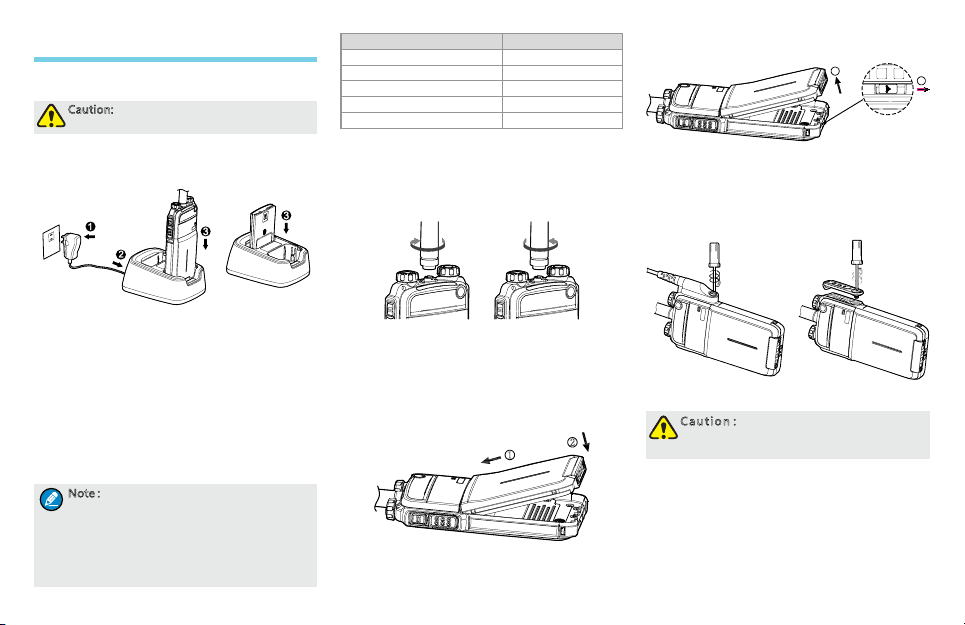
Before Use
Charging the Battery
Caution: Make sure the radio is powered off
during charging.
Use only the charger and battery specied by Hytera.
Charger LED can indicate the charging process. The
following gure shows steps for charging.
1. Connect the power adapter to AC socket. See arrow ①.
2. Plug the power adapter into the rear jack of the
charger. See arrow ②.
3. Place the radio with the battery attached, or the
battery alone, into the charger.
During charging, the LED on the charger will indicate
the charging status. Charging begins when the
charger LED glows red. When charging is complete,
the charger LED glows green.
See the following table for details.
N o t e:
●To achieve optimal battery performance,
please charge the battery for 3 hours
before initial use.
●Be sure to read the Safety Information
Booklet, to get necessary battery safety
information.
The LED ashes red slowly. Standby (no load)
The LED glows red. Charging
The LED glows orange. 90% charged
The LED glows green. Fully charged
The LED ashes red rapidly. Failure
LED Charging Status
Assembling Accessories
Assembling the Antenna
Turn the antenna clockwise to fasten it.
To remove the antenna, rotate it counter-clockwise.
Assembling the Battery
1. Insert the battery into top of the radio. See arrow
.
①
2. Slightly press the bottom of the battery until a
click is heard. See arrow ②.
1
To remove the battery, turn off the radio rst. Slide
the lock in the direction (see arrow ①) to loosen the
2
battery latch, then raise the battery latch and remove
the battery (see arrow ②).
2
Assembling the Audio Accessory
1. Open the accessory jack cover as the arrow
shows.
2. Align the plug with the accessory jack.
3. Tighten the screw on the plug.
To remove the accessory, loosen the screw rst.
Caution:Please att ach th e acces sor y
properly; otherwise, waterproof
perf orman ce of the r adio may get affected.
1
4
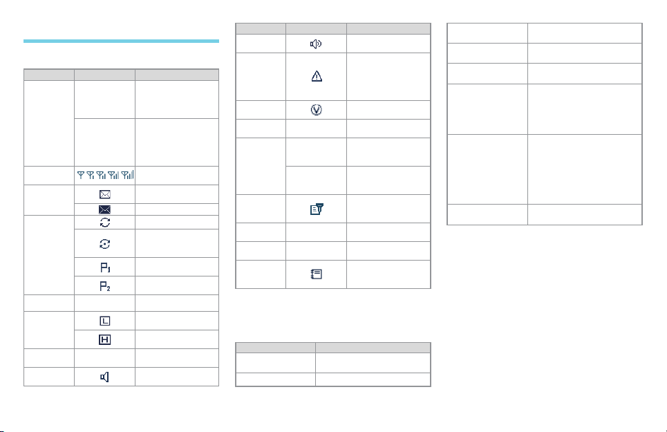
Status Indication
LCD Icon
Icon Name Icon Radio Status
Operation
Mode Icon
RSSI Icon
Message
Icon
Scan Icon
Roam Icon The radio is roaming.
Tx Power
Icon
Battery
Power Icon
Monitor Icon
5
DM
RM
Direct Mode: Under
this mode, radios
communicate with
each other directly.
Repeater Mode:
Under this mode,
radios communicate
with each other via a
repeater.
More bars indicate
better signal strength.
New message/unread
message
InBox is full.
The radio is scanning.
Scanning pauses
on a non-priority
channel.
Scanning pauses on
Priority Channel 1.
Scanning pauses on
Priority Channel 2.
Low Tx power for the
current channel
High Tx power for the
current channel
More bars indicate
more battery power.
The Monitor feature
is active.
Icon Name Icon Radio Status
Speaker
Icon
Emergency
Icon
VOX Icon
Accessory
Icon
GPS Icon
Scrambler/
Encrypt Icon
Missed Call
Icon
DTMF
Keypad Icon
Work Order
Icon
The speaker is
unmuted.
The Emergency mode
(other than secret
emergency) is active
or an emergency
alarm is received.
The VOX feature is
active.
An accessory is
connected.
The GPS feature is
active, and valid GPS
data is received.
The GPS feature is
active, but no valid
GPS data is received.
The Scrambler/
Encrypt feature is
active.
You have missed
call(s).
The DTMF keypad is
enabled.
One or more new
work orders are
received.
LED Indicator
The top LED will help you easily identify the current
radio status.
LED Indication Radio Status
The LED ashes
green
The LED glows red Transmitting
Powering on
The LED glows
green
The LED ashes
orange slowly
The LED ashes
orange rapidly
The LED glows
orange
The LED glows
blue and then turns
to ash once every
3s.
The LED ashes
blue once every 2s.
Receiving
Scanning
Emergency
No voice is being transmitted
or received on the channel
after a call is established.
Within such period, you can
hold the PTT key to talk.
The LED glows blue when
the BT is being powered on,
and turns to ash once every
3s when the BT is powered
on without any BT device
connected.
BT devices are connected.

Menu Navigation
Main Menu
Contact Message
Call
Logs
Settings
Zone
Accesso
ries
Phone
Contact
List
New
Contact
New
Msg
Quick
Text
OutBox
Drafts
InBox
Outgoing
Incoming
Phone
List
Missed
Manual
Dial
Keypad Lock
DTMF
Keypad
Roam
Power Level
Radio
Set
Backlight
Device
Info
Brightness
Language
Encrypt
Tone
LED
Rent
LQO
VOX
Lone Worker
Priority
Covert Mode
Man Down
GPS
Scan
List
Scan
Manual
Dial
Scan
On/Off
Scramble
Vibration
Password
Select Locked Key
Program
ming
Frequen
cy
Slot
Color
Code
Bluetoot
h
Basic Operations
The following gure shows an overall menu structure of the radio. You can customize these menus as per your
requirements via your dealer.
Press the Menu key to enter the main menu, then enter the submenus or options via the Up/Down key and
press the OK key to complete the conguration. The introductions of the menu operations mainly introduce the
path to the menus.
This radio supports menu reset function, that is, if you do not operate the menu for a predened time period,
the radio will automatically return to the home screen. However, you can modify the reset time or cancel the
reset feature via your dealer.
Powering On/Off
Rotate the Radio On-Off/Volume Control knob
clockwise/counter-clockwise until a click is heard to
turn the radio on/off.
Adjusting the Volume
After turning the radio on, rotate the Radio On-Off/
Volume Control knob clockwise to increase the call
volume, or counter-clockwise to decrease it.
Selecting a Zone
A zone is a group of channels exhibiting the same
property, and is programmed by your dealer. The
radio supports up to 64 zones, each with a maximum
of 16 channels. You may select a zone through any
BT
of the following methods:
Through menu selection
Go to the menu “Zone”, and use the Up/Down
key to select your desired zone.
Through the function keys
You may quickly toggle to your desired zone
by pressing the programmed Zone Up or Zone
Down key.
Selecting a Channel
After turning the radio on, rotate the Channel
Selector knob to select a desired channel. You can
also switch to the designated channel by pressing the
programmed Preset Channel key.
If the Channel Notify function is active, you will hear
6

the corresponding channel number when switching to
any channel.
Switching the Channel Mode
Each channel can be programmed as either analog
channel or digital channel. If the current zone
includes both analog and digital channels, you may
switch between digital and analog channels.
Locking/Unlocking the Keypad
When the keypad is not in use, you can lock the
keypad to prevent accidental keypad operation. The
following methods are available for you to lock or
unlock the keypad:
Key Combination
Use “OK+ ” to lock or unlock the keypad.
Programmable Key
Press the programmed Keypad Lock key to lock
or unlock the keypad.
Menu Selection
Go to “Settings -> Radio Set -> Keypad Lock”,
and then select “Enable” or “Disable”.
»Enable: The keypad will be locked
automatically if no operation is made within
the Keypad Lock Time, which can be
congured via the Up/Down key (range: 5 –
60s).
»Disable: The keypad will not be locked
automatically. However, you can lock or
unlock the keypad via the key combination or
Keypad Lock key mentioned above.
7
N o t e:Exc ept P1 and P2, other keys on t he
keypad are lockable by default. Besides,
you can decide ot her keys and knobs to be
locked via the menu “Settings -> Radio
Set -> Selec t Locke d Key”. The Select
Locked Key includes the following options:
TK, Channel Selector knob, P1, P2, SK1 and
Volume knob.
Using the BT Devices
BT is a kind of wireless technology that supports
short-distance (generally within 10m) communications
and information exchange between devices such as
mobile phones, PDAs, wireless earpieces, laptops,
etc.
Caution:
●For optimal communication quality, it
is recommended to use our specified
BT devices: the wireless earpiece and
wireless finger PTT (find the device model
number in “Optional Accessories”
chapter). To learn the detailed functions
and operations of the devices, refer to
the corresponding manual.
●If you use other company’s BT earpiece,
you will need to use it with our specified
wireless finger PTT, otherwise, you will
not be able to transmit via this earpiece.
For clear voice communications, when using the
devices, please place the radio as required below.
When the radio is worn, put it and the devices
on the same side with the radio’s front case (the
case with the LCD) outwards.
When the radio is not worn, keep it within 2m
away from the devices with its front case towards
the devices.
Connect the BT devices to the radio in the following
steps:
1. Turn on the radio.
2. Activate the BT feature by pressing the pro-
grammed BT key or via the menu “Accessories
-> BT -> On/Off”.
When the LED glows blue and then ashes blue
once every 3s, it indicates the BT feature of the
radio is enabled.
Note: The wireless PTT and wireless earpiece
must be searched and connected separately.
As the op erati ons on th em are th e same , we
take the w ireless PT T as an example below.
3. Turn on the BT device and enter the pairing.
Refer to the corresponding accessory manual for
the operations.
4. Go to menu “Accessories -> BT -> Paired
Devices” and select “Search PTT” to start
searching.
5. When the wireless PTT is found, enter “Devices
List” to find the alias of the PTT, and select
“Connect”.
When the connection is done, the prompt
”Connect Success!” will be displayed on the LCD,
and the LED will ash blue once every 2s.

Call
To ensure optimal volume of the receiving radio,
hold the palm microphone approximately 2.5 to 5
centimeters away from your mouth.
Private Call
Initiating a Call
You may transmit a private call through any of the
following methods. When the radio transmits a
private call, the icon will appear on the LCD.
Transmitting a call to the preset contact
In the home screen, hold the PTT key to transmit a
private call to the private call contact preset for the
current channel.
Note: Your dealer may preset a contact for
each dig ital channe l. The pr eset co ntac t
could be a p rivate call contac t, a gro up call
contact or an all call co ntac t.
Transmitting a call through Contact List or Call
Logs
1. Go to “Contact -> Contact List”, or go to “Call
Logs” and access the Outgoing/Incoming/Missed
list.
2. Use the Up/Down key to select the private call
contact you want to call.
3. Hold the PTT key to transmit the private call.
Through manual input
1. Go to “Contact -> Manual Dial”.
2. Input a private call contact you want to call.
3. Hold the PTT key to transmit the private call.
N o t e:
●If your radio supports both Private Call
Manual Dial and Group Call Manual
Dial, you can switch between them by
pressing . The LCD will display the
appropriate ID.
●If the Default Numeric Key Selection
feature is enabled by your dealer, you
can enter a private call number in the
home screen, and then hold the PTT key
to transmit the private call. However, if
the DTMF keypad is enabled, the number
entered in the home screen is a phone
number. You can dial the phone number
through the menu “Manual Dial” only.
Receiving and Responding to a Call
When a private call is received, your radio will display
the icon .
You may hold the PTT key within the preset time
period to call back. If you do not respond to it, your
radio will provide appropriate indications.
N o t e:
●If the Display Missed Call feature is
enabled by your dealer, your radio will
display the missed call icons and
●If the Display Missed Call feature is not
enabled, your radio will display the
missed call icon only.
.
Group Call
Initiating a Call
You may transmit a group call through any of the
following methods. When the radio transmits a group
call, the icon will appear.
Transmitting a call to the preset contact
In the home screen, hold the PTT key to transmit
a group call to the group call contact preset for the
current channel.
Transmitting a call through Contact List
1. Go to “Contact -> Contact List”.
2. Use the Up/Down key to select the group call
contact you want to call.
3. Hold the PTT key to transmit the group call.
Through manual input
1. Go to “Contact -> Manual Dial”.
2. Input a group call contact you want to call.
3. Hold the PTT key to transmit the call.
N o t e:
●If your radio supports both Private Call
Manual Dial and Group Call Manual
Dial, you can switch between them by
pressing . The LCD will display the
appropriate ID.
●If the Default Numeric Key Selection
feature is enabled by your dealer, you can
enter a group call number in the home
screen, and then hold the PTT key to
transmit the call. However, if the DTMF
keypad is enabled, the number entered in
the home screen is a phone number. You
can dial the group call number through
the menu “Manual Dial” only.
Receiving and Responding to a Call
When a group call is received, your radio will display
the icon .
You may hold the PTT key within the preset time
period to call back.
8

All Call
Initiating a Call
Two methods are available for transmitting an all call:
transmitting a call to the preset contact; transmitting a
call through Contact List. They are the same as those
in the foregoing “Transmitting a Group Call”. When
transmitting an all call, the icon will appear.
Note: You can tra nsmit a n all cal l only when
it is enabled by yo ur deal er.
Receiving a Call
When an all call is received, your radio will display
the icon .
Note: You cannot respo nd to a rec eived all
call.
Calls on Analog Channels
To transmit a call on the analog channel, hold the
PTT key, and speak into the microphone. To receive,
release the PTT key.
Sending Morse codes
Morse code is a method of transmitting textual
information as a series of on-off tones, lights or clicks
that can be understood by the receiving party. It is
usually used for secret communication.
When pressing the PTT key, press the programmed
Morse Code key to transmit a Morse code. Release
the Morse Code key to stop the transmission.
Different length of the press makes different Morse
9
codes. You can transmit the signals with Morse code
combination. If the Signaling Side Tone is enabled,
both the transmitting and receiving parties will hear
the tone during the transmission of the Morse code.
Receiving Vibration
When receiving an audio signal, the radio will keep
vibrating until receiving ends, with the received voice
muted.
You can enable or disable this feature via the
programmed Receiving Vibration key.
Phone
If the repeater is connected with a PSTN gateway,
the radio can communicate with the phone via it.
Initiating a Call
1. Access the phone system.
Live Dial: Hold the PTT key, and enter the access
code with keypad. Then release the PTT key. The
radio beeps and displays the dialing information.
When the phone system is accessed successfully,
the radio goes to the DTMF keypad mode.
Buffer Dial:
Enter the DTMF keypad mode. The following
methods are available to enter this mode.
»Go to “Main Menu -> Phone –> Manual Dial”
to enter the DTMF keypad mode.
»Enable the DTMF keypad by pressing DTMF
Keypad key or going to “Phone -> DTMF
Keypad” menu. Then the number entered via
the numeric keypad in the home screen is the
DTMF code.
Access the phone system: Enter the access code
via the keypad and then press the PTT key. The
radio beeps and displays the dialing information.
When the phone system is accessed successfully,
the radio goes to the DTMF keypad mode again.
2. Make the phone call.
Live Dial: Hold the PTT key and enter the phone
number via the keypad. Release the PTT key
after the complete number is entered.
Buffer Dial: Enter the phone number via the
keypad and then hold the PTT key.
Note: Whichever dialing method you take,
now you ca n press the Back key and s elec t
the cont act v ia “Phon e -> Phone List”
menu, and then press the PTT key.
3. After the call is established, you can hold the PTT
key to talk, and release it to listen.
To end the call, you can send the de-access code
(the input method is the same as that for the
access code) to exit the phone system.
If the phone is hung up, the call will be ended and
the phone system will be exited too.
Receiving a Call
Upon the receipt of a phone call, the radio will display
icon or .
You may hold the PTT key within the preset time
period to call back. If you do not respond to it,
your radio will provide appropriate indications. The
indication information is the same as that for the
private call.
Time-out Timer (TOT)
TOT aims to prevent any user from occupying a

channel for an extended period. If the preset time
expires, the radio will automatically terminate
transmission and keep beeping. To stop beeping,
please release the PTT key. You must wait for a
certain time (preset by your dealer) to initiate another
transmission.
If the pre-alert function is set by your dealer, your
radio will alert you to the TOT expiration in advance.
Note: This fe ature i s null in Em ergency
mode.
Busy Channel Lockout
If enabled (via the programming software), this
feature can prevent your radio interfering with other
transmitting terminals on the same channel. If you
hold the PTT key while the channel is in use, your
radio will keep beeping and display “Channel Busy!”,
alerting you to transmission prohibition. When the
channel is free, you can press and hold the PTT key
to transmit.
Pseudo Trunking
This feature can be enabled via the programming
software. If your radio operates on a channel with
this feature enabled and one time slot is already
occupied, it can transmit and receive on the other
free slot.
Functions and Operations
This manual introduces all features of this radio. You
can learn its available functions from your dealer.
Home Screen
The feature allows you to quickly return to the
previous menu or the home screen.
In the editing screen, press the P2 key, and the radio
exits the screen and returns to the previous menu
immediately; in other screens, press this key and the
radio returns to the home screen immediately.
Managing the Contacts
You can have management of your contacts via the
menu “Contact” in the radio.
Contact List
You can save up to 512 entries of private call contact
information in the list. To access this menu, select
“Contact -> Contact List” or press the shortcut key for
Contact List.
Control Services
You can send to a private call contact the following
commands: Alert Call, Radio Check, Remote Monitor,
Radio Enable or Radio Disable. See the “Manual
Dial” below for details.
Editing a Contact
You can edit the number and alias of each private call
contact.
Viewing a Contact
You can view details of each contact.
Deleting a Contact
You can delete a private call contact. However,
please note that you can not delete the contact when
there is only one entry left in the list or the private call
contact preset on the currently used channel.
New Contact
You can add a private call contact to the contact
list. The number and alias of each contact must
be unique, and the available number range is 1 –
16776415.
Note:
●You can press the key to switch the
input method when editing the alias.
●Besides adding new contacts, you can
also save the unidentified numbers from
the Call Logs into the contact list.
Manual Dial
You can manually input the required ID for calling. On
a digital channel, if your radio supports both private
call and group call, you can switch between them by
pressing . The LCD will display appropriate ID.
For a private call ID, you can select any of the
following options:
Supplementary
Service
Alert Call
Description
You can send an alert call to a
private call contact. The called
party will see the alert and can
call you back.
10

You can send a Radio Check
command to a private call
Radio Check
Remote Monitor
Radio Enable
Radio Disable
contact, so as to conrm whether
it is powered on or running on the
current channel without disturbing
it.
You can enable the microphone of
a private call contact, and monitor
its activities or background voice
remotely.
You can enable the radio of a
private call contact remotely and
allow it to be used normally.
You can disable the radio of a
private call contact remotely and
disallow it to be used normally.
The disabled radio can be
monitored remotely, but other
features will be locked out. It can
only be revived by reprogramming
through the CPS or through the
Radio Enable command.
Message
Sending a message
1. Go to “Message -> New Msg”.
2. After editing the text, press the OK key.
3. Select the contact or input the contact number
manually.
4. Press the OK key to send the message. When
the message is sent successfully, the radio will
display “Send Success!” on the LCD.
You can send the Quick Text or forward the message
saved in the InBox, OutBox or Drafts. See the
detailed introductions of the submenus of Message
respectively.
11
New Msg
You can create a new text message (256 characters
at most) and save it to Drafts, or send it to a private
call contact or a group call contact.
Quick Text
Under this option there are some text messages
(25 entries at most) preset by your dealer. You can
choose to edit and send any entry.
InBox
The radio saves the received messages into the
InBox and gives every message a corresponding
icon to show whether it is read.
: Read message
: Unread message
The InBox can save up to 20 received messages.
When it is full, the icon will appear, and the
earliest message will be overwritten by the latest one
automatically.
For each message, you can choose to perform
any of these operations: Reply, Forward, View
Details and Delete.
To delete all messages in the InBox, select
“Message -> Inbox -> Delete All”.
OutBox
The following icons will appear to indicate whether
the message is sent successfully.
: Message is sent successfully.
: Failed to send message
The radio can save up to 20 sent messages. When
the OutBox is full, no icon will appear on LCD to
alert you. In addition, the earliest message will be
overwritten by the latest one automatically.
For each message, you can choose to perform
any of these operations: Resend, Forward, View
Details and Delete.
To delete all messages in the OutBox, select
“Message -> Outbox -> Delete All”.
Drafts
The Drafts can save up to 20 draft messages.
When the Drafts is full, the earliest message will be
overwritten by the latest one automatically.
For each message, you can choose to perform any
of these operations: Send, Save and Delete.
After the message in the Drafts is sent, it will be
removed from the Drafts and be saved to the
Outbox.
To delete all messages in the Drafts, select
“Message -> Drafts -> Delete All”.
Work Orders
This feature is programmed by the dealer. It enables
the radio to receive work orders from the third party
and reply it with the current work status. Please
contact your dealer for details.
Call Logs
The radio can save up to 10 private call entries in the
Outgoing/Incoming/Missed list respectively. When
the Outgoing/Incoming/Missed list is full, the earliest
entry will be overwritten by latest one automatically.
You can press the Menu key to enter “Main Menu
-> Call Logs” menu, or enter the “Call Logs” menu

directly via the shortcut key for Call Logs.
After accessing a list and selecting an entry, you can
perform any of these operations: hold the PTT key
to initiate a call; add it to Contact List; or delete it. To
delete all entries in the Outgoing/Incoming/Missed
list at a time, select “Call Logs -> Outgoing/Incoming/
Missed -> Delete All”.
VOX
This feature allows you to transmit the voice with no
need to press PTT.
When VOX is enabled, the icon will appear.
Enabling or disabling the VOX Feature
Press the programmed VOX key to toggle the VOX
function on or off.
You can also toggle it on or off via the “Settings ->
Radio Set -> VOX” menu.
Adjusting the VOX Gain Level
You can set the sensitivity of microphone
transmission via the “Settings -> Radio Set -> VOX
-> Gain Level” menu. The higher gain value indicates
lower sensitivity.
Internal: the VOX transmission sensitivity of
internal microphone
External: the VOX transmission sensitivity of
external microphone
Caution: Please ad just th e VOX Gain Le vel
prope rly on yo ur act ual requirem ents .
MIC AGC
This feature can be enabled via the programming
software. Your radio will control the audio gain
during transmission, providing improved audio with
appropriate volume for the receiving radio.
Audio Feedback Suppression
This feature can be enabled via the programming
software. It can weaken the noise caused by short-
distance communication, so as to improve the voice
quality.
LQO
This feature enables the radio to adjust the audio
quality automatically in standby mode to t different
using environments, as well as making the heard
voice clear.
You can enable or disable the LQO feature by
pressing the programmed LQO key or via the menu
“Settings -> Radio Set -> LQO”.
Rent
Your dealer can rent the radio to you. If you are
renting the radio, when the rental expires, you are not
allowed to go on using the radio.
You can check the remaining rental time of the radio
via the menu “Settings -> Radio Set -> Rent -> Rent
Query”.
If the Rent Pre-Alert feature is enabled, the radio will
give a tone periodically to remind you how much time
is left for the rental.
Scan
The Scan feature allows you to listen to
communication activities on other channels so that
you can keep a close track of your team members.
Operation
To enable the feature, you can select “On” from
the menu “Scan”, press the programmed Scan
key in the home screen, or switch to a channel
for which the Auto Scan feature is enabled via the
programming software.
After the feature is enabled, your radio will scan
according to the scan list set for the channel on
which scanning starts. The scanning process is
as follows:
»During scanning, the LCD displays the icon
, and the LED ashes orange slowly.
»When activities are detected on a channel,
the radio will stay on the channel to receive
current activities. If your radio stays on a
non-priority channel, the LCD will display the
icon ; if on Priority Channel 1 or Priority
Channel 2, the LCD will display the icon or
accordingly.
If you don’t want to hear activities on the
channel, press the programmed Nuisance
Temporary Delete key to remove the channel
from the scan list temporarily.
If you want to continue staying on the
channel, press the programmed Monitor or
Squelch Off key during scan stay.
To exit the scanning process, you can select
“Off” from the menu “Scan”, or press the
programmed Scan key again.
Scan Set
You can request your dealer to create a scan list for
each channel. Each list may contain 32 channels at
most (either digital channel or analog channel is OK).
12

You can have the following conguration to the Scan
List: Go to “Scan -> Scan List”.
Adding a Channel
To include a new channel into the active scan list.
Editing Priority Channel
To set the selected channel as a priority channel
or non-priority channel. If you are interested in
activities on a channel, you can set it as a priority
channel, which will be scanned more frequently
than a non-priority channel.
Each scan list may contain two priority channels
at most.
indicates Priority Channel 1, and
indicates Priority Channel 2.
Deleting a Channel
To remove a channel from the active scan list.
However, the rst channel in the list can not be
deleted.
Roam
This feature allows the radio to communicate
between sites in the IP Multi-site Connect system.
If enabled, the radio can communicate via any site
in the IP Multi-site Connect system, thus ensuring
seamless communication in the system.
Operation:
Enable or disable Roam feature via the “Roam”
menu.
Press the programmed Roam key to enable or
disable the feature.
Adjust Power Level
With this feature, you may switch power levels
13
quickly. Generally, we recommend you to adopt low
power for battery saving. However, if you cannot
communicate with radios located at a distant place
with low power, please select high power.
Press the programmed Adjust Power Level key to
switch between high power and low power (from low
power to high power: a high-pitched tone sounds;
from high power to low power: a low-pitched tone
sounds).
Note: Power le vel sho uld be se t for eac h
channel respectively.
Talk Around
You can continue to communicate in DM mode by
pressing the programmed Talk Around key, when
your repeater malfunctions, or when your radio is out
of the repeater’s range but within talking range of
other radios.
Press the programmed Talk Around key to enable
the feature (a high-pitched tone sounds). To disable
the feature, press this key again (a low-pitched tone
sounds).
Monitor
To adjust match conditions for signal receiving, you
can enable the Monitor feature.
Press the programmed Monitor key to enable the
feature, and the radio displays icon . To disable
the feature, press this key again.
Hold the programmed Monitor Momentary key
to enable the feature, and the radio displays icon
. To disable the feature, release this key.
Squelch Off
If the Squelch Off feature is enabled, the speaker will
keep unmuted no matter whether carrier is present.
Press the programmed Squelch Off key to
enable the feature. Then the radio displays the
icon and sounds background noise. To
disable the feature, press this key again.
Hold the programmed Squelch Off Momentary
key to enable the feature. Then the radio displays
the icon and sounds background noise. To
disable the feature, release this key.
Adjust Squelch Level
This feature allows you to adjust the squelch
threshold required for the radio to be unmuted.
Generally, the higher squelch level requires stronger
signal for the radio to be unmuted. If the squelch
level is set to “Open”, the speaker will keep unmuted
irrespective of the satisfaction of decoding conditions.
Press the programmed Adjust Squelch Level key to
switch among “Tight”, “Normal” and “Open”. You can
also switch among these levels via the menu “Settings
-> Squelch Level”.
When switching from “Tight” to “Open”, a low-pitched
tone sounds followed by the background noise; from
“Open” to “Normal”, a high-pitched tone sounds with
the background noise fading; from “Normal” to “Tight”,
a high-pitched tone sounds.
One Touch Call
You can request your dealer to set the One Touch
Call key. By pressing the programmed key, you can
make corresponding services detailed as below:

Services on the analog channel: to send calls to
the 5-Tone or 2-Tone contact.
Services on the digital channel:
»To send group calls or messages to the group
call contact.
»To send private calls, messages or make
control services to the private call contact.
The control services contain: Alert Call, Radio
Check, Remote Monitor, Radio Enable or
Radio Disable.
Alert Call
You can send an alert call to a private call
contact. The called party will see the alert and
can call you back.
Radio Check
You can send a Radio Check command to a
private call contact, so as to conrm whether
it is powered on or running on the current
channel without disturbing it.
Remote Monitor
You can enable the microphone of a private
call contact, and monitor its activities or
background voice remotely.
Radio Enable
You can enable the radio of a private call
contact remotely and allow it to be used
normally.
Radio Disable
You can disable the radio of a private call
contact remotely and disallow it to be used
normally.
Operation:
Service Operation
To send private calls/group
calls on the digital channel.
To send calls on the analog
channel.
Sending a Message
To make control services
on the digital channel.
Press the One
Touch Call key and
then hold the PTT
key.
Press the One
Touch Call key.
Telemetry
This feature allows you to remotely supervise the
device connected with a radio. With this feature, you
can control the device and view its status in the case
that you are away from the device.
The method for supervising the device is
programmable by your dealer. The available methods
are:
To supervise the device via the radio
If a device is connected with a radio, you can
use another radio to supervise the device. All
the radios involved should be configured with
the Telemetry feature. For example, the dealer
enables the Telemetry feature for both Radio A
and Radio B, and assigns the Telemetry feature
to the SK1 key on Radio A. To supervise the
Device C, connect it with Radio B, and press the
SK1 key on Radio A.
To supervise the device via a third-party software
If the Telemetry feature is enabled for the radio
by your dealer, you can supervise the device
connected with the radio via third-party software.
Priority Interrupt
Manual Priority Interrupt
You can have the priority of interruption by pressing
the programmed Priority Interrupt key. By pressing
this key, you can terminate the ongoing activity (a
call, Call Hold Time or remote monitoring) on the
current channel, so as to initiate a new call or data
service.
Call Hold Time: the duration the radio stays at in-call
status after the end of the call. There are two types:
Group Call Hold Time and Private Call Hold Time.
Within the time, you can hold the PTT key to directly
call back.
Auto Priority Interrupt
The Auto Priority Interrupt is enabled by the dealer.
It is designed to ensure the priority given to the
specified services. Such services will trigger the
interruption automatically.
Emergency Priority Interrupt
This function is designed for users to report an
emergency alarm in time. Carrying this function
would interrupt the active call on the current channel.
To carry out the function, any of the following ways is
available:
Press the programmed Emergency On key.
Hold the PTT key in Emergency mode.
Auto Emergency Call
Call Back Priority Interrupt
With the feature enabled, you can hold the PTT
key to interrupt a receiving call and call back. For
example, user A is receiving a call from user B. This
14

function allows user A to interrupt the call and talk
back to user B by pressing the PTT key.
Message Priority Interrupt
During a call on the channel, this function allows you
to send a short message which will also interrupt the
call.
Radio Disable Priority Interrupt
During a call on the channel, this function allows
you to send a radio disabling command which will
also interrupt the call. The disabled radio can be
monitored remotely, but other features will be invalid.
It can only be revived by reprogramming through the
CPS or through the revive command.
All Call Priority Interrupt
During a call on the channel, this function allows you
to transmit an all call which will interrupt the ongoing
call.
Emer Alarm
In case of an emergency, you can use the feature to
ask for help from your companion or control center.
The emergency alarm has the highest priority. You
can make emergency operation even when your
radio is transmitting or receiving.
Caution:
Any of the t wo situations belo w will occur
when the emergency alarm initiator exits
the Emergency mode:
●The initiator presses the programmed
Emergency Off key or Power Off key to
exit the Emergency mode.
●When exiting this mode in other ways
(as introduced below), the radio can only
15
exit the emergency alarm on the current
channel temporarily, and will continue
to give the alarm when it returns to
this channel; moreover, when the radio
switches to another channel which is also
designed with the Emergency feature, it
will give an alarm on that channel, too.
The Emergency feature is enabled by your dealer.
Before use, you may need to know the following
concepts.
Emergency Type
Different types will have different indications:
Emergency
Type
Siren Only
Regular
Silent
Silent with
Voice
In Emergency mode, the radio will
sound shrill alarm tone and display
icon .
In Emergency mode, the radio will
give audible and visible indication.
In Emergency mode, the radio won't
give any audible or visible indication.
In Emergency mode, the radio won’t
give any audible or visible indication,
but will receive voice ACK from
the companion or control center
automatically.
Description
Emergency ID Type
Your radio supports three Emergency ID types. You
can select one of them via your dealer:
Emergency
ID Type
None
No signaling is used when the radio
sends alarm information.
Description
HDC1200
5-Tone
HDC1200 signaling is used when
the radio sends alarm information.
5-Tone signaling is used when the
radio sends alarm information.
Emergency Mode
Except “Siren Only”, other emergency types support
the following three Emergency modes. You can select
one of them via your dealer (Note: For the following
operation methods, we take the “Regular” type as an
example).
Emergency
Mode
Alarm
Alarm with
Call
In this mode, you can send alarm
information to your companion
or control center by pressing the
programmed Emergency On key, but
you cannot talk with them.
In this mode, you can send alarm
information by pressing the
programmed Emergency On key.
When the icon appears, you
can hold the PTT key to speak into
the microphone. Your voice and
background noise to be transmitted
automatically.
Description
Note: If the Alarm with Call To
Follow feature is enabled by your
dealer, you can speak into the
microphone without holding the
PTT key.

Emergency
Mode
Emergency
Call
In this mode, press the programmed
Emergency On key to go to the
Revert Channel, and you can hold the
PTT key to speak into the microphone
when the icon appears. Your
voice and background noise to be
transmitted automatically.
Description
Note: If the Alarm with Call To
Follow feature is enabled by your
dealer, you can speak into the
microphone without holding the
PTT key.
This mode will be unavailable
when the Emergency ID is not
sent or 5-Tone Emergency ID is
sent.
Operation Methods for Analog Emergency
Alarm (None, 5-Tone & HDC1200)
Initiating an emergency alarm:
Press the programmed Emergency On key to send
alarm information.
None, HDC1200: The radio displays icon
and text information “Sending Alarm”, with the
LED glowing red.
5-Tone: The radio sends the ID first (the icon
and text information “Sending ID” will be
displayed), and then transmits the emergency
alarm (the icon and text information “Sending
Alarm” will be displayed), with the LED glowing
red.
Note: As for None and 5-Tone emergency
ID typ e, if “Lo cal Eme rgency Alarm” is
enabled via th e progr ammin g software, the
radio will give an alarm tone.
Exiting the emergency alarm:
The emergency alarm initiator exits the Emergency
mode in any of the following ways:
Press the programmed Emergency Off key.
Turn the radio off.
Once the Alarm Cycles expire, the radio will exit
the Emergency mode automatically.
Hold the PTT key to exit the Emergency mode.
The radio will transmit the voice on the channel
where the radio operates before entering the
Emergency mode (for HDC1200 only).
The emergency alarm receiving party exits the
Emergency mode in any of the following ways:
None: When an alarm is received, the receiving
party can press any key to exit the emergency
alert. When the alarm initiator exits the
Emergency mode or when the Alarm Cycles
expire, the receiving radio will exit the emergency
alert automatically.
5-Tone: When an alarm is received, the receiving
party can press any key to exit the emergency
alert.
HDC1200: When an alarm is received, the
receiving party can exit the emergency alert by
pressing the TK key within 2s after pressing the
Back key, or switching the channel or powering
off the radio.
Alarm with Call (None, 5-Tone & HDC1200)
Initiating an emergency alarm:
1. Press the programmed Emergency On key to
send alarm information.
»None, HDC1200: The radio displays icon
and text information “Sending Alarm”, with
LED glowing red.
»5-Tone: The radio sends the ID rst (the icon
and text information “Sending ID” will be
displayed), and then transmits the emergency
alarm (the icon and text information
“Sending Alarm” will be displayed), with the
LED glowing red.
Note: As for None and 5-Tone emergency
ID typ e, if “Lo cal Eme rgency Alarm” is
enabled via th e progr ammin g software, the
radio will give an alarm tone.
2. If the Alarm with Call to Follow feature is enabled,
you can speak into the microphone to make an
emergency call when the radio displays the icon
.
3. And when a call is received, the icon
appears.
4. If the preset Voice Cycles expire, you can hold
the PTT key to make the emergency call again
(the radio displays the icon , with the
LED glowing red). After the emergency call is
transmitted, release the PTT key to receive (the
radio displays the icon , with the LED ashing
orange rapidly). And when a call is received, the
icon appears (for HDC1200 only).
Exiting the emergency alarm:
The emergency alarm initiator exits the Emergency
mode in any of the following ways:
Press the programmed Emergency Off key.
Turn the radio off.
16

After the preset Alarm Cycles and Voice Cycles
expire, the radio will exit the Emergency mode
automatically (for None and 5-Tone only).
The emergency alarm receiving party exits the
emergency alarm in any of the following ways:
None: When the alarm is received, the
receiving party can press any key to exit the
emergency alert. When the alarm initiator
exits the Emergency mode or when the Alarm
Cycles expires, the receiving radio will exit the
emergency alert automatically.
5-Tone: When an alarm is received, the receiving
party can press any key to exit the emergency
alert.
HDC1200: When an alarm is received, the
receiving party can exit the emergency alert by
pressing the TK key within 2s after pressing the
Back key, or switching the channel or powering
off the radio.
Call Only (HDC1200)
Initiating an emergency alarm:
Press the programmed Emergency On key to go to
the Emergency Channel, and the radio displays the
icon .
If the Alarm with Call to Follow feature is enabled,
you can speak into the microphone to make an
emergency call when the radio displays the icon
.
And when a call is received, the icon appears.
If the preset Voice Cycles expire, you can hold the
PTT key to make the emergency call again (the radio
displays the icon , with the LED glowing red).
After the emergency call is transmitted, release the
PTT key to receive (the radio displays the icon
17
, with the LED ashing orange rapidly). And when a
call is received, the icon appears.
Exiting the emergency alarm:
To exit the Emergency mode, press the programmed
Emergency Off key or power off the radio.
The emergency receiving party cannot exit the
emergency alert until the initiator exits.
Note: Your dealer may set the numb er of
alarm cycles and alarm duration (None,
5-Tone), number of polite r etries and
impoli te retr ies (HD C1200), number of voice
cycle s, duration of e ach tra nsmis sion an d TX
interval.
Operation Method for Digital Emergency
Emergency Alarm
Initiating an emergency alarm:
Press the programmed Emergency On key to send
alarm information. The radio displays icon and
text information “Sending Alarm”, with LED glowing
red.
Exiting the emergency alarm:
The emergency alarm initiator exits the Emergency
mode in any of the following ways:
Press the programmed Emergency Off key.
Turn the radio off.
Once the Alarm Cycles expire, the radio will exit
the Emergency mode automatically.
When an alarm is received, the receiving party can
exit the emergency alert by pressing the TK key
within 2s after pressing the Back key, or switching
the channel or powering off the radio.
Alarm with Call
Initiating an emergency alarm:
1. Press the programmed Emergency On key to
send alarm information. The radio displays icon
and text information “Sending Alarm”, with
the LED glowing red.
2. Hold the PTT key (the LCD displays the icon
, with the LED glowing red) and speak into
the microphone to transmit the emergency call.
Note: If your de aler has enabled the A larm
with Call To Follow, you can spe ak into the
microphone without pressing the PTT key
when the LCD displ ays the icon . If the
prese t Voice Cycles expire, you ca n hold th e
PTT key to make th e emergenc y call ag ain.
3. And when a call is received, the icon
appears. When the icon appears, you can
hold the PTT key (the icon appears with the
LED glowing red) to speak into the microphone.
Exiting the emergency alarm:
To exit the Emergency mode, press the programmed
Emergency Off key or power off the radio.
When an alarm is received, the receiving party can
exit the emergency alert by pressing the TK key
within 2s after pressing the Back key, or switching
the channel or powering off the radio.
Emergency Call
Initiating an emergency alarm:
1. Press the programmed Emergency On key to
go to the Emergency Channel, and the radio
displays the icon .
2. Hold the PTT key (the icon appears,

with the LED glowing red) and speak into the
microphone to transmit the emergency call.
Note: If your de aler has enabled the A larm
with Call To Follow, you can spe ak into the
microphone without pressing the PTT key
when the icon appears. If the preset
Voice Cycles e xpire , you can h old the PT T
key to make th e emer genc y call again.
3. And when a call is received, the icon
appears. When the icon appears, you can
hold the PTT key (the icon appears with the
LED glowing red) to speak into the microphone.
Exiting the emergency alarm:
To exit the Emergency mode, press the programmed
Emergency Off key or power off the radio.
The emergency receiving party cannot exit the
emergency alert until the initiator exits.
Note: Your dealer may set the numb er of
polite r etries and impolite retri es, num ber of
voice cycles , duration of eac h trans mission
and TX in terval.
Man Down
With the feature enabled, the radio will give a tone
if it tilts to a certain gradient (dened by the dealer)
or stay motionless until the preset period expires.
And the radio will enter the Emergency mode
automatically if you don’t make proper operation on it
within the period when the tone continues. To exit the
Emergency mode, please move it or place it upright.
You can enable or disable the Man Down feature by
pressing the programmed Man Down key or via the
menu “Settings -> Radio Set -> Man Down”.
The radio gives a high-pitched tone when the Man
Down feature is enabled and a low-pitched tone
when the feature is disabled.
Lone Worker
This feature is ideal for persons who work lonely.
If you encounter an incident and cannot operate
your radio within the preset time period, your radio
will alarm automatically to summon help from your
companion.
1. To enable the feature,
Go to “Main Menu -> Settings -> Radio Set ->
Lone Worker” and select “Enable”; or
press the programmed Lone Worker key (a high-
pitched tone sounds); or
turn on the radio if the feature is enabled via the
programming software.
2. If you cannot operate your radio within a preset
response period, your radio will give alerts before
this period expires (dependent on the settings by
your dealer). At this time, you can terminate such
alerts by rotating a knob or pressing a key. When
the response period expires, your radio will trigger
the current emergency system automatically.
3. To disable the feature,
Go to “Main Menu -> Settings -> Radio Set->
Lone Worker” and select “Disable”; or
press the programmed Lone Worker key (a low-
pitched tone sounds).
Note: If the Lone Worker f eature is not
disabled bef ore you r radio is power ed off,
it will re main en abled when powered o n
again.
Covert Mode
When Covert Mode is enabled, the radio will close
any visible indications on it, such as the LED,
Vibration, etc, which are set by your dealer. This
feature is mainly used in special missions.
To enable or disable the Covert mode, you can press
the programmed Covert Mode key, or enter the
menu “Settings -> Radio Set -> Covert Mode”.
Scramble /Encrypt
The Scramble feature can encrypt your audio signals
to prevent eavesdropping. Thus privacy of your
communication is guaranteed.
This Encrypt feature can encrypt your audio signals
to prevent eavesdropping. Thus privacy of your
communication is guaranteed.
On an analog channel, go to “Main Menu -> Set-
tings -> Radio Set -> Scramble” and select “En-
able” or “Disable”; on a digital channel, go to “Main
Menu -> Settings -> Radio Set -> Encrypt” and
select “Enable” or “Disable”.
Press the programmed Scramble/Encrypt key to
enable Scramble or Encrypt on the current channel (a high-pitched tone sounds); press the key
again to disable the feature (a low-pitched tone
sounds).
If the Scramble/Encrypt feature is enabled for a
channel via the programming software, switch
to the channel to enable the feature, or exit the
channel to disable the feature.
Setting of Encryption Key
The radio can contain up to 30 encryption keys. You
can create an encryption key
18

by dening its key ID, alias, length and value, and
then save it. See the details in the following table.
Item Description
Key ID
Key Alias
Key Length
Key Value
Save
The ID consists of numbers only, in the
range of 1 – 255.
The alias can contain 16 characters at
most, composed of Chinese characters,
English letters, numbers and symbols.
Note: The key alias cannot be the
same with the key ID.
This is used to dene the length of the
key.
The value can consist of numbers and
letters A-F (within the predefined key
length).
Save the created key to the key list.
Note: If you need to delete a key,
please request your dealer for
help.
Radio Registration Service
This feature can be enabled via the programming
software. Your radio will automatically register in the
system within a certain period after power-on. Then
it can acquire online information of other radios via
accessing specic servers within the valid registration
period.
GPS
With the enabled GPS feature, when the system
requires GPS information, your radio will upload its
positioning information to the system in the method
set by the dealer.
19
You can upload the GPS information by pressing the
GPS Report key programmed by the dealer.
You can congure GPS via the menu “Accessories ->
GPS” in the radio.
GPS On/Off
This option allows you to set whether to enable the
GPS feature.
Note: Enabling the GP S feature will shorten
the operating time of the battery.
Position
With this option, you can view longitude, latitude,
time, date, speed, altitude and SA (satellite)
information of your radio.
GPS Text Msg
If the GPS feature is enabled, you can send the GPS
text message to your desired contact. To install the
units, please do as follows:
1. Select “GPS Msg”, and press the OK key to
access the menu “Contact List”.
2. Use the Up/Down key to select a desired contact.
3. Press the OK key to send the GPS message to
the selected contact.
Time Zone
You can choose your time zone to correct the
received GPS time. We recommend you to set the
time zone before your initial use of this feature.
You can select a desired time zone via the User
Define method as per your actual needs. The
available time zone options are the same as those
for the PC. For example, if the time at your location
is 5.45 hours earlier than GMT, then you can select
“GMT+5.45” as your time zone.
Radio Set
You can optimize your radio performance by setting it
according to actual needs and your preferences.
Enter “Settings -> Radio Set” menu to set the items
as introduced below:
Power Level
This menu is to set the TX power level to High or
Low. High power can extend the coverage, enabling
you to communicate with farther radios.
Alternatively, you can toggle the power level by
pressing the programmed Adjust Power Level key
in the home screen.
On the LCD, High power is indicated by and Low
power is indicated by .
Language
To set the language used in the radio interface.
Backlight
This menu allows you to set the backlight. Activating
the backlight can illuminate the LCD and the keypad,
so as to facilitate your operation under dim light
conditions.
Off: The backlight will always remain off.
On: The backlight is on all the time.
Timed: If no operation or signal transmission/
receipt occurs within the time preset by the dealer,
the backlight will be turned off automatically.
Brightness
This option allows you to set the display brightness.
You can raise or lower it using the Up/Down key.

LED
This menu allows you to set whether to turn on LED
indicator. Generally, the LED indicator can indicate
TX/RX, Scan/Roam status, Low Battery, etc. The
indications of the LED are set by the dealer.
Tone
You can select the tones on actual requirements.
Tone Description
Radio
Silent
Talk Permit
TextMsg
Keypad
Low
Battery
Call End The tone given upon a call ending.
Group Call
Private Call
Voice End
This feature disables all the tones.
This option decides whether the tone
will be given during transmission. The
following options are available: Disable
(no tone indication for transmission),
Digital Only (tone indication for
transmission on digital channels
only), Analog Only (tone indication
for transmission on analog channels
only), and Enable (tone indication for
transmission on both analog and digital
channels).
The tone given when the radio receives
a message.
The tone given when you are operating
the keypad.
The tone given when the radio is in low
battery status. Then you will need to
replace the battery.
The tone given when the radio receives
a group call.
The tone given when the radio receives
a private call.
This option decides whether the radio
sounds an alert tone after it stops
receiving.
Tone Description
The announcement given when you are
switching the channels via the Channel
Channel
Notify
Signaling
Side Tone
Emer
Alarm
Priority
Channel
Alert Call
Power on
Vibration
This option is to set whether to enable the Vibration
feature. With this feature enabled, the radio can give
vibration indications upon the receipt of a message,
private call or alert call.
Password
To set the power-on password for the radio.
Option Board
When the option board is enabled, it allows a third
party to achieve further development with the radio.
For example, use the radio to send a message to
some other equipment.
Selector knob. The radio announces
the channel number only if the channel
is switched via the Channel Selector
knob or Channel Up/Channel Down/
Preset Channel key.
The continuous tone given when the
radio is transmitting the signaling. It is
available for call in HDC1200/5-Tone/2-
Tone system.
The tone given when an emergency
alarm is received.
The tone given when the radio
observes the priority channel.
The tone given when an alert call is
received.
The tone given when the radio is
powered on.
Programming
You can modify the frequency, color code and slot
information for the current channel.
Frequency: You can set the TX/RX frequency
within the required range.
Color Code : It is used to identify a system.
Radios to communicate with each other must be
assigned with the same color code.
Value range: an integer between 0 and 15.
Slot : You can select the slot for calls and data
transmission.
Device Info
With this option, you can view basic information of
your radio, including Radio Alias, Serial Number,
Model Name, Frequency Range, Firmware Version,
Radio Data Version, Boot Loader Version, etc.
Go to “Main Menu -> Settings -> Device Info”.
Battery Power Indicator
This feature allows you to know the current battery
strength.
Hold the programmed Battery Power Indicator
key, and the radio will give a specific indication to
represent the current battery strength. Release this
key to exit.
Indication
LED glows green. High
LED glows orange. Medium
Red LED glows. Low
LED glows red and
the low battery alert
sounds.
Battery Power
Icon
Battery
Power
Insufcient
20

Troubleshooting Care and Cleaning
Phenomena Analysis Solution
Power-on failure
During receiving,
the voice is weak,
discontinuous or
totally inactive.
You can not
communicate with
other members.
Irrelevant
communication or
noise is heard on the
channel.
The noise is too
loud.
The GPS cannot
locate your position.
The BT device
cannot be paired.
The battery may be improperly installed. Remove the battery and attach it again.
The battery may run out. Recharge or replace the battery.
The battery may suffer from poor contact
caused by dirtied or damaged battery
contacts.
The battery power may be too low. Recharge or replace the battery.
The volume may be set to a low level. Increase the volume.
The antenna may get loose or improperly
installed.
The speaker may be blocked or damaged.
The frequency or signaling may be
inconsistent with that of other members.
The channel type (digital/analog) may be
set inconsistently.
You may be too far away from the group
members.
You may be interrupted by radios using the
same frequency.
The radio may be set with no signaling.
You may be too far away from other
members.
You may be at an unfavorable position.
For example, your communication may be
blocked by high buildings or frustrated in
the underground areas.
You may suffer from external disturbance
(such as electromagnetic interference).
No GPS signal is received.
The device has low power. Recharge the BT device.
The device is too far away from the radio. Move it towards the radio.
Clean the battery contacts. If the problem can
not be solved, contact your dealer or authorized
service center for inspection and repair.
Power off the radio, and re-install the antenna.
Clean surface of the speaker. If the problem can
not be solved, contact your dealer or authorized
service center for inspection and repair.
Set your TX/RX frequency and signaling to the
same as that of other members.
Make sure all members are on the same digital/
analog channel.
Move towards other members.
Change the frequency, or adjust the squelch
level.
Set signaling for all member radios to avoid
interference at the same frequency.
Move towards other members.
Move to an open and at area, and try again.
Stay away from equipment that may cause
interference.
Move to an open and at area, and restart the
radio.
If the above solutions can not x the problems for you, or you may have some other queries, please contact us
or your local dealer for more technical support.
21
To guarantee optimal performance as well as a long
service life of the product, please follow the tips
below.
Product Care
Do not pierce or scrape the product.
Keep the product far away from substances that
can corrode the circuit.
Do not hold the product by its antenna or
earpiece cable directly.
Attach the accessory jack cover when the product
is not in use.
Product Cleaning
Caution:Power off and re move the battery
before cleaning.
Clean up the dust and fine particles on the
product surface and charging piece with a clean
and dry lint-free cloth or a brush regularly.
Use neutral cleanser and a non-woven fabric to
clean the keys, control knobs and front case after
long-time use. Do not use chemical preparations
such as stain removers, alcohol, sprays or
oil preparations, so as to avoid surface case
damage.
Make sure the product is completely dry before
use.

Optional Accessories
The following items are the main optional accessories for the radio, and please consult your local dealer for more information of other accessories.
Li-Ion Battery
(1100mAh) BL1103
Covert Vest
NCN009
Digital Covert Wireless Earpiece
with Inductive Neckloop and
Remote Controller EWN07
C a u t i o n:Us e the accessories sp ecif ied by th e Company only. If not, Hy tera sh all not b e liabl e for any losses or damages aris ing out of use of unauthor ized
accessories.
Programming Cable
(USB Port) PC45
Plastic Carrying Case
with Clip PCN005
Digital Covert Wireless
Earpiece with Inductive
Neckloop EWN08
Vehicle Adapter for
Charger CHV09
Remote Earbud
ESN14
3-wire Surveillance Earpiece
with Transparent Acoustic Tube,
Remote Controller and Double
PTT (Beige) EAN19
Battery Optimizing
System MCA05-X
Remote Swivel Earset
EHN20
3-Wire Surveillance Earpiece
with Transparent Acoustic
Tube (beige) EAN21
Li-Ion Battery
Adapter POA53
Remote C-Earset
EHN21
Belt Clip Charger
CH04L01
Remote Earset with transparent
acoustic tube EAN22
Wireless Earpiece
EHW02
Wireless Finger
PTT POA47
22

Appendix
Input Method
You can enter aliases, numbers or messages using
the keypad. The radio supports these input methods:
Chinese Pinyin (simplied), English and Number.
Chinese Pinyin (Simplied)
1. Press to switch to Chinese Pinyin mode.
2. Enter the pinyin through alphanumeric keys; then
a list of possible combinations and corresponding
characters will appear.
3. Use the Up/Down key to choose the right pinyin.
4. Press the OK key to highlight the characters, and
choose the right character using the Up/Down
key.
5. Press the OK key to enter the selected character.
You can repeat the above steps to continue.
English
1. Press to switch to uppercase English or
lowercase English mode.
2. Press the key which bear your desired letter
repeatedly until the letter appears.
You can repeat the above steps to continue.
Number
1. Press to switch to Number mode.
2. Enter the numbers through alphanumeric keys
to .
Special Character
To enter common punctuations and special
characters, press .
23
To input a space, press .
Note: You can u se the Up/Down key to move
the cur sor lef tward/rightward in the entered
text .
Signaling Introduction
The radio supports the following signaling. You can
ask your dealer to make appropriate settings on your
radio. For detailed information, please consult your
dealer.
HDC1200
The HDC1200 signaling is compatible with the
MDC1200 signaling, and realizes functions such
as PTT ID (Encoding & Decoding), Emergency
(Encoding & Decoding) and Selective Call (Encoding
& Decoding).
Encoding:
1. Hold the PTT key during normal voice
communication to send PTT ID.
2. Go to the menu “Contact List” and select a
required contact. Then hold the PTT key to send
a selective call (Private Call/Group Call/All Call).
For encoding, the radio will provide the following
indications:
PTT ID/Selective Call: Your dealer can program
whether the radio sounds side tone during
encoding or beeps after encoding.
Selective Call: During encoding, the LED glows
red, and the LCD displays the appropriate call
icon (Private Call: ; Group Call: ;
All Call: ). After encoding, the LED glows
orange.
Decoding:
For decoding, the radio provides the following
indications:
PTT ID: After decoding, the LCD displays the icon
and ID or alias of the transmitting party.
Selective Call: After decoding, the radio provides
the following indications:
»Tone: The radio will give the tone by default.
»LED: The LED glows green.
»If your dealer enables the Display Decode ID
feature, the radio will display the appropriate
call icon (Private Call: ; Group Call:
; All Call: ) and alias of the transmitting
party (ID of the transmitting party will be
displayed if it is not in the contact list). If your
dealer does not enable the Display Decode ID
feature, the radio will display the appropriate
call icon only.
5-Tone
This radio can realize various types of calls through
5-Tone signaling.
Encoding:
1. Request your dealer to configure the correct
format and type for the encoding contents.
2. When the format consists of fields for variable
information, you need to fill in such fields by
manual entry or menu operation.
When the format consists of xed codes only, you
do not have to edit such elds or save such data.
3. Press the PTT key or the programmed One
Touch Call 1 – One Touch Call 5 keys to send
the 5-Tone signaling.
During encoding, the radio sounds a side tone,
the LED glows red, and the LCD displays the

contact information (or “Five Tone Call”) and an
appropriate call icon (Private Call: ; Group
Call: ). If Auto Reset is enabled (by your
dealer), your radio will enter the Auto Reset mode
after successful encoding, with the LED glowing
orange, until the Auto Reset Time expires.
Decoding:
Your radio can automatically decode the 5-Tone
signaling when receiving any matched one.
During decoding, the LED glows green. After
successful decoding, the LCD displays the contact
information (or “Five Tone Call”), an appropriate call
icon (Private Call: ; Group Call: ), and the
decoded status message. If Auto Reset is enabled
(by your dealer), your radio will enter the Auto Reset
mode, with the LED glowing orange, until the Auto
Reset Time expires.
2-Tone
With this signaling, the radio can transmit and receive
2-Tone calls.
Encoding:
1. Request your dealer to configure the correct
format and type for the encoding contents.
2. Press the PTT key or the programmed One
Touch Call 1 – One Touch Call 5 keys to send
the 5-Tone signaling.
During encoding, the radio sounds a side tone,
the LED glows red, and the LCD displays the call
icon with contact information above it. If
Auto Reset is enabled (by your dealer), your radio
will enter the Auto Reset mode after successful
encoding, with the LED glowing orange, until the
Auto Reset Time expires.
Decoding:
Your radio can automatically decode the 2-Tone sig-
naling when receiving any matched one.
During decoding, the LED glows green. After suc-
cessful decoding, the LCD displays the call icon
and the call type (selective call, alert call w/voice,
alert call) below the icon according the decoding
type.
If Auto Reset is enabled (by your dealer), your radio
will enter the Auto Reset mode, with the LED glowing
orange, until the Auto Reset Time expires. The radio
cannot enter the Auto Reset mode if it is an alert call.
24

 Loading...