

Page 1

Preface
Thanks for your favo
manual and the supplied Safety Information Booklet carefully before use.
This manual is applicable to the following model:
X1e
r in our product. To derive optimum performance from the product, please read this
Page 2

Instructional Icons
The followin
Alert Icons
Caution: ind
Note: indicates tip
Function Icons
: indicates functions that are availa
Functions marked with no function icons are available on both analog and digital channels.
erm Explanation
T
Ke
y Operation
g icons are available through this manual:
icates situations that could cause damage to your product.
s that can help you make better use of your product.
: indicates functions that are availa
ble on digital channel only.
ble on analog channel only.
Short press: to press a key and release it quickly.
Long press: to press a key and remain holding it down for a predefined period (2 seconds by default).
Hold down: to press a key and remain holding it down.
Private Call
Private Call is a call initiated by a single user to another user.
Group Call
Group Call is a call initiated by a single user to a group.
All Call
All Call is a call initiated by a single user to all the other users on a channel.
Squelch
This technology can remove excessive background noises, improving your communication quality.
1
Page 3

Copy
Hytera is the trademark or registered tradema
PRC and/or other countries or areas. The Company retains the ownership of its trademarks and product
names. All other trademarks and/or product names that may be used in this manual are properties of their
respective owners.
The product described in this manual may include the Company’s computer programs stored in memory
or other media. Laws in PRC and/or other countries or areas protect the exclusive rights of the Company
with respect to its computer programs. The purchase of this product shall not be deemed to grant, either
directly or by implication, any rights to the purchaser regarding the Company’s computer programs. Any
of the Company’s computer programs may not be copied, modified, distributed, decompiled, or
reverse-engineered in any manner without the prior written consent of the Company.
right Information
rk of Hytera Communications Co., Ltd. (the Company) in
TM
The AMBE+2
rights including patent rights, copyrights and trade secrets of Digital Voice Systems, Inc. This voice coding
technology is licensed solely for use within this product. The user of this technology is explicitly prohibited
from attempting to decompile, reverse engineer, or disassemble the Object Code or in any other way
convert the Object Code into a human readable form.
U.S. Patent Nos. #6,912,495 B2, #6,199,037 B1, #5,870,405, #5,826,222, #5,754,974, #5,701,390,
#5,715,365, #5,649,050, #5,630,011, #5,581,656, #5,517,511, #5,491,772, #5,247,579, #5,226,084 and
#5,195,166.
voice coding technol
ogy embodied in this product is protected by intellectual property
2
Page 4

Disclaimer
The Comp
accuracy or reliability is given. All the specifications and designs are subject to change without notice due
to continuous technology development. No part of this manual may be copied, modified, translated, or
distributed in any manner without the express written permission of us.
If you ha ve any su ggestions or would like to l earn mo re det ails, please visit our w ebsite at:
http://www.hytera.com
any endeavors to achieve the accuracy and completeness of this manual, but no warranty of
.
3
Page 5

RF Radiation Information
The radio is not
occupational use and only applied to work-related conditions.
The radio must be only u sed by users, who are full y aware of the hazards of the exposure and who are
able to exercise control over their RF exposure to qualify for the higher exposure limits.
RF Radiation Profile
Radio Frequency (RF) is a frequency of electromagnetic radiation in the range at which radio signals are
transmitted. RF technology is widely used in communication, medicine, food processing and other fields.
It may generate radiation during use.
RF Radiation Safety
In order to ensure user health, experts from relevant industries including science, engineering, medicine
and health work with international organizations to develop standards for safe exposure to RF radiation.
These standards consist of:
¾ United States Federal Communications Commission, Code of Federal Regulations; 47CFR part 2
intended for use by general po pulation in an uncontrolled enviro nment. It is only for
sub-part J;
¾ American National Standards Institute (ANSI)/Institute of Electrical and Electronic Engineers (IEEE)
C95. 1-1992;
¾ Institute of Electrical and Electronic Engineers (IEEE) C95. 1 – 1999;
¾ International Commission on Non-Ionizing Radiation Protection (ICNIRP) 1998;
FCC Regulations
Federal C
the requirements set forth in the above standards before they can be marketed in the U.S, and the
manufacturer shall post a RF label on the product to inform users of operational instructions, so as to
enhance their occupational health against exposure to RF energy.
FCC S
This e
ommunication Commission (FCC) requires that all radio communication products should meet
tatement
quipment has been tested and found to comply with the limits for a Class B digital device, pursuant to part 15
of FCC Rules. These limits are designed to provide reasonable protection against harmful interference in a
residential installation. This equipment generates and can radiate radio frequency energy and, if not installed and
used in accordance with the instructions, may cause harmful interference to radio communications. However, there
4
Page 6

is no g
interference to radio or television reception, which can be determined by turning the equipment off and on, the user
is encouraged to try to correct.
The interference by one or more of the following measures:
● Reorient or relocate the receiving antenna. Increase the separation between the equipment and receiver.
● Connect the equipment into an outlet on a circuit different from that to which the receiver is connected.
● Consult the dealer or an experienced radio/TV technician for help
Operation is subject to the following two conditions: 1. This device may not cause harmful interference, and 2.
This device must accept any interference received, including interference that may cause undesired operation.
Note:” Changes or modifications to this unit not exp ressly ap proved by the party responsible for compliance could
void the user’s authority to operate the equipment.”
Operational Instructions and Tr
● To ensure optimal performance and compliance with the occupational/controlled e
uarantee that interference will not occur in a particular installation. If this equipment does cause harmful
aining Guidelines
nvironment RF
energy exposure limits in the above standards and guidelines, users should transmit no more than 50%
of the time and always adhere to the following procedures:
While transmitting, always keep the antenna and the radio at least 2.5cm from your face, use only
●
Hytera authorized accessories (antennas, battery packs, speaker/Mics or headsets ets.)
● Your radio radiates measurable RF energy only while it is transmitting (during talking), not when it is
receiving (listening) or in standby mode.
● Gain of antenna must not exceed 3.0dBi.
● Under Industry Canada regulations, this radio transmitter may only operate using an antenna
of a type and maximum (or lesser) gain approved for the transmitter by Industry Canada. To
reduce potential radio interference to other users, the antenna type and its gain should be so
chosen that the equivalent isotropically radiated power (e.i.r.p.) is not more than that
necessary for successful communication
● This radio transmitter (IC: 8913A-X1EU2) has been approved by Industry Canada to
operate with the antenna types listed below with the maximum permissible gain and required
antenna impedance for each antenna type indicated. Antenna types not included in this list,
having a gain greater than the maximum gain indicated for that type, are strictly prohibited for
use with this device
5
● The device complies with SAR and/or RF field strength limits of RSS-102 requirement.
Page 7

CANADIAN REPRESENTATIVE Information:
Company Name: OMNI PROVINCIAL ELECTRONICS ONTARIO INC.
Address: 1211 Gorham Street Unit 3 New Market Ontario L4C 9S7 Canada
EU Regulatory Conformance
As certified by the qualified laboratory, the product is in compliance with the essential requirements and
other relevant provisions of the Directive 1999/5/EC. Please note that the above information is applicable
to EU countries only.
6
Page 8
Contents
FCC Statement .................................................................................................................................. 4
Checking Items in the Package ....................................................................................................... 9
Product Overview ............................................................................................................................. 10
Product Controls ............................................................................................................................................ 10
Programmable Keys ........................................................................................................................................ 11
Before Use......................................................................................................................................... 13
Charging the Battery ...................................................................................................................................... 13
Assembling Accessories ................................................................................................................................. 14
Status Indication ............................................................................................................................... 16
LED Indicator ................................................................................................................................................ 16
Basic Operations .............................................................................................................................. 17
Turning the Radio On/Off .............................................................................................................................. 17
Adjusting the Volume ..................................................................................................................................... 17
Selecting a Zone ............................................................................................................................................. 17
Selecting a Channel ........................................................................................................................................ 17
Switching the Channel Mode ......................................................................................................................... 17
Enabling/Disabling the Bluetooth .................................................................................................................. 18
Pairing Bluetooth Device with the Radio ....................................................................................................... 18
Call ...................................................................................................................................................... 19
Private Call ........................................................................................................................................ 19
Group Call
All Call
Calls on Analog Channels
.......................................................................................................................................... 19
............................................................................................................................................... 19
.................................................................................................................. 20
Functions and Operations ............................................................................................................... 21
Adjust Power Level ........................................................................................................................................ 21
Scan ................................................................................................................................................................ 21
T alk Around ................................................................................................................................................... 22
Monitor
Squelch Off
Adjust Squelch Level
One T ouch Call ................................................................................................................ .............................. 23
................................................................................................................................................ 22
....................................................................................................................................... 22
........................................................................................................................ 23
Te lemetry
7
........................................................................................................................................... 24
Page 9
Roam .................................................................................................................................................. 24
Emergency ..................................................................................................................................................... 24
Man Down ..................................................................................................................................................... 28
Scrambler
Lone Worker .................................................................................................................................................. 29
Battery Strength Indicator .............................................................................................................................. 29
Busy Channel Lockout ................................................................................................................................... 30
Time-out Timer (TOT) ................................................................................................................................... 30
Pseudo Trunking
MIC AGC ....................................................................................................................................................... 30
Radio Registration Service
GPS Revert
/Encrypt ..................................................................................................................... 28
................................................................................................................................ 30
................................................................................................................. 30
......................................................................................................................................... 31
Troubleshooting ................................................................................................................................ 32
Care and Cleaning ........................................................................................................................... 34
8
Page 10
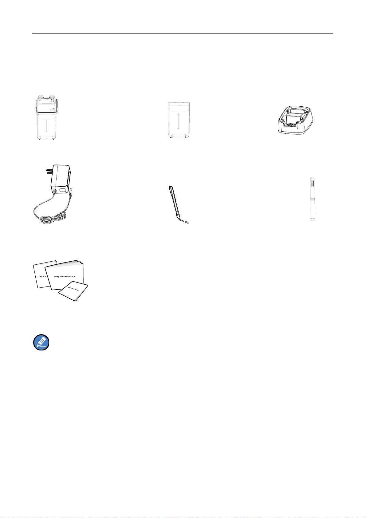
Checking Items in the Package
Please unp ack carefully and check that all items list ed below are receive d. If any ite m is missing or
damaged, please contact your dealer.
Radio Unit Battery Charger
Power Adapter S trap Antenna
Manuals
Note: The antenna may vary with different frequency bands. And the frequency band is marked on
the label of antenna; if not, please refer to the label on the terminal for frequency band information.
9
Page 11
Product Overview
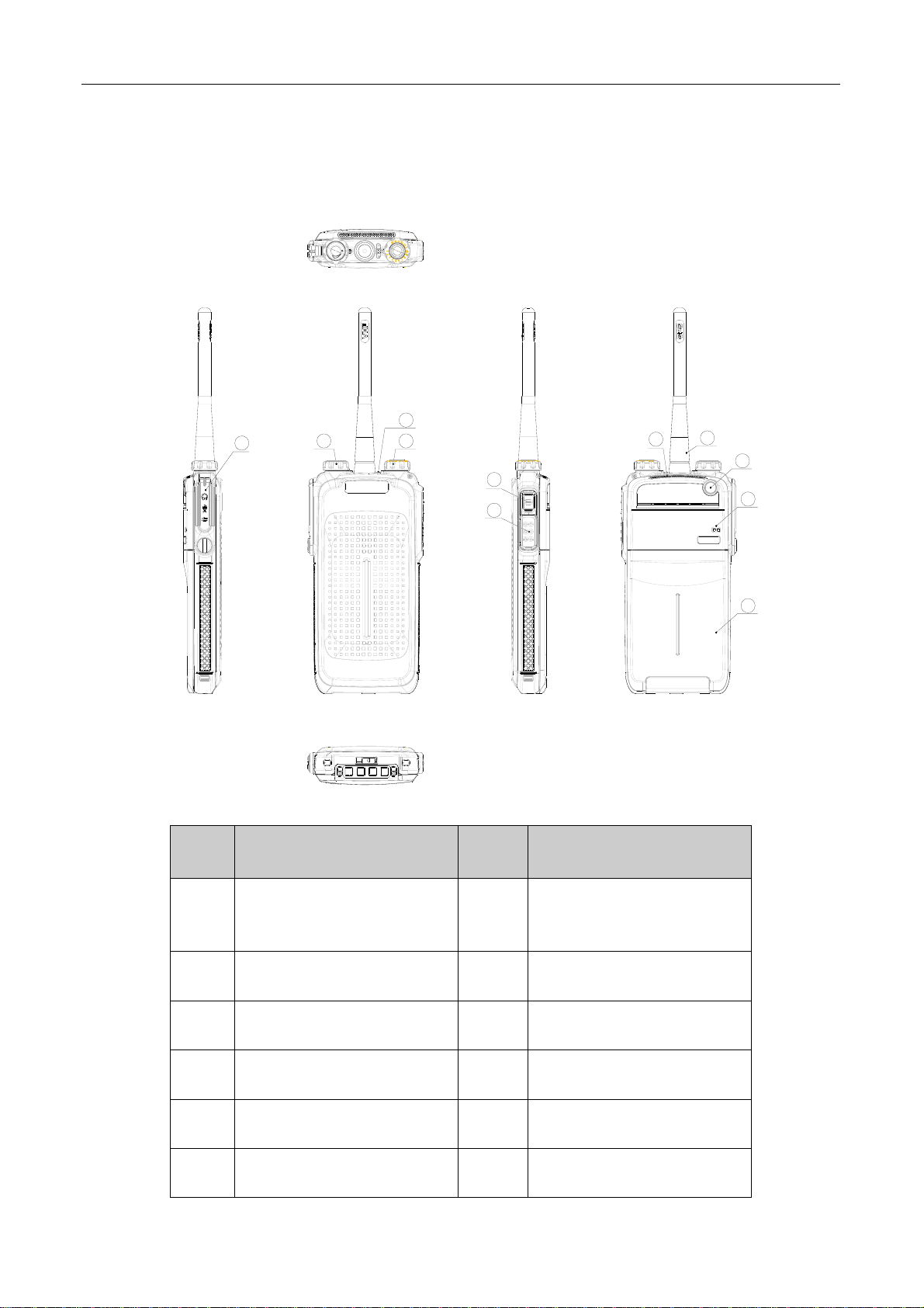
Product Controls
3
1
42
5
6
7
8
9
10
No. Part Name No. Part Name
Radio On-Of f/Volume
1
○
3
○
5
○
Accessory Jack
LED Indicator
SK (Side Key)
2
○
4
○
6
○
Control Knob
Channel Selector Knob
PTT Key
11
7
○
9
○
11
○
10
Speaker
TK (Top Key)
Battery
8
○
10
○
Antenna
Microphone
Page 12
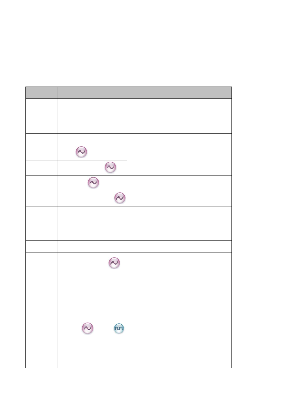
Programmable Keys
For enhanced convenience, you may request your dealer to program the keys SK and TK as shortcuts to
the functions listed below:
No. Shortcut Key Function
1
2
3
4
5
6
7
8
9
10
Zone Up
To select a desired zone quickly
Zone Down
Adjust Power Level To adjust power level quickly
Talk Around To directly communicate with other radios
Monitor
Monitor Momentary
Squelch Off
Squelch Off Momentary
Scan To receive signals on other channels
Nuisance Temporary Delete
To adjust the condition for incoming signal
match
To always u nmute speaker no matter whether
carrier is present or not
To tempora rily ignor e unwa nted channel
activity
11
12
13
14
15
16
17
11
Emergency To summon help in emergent situations
To temporar ily ad just the squelch threshol d
Adjust Squelch Level
Battery Strength Indicator To indicate the battery strength
Man Down To activate Emergency in the case that the
Scrambler
Lone Worker To protect the operators from accidents
One Touch Call 1-5 To make corresponding services
/Encrypt
required for the radio to unmute
radio is positioned aslant for a pre set time
period due to an unexpected situation
To encrypt your voice so as to guara ntee
privacy of your communication
Page 13

18
19
Tel em et ry
Roam
To supervise remote devices
To communicate betwe en sites in the IP
Multi-site Connect system.
Note:
(1) Long and short press of a key can be assigned with different functions by your dealer.
(2) The TK is programmed as the Emergency key by default, and is programmable by your dealer.
12
Page 14
Before Use
Charging the Battery
Power off the radio before charging it.
Use only the charger and battery specified by Hytera. Charger LED can indicate the charging process.
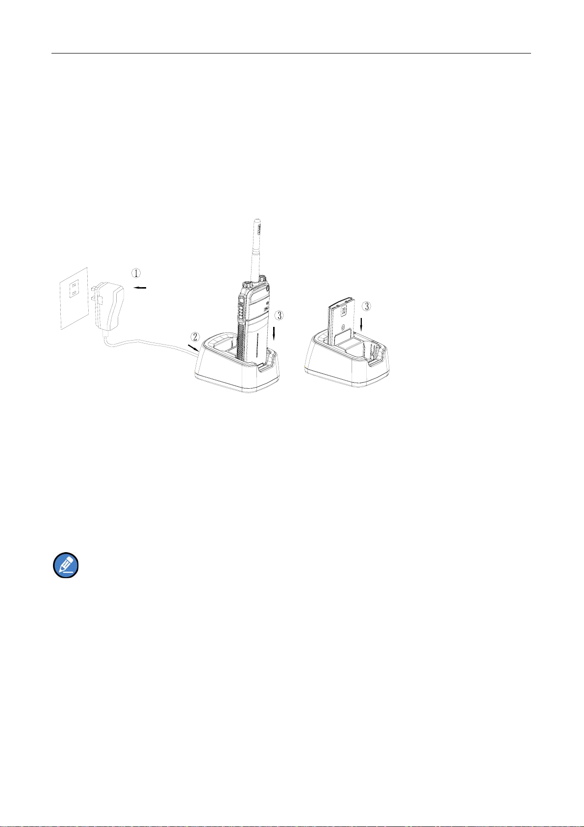
Charging Diagram
Procedures
1. Connect the power adapter to AC socket. See arrow ①.
2. Plug the power adapter into the rear jack of the charger. See arrow ②.
3. Place the radio with the battery attached, or the battery alone, into the charger.
4. The charging process initiates when LED glows red, and is completed when LED glows green.
Note: To achieve optimal battery performance, please charge the battery fo r 3 hours bef ore initial
use.
13
Page 15
LED Indicator
LED Indicator Charger Status
Red LED flashes slowly. Standby (no load)
Red LED glows. Charging
Orange LED glows. 90% charged
Green LED glows. Fully charged
Red LED flashes rapidly. Failure
Caution: Be sure to read the Safety Information Booklet, to get necessary safety information.
Assembling Accessories
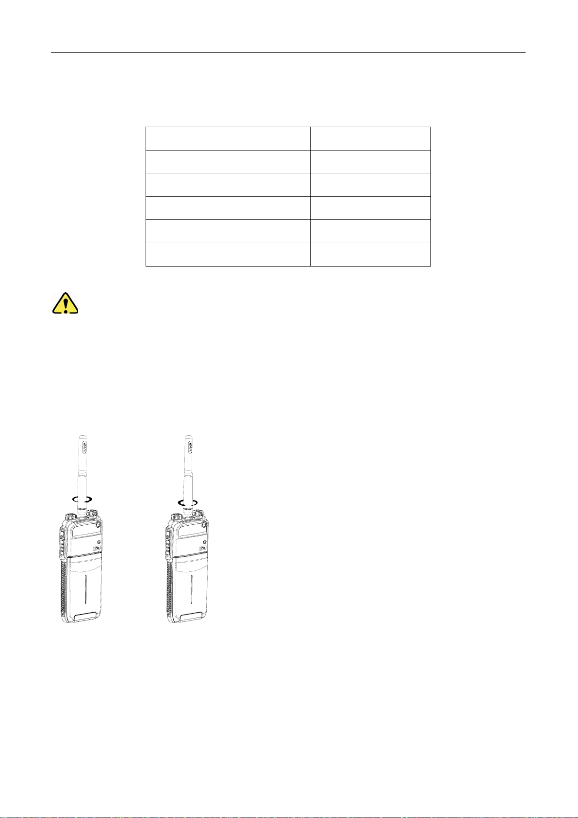
Assembling the Antenna
Turn the antenna clockwise to fasten it.
To remove the antenna, rotate it counter-clockwise.
Assembling the Battery
1. Insert the battery into top of the radio. See arrow ○1.
2. Slightly press the bottom of the battery until a click is heard. See arrow
14
2.
○
Page 16
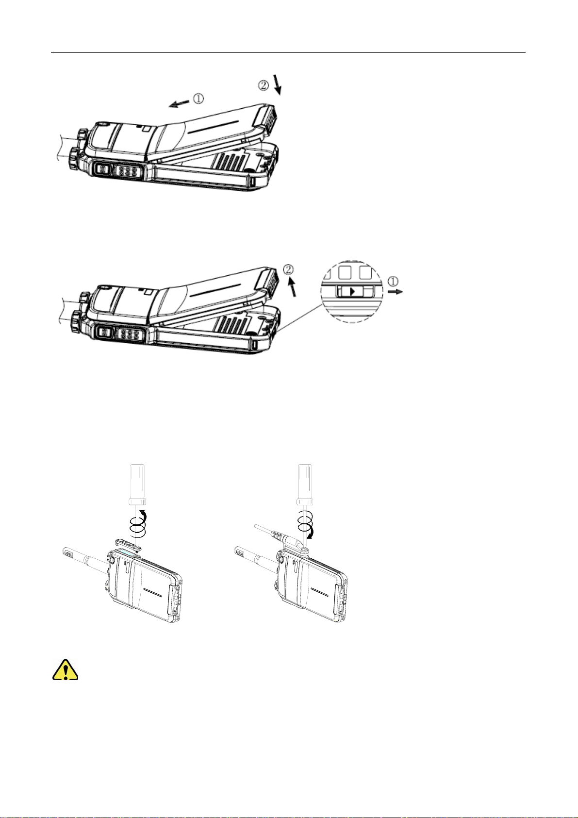
To remove the battery, turn off the radi o first. Then push the lock to loosen th e battery latch (a s indicated by
1 ) , and slide the battery latch upwards to unlock the battery.
○
Assembling the Audio Accessory
1. Open the accessory jack cover as the arrow shown.
2. Align the plug with the accessory jack.
3. Tighten the screw on the plug.
To remove accessories, loosen the screw.
Caution: Please att ach the accessory prop erly; o therwise, waterproof pe rformance of the radi o
may get affected.
15
Page 17
Status Indication
LED Indicator
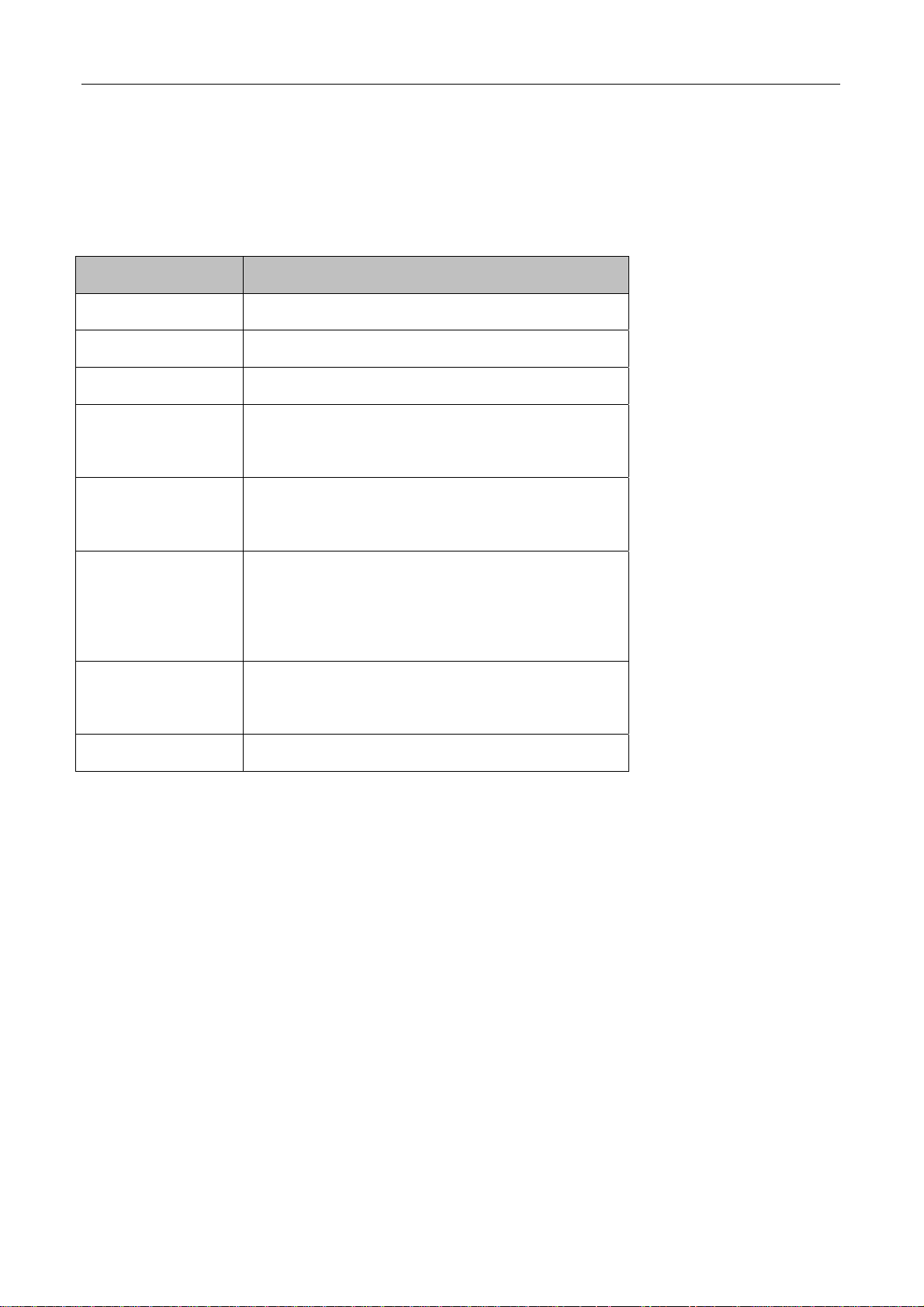
The top LED indicator will help you easily identify the current radio status.
LED Indication Radio Status
LED flashes green. Powering on
LED glows red. Transmitting
LED glows green. Receiving
LED flashes oran ge
Scanning
slowly.
LED flashes oran ge
Emergency
rapidly.
After voice communication en ds, you can hol d
LED glows orange.
LED flashes red a nd
blue.
LED flashes blue. Paired successfully
16
down the PTT key to t alk while the L ED is glowing
orange.
Paring the Bluetooth
Page 18

Basic Operations
Turning the Radio On/Off
Rotate the Radio On-Off/Volume Control knob clockwise/counter-clockwise until a click is heard to turn
the radio on/off.
Adjusting the Volume
After turning the radio on, rotate the Radio On-Off/Volume Control knob clockwise to increase the call
volume, or counter-clockwise to decrease it.
Selecting a Zone
A zone is a group of channels exhibiting the same property, and is programmed by your dealer. The radio
supports 3 zones: Zone 1, Zone 2 and Zone 3. Each zone contains 16 channels at most.
You may quickly toggle to your desired zone by pressing the progr ammed Zone Up or Zone Down key.
In the process, you will hear one alert tone for Zone 1, two alert tones for Zone 2 and three alert tones for
Zone 3.
Selecting a Channel
After turning the radio on, rotate the Channel Selector knob to select a desired channel.
Switching the Channel Mode
Each chann el can be programmed as either an alog chan nel or digit al chann el. If th e current zo ne
includes both analog and digital channels, you may quickly switch between digital and analog through the
Channel Selector knob.
17
Page 19

Enabling/Disabling the Bluetooth
Short press the SK key twice to enable/disable the Bluetooth. If it is enabled, the LED will flash blue.
Caution: Please use our POA43 Bluetooth earpiece.
To use the Bluetooth function properly, please arrange the radio by any of the following way:
z Wear the radio and the Bluetooth earpiece on the same side of your body, with the radio’s front side
facing your body. The distance between the radio and Bluetooth earpiece must not exceed 0.5m.
z lPlace the radio at a place no more than 2m away from the Bluetooth earpiece, with the radio’s rear
side facing the Bluetooth earpiece.
Pairing Bluetooth Device with the Radio
Fisrt with your radio’s Bluetooth feature ON:
1,Turn on the accessory, then place it close to the radio using the Bl ue dot-pairing indicator on the radi o
and theaccessory.
2,If the pairing process is successful, the radio sounds an incremental-pitched tone to indicate paired.
3,If the p airing process fails, t he radio sounds a short, lowpitched t one. The display shows P AIRFAIL.
Repeat step 1 again.
18
Page 20

Call
Note:
Your dealer may preset a cont act for each digit al channel. Th e preset contact could be a Private Call
contact, a Group Call contact or an All Call contact.
To ensure optimal volume of the receiving ra dio, hold the p alm micropho ne appr oximately 2.5 to 5
centimeters away from your mouth.
Private Call
Transmitting a Private Call
In the standby mode, hold down the PTT key to transmit a Private Call to the Private Call contact preset
for the current channel.
Receiving and Responding to a Private Call
When a Private Call is re ceived, you can listen to it without any operation, and you ma y hold down th e
PTT key within the preset time period to call back.
Group Call
Transmitting a Group Call
In standby mode, hold down the PTT key to transmit a Group Call to the Group Call contact preset for the
current channel.
Receiving and Responding to a Group Call
When a Gro up Call is received, you can listen to it without a ny operation, and you may hold dow n the
PTT key within the preset time period to call back.
All Call
Transmitting an All Call
In st andby mode, hold down th e PTT key to transmit an All Call to t he All Call cont act preset for the
current channel.
19
Page 21

Note: You can transmit an All Call only when it is enabled by your dealer.
Receiving an All Call
When an All Call is received, you can listen to it without any operation.
Note: You cannot respond to an All Call.
Calls on Analog Channels
To transmit on an analo g channel, hold down the PTT key an d speak into the microphone. T o receive,
release the PTT key.
20
Page 22

Functions and Operations
Adjust Power Level
With this feature, you may switch power levels quickly. Generally, we recommend you to adopt low power
for battery s aving. H owever, if yo u cannot communicate with radios located at a dist ant place with low
power, please select high power.
Operation:
Press the programmed Adjust Power Level key to switch between high po wer and low power (from low
power to hig h power: a high-pitched tone sounds; from high power to lo w power: a l ow-pitched tone
sounds).
Scan
The Scan feature allows you to listen to communication activities on other channels so that you can keep
a close track of your team members.
Operation:
1. To enable the feature, press the programmed Scan key in st andby m ode (a hi gh-pitched tone
sounds); or
Switch to a channel for which the feature “Auto Scan” is enabled via the programming software.
2. After the feature is enabled, your radi o will scan according to the scan list set for the channel on
which scanning starts. The scanning process is as follows:
z During scanning, the LED flashes orange.
z When activities are detected on a channel, the radio will stay on the channel to receive current
activities, and the LED glows green.
z If you don’t want to hear activities on the channel, press the programmed Nuisance Temporary
Delete key to remove the channel from the scan list temporarily.
z If you want to continue staying on the channel, press the programmed Monitor or Squelch Off
key during scan stay.
3. To exit the scanning process, press the programmed Scan key again (a low-pitched tone sounds).
21
Page 23

Talk Around
This feature allows you to cont inue communication even w hen the repeat er malfunctions, or when yo ur
radio is out of the repeater’s range but within the coverage range of other radios.
Operation:
Press the programmed Talk Around key to enable the feature (a high-pitched tone so unds). To disable
the feature, press this key again (a low-pitched tone sounds).
Monitor
To adjust match conditions for signal receiving, you can enable the feature “Monitor”.
Operation:
Press the programmed Monitor key to enable the feature (a hi gh-pitched tone sounds). To disable
the feature, press this key again (a low-pitched tone sounds).
Hold do wn the pro grammed Monitor Momentary key to en able the feat ure (a hi gh-pitched tone
sounds). To disable the feature, release this key (a low-pitched tone sounds).
Squelch Off
If the feature “Squelch Off” is enabled, your radio’s speaker will keep unmuted no matter whether carrier
is present.
Operation:
Press the programmed Squelch Off key to enabl e the feature , and the ra dio sounds background
noise (a high -pitched tone sounds). To disable the feature, press this key again (a low -pitched tone
sounds).
Hold dow n the prog rammed Squelch Off Momentary key to enable th e feature, and the radio
sounds backgrou nd nois e (a hig h-pitched tone sounds). T o d isable the feature, re lease this key (a
low-pitched tone sounds).
22
Page 24

Adjust Squelch Level
This feature allows you to adjust the squelch threshold required for the radio to unmute.
Generally, “Tight” is used in high noise envir onment. It requires stronger signal for the radio to unmute.
If the squelch level is set to Open, the speaker will keep unmuted irrespective of the satisfaction of
decoding conditions.
Operation:
Press the programmed Adjust Squelch Level key to switch among Tight, Open and Normal (from Tight
to Open, a low-pitched tone and background sound are heard; from Open to Normal, a high-pitched tone
is heard and the background sound disappears; from Normal to Tight, a high-pitched tone is heard).
One Touch Call
You can request your dealer to set the One Touch Call key. By pressing such programmed key, you can
make corresponding services detailed as below:
z Services on the analog channel: to make a call to the 5-Tone or 2-Tone contact.
z Services on the digital channel:
To send message to the Group Call contact.
To send message or make control services to the Private Call contact.
The control services con tain: Alert Call, Radio Check, Remote Monitor, Radio Enable or Radi o
Disable.
Alert Call
You can send an alert call to a Private Call cont act. The called party will see the alert and can
call you back.
Radio Check
You can send a Radio C heck command to a Private Ca ll contact, so a s to confirm whether it is
powered on or running on the current channel without disturbing it.
Remote Monitor
You can en able the microphon e of a Private Ca ll cont act, and monitor it s a ctivities or
background voices remotely.
Radio Enable
23
Page 25

You can enable the radio of a Private Call contact remotely and allow it to be used normally.
Radio Disable
You can disable the radio of a Private Call contact remotely and disallow it to be used normally.
Telemetry
This feature allows you to remotely supervise the device connected with a radio. With this feature,
you can control the device and view its status in the case that you are away from the device.
The method for supervising the device is programmable by your dealer. The available methods are:
z To supervise the device via the radio
If a device is connected with a radio, you can use another radio to supervise the device. All the
radios involved should be configured with the Telemetry feature. For example, the dealer
enables the Telemetry feature for both Radio A and Radio B, and assign the Telemetry feature to
the SK key on Radio A. To supervise the device C, connect it with Radio B, and press the SK key
on Radio A.
z To supervise the device via a third-party software
If the Telemetry feature is enabled for the radio by your dealer, you can supervise the device
connected with the radio via a third-party software.
Roam
This feature allows the radio to communicate betwee n sites in the IP Multi-site Connect syste m. If
enabled, the radio can communicate via any site in the IP Multi-site Connec t system, thus ensurin g
seamless communication in the system.
Operation:
Press the programmed Roam key to enable or disable the feature.
Emergency
In case of an emerge ncy, you can use the feature to ask for help from your companion or control center.
The Emerge ncy process has the high est priority. You can ma ke emergency operation even when your
radio is transmitting or receiving.
To enable th e feature on a channel, an emer gency system must be assigned to the channel via the
programming software. In addition, the Emergen cy type, Emerge ncy ID type an d Emergency mode are
settable via the programming software.
24
Page 26
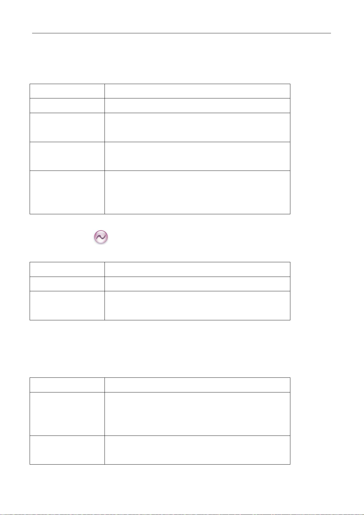
Emergency Type
For each Emergency m ode, there a re four Emergency types available. You can select one of them via
your dealer:
Emergency Type Description
Siren Only In Emergency mode, the radio will sound shrill alarm tone.
Regular In Emergency mode, the radio will give audible and visible
indication.
Silent In Emergency mode, the radio won't give any audible or visible
indication.
Silent with Voice In Emergency mode, the radio won’t give any audible or visible
indication, but will receive voice ACK from the co mpanion or
control center automatically.
Emergency ID Type
Your radio supports two Emergency ID types. You can select one of them via your dealer:
Emergency ID Type Description
None No signaling is used when the radio sends alarm information.
HDC1200 HDC1200 signaling is used when the radio sends alarm
information.
Emergency Mode
Your radio supports three Emergency modes. You can select one of them via your dealer (Note: For the
following operation methods, we take the “Regular” type as an example).
Emergency Mode Description
Alarm In this mode, you can send alarm information to your
companion or control center by pr essing the programmed
Emergency key, but you cannot talk with them.
Alarm with Call In this mode, you can se nd alarm inf ormation by pressing the
programmed Emergency key . When the alarm to ne
25
Page 27

disappears (None) or af ter the Emergency ID is sent
(HDC1200), you can spe ak into the microphone, allowing your
voice and b ackground n oise to be transmitted automatically
(you do not need to hold down the PTT key).
Call Only
In this mode, press the programmed Emergency key to go to
the Revert C hannel, and speak into the micropho ne, allowing
your voice and bac kground noise to be transmitte d
automatically (you do not need to hold down the PTT key).
Operation Methods for Analog Emergency
Alarm (None & HDC1200)
Operation: Press the programmed Emergency key to send alarm informat ion, and the LED glows r ed.
(None: If “Local Emergency Alarm" is enabled via the programming software, an alarm tone will sound.)
The following methods are available for you to exit the Emergency mode:
1. Once the Alarm Cycles expire, the radio will exit the Emergency mode automatically.
2. Long press the programmed Emergency key.
3. Hold do wn the PTT key. The radio will transmit o n the c hannel on which the r adio operates before
entering the Emergency mode. (HDC1200)
Alarm with Call (None & HDC1200)
Operation:
1. Press the programmed Emergency key to send alarm information, and the LED glows red. (None: If
“Local Emergency Alarm" is enabled via the programming software, an alarm tone will sound.)
2. When the al arm tone disappe ars (No ne) or af ter the Emerge ncy ID is se nt (HDC1 200), you can
speak into the microphone to make an emergency call.
3. When the LED flashes orange, your radio is receiving.
Two methods are available for you to exit the Emergency mode:
1. After the preset Alarm Cycles and V oice Cycles expire, the r adio will exit the Emer gency mode
automatically. (None)
2. Long press the programmed Emergency key.
26
Page 28

Call Only (HDC1200)
Operation:
1. Press the programmed Emergency key to go to the Revert Channel, and the LED glows red.
2. If the feature “Alarm with Call to Follow” is enabled, you can speak into the microphone to make an
emergency call when the LED glows red.
3. When the LED flashes orange, your radio is receiving.
To exit the Emergency mode, long press the programmed Emergency key.
Note: Your dealer may set the number of alarm cycles and alarm duration (None), number of polite
retries and impolite retries (HDC12 00), number of vo ice cycles, duration of each transmission and TX
interval.
Operation Method for Digital Emergency
Alarm
Operation: Press the programmed Emergency key to send alarm inform ation. At this time, the L ED
glows red.
Two methods are available for you to exit the Emergency mode:
1. Once the Alarm Cycles expire, the radio will exit the Emergency mode automatically.
2. Long press the programmed Emergency key.
Alarm with Call
Operation:
1. Press the programmed Emergency key to send alarm information. At this time, the LED glows red.
2. When the LED solidly glows red, you can speak into the microphone to make an emergency call.
3. When the LED flashes orange quickly, you can receive. And when a ca ll is received, the LED glows
green solidly.
4. If the preset Voice Cycles expire, you can press the PTT key to make the emergency ca ll again (the
LED glows red). Release the PTT key to receive (the LED flashes orange quickly); when a call is
received, the LED glows green solidly.
To exit the Emergency mode, long press the programmed Emergency key.
27
Page 29

Call Only
Operation:
1. Press the programmed Emergency key to go to the Revert Channel.
2. If the feature “Alarm with Call to Follow” is enabled, you can speak into the microphone to make an
emergency call when the LED glows red.
3. When the LED flashes orange, your radio is receiving.
If the preset Voice Cycles expire, you can hold down the PTT key to make the emergency call again (the
LED glows red). After the emergency call is transmitted, please release the PTT key to receive.
To exit the Emergency mode, long press the programmed Emergency key.
Note: Your dealer may set the number of polite retries and impolite retries, number of voice cycles,
duration of each transmission and TX interval.
Man Down
With this feature, your radio will alarm automatic ally to summon help from your comp anion if it i s
positioned aslant for a certain time period.
Operation:
1. To enable the feature,
z Press the programmed Man Down key (a high-pitched tone sounds); or
z Turn on the radio if the feature is enabled via the programming software.
2. Your radio will sound a pre-alert tone if it is positio ned aslant for a preset time period, and will ent er
the Emergency mode if y ou do not place it vertically within such time period. To exit the Emergency
mode, please place it upright.
3. To disable the feature,
z Press the programmed Man Down key (a low-pitched tone sounds).
Scrambler /Encrypt
The Scrambler/Encrypt feature can encrypt your audio signals to prevent eavesdropping. Thus privacy of
your communication is guaranteed.
Operation:
z Press the programmed Scrambler/Encrypt key to enable Scrambler or Encrypt on the curren t
channel (a high-pitched tone sounds); press the key again to disable the feature (a low-pitched tone
28
Page 30
sounds).
z If the Scrambler/Encrypt feature is enabled for a channel via the programming software, switch to the
channel to enable the feature, or exit the channel to disable the feature.
Lone Worker
This feature is ideal for p ersons who work lonely. If you encounter an incident and cannot operate your
radio within the preset ti me per iod, your radio will alarm a utomatically to summon help from your
companion.
Operation:
1. To enable the feature,
Press the programmed Lone Worker key (a high-pitched tone sounds); or
Turn on the radio if the feature is enabled via the programming software.
2. If you cannot operate your radio within a preset response period, your radio will give alerts before this
period expires (dependent on the settings by your dealer). At this time, you can terminate such alerts
by rot ating a knob or pressing a key . When the response period expi res, your radi o will trigger the
current emergency system automatically.
3. To disable the feature,
Press the programmed Lone Worker key (a low-pitched tone sounds).
Note: If the Lone W orker feature is not disabled before your radio is powered of f, it will remain
enabled when powered on again.
Battery Strength Indicator
This feature allows you to know the current battery strength.
Operation:
Hold down the programmed Battery Strength Indicator key, and the radio will give a specific indication
to represent the current battery strength. Release the key to exit.
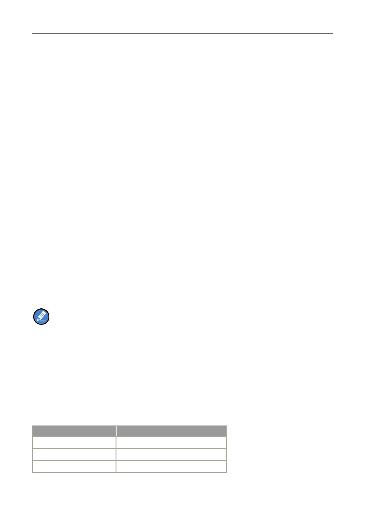
Indication Battery Strength
Green LED glows. High
Orange LED glows. Medium
Red LED glows. Low
29
Page 31

Red LED glows and the low
battery alert sounds.
Insufficient
Busy Channel Lockout
If enabled via the pro gramming sof tware, this feature can prevent yo ur radio interf ering with other
transmitting terminals on the same channel. If you hold d own t he PTT key while the channel is in u se,
your radio will keep beeping, alerting you to transmission prohibition. To stop beeping, please release the
PTT key. When the channel is free, you can press and hold down the PTT key to transmit.
Time-out Timer (TOT)
The purpose of TOT is to prevent any user from occupying a channel for an extended period. If the preset
time expires, the product will automatically te rminate transmission and keep beeping. To stop beeping,
please relea se the PTT key. You must wait for a certain time period ( preset by your d ealer) to initiate
another transmission.
If the pre-alert function is set by your dealer, your radio will alert you to the TOT expiration in advance.
Note: This feature is null in Emergency mode.
Pseudo Trunking
If enabled vi a the progra mming software, If your radi o operates on a channel with this feature enabled
and one time slot is already occupied, it can transmit and receive on the other free time slot, allowing you
to communicate timely under emergent situations.
MIC AGC
If enabled via the programming software, your product will process the audio signals during transmission,
providing improved audio for the receiving product.
Radio Registration Service
If enabled vi a the programming sof tware, your radio will automatically register in the system within a
certain period after power-on. Then it can acquire online information of other radios via accessing specific
30
Page 32

servers within the valid registration period.
GPS Revert
If enabled vi a the programming software, your registered radio will transfe r its positioning information to
the system when the system requires such information.
31
Page 33
Troubleshooting
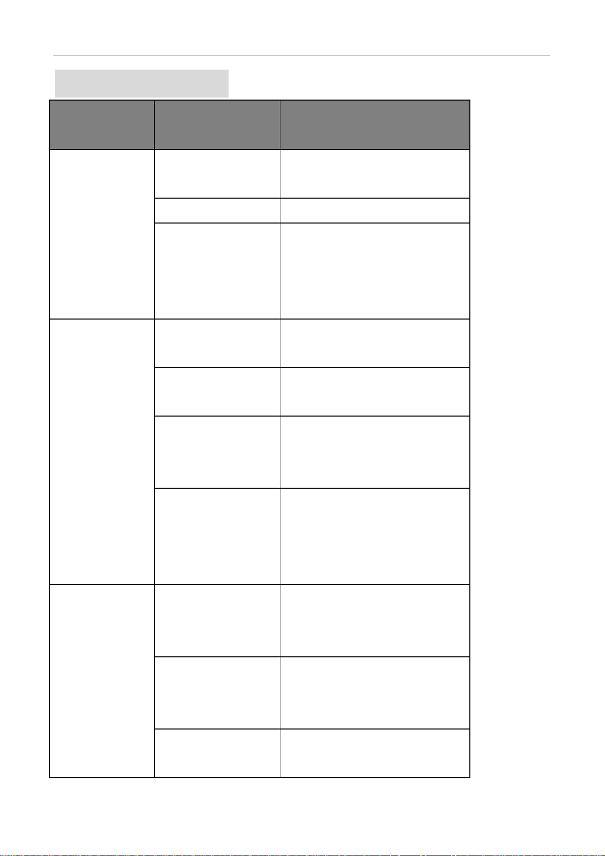
Phenomena Analysis Solution
The battery may be
Remove the battery and attach it again.
improperly installed.
The battery may run out. Recharge or replace the battery.
The product can not be
The battery may suffer from
powered on.
poor contact caused by
Clean the battery contacts. If the problem
can not be solved, contact your dealer or
During receiving
signals, the voice is
weak, discontinuous or
totally inactive.
dirtied or damaged battery
contacts.
The battery strength may be
too low.
The volume may be set to a
low level.
The antenna may get loose
or may be improperly
installed.
The speaker may be
blocked or damaged.
authorized service center for inspection and
repair.
Recharge or replace the battery.
Increase the volume.
Power off the product, and re-install the
antenna.
Clean surface of the speaker. If the problem
can not be solved, contact your dealer or
authorized service center for inspection and
repair.
The frequency or signaling
Set your TX/RX frequency and signaling to
may be inconsistent with
the same as that of other members.
that of other members.
You can not
The channel type
communicate with
(digital/analog) may be set
other members.
inconsistently.
You may be too far away
from the group members.
32
Make sure all members are on the same
digital/analog channel.
Move towards other members.
Page 34

You may be interrupted by
Irrelevant
communication or
noise is heard on the
channel.
The noise is too loud.
products using the same
frequency.
The product may be set with
no signaling.
You may be too far away
from other members.
You may be at an
unfavorable position. For
example, your
communication may be
blocked by high buildings or
Change the frequency, or adjust the squelch
level.
Set signaling for all member products to
avoid interference at the same frequency.
Move towards other members.
Move to an open and flat area, and restart
the product.
frustrated in the
underground areas.
You may suffer from
The GPS cannot locate
your position.
The Bluetooth cannot
be paired.
external disturbance (such
as electromagnetic
interference).
No GPS signal is received.
The battery power for the
Bluetooth may run low.
The Bluetooth may be too
far away from the product.
Stay away from equipment that may cause
interference.
Move to an open and flat area, and restart
the product.
Charge the Bluetooth.
Move the Bluetooth towards the product.
If the above solutions can not fix your problems, or you may have some other queries, please contact us
or your local dealer for more technical support.
33
Page 35

Care and Cleaning
To guara ntee optimal pe rformance a s well as a long service life of the produc t, please follow the tips
below.
Product Care
Do not pierce or scrape the product with any edged instruments or hard objects.
Keep the product far away from substances that can corrode the circuit.
Do not hold the product by its antenna or earpiece cable directly.
Attach the accessory jack cover when the product is not in use.
Product Cleaning
Clean up the dust and fine p articles on the product surface and charging piece with a clean and dr y
lint-free cloth or a brush regularly.
Use neutral cleanser and a non-wo ven fabric to clean the keys, control knobs and front case af ter
long-time use. Do not use chemic al prep arations such as st ain removers, alcohol, sprays or oil
preparations, so as to avoid su rface case damage. Make sure the prod uct is completely dry before
use.
Caution: Power off and remove the battery before cleaning.
34
 Loading...