

Page 1

8110070001700
Page 2

Thank you for purchasing Hytera TC-700P portable radio. This
easy-to-use radio will deliver you secure, instant and reliable
communication ser vice at peak efciency.
To derive optimum performance from your radio, please read
th is m anua l an d th e suppl ied S afe t y In form atio n Boo klet
carefully before use.
Page 3
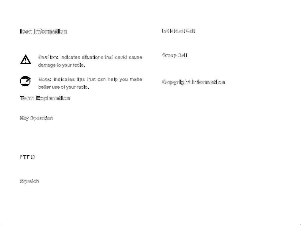
Icon Information
The following icons are available through this manual:
Caution: indicates situations that could cause
damage to your radio.
No t e: i ndi c a tes tip s th at c a n help y ou make
better use of your radio.
Term Explanation
The following terms will appear through this manual:
Key Operation
Short press: to press a key and release it quickly.
Long press: to press the key and remain holding it down
for a predened period.
Hold down: to press a key and remain holding it down.
PTT ID
PTT ID, namely radio identity, allows a radio with display
and the control center to identify the calling party.
Squelch
Th i s te c hnolo g y can rem o ve exces s i ve b a ckg r o und
noises, improving your communication quality.
Individual Call
Individual call is a call initiated by a single user to another
user, involving the calling party and the called party only.
Group Call
Group call is a call initiated by a single user to a group,
involving the calling par ty and all the group members.
Copyright Information
Hytera and HYT are trademarks or registered trademarks
of Hytera in the PRC and other countries and/or areas.
Hy te ra re t ains the owne r s hip o f it s trad e marks a nd
pr odu ct n ames . All othe r tr ade mar ks and/ or p roduct
names that may be used in this manual are properties of
their respective owners.
The Hytera product described in this manual may include
Hytera c omputer progr ams stored in memor y or other
media. Laws in the PRC and/or other countries or areas
preserve for Hytera exclusive rights for Hytera computer
progr ams. The p urc has e of this pro duc t shal l not b e
deemed to grant, either directly or by implicat ion, any
rights to the purchaser with respect to Hytera computer
programs. Any Hy tera computer programs may not be
copied, modified, dist ributed, dec ompiled, or reverse-
en g i neered i n an y ma n n er w i t h o u t th e pri o r written
consent of Hy tera.
Page 4

Disclaimer
RF Energy Exposure Compliance
H y t e r a e nd ea v or s to ac h i e ve th e ac c u r a c y a n d
c o m p let e n e ss of th i s man u a l , but no wa r ran t y of
ac curac y or reli abi lit y is give n. All the spec ific ati ons
and designs are subject to change without prior notice
due to co nti nuo us techn olo g y develop ment. No pa r t
of this manual may be copied, modified, translated, or
distr ibuted in any manner without t he express written
permission of Hytera.
If you have any suggestions or would like to learn more
details, please visit us at: http://www.hytera.cn.
You r ra d i o is d e signe d and t e s ted t o comp l y wit h a
nu mber of n atio n al and in tern atio n al stand a rds a n d
guide lin es ( lis ted belo w) r ega rdi ng h uman expos ure
to radio frequency ele ctromagnetic energy. Thi s radio
complies with the IEEE and ICNIRP exposure limits for
occu pat ional/co ntr olled RF e xpo sur e envi ronme nt a t
operating duty factors of up to 50% transmitting and is
authorized by the FCC for occupational use only. In terms
of measuring RF energy for compliance with the FCC
exposure guidelines, your radio radiates measurable RF
energy only while it is transmitting (during talking), not
when it is receiving (listening) or in standby mode.
Your r adi o co mpl i es w ith the follow ing of RF ener g y
exposure standards and guidelines
United States Federal Communications Commission,
●
Code of Federal Regulations; 47CFR part 2 sub-par t
J
American N a t i o n a l Standar d s Institut e (ANSI) /
●
Institute of Electrical and Electronic Engineers (IEEE)
C95. 1-1992
Institute of Electrical and Electronic Engineers (IEEE)
●
C95. 1-1999 Edition
International Commission on Non-Ionizing Radiation
●
Protection (ICNIRP) 1998
Page 5

Operational Instructions and Training Guidelines
To ensure optimal performance and compliance with the
occupational/controlled environment RF energy exposure
limits in the above standards and guidelines, users should
transmit no more than 50% of the time and always adhere
to the following procedures:
Transmit and Receive
To transmit (talk), push the Push-To-Talk (PTT) key; to
receive, release the PTT key.
FCC Licensing Information
Part 15 Compliance
This equipment has been tested and found to comply with
the limits for a Class B digital device, pursuant to part 15
of the FCC Rules. These limits are designed to provide
reasonable protection against harmful interference in a
residential installation. This equipment generates, uses
and can radiate radio frequency energy and, if not installed
and used in accordance with the instructions, may cause
harmful interference to radio communications. However,
there is no guarantee that interference will not occur in
a particular installation. If this equipment does cause
harmful interference to radio or television reception, which
can be determined by turning the equipment off and on,
the user is encouraged to try to correct the interference by
one or more of the following measures:
Reorient or relocate the receiving antenna.
●
Increase the separation between the equipment and
●
receiver.
C o nn e c t t h e eq u ip me nt in to an ou t le t o n a
●
circuit dif ferent f rom that to which the rece iver is
connected.
Cons u l t th e deal e r or a n ex p e r i e n c e d ra d i o / T V
●
technician for help.
FCC Licensing Requirements
A license from Federal Communications Commission is
required prior to use. Your dealer will program each radio
with your authorized frequencies, signaling codes, etc.,
and will be there to meet your communications needs
as your system expands. Contact your dealer for more
information.
Page 6

Contents
Checking Items in the Package -------------------------------3
Radio Overview --------------------------------------------------- 4
Radio Controls ---------------------------------------------- 4
Programmable Keys --------------------------------------- 5
Before Use---------------------------------------------------------- 7
Charging the Battery --------------------------------------- 7
Assembly and Disassembly ------------------------------ 8
Status Indications ------------------------------------------------- 10
Basic Operations -------------------------------------------------- 11
Turning the Radio On/Off --------------------------------- 11
Adjusting the Volume -------------------------------------- 11
Selecting a Channel ---------------------------------------- 11
Transmitting/Receiving a Call ---------------------------- 11
Functions and Operations -------------------------------------- 12
Adjust Power Level ----------------------------------------- 12
Monitor--------------------------------------------------------- 12
Squelch Off --------------------------------------------------- 12
Cancel Call --------------------------------------------------- 12
Scan ------------------------------------------------------------ 13
Emergency --------------------------------------------------- 14
VOX ------------------------------------------------------------ 15
Talk Around --------------------------------------------------- 15
Adjust Squelch Level -------------------------------------- 16
Scrambler ----------------------------------------------------- 16
Compandor --------------------------------------------------- 16
Call Forward-------------------------------------------------- 16
Whisper-------------------------------------------------------- 16
Lone Worker ------------------------------------------------- 17
Man Down (optional) --------------------------------------- 17
Auto Contact ------------------------------------------------- 17
Call 1-Call 5 -------------------------------------------------- 18
Battery Power Indicator ----------------------------------- 18
Rental Time Indicator -------------------------------------- 18
Channel Announce Enable ------------------------------- 18
Channel Announce Temporary Enable ---------------- 19
Patrol (optional) --------------------------------------------- 19
Vibrate (optional) -------------------------------------------- 20
Time-out Timer (TOT) -------------------------------------- 20
Safety Check ------------------------------------------------- 20
Low Battery Alert -------------------------------------------- 20
Signaling Introduction -------------------------------------------- 21
Phone ---------------------------------------------------------- 21
HDC2400™ Signaling ------------------------------------- 21
1
Page 7
Contents
5-Tone Signaling -------------------------------------------- 22
Troubleshooting --------------------------------------------------- 23
Care and Cleaning ----------------------------------------------- 25
Optional Accessories -------------------------------------------- 26
2
Page 8

Checking Items in the Package
Please unpack carefully and check that all items listed below are received. If any item is missing or damaged, please contact
your dealer.
Radio Unit Battery MCU Charger
Switching Power
Belt Clip Strap Antenna
Owner’s Manual & Safety Information Booklet
Note:
1.The above pictures are for reference only. Actual products may vary slightly.
2.The antenna may vary with different frequency bands. And the frequency band is marked on the label of antenna;
if not, please refer to the label on the radio for frequency band information.
3
Page 9
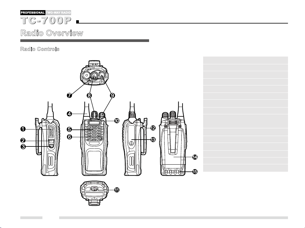
Radio Overview
Radio Controls
(1) PTT Key
(2) SK1 (Side Key 1)
(3) SK2 (Side Key 2)
(4) Antenna
(5) Speaker
(6) Microphone
(7) TK (Top Key)
(8) Channel Selector Knob
(9) Radi o On-Of f/ Volume Control
Knob
(10) LED Indicator
(11) Battery Latch
(12) Belt Clip
(13) Accessor y Jack
(14) Battery
(15) Charging Piece
4
Page 10

Radio Overview
Programmable Keys
For enhanced convenience, you may request your dealer to program the keys SK1, SK2, and TK as shortcuts to the functions
listed below:
No. Shortcut Keys Description
1 Adjust Power Level To adjust power level through one key press.
2 Monitor
3 Monitor Momentary
4 Squelch Off
5 Squelch Off Momentary
6 Cancel Call To quickly exit the established call.
7 Scan To listen to communication activities on other channels (Normal Scan)
8 Nuisance Temporar y Delete To select the closest base station to communicate (Vote Scan).
9 Nuisance Channel Delete To permanently ignore unwanted channel activity.
10 Emergency To summon help in emergent situations.
11 VOX To make the radio transmit automatically when you speak.
12 Talk Around To directly communicate with other radios.
13 Adjust Squelch Level To temp orarily adjust the s quelch t hreshol d req ui red for t he radi o to
14 Scrambler To en c r yp t yo u r vo i c e so as to gu a r a nt ee pr i v a c y of yo ur voi c e
15 Compandor To suppress ambient noise and improve audio quality.
16 Call Forward To forward a received call.
To adjust the condition for incoming signal match.
To always unmute speaker no matter whether carrier is present or not.
unmute.
communication.
5
Page 11

Radio Overview
No. Shortcut Keys Description
17 Whisper To make your voice heard clearly even if you speak with a very low voice.
18 Lone Worker To activate Emergency in case of unexpected circumstances.
19 Man Down To activate Emergency in case of unexpected circumstances.
20 Auto Contact To detect whether a member in the contact list is out of the communication
range.
21 Auto Contact Temporary Delete To temporarily remove the radio out of the communication range from the
contact list.
22 Call 1-Call 5 To quickly call other radios.
23 Battery Power Indicator To indicate the batter y strength.
24 Rental Time Indicator To indicate the remaining time that you are allowed to use a leased radio.
25 Channel Announce Enable To broadcast the channel number automatically upon power-on or channel
switching.
26 Channel Announce Temporary Enable To broadcast the number of the channel on which your radio is currently
operating.
27 Patrol Event Select To select an appropriate patrol event.
28 Patrol Event Afrm To send the selected patrol event.
6
Page 12

Before Use
Charging the Battery
Use only the charger and battery specied by Hytera. Charger
LED can indicate the charging process.
Charge Diagram
1
3
3
2
Procedures
1. Connect the power adapter to AC source. See① .
2. Plug the power adapter into the rear socket of the
charger. See ②.
3. Plac e the radio w ith the batte r y at tac hed , or the
battery alone, into the charger. See ③.
4. The charging process initiates when LED glows red,
and is completed when LED glows green.
Note: To achieve optimal battery performance, please
charge the battery for 5 hours before initial use.
Charge Indicator
LED Indicator Charge Status
Th e LE D fla shes red slo w ly ( 0 .2s
on/3s off).
The LED glows red. Charging
The LED glows green. Fully Charged
The L ED f las hes red rapi dly (0.2s
on/0.2s off).
Note: Be sure to read the Safety Information Booklet,
to get necessary safety information.
Standby (no load)
Error
7
Page 13

Before Use
Assembly and Disassembly
Attaching the Antenna
Turn the antenna clockwise to fasten it.
To remove the antenna, rotate it counter-clockwise.
8
Attaching the Battery
1. Make sure the battery is in parallel and good contact
wit h the aluminum chassis. The battery bot tom is
about 1 t o 2 centimeter s bel ow the b ot tom of the
radio’s body.
2. Align the batter y with the guide rails on the aluminum
chassis and slide it upwards until a “click” is heard.
To remove the battery, turn off the radio rst. Then slide
the battery latch downwards for 2-3 millimeters, and slide
the batter y down to remove it.
Page 14

Before Use
Attaching the Belt Clip
1. Remove the screws.
2. Align the screw holes on the belt clip with those on
the radio’s body, and then tighten the screws.
To remove the belt clip, loosen the screws.
Attaching Audio Accessory/Programming Cable
1. Remove the screw on the accessory jack cover by
rotating it counter-clockwise, and then remove the
accessory jack cover.
2. Insert the audio accessor y or programming cable.
3. A l ig n th e sc r ew on t h e au d io ac ce s so ry o r
programming c able with the threaded hole on the
radio, and then tighten the screw.
To rem ove th e audi o ac c ess or y/ pro g ram min g ca ble ,
loosen the screw.
Caution: When you are using an external accessory,
wa t e r p r o of performance of t h e ra d i o may get
affected.
9
Page 15
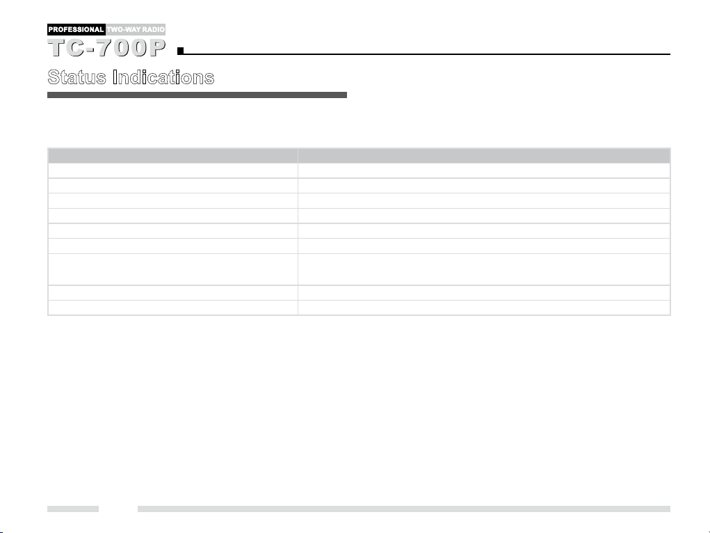
Status Indications
The top LED indicator will help you easily identify the current status of your radio.
Radio Status LED Indicator
Transmitting The LED glows red.
Receiving The LED glows green.
Call Transmission Alert The LED glows orange.
Call Alert (5-Tone) The LED ashes orange slowly.
Missed Call Alert (5-Tone) The LED ashes orange rapidly.
Call Alert (HDC2400TM) The LED ashes orange rapidly.
Selective Call Alert (HDC2400™) Group Call/Zone Call/Broadcast: the LED ashes orange once; Individual
Call: the LED ashes orange twice.
Scanning The LED ashes green.
Low battery The LED ashes red.
10
Page 16
Basic Operations
Turning the Radio On/Off
Rot a t e th e Ra di o On - O f f/ Vo lu m e Co n t ro l kn o b
clockwise/counter-clockwise until a click is heard to turn
the radio on/off.
Adjusting the Volume
Af t er t urn ing the ra dio on, rotate t he R a dio On- Of f/
Volume Control knob clockwise to increase the volume,
or counter-clockwise to decrease the volume.
Selecting a Channel
Rotate the Channel Selector knob to select a desired
channel.
Transmitting/Receiving a Call
To transmit a call, press and hold down t he PTT, and
speak into the microphone. During transmission, the LED
glows red.
To r e c ei v e , just r e l e a s e the PT T. W h e n a signal i s
received, the LED glows green.
Note:
1. To ensure optimal volume of the receiving radio,
hold the radio approximately 2.5 to 5 centimeters
away from your mouth.
2. Communication range may get affected in rainy
days or forest locations.
11
Page 17
Functions and Operations
Adjust Power Level
Generally, we recommend you to adopt low power for
power saving. However, if you cannot communicate with
other radios located at a distant place with low power,
please select medium power or high power.
Operation:
Pr e s s th e pro g r a m med A d j u s t Po w e r Le vel k ey t o
switch the power level (low power: the alert tone sounds
once; medium power: the alert tone sounds t wice; high
power: the alert tone sounds three times).
Monitor
To reduce match conditions for signal receiving, you can
enable the feature “Monitor”.
Operation:
Press the programmed Monitor key to enable the
●
feature (the aler t tone sounds once). To disable the
feature, press this key again (the alert tone sounds
twice).
Hol d down the pro grammed Monitor Momentar y
●
key to enab le t he f eat ure (th e alert t one sou nds
12
once). To disable the feature, release this key (the
alert tone sounds twice).
Squelch Off
If the featur e “Sq uelc h Off ” is ena bled , yo ur r a dio’s
speaker will keep unmuted no matter whether carrier is
present.
Operation:
Press the programmed Squelch Off key to enable
●
the feature (the alert tone sounds once). To disable
th e fe a ture , pr ess t h is key aga i n (the a ler t to ne
sounds twice).
Hold down the programmed Squelch Off Momentary
●
key to enab le t he f eat ure (th e alert t one sou nds
once). To disable the feature, release this key (the
alert tone sounds twice).
Cancel Call
This feature allows you to exit the established call quickly
via a key press.
Operation:
Page 18

Functions and Operations
After a call is established between you and another party,
press the programmed Cancel Call key within the auto
reset time (the LED glows orange), and your radio will exit
the established call immediately (the alert tone sounds
twice).
Scan
Scan Type:
You can ask your dealer to enable one of the following
scan types for your radio.
Normal Scan
1.
It allows you to listen to communication activities on other
channels so that you can keep a close track of your team
members.
2. Vote Scan
It applies to multi-frequency simulcast systems, which
are suitable for places with abundant spectrum resource.
In the system, the repeater allows for wide coverage. A
typic al multi-frequency simulcast system is composed
of a set of scattered base stations that are transmit ting
at the same frequency. In t hi s system, the radios a re
co nfig ured to tran smi t at the s ame f requency, but to
rece ive at diff erent freq ue ncies . The rad io scans t he
fr e quen c ies o f th ese b ase s t atio n s, a n d se lects the
cl oses t ba se s t ati on to co mmun icat e throu gh v oti n g
algorithm.
Operation:
1. Scan Start
Scan Start for Normal Scan:
Press the programmed Scan key in standby mode;
●
or
Operate on a c hannel for which the feature “Auto
●
Scan” is enabled via the programming software.
Scan Start for VOTE Scan:
The radio will activate VOTE scan automatically upon
●
power-on.
2. Af t er the feature is en abled, your radi o will scan
ac cordin g to th e sc an l ist set for t he c han nel on
which scanning starts. The scanning process is as
follows:
The LED ashes green during scanning.
●
13
Page 19

Functions and Operations
When activities are detected on a channel, the radio
●
will stay on the channel to receive current activities
and the LED glows green.
If you don’t want to hear activities on the channel,
●
pre s s th e pr o g ramm e d Nu i s anc e Tem por a r y
Delete key to remove the channel from the scan list
temporarily, or the programmed Nuisance Channel
Delete key to remove the channel from the scan list
permanently.
3. To exit the scanning process, press the programmed
Scan key again. Besides the above method, you can
exit scanning in the following ways:
Switch to a channel without a scan list, or switch to a
●
channel with the feature “Auto Scan” disabled.
Press one of the programmed Call 1-Call 5 keys.
●
The Stun code is received.
●
Enable the Emergency function.
●
Turn the radio off.
●
Note: You can request your dealer to create a scan list
for each channel. Each list may contain 16 channels at
most. You can delete a channel from the scan list only
when there are more than 2 channels in the scan list.
Emergency
In case of an emergency, you can use this feature to ask
for help from your companion or the control center. In all
cases, this feature enjoys the highest priority.
1. Emergency Start
The feature can be enabled via the following methods:
Press the programmed Emergency key.
●
Activate Emergency in Lone Worker mode (please
●
see "Lone Worker” on Page 17 for details).
Activate Emergency in Man Down mode (please see
●
“Man Down” on Page 17 for details).
2. Emergency Exit
To exit the emergency mode, the following methods are
available:
Long press the Emergency key.
●
The preset Emergency Exit command is received.
●
The preset emergency cycles expire.
●
Place the radio upright if the Emergency is activated
●
in Man Down mode.
Turn the radio off.
●
14
Page 20
Functions and Operations
3. Emergency Mode
Onc e the radio enters Emergency mode, it will switch
to the preset Emer gency Revert Channel. A c omplete
pr o c e s s inc l u des t h e fol l o w ing s t a g e s: t r a n smit I D,
transmit alar m/t ransmit backg round tone and forci bly
receive. The cycles and duration of each stage can be
programm ed by your dealer. The emergency methods
include:
1. No alarm tone sounds.
2. Th e ala rm t one can b e heard by t he t ransmit ting
party only.
3. The alarm tone can be heard by the receiving party
only.
4. The alarm tone can be heard by both par ties.
5. S e c r et al arm . If th e fe a t u r e “Se c r et A lar m ” is
enabled, the radio will enter the secret alarm mode,
without any visible or audible indication.
VOX
This feature allows you to transmit your voice with no need
to press the PTT. However, you must employ a dedicated
earpiece to realize this function.
Operation:
1. Insert an earpiece dedicated for the VOX feature.
2. Pr es s t h e pr o g r a m m e d V O X key to en a b le th e
feature (the alert tone sounds once). Then speak into
the microphone on your earpiece to transmit your
voice, and transmission will stop automatically when
you stop talking.
3. Press this key again to disable the feature (the alert
tone sounds twice).
Talk Around
This feature allows you to continue communication even
when the repeater malfunctions, or when your terminal is
out of the repeater’s range but within the coverage range
of another terminal.
15
Page 21
Functions and Operations
Operation:
Press the programmed Talk Around key to enable the
fe atu re (the aler t to ne s ound s on ce). To di sabl e th e
feature, press this key again (the alert tone sounds twice).
Adjust Squelch Level
This feature allows you to adjust the squelch threshold
required for the radio to unmute. Generally, high squelch
level is used in noisy environment. It requires stronger
signal for the radio to unmute. If the squelch level is set to
Level 0, the speaker will keep unmuted irrespective of the
satisfaction of decoding conditions.
Operation:
Pre ss the programmed Adjust Squelc h Level key to
switch among Level 0-Level 9, and the radio broadcasts
the current squelch level (except Level 0).
Scrambler
This feature can encrypt your audio signals to prevent
eavesdropping. Thus privacy of your voice communication
is guaranteed.
16
Operation:
Press the pro gramm ed S cra mbl er key to enable the
fe atu re (the aler t to ne s ound s on ce). To di sabl e th e
feature, press this key again (the alert tone sounds twice).
Compandor
This feature may suppress ambient noise and improve
audio quality, allowing you to hear clear and crisp voice
even under noisy environment.
Operation:
Press the programmed Compandor key to enable the
fe atu re (the aler t to ne s ound s on ce). To di sabl e th e
feature, press this key again (the alert tone sounds twice).
Call Forward
This feature allows your radio to forward an incoming call
to another radio or to the control center.
Operation:
Pr ess t h e pr o gram m ed C a ll For ward key to e nabl e
the feature (the alert tone sounds once). To disable the
feature, press this key again (the alert tone sounds twice).
Whisper
This feature allows your voice to be heard clearly even if
you speak in a low voice.
Page 22
Functions and Operations
Operation:
Press the programmed Whisper key to enable the feature
(the alert tone sounds once). To disable the feature, press
this key again (the aler t tone sounds twice).
Lone Worker
This feature is ideal for persons who work lonely. If you
enco unte r an incide nt and cannot oper ate your radio
wit h i n the p r e s et ti m e per io d , you r radi o will a l a r m
automatically to summon help from your companion.
Operation:
1. Press the programmed Lone Worker key to enable
the feature (the alert tone sounds once).
2. If you do not operate your radio within the preset time
period, your radio will keep beeping. To stop such
beeping, please press a key.
3. Press this key again to disable the feature (the alert
tone sounds twice).
Man Down (optional)
With this feature, your radio will alarm automatically to
summon help from you r compan ion if it is posit ioned
aslant for a certain time period.
Operation:
1. Press the programmed Man Down key to enable the
feature (the aler t tone sounds once).
2. Your radio will sound a pre-alert tone if it is positioned
aslant for a preset time p er iod, and will enter the
Emergency mode if you do not place it upright within
su c h ti me p e r iod. To e xit t he Emerg e ncy m o de,
please place it upright.
3. Press this key again to disable the feature (the alert
tone sounds twice).
No te: T h i s function i s option a l. P l e a s e con t ac t
Hytera or your dealer if you need this function.
Auto Contact
Th is f eat ure all ows your r adio to detect whe the r th e
member in its contact list is out of communication range.
If so, your radio will sound the alert tone.
Operation:
1. Press the programmed Auto Contact key to enable
the feature (the alert tone sounds once).
17
Page 23

Functions and Operations
2. If a radio is out of the communication range, you can
press the programmed Auto Contact Temporar y
D e l et e ke y to re m ove it fr om th e c o n t ac t li st
temporarily.
Call 1-Call 5
This feature allows you to call other radios quickly.
Operation:
Pre s s o ne of th e pr o g ram m e d Cal l 1- Cal l 5 k ey s
(preset with a unique radio ID respectively) to call the
corresponding radio.
Note: P leas e reque st y our dea ler to ass ign you r
desired radio IDs to Call 1-Call 5 respec tively.
Battery Power Indicator
Th i s fe atur e all o ws y o u to kno w th e cur r e nt b a t tery
strength.
Operation:
Press the progr a mme d Ba t t er y St reng t h In d icat o r
key, and the r adio broadcasts a number (1, 2, 3 or 4)
to indicate the current battery strength. The larger the
number is, the higher the battery strength is. If the radio
18
broadcasts number 1, it means that the battery level runs
low. In this case, please replace or charge the batter y.
Rental Time Indicator
With this feature, you can know the remaining time that
you are allowed to use a leased radio.
Operation:
Press the programmed Rental Time Indicator key, and
your radio will broadcast a number (1-5), which indicates
the remaini n g time t h a t you are a l l o w e d to use t h e
radio. When the rental time expires, your radio will keep
beeping, and cannot transmit or receive.
N o te: Th e i n di c at io ns of n u mb er s 1-5 a r e
programmable by your dealer.
Channel Announce Enable
If enabled, your radio will broadcast the channel number
automatically upon power-on or channel switching.
Operation:
1. Press the programmed Channel Announce Enable
key to enab le t he f eat ure (th e alert t one sou nds
on ce). And your r adi o will b roadcas t the curre nt
Page 24

Functions and Operations
channel number if you switch channel or restar t your
radio.
2. Press this key again to disable the feature (the alert
tone sounds twice).
No te: I f you u s e an e a r p i e c e on y o u r radio, w e
rec o m m e nd y o u t o se t th e “Vo i ce A n nou n c e
Volume” to Level 1 (8 levels in all) via your dealer.
Channel Announce Temporary Enable
If enabled, your radio will broadcast the number of the
channel on which your radio is currently operating.
Operation:
1. Pr e s s th e pr o gr am m ed Ch an n e l An n o u nc e
Temporary Enable key to enable the feature (the
alert tone sounds once). And your radio broadcasts
the number of the current channel.
2. Press this key again to disable the feature (the alert
tone sounds twice).
No t e: If yo u use a n earp i e c e on y o u r rad i o, we
re co m me nd yo u to set th e “Voi c e An n o u nc e
Volume” to Level 1 (8 levels in all) via your dealer.
Patrol (optional)
Th is f unc tion is ava ilab le o nly when the ap pro pria te
optional board is attached.
TC-700P supports Real-time Patrol function only, not Off-
line Patrol function. Therefore, the patrol radio will not save
the patrol information received from the patrol transmitter
into its memory chip, but transmit it to the control center
immediately.
When the patrol perso n arrive s at the p lac e where a
patrol transmitter is installed, the patrol transmitter will
transmit the patrol place and patrol time to the portable
radio ca r ri e d b y t h e p a t r o l p er s o n . T h e n t h e r a d io
transmits the situation information of the current place
(i.e. “patrol event”) along with the patrol place, patrol time
and its radio ID to the control center. After receiving such
information, the control center transmits it to the PC via
the specied serial port protocol. Then the PC will display
the information via the patrol management software for
the dispatcher in the control center, allowing convenient
monitoring and dispatching.
19
Page 25

Functions and Operations
Operation:
1. When you have received the information from the
patr ol t ran smitte r, pres s the p rog ram med Patro l
Event Select key to select an appropriate event (your
radio will broadcast a number to indicate the selected
event).
2. Press the programmed Patrol Event Afrm key to
transmit the selected event to the control center.
Note: This function is optional. Please contact Hytera
or your dealer if you need this function.
Vibrate (optional)
If enabled, your r a d i o wi l l give vibration a l e r t a f t e r
successful decoding.
Note: This function is optional. Please contact Hytera
or your dealer if you need this function.
Time-out Timer (TOT)
Th e pu r p os e of TO T is to pr eve n t any us er fr om
occupying a channel for an extended time period. If the
preset time expires, the radio will automatically terminate
20
tran s m i s s i on a nd k e e p b ee pi n g. To st o p b e ep i ng ,
please release the PTT key. You must wait for a certain
time period (preset by your dealer) to initiate another
transmission.
If the Pre-alert function is activated by your dealer, your
radio will alert you to the TOT expiration in advance.
Note:
This feature is null in Emergency mode.
Safety Check
TC-70 0P will sound the alert tone after it receives the
safety check signal from the control center or another
radio. In this case, you need to press a key to stop the
alert tone, indicating that you are safe. Other wise, your
radio will alarm automatically.
Low Battery Alert
This feature allows you to know the low battery status.
When the battery level runs low, the LED will ash red
and three beeps sound every 30 seconds. In this case,
please replace or charge the battery.
Page 26

Signaling Introduction
The following types of signaling are available for TC-700P.
For detailed information, please contact your dealer.
Phone
This type of signaling allows your radio to call a telephone
terminal after appropriate programming. During use, your
radio may send the access code that allows a connection
to a telephone line, or send the exit code that allows a
disconnection from a telephone line.
Operation:
In the pr ogra mmin g so ftwa re, a ssig n a s equ e nce of
DTMF code to one of the Call 1-Call 5 keys or PTT ID,
and then associate the key with a programmable key or
enable the PTT ID function. Then press PTT or one of the
programmed Call 1-Call 5 keys to send the preset DTMF,
and to connect the telephone line.
HDC2400™ Signaling
HDC2400™ is the exclusive signaling provided by Hytera.
It allows various functions in this radio such as PTT ID,
Selective Call, Alert Call, Radio Check, Safety Check,
Kill, Stun, Revive, Emergency, Remote Monitor (decoding
only), Auto Contact and etc.
Encoding:
1. P r e s s t h e P T T k e y d u r i n g n o r m a l v o i c e
communication to send PTT ID.
2. Pr e s s the pr o gr a m m ed Ca l l 1- Ca l l 5 to se n d
Se l e c t i v e Ca l l , Aler t C a l l, R a d i o Ch e c k , Saf e t y
Check, Kill, Stun and Revive.
Selective Call/Alert Call: The LED glows red during
●
encoding, and glows orange after encoding.
PT T ID/Selecti ve Call/Alert Call: Your dealer can
●
program whether the radio sounds side tone during
encoding or sounds beeps after encoding.
Decoding:
Selective Call/Aler t Call: T he following indications
●
will be given after decoding.
Aler t: The radio will sound customized or default
alert.
LED Indication: The LED ashes orange twice for
Individual Call and once for Group Call, Zone Call
and Broadcast.
Vibr ate: The vibration t imes is pro gr ammable by
your dealer.
21
Page 27
Signaling Introduction
Killed: The speaker mutes, and any operation such
●
as key press is not allowed.
Stunned: The radio can receive signal only.
●
Revived: The radio will restore to normal operation.
●
5-Tone Signaling
The 5-Tone signaling is a set of common inter national
standar d signali n g . Radios co m p l i a n t wi t h 5-To n e
signaling can communicate with each other. In this radio,
the 5 -Tone signaling allows functions such as Individual
Call, Group Call, Kill, Revive, Secret Alarm, Authorize,
Call Forward and etc.
Encoding:
P r e s s t h e P T T k e y d u r i n g n o r m a l v o i c e
●
comm un icati on to sen d PT T ID (wh et her to send
PTT ID is programmable by your dealer).
Pr e s s the pr o gr a m m ed Ca l l 1- Ca l l 5 to se n d
●
Sel ec tive Call, Priori ty Call, Emergency Exit, K ill,
Revive, Secret Enquiry, Cancel Call, Authorize and
etc. The LED glows red during encoding, and glows
orange after encoding.
Se lect i ve C all / P rior i t y Ca ll/Em erg e ncy Exit /K i ll/
●
22
Revive/Secret Enquiry/Cancel Call/Author ize: Your
dealer can pro g r a m wh et h e r th e radio sounds
side tone during enco ding or s ounds beeps a fter
encoding.
Decoding:
Selec tiv e Call / Pri orit y Call/ Eme rge ncy Exi t: T he
●
following indications will be given after decoding.
Aler t: The radio will sound customized or default
alert.
LED Indication: The LED ashes orange twice for
Individual Call and once for Group Call, Zone Call
and Broadcast.
Vibrate: The radio will keep vibrating until a key is
pressed.
Killed: The speaker mutes, and any operation such
●
as key press is not allowed.
Revived: The radio will restore to normal operation.
●
Page 28

Troubleshooting
Phenomena Analysis Solution
T h e ra d i o ca n n o t be
powered on.
During receiving signals,
t h e v o i c e i s w e a k ,
di sco n tin uous or tota lly
inactive.
You can not communicate
with other members.
Irrelevant communication
ac t i v ities o r nois e s are
heard on the channel.
T h e ba tt e ry ma y be im pr o pe r ly
installed.
The battery may run out. Recharge or replace the battery.
Th e battery m a y suff e r from p o o r
contact caused by dirtied or damaged
battery contacts.
The battery strength may be too low. Recharge or replace the battery.
The volume may be set to a low level. Increase the volume.
The antenna may get loose or may be
improperly installed.
Th e sp ea k e r ma y be bl o ck e d or
damaged.
Th e fr equ e n cy or si gna l i ng ma y
be i n c o n s i stent wi t h that o f other
members.
You may be to o fa r away f rom t he
group members.
You may b e int e r r upted b y rad i o s
using the same frequency.
Remove the battery and attach it again.
Clea n the b att ery cont act s. If the pro ble m can n ot be
solved, contact your dealer or our authorized service center
for inspection and repair.
Power off the radio, re-install the antenna and power on the
radio again.
Clean surface of the speaker. If the problem can not be
solved, contact your dealer or our authorized service center
for inspection and repair.
Set your frequency and signaling to the same as that of
other members.
Move towards other members. And make sure that you are
within the communication range.
Change the frequency, or adjust the squelch level.
23
Page 29

Troubleshooting
Phenomena Analysis Solution
Irrelevant communication
ac t i v i t i e s or noi s e s are
heard on the channel.
The noise is too loud. You may be too far away from other
If the above solutions can not x your problems, or you may have some other queries, please contact us or your local dealer
for more technical support.
The radio may be set with no signaling. S e t si gn a l i ng fo r al l m em b e r ra di o s to av o i d
interference at the same frequency.
Move towards other members, power off your radio and
members.
You may be at an unfavorable position.
For example, your communication may be
blocked by high buildings or frustrated in
the underground areas.
You may suffer from external disturbance
(such as electromagnetic interference).
then restart it.
Move to an open and at area, and restart the radio.
Stay away from equipment that may cause interference.
24
Page 30

Care and Cleaning
To guarantee o pti mal performance as w ell as a lo ng
service life of your radio, please follow the tips below.
Radio Care
Keep the radio far away from substances that can
●
corrode the circuit.
Do not h old the radi o by its a nt enna o r earpiece
●
cable directly.
Attach the accessor y jack cover when the radio is
●
not in use.
Radio Cleaning
Clean up t he dust and f ine par t icles on the radio
●
surface and charging piece with a clean and dry lint-
free cloth or a brush regularly.
Use neutral cleanser and a non-woven cloth to clean
●
the keys, cont rol knobs and f ront c ase regular ly.
Do not use chemi cal p rep ara tion s such a s st ain
removers , alco hol, s pr ays or oil p reparat ions, so
as to avoid surf ac e case dam ag e. Make sure the
terminal is completely dry before use.
Caution: Power off the radio and remove the battery
before cleaning.
25
Page 31

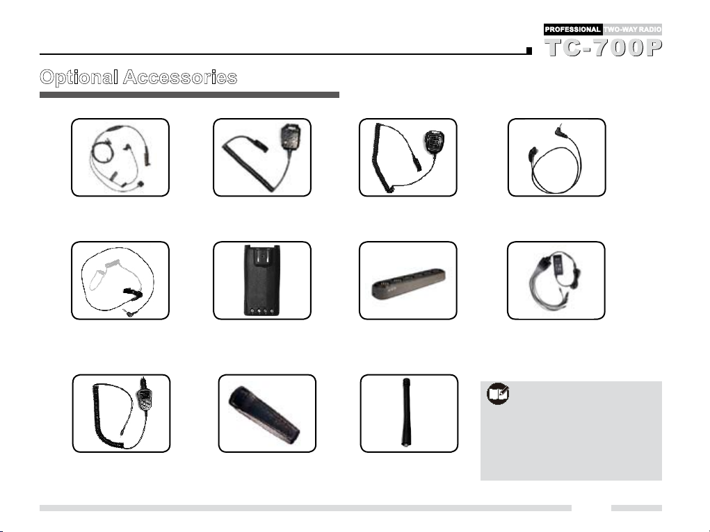
Optional Accessories
The following items are the main optional accessories for the radio, and please consult your local dealer for more other
accessories.
Earbud with on-MIC
PTT ESN06
Lightweight Single-
muff Headset ECN07
2-wire Earpiece with
Wireless Receiver and
Neck Loop EWN03
26
Earbud with In-Line
PTT ESN05
Earpiece with on-MIC PTT &
Transparent Acoustic Tube
EAN04
Noise-cancelling
Headset ECN08
D-earset with Boom
Microphone EHN08
2-wire Surveillance Earpiece with
Transparent Acoustic Tube
EAN07 (black)
Behind-the-head
Noise-cancelling
Headset ECN09
D-earset with In-Line
Microphone EHN07
Lightweight Throat-vibration
Earpiece ELN02
3-Wire Surveillance Earpiece
with Transparent Acoustic Tube
(black/beige) EAN02/ EAN06
Page 32
Optional Accessories
Bone-conduction
Earpiece EBN01
Earpiece with Transparent
Acoustic Tube (for use with
remote speaker microphone)
Vehicle Adapter
CHV09
Remote Speaker Microphone
(IP56) SM13N5
Li-Ion Battery (2100mAh)
BL2102
Ni-MH battery (1800mAh)
BH1801
Belt Clip BC09 (for use
with battery BL2102 or
BH1801)
Remote Speaker
Microphone SM08N1
MCU Multi-unit Rapid
Rate Charger (for Li-Ion/
Ni-MH batteries) MCA03
Antenna
Earbud (for use with
remote speaker
microphone) ESS07
Six-Unit Switching
Power PS7002
Note:
Use only the accessories specified by
Hytera only. If not, Hytera shall not
be liable for any losses or damages
arising out of use of unau thorized
accessories.
27
 Loading...