

Page 1

8110058000120
is the trademark of Hytera Communications Corp., Ltd.
2010 Hytera Corp., Ltd. All Rights Reserved.
Address: HYT Towe r, Hi -Tec h In du st ri al P ar k No rt h, B ei hu an
RD., Nanshan District, Shenzhen, China
Post:518057
http://www.hytera.cn
L06774 X 05 03 1
www.hytera.cn
Page 2

Preface
Thank y o u f o r p u r c h a s i n g Hy t e r a TC-580 p o r t a b l e r a d i o . It
incorporates ergo no mic design, and practical feature s s uc h a s
front panel programming and DTMF Encode & Decode. You can
conveniently customize radio settings and make calls.
To derive optimum performance from your radio, please read the
Safety Information Booklet and Owner’s Manual carefully before use.
1
Page 3

Icon Information
The following icons are available through this manual:
Caution: indicates situations that could cause
damage to your radio.
Note: indicates tips that can help you make
better use of your radio.
Term Explanation
The following terms will appear through this manual:
Key Operation
■
Short press: to press a key and release it quickly.
Long press: to press and hold down a key for above 1.5
seconds.
Hold down: to press a key and remain holding it down.
User Mode
■
Refers to the mode entered after you turn on the radio
directly.
Manual Program Mode
■
Refers to the mode entered after you turn on the radio
with both PTT and SK2 held down for 1.5 seconds.
Zone
■
Zone is a group of channels, dedicated for you to orga-
nize channels.
Zone All
■
Includes all available channels.
DTMF
■
Dual-tone multi-frequency (DTMF) signaling is used for
making selective calls, calling party identification, call
alert and etc.
CTCSS/CDCSS
■
The signaling can help you prevent unwanted conversa-
tions at the same frequency.
PTT ID
■
PTT ID, namely radio identity, allows a radio with display
and the control center to identify the calling party.
2
Page 4

Copyright Information
Hytera and CRS are registered trademarks of Hytera in
PRC and other countries and/or areas. Hytera retains
the ownership of its trademarks and product names. All
other trademarks and/or product names that may be
used in this manual are properties of their respective
owners.
Th e Hy ter a pro duc t de scri bed in t his man u al may
include Hytera computer programs stored in memory
or other media. Laws in the PRC and/or other countries
or areas preserve for Hytera exclusive rights for Hytera
computer programs. The purchase of this product shall
not be deemed to grant, either directly or by implication,
an y r igh ts t o t he p urc has er wit h re spe ct to Hytera
computer programs. Any Hytera computer programs
may not be copied, modified, distributed, decompiled,
or reverse-engineered in any manner without the prior
written consent of Hytera.
3
Disclaimer
Hytera endeavors to achieve the accuracy and com-
pleteness of this manual, but no warranty of accuracy or
reliability is given. All the specications and designs are
subject to change without prior notice due to continuous
technology development. No part of this manual may be
copied, modied, translated, or distributed in any man-
ner without the express written permission of Hytera.
If you have any suggestions or would like to learn more
details, please visit us at: http://www.hytera.cn.
Page 5

RF Energy Exposure Compliance
Your radio is designed and tested to comply with a
numbe r of national and i nternationa l standards a nd
guidelines (listed below) regarding human exposure
to radio frequency electromagnetic energy. This radio
complies with the IEEE and ICNIRP exposure limits
for occupational/controlled RF exposure environment
at oper at ing duty factors of up to 50% t ransmit ting
and is aut horized by th e F CC for occu pationa l u se
only. In terms of measuring RF energy for compliance
with the FCC exposure guidelines, your radio radiates
measurable RF energy only while it is transmitting (during
talking), not when it is receiving (listening) or in standby
mode.
Your radio complies with the following of RF energy
exposure standards and guidelines
U n it e d S t at e s F e d e r a l C o mm u n i c a ti o n s
Commission, Code of Federal Regulations; 47CFR
part 2 sub-part J
Am er ica n N ati ona l S tanda rds Insti tut e ( ANS I)/
Inst it ute of Elec trica l a nd Elect ro nic Engi neers
(IEEE) C95. 1-1992
Inst it ute of Elec trica l a nd Elect ro nic Engi neers
(IEEE) C95. 1-1999 Edition
International Commission on Non-Ionizing Radiation
Protection (ICNIRP) 1998
Operational Instructions and Training Guidelines
To ensure optimal performance and compliance with
the occu pa ti onal/controlled envi ro nm ent RF energy
exposure limits in the above standards and guidelines,
users should transmit no more than 50% of the time and
always adhere to the following procedures:
Transmit and Receive
To transmit (talk), push the Push-To-Talk (PTT) key; to
receive, release the PTT key.
4
Page 6

FCC Licensing Information
Part 15 Compliance
This equipment has been tested and found to comply
with the limits for a Class B digital device, pursuant to
part 15 of the FCC Rules. These limits are designed to
provide reasonable protection against harmful interfer-
ence in a residential installation. This equipment gen-
erates, uses and can radiate radio frequency energy
and, if not installed and used in accordance with the
instructions, may cause harmful interference to radio
communications. However, there is no guarantee that in-
terference will not occur in a particular installation. If this
equipment does cause harmful interference to radio or
television reception, which can be determined by turning
the equipment off and on, the user is encouraged to try
to correct the interference by one or more of the follow-
ing measures:
Reorient or relocate the receiving antenna.
Increase the separation between the equipment and
receiver.
5
Co n n e ct th e eq u i pm e n t in t o an out l e t on a
circuit different from that to which the receiver is
connected.
Cons ult the dea le r or an expe ri enced radio/T V
technician for help.
FCC Licensing Requirements
A license from Federal Communications Commission
is required prior to use. Your dealer will program each
radio with your authorized frequencies, signaling codes,
etc., and will be there to meet your communications
needs as your system expands. Contact your dealer for
more information.
Page 7

Contents
Checking Items in the Package -------------------- 3
Radio Overview ---------------------------------------- 4
Radio Controls -------------------------------------------- 4
Programmable Keys ------------------------------------- 5
Before Use----------------------------------------------- 7
Charging the Battery -------------------------------------
Assembly and Disassembly ---------------------------- 8
7
Status Indications -------------------------------------- 10
LCD Icons -------------------------------------------------- 10
LED Indicator ----------------------------------------------
11
Basic Operations --------------------------------------- 12
Turning the Radio On/Off ------------------------------- 12
Entering Power-on Password ------------------------- 12
Adjusting the Volume ------------------------------------ 12
Selecting a Zone ------------------------------------------ 12
Selecting a Channel ------------------------------------- 13
Inputting a Frequency ----------------------------------- 13
1
Adjusting Power Level -----------------------------------
Transmitting/Receiving a Call ------------------------- 14
Locking/Unlocking the Keypad ------------------------ 15
Menu Navigation --------------------------------------- 16
Call List ------------------------------------------------------ 16
Zone --------------------------------------------------------- 16
Settings ----------------------------------------------------- 16
Scan --------------------------------------------------------- 19
Keypad Mode ---------------------------------------------- 19
Functions and Operations --------------------------- 20
Time-out Timer (TOT) ----------------------------------- 20
Channel Scan --------------------------------------------- 20
Emergency -------------------------------------------------
Quick Call --------------------------------------------------- 22
Home Channel -------------------------------------------- 23
Display Mode Switch ------------------------------------ 23
Keypad Mode Switch ------------------------------------ 24
14
22
Page 8

Contents
Talk Around ------------------------------------------------- 24
Monitor ------------------------------------------------------ 24
Squelch Off ------------------------------------------------- 25
Compandor ------------------------------------------------- 25
Scrambler --------------------------------------------------- 26
VOX ---------------------------------------------------------- 26
Whisper ----------------------------------------------------- 27
Reverse Display ------------------------------------------ 27
Signaling Introduction --------------------------------- 28
CTCSS/CDCSS ------------------------------------------- 28
Dual Tone Multiple Frequency (DTMF) ------------- 28
Manual Program --------------------------------------- 30
CH Set ------------------------------------------------------- 31
Zone Set ---------------------------------------------------- 34
Troubleshooting ---------------------------------------- 36
Care and Cleaning ------------------------------------ 38
Optional Accessories --------------------------------- 39
Appendix: Input Method ------------------------------ 41
2
Page 9

Checking Items in the Package
Please unpack carefully and check that all items listed below are received. If any item is missing or damaged, please
contact your dealer.
Radio Unit Battery Rapid-rate Charger Power Adapter (different P/N for
(for Li-Ion battery) different countries and areas)
Antenna Belt Clip Strap Owner’s Manual /Safety Information
Booklet
Note:
The above pictures are for reference only. Actual products may vary slightly.
The antenna may vary with different frequency bands. And the frequency band is marked on the label
of antenna; if not, please refer to the label on the radio for frequency band information.
3
Page 10

Radio Overview
Radio Controls
No. Part Name
1 Strap Hole
2 Antenna
3 PTT Key
4 SK1 (programmable)
5 SK2 (programmable)
6 LCD Display
7 Function Keypad
8 LED Indicator
9 TK (programmable)
Radio On-Off/Volume
10
Control Knob
11 Microphone
12 Speaker
13 Accessory Jack Cover
14 Numeric Keypad
15
Battery Latch
16
Accessory Jack
17
Belt Clip
18
Battery
19
Charging Piece
4
Page 11

Radio Overview
Programmable Keys
For e nhanc ed con venie nce , y ou may reque st you r
de a ler to p rog r am t he k eys SK1, SK2 , an d TK as
shortcuts to the functions listed below:
Sh ort cut
No.
Keys
Adjust
1
Power
Level
2 Call 1
3 Call 2
4 Call 3
5 Call 4
6 Call 5
Compan7
dor
Display
8
Mode
Switch
Emer9
gency
5
Description
To adjust power level through
one button press.
To quickly make a call to a pre-
dened user.
For clear voice in noisy environ-
ments.
To switch display of channel
information among channel
No., channel alias and channel
frequency.
To su mmon hel p i n em erg e nt
situations.
Home
10
Channel
Keypad
11
Mode
12 Monitor
Monitor
Momen-
tary
Squelch
14
Off
Squelch
15
Off Mo-
mentary
16
Scan
Scrambler
17
VOX
18
To quickly s witch to th e Home
channel.
To quickly switch keypad entry
among frequency, channel,
DTMF, or to disable it.
To adjust the condition for incom-
ing signal match. 13
To always unmute speaker no
matter whether carrier is present
or not.
To receive signals on other chan-
nels.
To encrypt voice and thus protect
your conversations from eaves-
dropping.
The radio can automatically be-
gin to transmit when you speak.
Page 12
Radio Overview
The feature allows you to speak
19 Whisper
Reverse
20
Display
Talk
21
Around
Note: Long and short press of a key can be a
different functions by your dealer.
quietly into the radio and still be
heard clearly.
To invert display conten ts 180
degrees.
To di rec t ly comm uni cat e wit h
other radios.
6
Page 13
Before Use
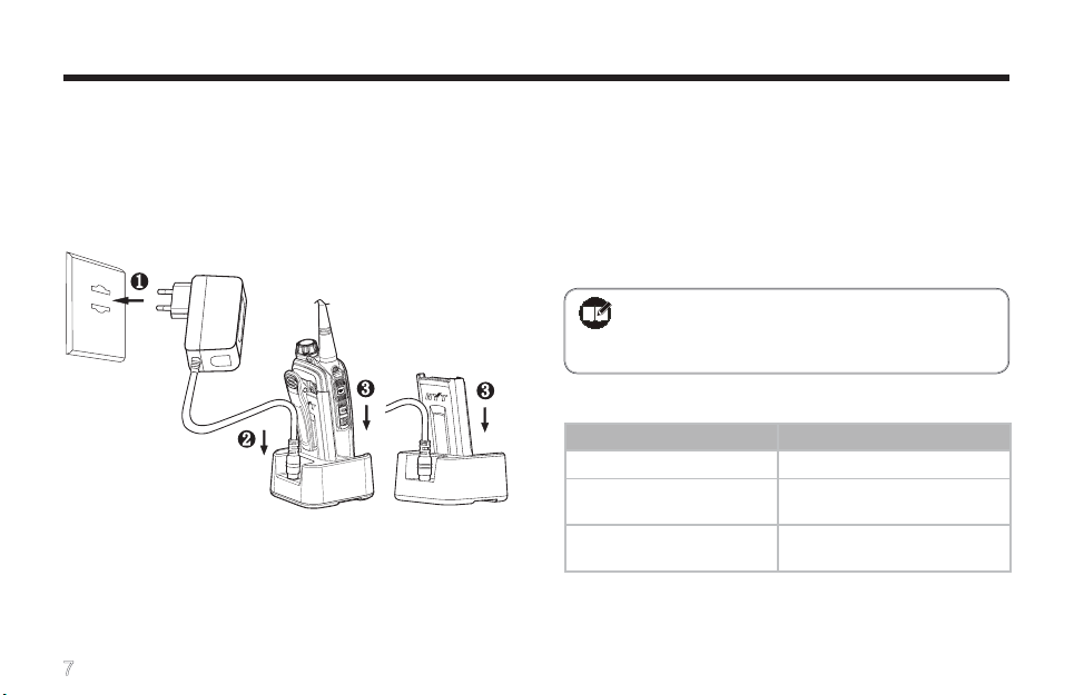
Charging the Battery
Use only the charger and battery specied by Hytera.
Charger LED can indicate the charging process.
Charge Diagram
■
Procedures
1. Co nn ect the po we r adap ter to A C s our ce. See
arrow 1.
7
2. Plug the power adapter into the rear socket of the
charger. See arrow 2.
3. Place the radio with the battery attached, or the
battery alone, into the charger. See arrow 3.
4. The charging process initiates when LED glows red,
and is completed when LED glows green.
Note: To achieve optimal battery performance,
please charge th e battery for 5 h ours
Charge Indicator
LED Indicator Charge Status
LED solidly glows red.
LED solidly glows
orange.
LED solidly glows
green.
When battery power runs low, the LED will ash red, and
the low-pitched tone will sound periodically. In this case,
please replace or charge the battery.
before initial use.
Charging
90% charged
Idle or charge completed
Page 14

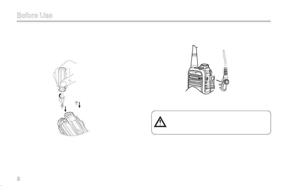
Before Use
Note: Be sure to read the Safety Information
Booklet, to get necessary safety informa-
tion.
Assembly and Disassembly
Attaching the Antenna
■
Turn the antenna clockwise to fasten it.
To remove the antenna, rotate it counter-clockwise.
Attaching the Battery
■
1. Press the belt clip and slide the battery into the
radio’s slot.
2. Slightly press the bottom of the battery until a click
is heard.
To r em ov e t he batt er y, turn off the radi o first. Then
press the belt clip, and slide the battery latch upward to
release the battery.
8
Page 15
Before Use
Attaching the Belt Clip
■
1. Remove the screws.
2. Align the screw holes on the belt clip with those on
the radio’s body, and then tighten the screws.
To remove the belt clip, loosen the screws.
Attaching Accessories
■
1. Open the accessory jack cover.
9
2. Plug an accessory into the accessory jack, and then
tighten the screw.
To remove accessories, loosen the screw rst.
Caution: When you are using an external
accessory, waterproof performance of the
radio may get affected.
Page 16
Status Indications
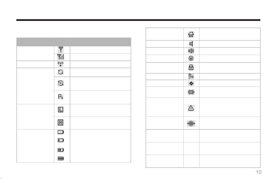
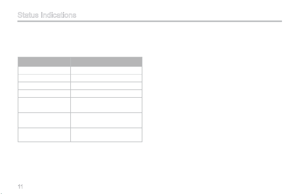
LCD Icons
Icon Name Icon Description
RSSI
Transmit Icon Transmission is in progress;
Scan Icons
Transmit Power
Icons
Battery Strength
Icons
There is no signal;
There is signal for receiving;
Scanning is in progress;
Scanning pauses on a non-
priority channel;
Scanning pauses on Priority
Channel 1;
The current channel is oper-
ating at low power;
The current channel is oper-
ating at high power;
More bars indicate more bat-
tery power;
Ho m e C han n el
Icon
Monitor Icon Monitor function is active;
Squelch Icon Speaker is unmuted;
VOX Icon VOX function is active;
K e y p ad L oc k
Icon
Whisper Icon Whisper function is active;
Scrambler Icon Scrambler function is active;
Compandor Icon
Emergency Icon
Talk Around Icon
CTCSS Icon CT
CDCSS Icon DT
DTMF Icon DF
The radio stays on a Home
channel;
The keypad is locked;
Compan do r funct io n is ac-
tive;
The Emergency function is
active or an emergency alarm
is received;
Talk Aroun d function is ac -
tive;
TX/RX CTCSS is pro-
grammed on current channel;
TX/RX CDCSS is pro-
grammed on current channel;
TX/RX DTMF is programmed
on current channel.
10
Page 17
Status Indications
LED Indicator
The top LED indicator will help you easily identify the
current status of your radio.
LED Indicator Radio Status
Red LED glows. Transmitting
Red LED ashes. Low battery alert
Green LED glows. Receiving
Green LED ashes. Scanning
Orange LED glows.
Orange LED ashes
slowly.
Orange LED ashes
rapidly.
11
A call is transmitted (within
the Auto Reset Time)
A call is received (within the
Auto Reset Time)
A call is missed
Page 18
Basic Operations
Turning the Radio On/Off
Rota t e t h e Ra d i o On-Off/Volume Co n t r o l kn o b
clockwise/counter-clockwise until a click is heard to turn
the radio on/off.
Entering Power-on Password
You may go to the menu “Settings->PowerOn PSW” to
set the password on or off. See PowerOn PSW on page
18 for more details.
After you input the passwor d, press to confirm.
Then a power-on alert tone will sound, and the home
screen will appear. However, if the password is incor-
rect, the display will show “Error”, prompting you to enter
the password again.
Note:
When PowerOn PSW is set on, you will
be required to input the password to turn
on the radio.
The password is programmable by your
dealer, and may contain up to 8 digits.
Adjusting the Volume
You may adjust call volume through the knob. Rotate
the knob clockwise to increase the volume, or counter-
clockwise to decrease the volume.
To adjust volume for alert tones or warning tones, go to
the menu “Settings->Alert VOL / PowerOn VOL / Key
VOL / Warning VOL” (See Settings on page 16 for more
details).
Selecting a Zone
The radio supports up to 32 zones. You may choose
to operate in a single zone, or choose Zone All so you
12
Page 19
Basic Operations
can access all the available channels. You may select a
zone through any of the following methods:
You may quic kl y t og gle to your desired zone,
through press of the p rogrammed Zone Up or
Zone Down key; or
Go to the menu “Zone”, press / to select
your desired zone, and then press to conrm.
Note: You m ay i ncl u de chan nel s in a z one
in Manual Program mode, or ask your
dealer to include them in a zone.
Selecting a Channel
The radio supports up to 256 channels. You may select
a channel through any of the following methods:
Press / to select your desired channel; or
When the keypad input mode is set to Channel,
directly enter the channel No., and then press
13
to switch to the channel (see Keypad Mode
Switch on page 24 for more details); or
Press the programmed Home Channel key to
quickly switch to the Home channel (See Home
Channel on page 23 for more details).
Inputting a Frequency
You can manually input a desired frequency within the
frequency band of your radio, to transmit and receive
calls. Operations:
1. Select Frequency from the menu “Keypad Mode”,
and press .
2. Retu rn to the home scr een , i nput you r desi red
freq uency throu gh the keypad, and pr es s .
B y w a y o f i l l u s t r a t i o n , t o i n p u t f r e -
q u e n c y 3 6 5 . 6 5 0 0 0 M H z , j u s t p r e s s
t h e f o l l o w i n g k e y s o n e b y o n e :
+ + + + + +
Page 20

Basic Operations
Then the entered frequency will appear on the home
screen, and you can transmit and receive on the fre-
quency.
Note:
The entered frequ ency will be saved if you
turn the radio off and back on, but will not be
saved if you change channel. It will be used
for both transmitting and receiving. However,
other channel parameters such as TX power
and channel spacing will remain unchanged.
To save the frequency permanently or to cus-
tomi ze other chann el param eters, enter the
Manual Program mode and go to “CH Set” (See
CH Set on page 31 for more details).
If you enter a frequency out of the frequency
band, the LCD will display “Out of Range”. If
the entered freque ncy is not compliant with
the rule, the radio will display a valid frequency
closest to it.
This function may not be available in certain
countries or regions. Please contact your local
dealer for more information.
Adjusting the Power Level
Generally, we recommend you to adopt low power for
battery saving. However, if you cannot communicate
with radios located at a distant place with low power,
please select high power. Operations to change power
level:
Press the programmed Adjust Power Level key
to switch between high and low; or
Enter the Manual Program mode, and go to “CH
Set->Option Items->Power Level”, to select high
or low power (See Power Level on page 33 for
more details).
The home screen shows the icon for high power, and
for low power.
Transmitting/Receiving a Call
To transmit a call, press and hold down the PTT, and
speak into the microphone. During transmitting, the LED
solidly glows red, and the icon appears on the dis-
play.
14
Page 21

Basic Operations
To receive, just release the PTT. When a signal is re-
ceived, the LED solidly glows green, and the icon
appears on the display.
Note:
To ensure optimal volume of the receiving
radio, hold the radio approximately 2.5 to
5 centimeters away from your mouth.
Communication range may get affected
in rainy days or forest locations.
Locking/Unlocking the Keypad
Locking the keyp ad can prevent acciden ta l k eypad
operation.
To lock or unlock the keypad, press and then
immediately.
15
Note: When the k eypad is lock ed, the radio
can also respond to the keys PTT, SK1,
SK2 and TK.
Page 22

Menu Navigation
Radio S et Menu
Call
List
Zone
Settings
Scan
Keypad
Mode
MENU 1/5
◄Call List ►
MENU 2/5
◄Zone ►
MENU 3/5
◄Settings ►
On the home screen, press to access the main
menu. Then press / to select a menu option
from Call List, Zone, Settings, Scan, and Keypad Mode.
ID, or press the PTT to transmit a call to the pre-dened
user.
Zone
This menu allows you to select a zone.
Settings
Call List
The radio supports up to 32 call lists. Under this menu,
you may select a target contact, and then edit its alias or
You can optimize your radio performance by customizing
related parameters according to actual needs and your
preferences.
This menu includes the following sub-menus:
16
Page 23
Menu Navigation
VOX Gain
■
To select a VOX gain level.
Available options Off / Level 1 / Level 2 / Level 3 / Level
4 / Level 5
Key Lock
■
The keypad will be locked automatically after the time
set for the Key Lock option elapses.
Available options: Off / 5s / 10s / 15s / 30s / 60s
Note: Hi gher g a in l e v el r e p rese n t s hi g h er
sensitivity. If this option is set to Off, the
VOX feature will not work even i f it is
enabled.
SQL
■
To select an appropriate squelch level.
Available options Open / Level 1 / Level 2 / Level 3 /
Level 4 / Level 5 / Level 6 / Level 7 / Level 8 / Level 9
Note: Higher squelch level requires stronger
sign al for the r ad io to unm ute. If thi s
option is set to Open, the radio will keep
unmuted irrespective of the satisfaction
17
Note: If this option is set to Off, the keypad will
not get locked automatically.
Backlight
■
To set the time duration that the backlight will keep lit.
Available options: Off / Innite / 5s / 15s / 30s / 60s
Note: If this option is set to Off, the backlight
will always remain disabled. If it is set
to I n fini t e , th e backl i g h t wi l l rema i n
illuminated all the time.
Alert VOL
■
To set the volume level for alert tone (decoding alert).
Available options: Off / Level 1 / Level 2 / Level 3 / Level
4 / Level 5
Page 24

Menu Navigation
Note: Higher level represents higher volume. If
this option is set to Off, the radio will not
sound decoding alert tone.
PowerOn VOL
■
To set the volume level for power-on alert tone.
Available options: Off / Level 1 / Level 2 / Level 3 / Level
4 / Level 5
Note: Higher level represents higher volume. If
this option is set to Off, the radio will not
sound power-on alert tone.
Key VOL
■
To set the volume level for key press alert such as front
panel key press alert, error alert, TX inhibit alert and
cycle alert.
Available options: Off / Level 1 / Level 2 / Level 3 / Level
4 / Level 5
Note: Higher level represents higher volume. If
this option is set to Off, the radio will not
sound the above key-press alert tones.
Warning VOL
■
To se t t he v olu me lev el f or war nin g tone s su ch as
function on/off alert, TOT alert, low battery alert and
priority channel alert.
Available options: Off / Level 1 / Level 2 / Level 3 / Level
4 / Level 5
Note: Higher level represents higher volume. If
this option is set to Off, the radio will not
sound warning alert tone.
PowerOn PSW
■
To set whether power-on password is required for you to
turn the radio on.
Available options: On/ Off
18
Page 25

MENU 4/5
◄Scan ►
MENU 5/5
◄Keypad Mode ►
Menu Navigation
Note: If no power-on password is set by your
dealer, this menu option will be invalid.
CH Display
■
To select the channel information to be displayed on the
home screen.
Available options: Number/ Frequency/ Alias
Radio Info
■
To view some radio information.
Available information: Firmware Ver / SN
Scan
To set Scan on or off.
19
Keypad Mode
To select keypad entry mode.
Available options are:
Disabled:To disallow entry through the keypad.
Channel:You can input channel number through the key-
pad.
DTMF:You can input DTMF code through the keypad.
Frequency: You can input frequency through the keypad.
Note: Thi s f un ct io n m ay not be a vailable in
ce r tai n cou ntri e s o r reg ions . Pl e ase
cont a c t yo u r lo c a l de a ler fo r mo r e
information.
Page 26
Functions and Operations
Time-out Timer (TOT)
The purpose of TOT is to prevent any user from occupy-
ing a channel for an extended period. When the preset
time expires, the radio will automat ic ally ter minate
transmission and keep beeping. To stop beeping, please
release the PTT key. You must wait for a certain time
period (preset by your dealer) to initiate another trans-
mission.
If the Pre-alert function is activated by your dealer, your
radio will alert you to the TOT expiration in advance.
Note: This feature is null in Emergency mode.
Channel Scan
This feature allows you to listen to communication ac-
tivities on other channels so that you can keep a close
track of your team members.
The scan list can be set by your dealer, and a maximum
of 32 channels are allowed for each scan list.
Operation:
1. T o a c t i v a t e t h i s f u n c t i o n , p r e s s
t h e p r o g r a m m e d S c a n k e y ; o r
s e l e c t “ O n ? ” f r o m t h e m e n u
“ S c a n ” , p r e s s t o c o n f i r m ; o r
switch to a channel with Auto Scan feature enabled
(programmed by your dealer).
2. After scan is enabled, the radio will sound an alert
tone (programmed by your dealer), and begin to
sc an t he p rog ramm ed s can lis t. The sca n nin g
process is as follows:
During scanning, LCD displays icon , and LED
ashes green.
When communication activities are detected on
a channel, o r the pro grammed Monitor key is
pressed, or the PTT is pressed to transmit, the
radio will st ay to re ce iv e activities present on
this channel. If your radio stays on a non-priority
20
Page 27
Functions and Operations
channel, the LCD will display ; if it stays on
Priority Channel 1, the LCD will display
If the Talk Back feature is enabled by your dealer,
press the PTT to reply when the radio stays on a
certain channel.
You can scan the frequently used Priority Channel
(only one Priority Channel allowed). When staying
on a non -p riori ty chann el, the rad io will kee p
detecting activities on the priority channel. Once
any activity is detected, it will jump to the priority
ch a nnel imme d iate l y. Fo r mor e inf o rmat i on,
please contact your dealer.
3. T o e x i t t h e s c a n n i n g p r o c e s s ,
p r e s s t h e S c a n k e y a g a i n ; o r
select “Off?” from the menu “Scan”, and press
to conrm. When exiting from Scan mode, the radio
will also sound an alert tone (programmed by your
dealer) and the icon disappears.
.
21
Methods to Exit Scanning
Besides the above methods, you can exit scanning in
the following ways:
Switch to a channel where Auto Scan feature is
not enabled;
Press one of the programmed Call1-Call5 keys;
Select a target contact from the menu “Call List”,
and press PTT;
Enable the Emergency function;
Turn the radio off.
Note:
During scanning, the following functions
can not be enabled: Power Adjust, Com-
pandor, Scrambler, Whisper, Talk Around
and Keypad Mode Switch.
To ensure a quick scan, the adjacent chan-
nel spacing should not exceed 30MHz.
Page 28

Functions and Operations
Emergency
In case of an emergency, you can use this feature to ask
for help from your companion or the control center.
Emergency Start
■
Press the programmed Emergency key to trigger this
function (the icon appears).
Emergency Exit
■
Th e ra d io wi l l re t u r n to th e pr e v i o us op e r ati n g
channel after exiting from Emergency mode (the icon
disappears).
Ways to exit from Emergency mode include:
1. Long press the programmed
2. The emerg en cy cyc les (prog ramme d by your
dealer) expires; or
3. Turn the radio off.
Emergency Mode
■
Once the radio enters Emergency mode, it will switch
Emergency key; or
to the preset Emergency Revert Channel. A complete
process includes four stages: 1) Transmit the ID; 2)
Transmit the alarm; 3) Transmit the background tone;
and 4) Forcibly receive. The cycles and duration of each
stage can be programmed by your dealer. Please ask
your dealer to program one of the following Emergency
modes:
1. No alarm tone sounds;
2. The alarm tone can be heard by the transmitting
party only;
3. The alarm tone can be heard by the rece iving
party only ;
4. The alarm tone can be heard by both parties.
Quick Call
This feature allows you to call other radios quickly.
Operation:
Press the programmed Call1-Call5 key, which is
assigned with a unique radio ID respectively; or
22
Page 29

Functions and Operations
Select the target ID through the menu “Call List”,
and press PTT.
Note: Ple as e r equest your dea le r to a ssign
your desired radio IDs to Ca ll 1- Ca ll 5
respectively.
Home Channel
This feature allows you to switch to the Home channel,
namely, the most frequently used channel. It can be
programmed by your dealer. This radio supports one
Home channel only.
Operation:
Press the programmed Home Channel key to switch to
the predened Home channel ( appears on the LCD).
To return to the previous non-home channel, press this
key again (the icon disappears).
23
Note: If the Auto Reset Timer is enabled by
your dealer, the radio will automatically
switch to the Home channel when the
timer expires and there is no operation
(like key-press, transmitting or receiving
operations)
Display Mode Switch
This feature allows you to select the channel information
to be displayed on the home screen. The following three
options are available: Number, Alias and Frequency. For
example, if you choose Number, the home screen will
display the number of your current channel.
Operation:
Press the programmed Display Mode Switch key
to switch the mode; or
Select your desired display mode through “CH
Display” under the menu “Settings”, and press
to conrm.
Page 30
Functions and Operations
Keypad Mode Switch
This feature allows you to choose one of these keypad
input modes: Disabled, Frequency, Channel and DTMF.
Operation:
Pres s the p ro gra mmed Key pad Mode key to
switch the keypad input mode; or
Select your desired keypad input mode through
the m e n u “Ke y p a d Mode” , a n d pres s t o
conrm.
Note: This func ti on may not be available in
ce r tai n cou ntri e s o r reg ions . Pl e ase
cont a c t yo u r lo c a l de a ler fo r mo r e
information.
Talk Around
This feature allows you to continue communication even
when the repeater malfunctions, or when your terminal
is out of the repeater’s range but within the coverage
range of another terminal.
Operation:
Press the programmed Talk Ar ound key to activate
this function ( appears and an alert tone sounds).
To deactivate this function, just press it again, or switch
to another cha nnel, or po wer the rad io off (t he icon
disappears and the alert tone sounds twice).
Monitor
This featu re all ows you t o lowe r t he con dit ions for
incoming signal match.
Operation:
Pr e ss t h e pr o gram m ed M o nito r key to a c ti-
vate this function ( appears and an alert tone
sounds); press it again to deactivate the function
(the icon disappears and the alert tone sounds
twice). Or
Pr e s s an d h ol d the pr ogr a m m ed Mo ni t o r
Mo m e ntar y key t o ac t ivat e this f unct i on (
appears and an alert tone sounds); release the
24
Page 31
Functions and Operations
key to exit (the icon disappears and the alert tone
sounds twice).
Note: I n A u to R e se t m o d e , p re s s t h e
p r og ra m me d Mo n it or o r M o n i to r
Momentary key to cancel a call.
Squelch Off
This feature allows you to unmute the speaker to receive
all audio signals on current channel.
Operation:
Press the programmed Squelch Off key to acti-
vate this function ( appears and an alert tone
sounds); press the key again to deactivate it (the
icon disappears and the alert tone sounds twice).
Or
Press and h old the programme d Squelch Off
Momentary key to activate this function ( ap-
pears and an alert tone sounds); release the key
to deactivate it (the icon disappears and the alert
tone sounds twice).
25
Note:
I n Au to R e s e t mo d e , pr e ss i n g t h e
programmed Squelch Off or Squelch Off
Momentary key would cancel a call.
When this function is enabled on current
channel, you will hear audio signals (if any);
otherwise, background noise will be heard.
Compandor
This feature may suppress ambient noise and improve
audio quality, allowing you to hear clear and crisp voice
even in noisy environment.
Operation:
Press the programmed Compandor key to activate this
function ( appears and an alert tone sounds); press
the key again to deactivate it (the icon disappears and
the alert tone sounds twice). Or
Page 32

Functions and Operations
Note: This function can be enabled or disabled
on a designated channel by your dealer.
Scrambler
Th i s fe atu r e c an en c r ypt yo u r au d i o si g n a l s to
prevent e av esdropping. Thus priv ac y o f your voice
communication is guaranteed.
Operation:
Press the programmed Scrambler key to acti-
vate this function ( appears and an alert tone
sounds); press the key again to deactivate it (the
icon disappears and the alert tone sounds twice).
Or
Switch to a channel programmed with this feature
by your dealer; exiting from this channel would
deactivate the function.
Note: This function may vary with different ra-
dio models.
This function may not be available in cer-
tain countries or regions. Please contact
your local dealer for more information.
VOX
This feature allows you to transmit the voice with no
ne e d to p ress PTT. H owev e r, you m ust e mplo y a
dedicated earpiece to realize this function.
Operation:
1. Set the
2. Plug the earpiece into the accessory jack;
3. Press the programmed
4. Speak into the microphone (o n the ear piece) t o
PTT/VOX Switch on the earpiece to VOX;
VOX key to activate this
function ( appears on the LCD);
tran smit you r v oice, and t ransm issio n w ill stop
automatically when you stop talking;
26
Page 33

Functions and Operations
5. Power the radio off or press the VOX key again to
deactivate this function.
Note:
If the PTT/VOX Switch on the earpiece
is set to PTT, you can on ly tra nsm it by
pre s s i n g th e externa l P T T , no matter
whether VOX is activated.
When the PTT/VOX Switch is set to PTT,
you are not allowed to switch it from PTT
to VOX di rec tly ; ot her wis e, con tinu ous
tr a nsmi ssio n may occu r. If c onti n uou s
transmission occurs unexpectedly, you can
restore the radio to normal operation by
toggling the switch from VOX to PTT, or
turning the radio off and back on.
Yo u ca n se l e ct an ap pr o p r ia t e VO X
sensitivity according to the environment. If
there are heavy noises, you’d better select
a lower VOX sensitivity.
27
Whisper
With this feature , even if you speak with a very low
voice, it can still be heard clearly by the receiving party.
Operation:
Press the programmed Whisper key to activate this
function ( appears and an alert tone sounds); press
the key again to deactivate it (the icon disappears and
the alert tone sounds twice).
Reverse Display
With this fea tur e, the display ed inf or mat ion on th e
display can be rotated by 180 degrees.
Operation:
Press the programmed Reverse Display key to rotate
the displayed information by 180 degrees (an alert tone
sounds); press this key again to restore the display (an
alert tone sounds twice).
Page 34

Signaling Introduction
CTCSS/CDCSS and DTMF signalings are available with
TC-580. For detailed information, please contact your
dealer.
CTCSS/CDCSS
CDCSS/CTCSS can be used to prevent unwanted con-
versations at the same frequency. If CTCSS/CDCSS
is set on a certain channel, you can only receive voice
calls from radios with matching CTCSS/CDCSS. Other-
wise you will receive voice calls from all users operating
at the same frequency.
You may request your dealer to program corresponding
parameters; alternately, you can program them manu-
ally through your radio by yourself. For more informa-
tion, please refer to the section “RX CTC/CDC” and “TX
CTC/CDC” in Manual Program on page 32.
Dual Tone Multiple Frequency (DTMF)
Methods to transmit DTMF signaling:
1. Enter the menu Call List, select your desired contact
entry, and press PTT to transmit; or
2. Press the programmed
or
Note: To enable this feature, DTMF signaling
must be enabled on current channel via
3. Enter the DTMF code on the home screen, and then
press PTT to transmit.
Note: The D TMF code is co mprised of 0-9,
A-D, * and #.
During transmission, the LED glows red solidly; after
transmission, it soli dly glows orange within the auto
reset time (programmed by your dealer).
Decoding DTMF signaling:
Wh e n a chan n el i s pr o gra m med t o r e ceiv e DT M F
sig n a l i n g , the radio w i l l de c ode mat c h i n g DT M F
signaling only.
When the radio is receiving DTMF signaling, the LED
gl o ws g ree n so l idl y ; a f ter it s ucc e ssf u lly rec e ive s
Call1-Call5 key to transmit;
28
Page 35
Signaling Introduction
the sig na ling, the L ED keeps flas hing ora ng e for a
predened time period.
When an Emergency alarm is received
The rad io will sou nd a fixe d E mergenc y a lert
tone when it receives an Emergency Alarm (an
Emergency ID should be programmed at rst).
When an individual call is received
The radio will sound a personalized alert tone
when it receives an Individual Call (an Individual
Call ID should be programmed at rst).
When a group call is received
The radio will sound a personalized alert tone
when it receives a Group Call (a Group Call ID
should be programmed at rst).
When calls of other types are received
If the radio is programmed to display IDs, such
IDs will be displayed on the LCD when calls of
other types are received.
Types of Response
Your radio may be set to give any of the following
29
types of response, when it receives an individual
call or group call:
1) The radio gives no response.
2) Silent A lert: The L CD will dis play “Aler t C all
Received”, but no sound alert will be given.
3) Sound Alert: The L CD will display “A lert Call
Received” with sound alert, and only the sound
alert will automatically reset.
4) Select Call Alert: The LCD will display “Select
Call Received” with sound alert. Both the sound
alert and displayed text will automatically reset.
AC K (Ackno w l e dge) : If the AC K featur e is
enabled, the radio will send back a single tone or
its PTT ID to the calling party when it receives an
individual call or group call.
Note: Please request your dealer to program
the individual call ID, group call ID and
emergency call ID, as well as response
method, ID display feature and ACK fea-
ture of DTMF decoding.
Page 36

Manual Program
The radio supports convenient programming of zone and channel related parameters from the front panel.
However, this function may not be available in certain countries or regions. Please contact your local dealer for more
information.
To enter the Manual Program mode:
Rotate the Radio On-Off/Volume Control knob, with both PTT and SK2 held down for above 1.5 seconds, to turn the
radio on. Then the radio will enter the Manual Program mode. When “Manual Program” appears on the LCD, press
to begin settings of parameters.
30
Page 37
Manual Program
Manual PROG 1/2
◄CH Set ►
CH Set
The CH Set menu allows you to add or delete channels,
and set channel parameters and features.
Operations:
Select CH Set and press . Then press / to
select a channel one by one, or press / to
scroll by page (each page includes ten channels). The
radio supports up to 256 channels. Under the CH Set
menu, specic channel No. will be displayed for existing
channels, while “CH - -” will be displayed for non-existing
channels. Available operations:
Delete a channel:
press . Then the LCD will give a prompt “Del CH?”.
You may press to delete this channel, or press
to cancel.
31
se l e ct a n exi s t ing c hann e l , an d
Note: After you delete a channel,
You cannot select the deleted channel
for use.
If the deleted channel is the designated
Powe r-o n c han nel or Home cha nne l,
th e de signa t i on wi l l becom e in vali d
automatically.
If the deleted channel is a designated
Revert Channel, signaling transmission
on the channel will fail.
If t h e de leted c h a n n e l is a m e m b e r
included in the scan list, it will be ignored
during scanning. If all channels in the
scan list are deleted, you will be unable
to activate scanning.
If all channels in a zone are deleted, the
radio will alert you of an empty zone and
sound warning tone.
Page 38

Manual Program
Add a channel: sel e c t “C H - -” -> pr e s s ->
select “RX Freq” -> press -> enter the RX frequency
(see Inputting a Frequency on page 13 for the method to
input a frequency) -> press . Then the channel will
be added successfully.
Note: You must enter a valid RX frequency to
add a channel.
Edit parameters:
-> press / to select the option to set ->
press to set. Available parameters are:
RX Freq
■
To set t h e RX f r e quen c y for t h e cu r r e nt c h a nnel.
Operations:
1. Press
select an existing channel -> press
, and then enter the RX frequency.
2. Press to save it.
TX Freq
■
To s et th e TX fr e q u ency f o r the c u r rent c h a n nel.
Operations:
1. Press
2. Press
RX CTC/CDC
■
You can set RX CTCSS/CDCSS signaling to CTC/CDC
None, CTC, Normal CDC, or Invert CDC, and you can
also customize the signaling. Operations:
1. Select RX CTC/CDC -> press
/ to select the desired signaling type -> press
2. Press
, and then enter the TX frequency.
to save it.
-> press
to customize the signaling.
to save the signaling.
32
Page 39
Manual Program
TX CTC/CDC
■
You can set TX CTCSS/CDCSS signaling to CTC/CDC
None, CTC, Normal CDC, or Invert CDC, and you can
also customize the signaling. Operations are the same
as that in “RX CTC/CDC”.
Note: If CTCSS/CDCSS signaling exceeds the
following range, your radio performance
will not be guaranteed.
Rec o m me n d ed ra n g e fo r CT C SS :
67Hz~254.1Hz
Rec o m m en d e d ra n g e f o r CD C S S :
023~754
Option Items
You ca n cu s t o m i z e c h a n n e l related pa r a m e t e r s
ac c o rdin g to a c t ual n e eds a nd y o u r pr e f eren c e s.
Available parameters are:
33
CH Spacing
To set channel spacing to wide or narrow.
Available options: Wide/ Narrow
Power Level
To set TX power level.
Available options: Low/ High
Whisper
To enable or disable the Whisper feature.
Available options: Disabled/ Enabled
Compandor
To enable or disable the Compandor feature.
Available options: Disabled/ Enabled
Scrambler
To enable or disable the Scrambler feature.
Available options: Disabled/ Enabled
Page 40

Manual PROG 2/2
◄Zone Set ►
Manual Program
Alias
To set the alias for the current channel. Operations:
1. Press
acters).
2. Press
and then enter the alias (up to 10 char-
to save the alias.
Zone Set
This menu allows you to add or delete zones and chan-
nels.
Operations:
Select Zone Set and press . Then press / to
select a zone one by one, or press / to scroll
by page (each page includes ten zones). The radio sup-
ports up to 32 zones. Under the Zone Set menu, specic
zone No. will be displayed for existing zones, while “Zone
- -” will be displayed for non-existing zones. Available
operations:
Delete a z o n e : y o u ca n d e l e t e a n existing zo n e
b y d e l e ti n g al l c h an ne l s in c lu d ed i n i t . Th e
d e l et e d z o n e wi l l be di s p la y e d as “Z o n e - -“ .
Select an existing zone -> press -> press to
select “Del CH” -> press -> press repeatedly to
delete all channels in the current zone.
Note: You cannot select an empty zone in User
Mode.
A d d a z o n e : Yo u c a n a d d a z o n e b y a d d -
i n g o n e o r m o r e c h a n n e l s i n t o i t .
Select “Zone - -” -> press -> press (when “Add
CH” appears) -> press / to select a channel
34
Page 41
Manual Program
and then press to add it. You may repeat the last
step to add more channels.
Edit a zone:select an existing zone -> press ->
press / to select “Add CH” or “Del CH”.
Add CH
You may add channels to the current zone. Operations:
1. Press
2. Press
able channel).
/ to select a channel to add.
to add it (LCD will display the next avail-
Note: I f t h e cu r rently s e l e c t e d channel i s
already included in the zone, the LCD
will give you a prompt.
35
Del CH
You m a y delet e ch annel s f r om th e c u rrent z o n e .
Operations:
1. Press
2. Press
available channel).
/ to select a channel to delete.
to delete it (LCD will display the next
Page 42

Troubleshooting
Phenomena Analysis Solution
The radio can not be
powered on.
During receiving signals,
the voice is weak,
discontinuous or totally
inactive.
The battery may be improperly in-
stalled.
The battery may have run out. Recharge or replace the battery.
The battery may suffer from poor
contact caused by dirtied or damaged
battery contacts.
The battery strength may be too low. Recharge or replace the battery.
The volume may be set to a low level. Increase the volume.
The antenna may get loose or may be
improperly installed.
The speaker may be blocked or dam-
aged.
Remove the battery and attach it again.
Clean the battery contacts. If the problem
can not be solved, contact your dealer or our
authorized service center for inspection and
repair.
Power off the radio, re-install the antenna and
power on the radio again.
Clean surface of the speaker. If the problem
can not be solved, contact your dealer or our
authorized service center for inspection and
repair.
36
Page 43

Troubleshooting
The frequency or signaling may be in-
You can not communi-
cate with other members.
Irrelevant communication
activities or noises are
heard on the channel.
The noise is too loud.
If the above solutions can not x your problems, or you may have some other queries, please contact us or your local
dealer for more technical support.
consistent with that of other members.
You may be too far away from the
group members.
You may be interrupted by radios using
the same frequency.
The radio may be set with no signaling.
You may be too far away from other
members.
You may be at an unfavorable position.
For example, your communication may
be blocked by high buildings or frustrat-
ed in the underground areas.
You may suffer from external distur-
bance (such as electromagnetic inter-
ference).
Set your frequency and signaling to the same
as that of other members.
Move towards other members. And make sure
that you are within the communication range.
Change the frequency, or adjust the squelch
level.
Set signaling for all member radios to avoid
interference at the same frequency.
Move towards other members, power off your
radio and then restart it.
Move to an open and at area, and restart the
radio.
Stay away from equipment that may cause
interference.
37
Page 44

Care and Cleaning
To guarantee optimal performance as well as a long ser-
vice life of your radio, please follow the tips below.
Radio Care
Keep the radio far away from substances that can
corrode the circuit.
Do not hold the radio by its antenna or earpiece
cable directly.
Attach the accessory jack cover when the radio is
not in use.
Radio Cleaning
Clean up the dust and fine particles on the radio
surface and charging piece with a clean and dry lint-
free cloth or a brush regularly.
Use n e u t ral cl e a n s e r and a n o n - woven c l o t h
to cle an the keys, con trol knobs and fro nt case
regularly. Do not use chemical preparations such as
stain removers, alcohol, sprays or oil preparations,
so as to avoid surface case damage. Make sure the
terminal is completely dry before use.
Caution: Power off the radio and remove the
battery before cleaning.
38
Page 45

Optional Accessories
The following items are the main optional accessories for the radio, and please consult your local dealer for more acces-
sories.
Li-Ion Battery (1100mAh)
BL1102
Li-Ion Battery (1300mAh)
BL1301
Ear b u d with on - M I C
PTT & VOX ESM12
39
Ve h i c l e A d a p t e r f o r
Charger CHV09
D-ea r s e t wi t h Boo m
MIC & VOX EHM16
S i x - u ni t Sw it ch i n g
Po w er P S 7 002 ( The
power cable may vary
in diff erent countri es
and areas)
D- ear set with i n-L ine
MIC & VOX EHM15
Earbud w i t h i n - L i n e
PTT & VOX ESM11
Earpiece with on-MIC
PTT & V OX& Trans-
parent Acoustic Tube
EAM12
Page 46

Optional Accessories
Remote Speaker Mi-
crophone SM08M3
Note: Use o nl y the acces so ries spe ci fied by
Hytera only. If not, Hytera shall not be li-
able for any losses or damages arising out
of use of other unauthorized accessories.
R e ce iv e- O nl y Ea r -
piece with Transparent
Acoustic Tube (for use
wit h re mote s p e aker
microphone) ESS08
Receive-Only Earbud
(f o r u s e w i th r emo t e
spe aker micro phone)
ESS07
40
Page 47

Appendix: Input Method
You can enter channe l n umber, alia s, frequ en cy or
DTMF code using the keypad. This radio supports the
following input methods: Number (“123”) and English (
“ABC”/”abc”).
Use the following keys as instructed:
Key Function
/
To move the cursor.
To conrm your entry.
-
To delete the characters.
I n E n g l i sh in p u t m e t h o d , p r e s s
t h is k e y r e p e at ed l y t o en t er “# ”
, “ 1 ” an d p u nc tu a ti on s i n or d er ;
In Number input method, press this key
to enter “1”.
To enter the number or letter born on the
key.
41
In English input method, press this key
to enter a space, and double press it to
enter “0”;
In Number input method, press this key
to enter “0”.
In English input method, press this key to
enter “*”, and double press it to enter “.”;
In Number input method, press this key
to enter “*”.
To switch the input method.
English Input Method
The 26 letters are distributed among the alphanumeric
keys 2~9. Press the key which bears your desired let-
ter repeatedly until the letter appears. If the next letter
Page 48
Appendix: Input Method
is also located on the present key, wait until the cursor
moves to the next entry position, and then input the let-
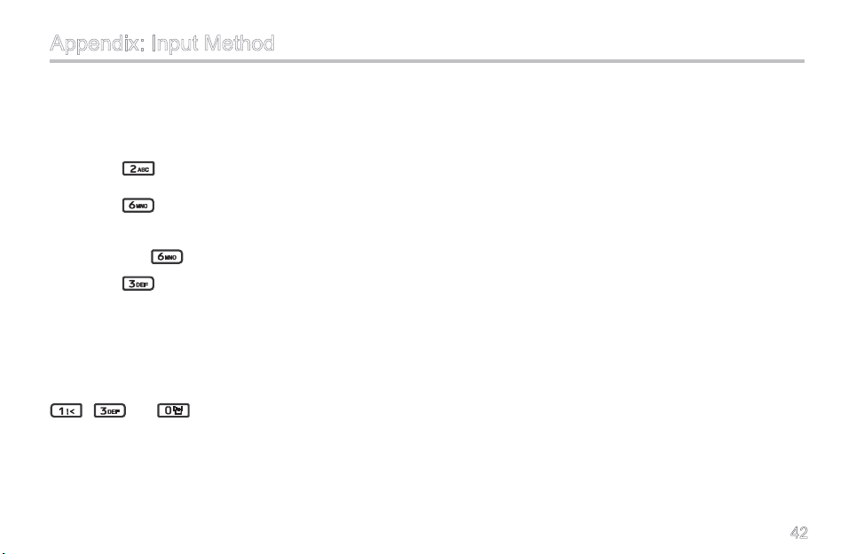
ter. For example, to input the word “come”:
1. Press
repeatedly until “c” appears;
2. Press
3. Wait until the cursor moves to the next entry posi
tion, press again repeatedly until “m” appears;
4. Press
repeatedly until “o” appears;
repeatedly until “e” appears.
Number Input Method
When the input method is switched to Number, press
appropriate key to enter your desired number. For ex-
ample, to input the number “130”, you just need to press
, and orderly.
-
42
 Loading...