


SmartDispatch
Configuration Guide

Copyright Information
Hytera is the trademark or registered trademark of Hytera Communications Co., Ltd. (the Company) in
PRC and/or other countries or areas. The Company retains the ownership of its trademarks and product
names. All other trademarks and/or product names that may be used in this software are properties of
their respective owners.
The product described in this manual may include the Company’s computer programs stored in memory
or other media. Laws in PRC and/or other countries or areas protect the exclusive rights of the Company
with respect to its computer programs. The purchase of this product shall not be deemed to grant, either
directly or by implication, any rights to the purchaser regarding the Company’s computer programs. Any
of the Company’s computer programs may not be copied, modified, distributed, decompiled, or
reverse-engineered in any manner without the prior written consent of the Company.
Disclaimer
The Company endeavors to achieve the accuracy and completeness of this manual, but no warranty of
accuracy or reliability is given. All the specifications and designs are subject to change without notice
due to continuous technology development. No part of this manual may be copied, modified, translated,
or distributed in any manner without the express written permission of us.
We do not guarantee, for any particular purpose, the accuracy, validity, timeliness, legitimacy or
completeness of the Third Party products and contents involved in this manual.
If you have any suggestions or would like to learn more details, please visit our website at:
http://www.hytera.com.

SmartDispatch-Net Configuration Guide
Contents
Contents
Documentation Information ................................................................................................................... 1
1. Product Overview ............................................................................................................................... 3
1.1 Introduction ..................................................................................................................................... 3
1.2 System Architecture ........................................................................................................................ 3
1.2.1 Single-site Dispatch System ................................................................................................. 3
1.2.2 Multi-site Dispatch System .................................................................................................... 4
2. Configuration Flow ............................................................................................................................. 5
3. Planning .............................................................................................................................................. 6
3.1 IP Planning ..................................................................................................................................... 6
3.2 Radio Planning ............................................................................................................................... 7
3.3 Port Planning .................................................................................................................................. 8
4. Pre-configuration Tasks .................................................................................................................. 11
4.1 Checking the IP Address .............................................................................................................. 11
4.2 Checking the Port ......................................................................................................................... 11
4.3 Checking the Dispatch Station, Repeater and Portable Radio ...................................................... 11
4.4 Testing the Sound Card ................................................................................................................ 12
4.4.1 Testing the Sound Card in Windows XP ............................................................................. 12
4.4.2 Testing the Sound Card in Windows 7 ................................................................................ 16
4.5 Configuring the Multi-channel Sound Card ................................................................................... 23
4.5.1 Installing the Multi-channel Sound Card ............................................................................. 23
4.5.2 Connecting the Cable ......................................................................................................... 23
4.6 Instructions ................................................................................................................................... 24
5. Programming the Dispatch Station................................................................................................. 27
5.1 Basic Settings ............................................................................................................................... 27
5.2 DMR Service Settings ................................................................................................................... 29
5.3 Channel Settings........................................................................................................................... 31
6. Programming the Repeater ............................................................................................................. 34
6.1 Single Site Mode ........................................................................................................................... 34
6.2 IP Multi-site Connect Mode ........................................................................................................... 36
6.2.1 Introduction ......................................................................................................................... 36
2.2 Normal Mode ...................................................................................................................... 37
6.
6.2.3 Selective Mode ................................................................................................................... 46
6.3 Encryption ..................................................................................................................................... 55
7. Programming the Portable Radio.................................................................................................... 57
i

Contents
SmartDispatch-Net Configuration Guide
7.1 Basic Setting ................................................................................................................................. 57
7.2 DMR Service Settings ................................................................................................................... 60
7.3 Channel Settings........................................................................................................................... 62
7.4 Encryption ..................................................................................................................................... 64
7.5 Telemetry ...................................................................................................................................... 65
7.6 Quick GPS .................................................................................................................................... 68
8. Configuring the SmartDispatch Server .......................................................................................... 69
8.1 Basic Settings ............................................................................................................................... 69
8.2 Database Settings......................................................................................................................... 71
8.2.2 Backing up the Database .................................................................................................... 74
8.2.3 Restoring the Database ...................................................................................................... 76
8.3 Geofencing Alarm Settings ........................................................................................................... 77
8.4 SIP Settings .................................................................................................................................. 79
8.5 License ......................................................................................................................................... 80
8.6 Language Settings ........................................................................................................................ 81
8.7 Log Settings .................................................................................................................................. 82
8.8 Over Speed Alarm Settings .......................................................................................................... 83
9. Configuring the SmartDispatch Gateway ....................................................................................... 86
9.1 Basic Settings ............................................................................................................................... 86
9.2 Dispatch Station Settings .............................................................................................................. 88
9.3 Repeater Settings ......................................................................................................................... 92
9.4 License ......................................................................................................................................... 98
9.5 Language Settings ........................................................................................................................ 98
9.6 Log Settings .................................................................................................................................. 99
10. Configuring the SmartDispatch Client ........................................................................................ 101
10.1 Setting the Sound Card ............................................................................................................. 101
10.2 Setting the Dispatch Station ...................................................................................................... 103
10.3 Setting the Group ...................................................................................................................... 106
10.4 Setting the Radio ...................................................................................................................... 111
10.5 Setting the User Account .......................................................................................................... 115
10.6 Setting the Audio Link ............................................................................................................... 117
7 Setting the Email Access .......................................................................................................... 119
10.
10.8 Encryption ................................................................................................................................. 122
10.9 Telemetry .................................................................................................................................. 124
10.10 Time Message ........................................................................................................................ 126
11. Commissioning Services ............................................................................................................. 128
ii

SmartDispatch-Net Configuration Guide
Contents
11.1 Commissioning the Online and Offline Service ......................................................................... 128
11.1.1 Online status ................................................................................................................... 128
11.1.2 Offline status ................................................................................................................... 128
11.2 Commissioning the Message Service ....................................................................................... 128
11.3 Commissioning the Call Service ............................................................................................... 129
11.4 Commissioning the GPS Positioning Service ........................................................................... 129
11.5 Commissioning the Report Service ........................................................................................... 131
11.6 Commissioning the Recording Playback Service ...................................................................... 132
iii

SmartDispatch-Net Configuration Guide
Documentation Information
The quotation marks enclose the name of a software interface element. For
Documentation Information
This section describes the conventions and revision history of this document.
Documentation Conventions
Instructional Icons
Icon Description
Tip Indicates information that can help you make better use of your product.
Note Indicates references that can further describe the related topics.
Caution Indicates situations that could cause data loss or equipment damage.
Warning Indicates situations that could cause minor personal injury.
Danger Indicates situations that could cause major personal injury or even death.
Notational Conventions
Convention Description
“ ”
Bold
->
example, click “OK”.
The text in boldface denotes the name of a hardware button. For example, press the
PTT key.
The symbol directs you to access a multi-level menu. For example, to select “New”
from the “File” menu, we will describe it as follows: “File -> New”.
1

Documentation Information
SmartDispatch-Net Configuration Guide
Added the configuration of Telemetry, Encrypt, Quick
the Media Server and Remote Configurator
Revision History
Version Release Date Description
05(V4.0) 11-2013
GPS, Timed Message and Over Speed Alarm.
Added the configuration of database backup & recovery,
04 (V3.6) 01-2013
and batch export & import.
03 (V3.5) 11-2012 Added the configuration of repeater.
Removed
02 (V3.0) 09-2012
components.
01 (R2.5) 04-2012 Initial release
2

SmartDispatch-Net Configuration Guide
Product Overview
SmartDispatch
Server
SmartDispatch N
IP Netwrok
SmartDispatch
Gateway
Dispatch Station
Radio N
Area A
Radio 1
Radio 2
……
SmartDispatch 1
SmartDispatch 2
……
1. Product Overview
1.1 Introduction
SmartDispatch is an integrated and modular dispatch system based on the Client/Server architecture,
which facilitates the construction of a complex dispatch system. It consists of the SmartDispatch Client,
SmartDispatch Gateway, SmartDispatch Server, repeater, dispatch station and radio. SmartDispatch
provides capabilities such as radio dispatch, GPS location, telephone interconnection, text and voice
communication, making the dispatching process most efficient.
1.2 System Architecture
SmartDispatch supports the single-site and multi-site dispatch system. The IP Multi-site Connect feature
brings you more benefits. For details, see Section 6.2 IP Multi-site Connect Mode.
1.2.1 Single-site Dispatch System
You can dispatch any subscriber within the single site (e.g. Area A) via the SmartDispatch Client. The
SmartDispatch Client can connect to the SmartDispatch Server via the LAN or WAN.
Network Diagram 1:
One SmartDispatch Gateway supports four dispatch stations at most. One or two dispatch stations
can be deployed in a group. If only one dispatch station is available, it will be responsible for
transmitting both the audio signal and GPS data. In case of two dispatch stations, one is used to
transmit the audio signal while the other to transmit the GPS data.
Network Diagram 2:
3

Product Overview
SmartDispatch-Net Configuration Guide
SmartDispatch
Server
SmartDispatch
Gateway
SmartDispatch
Client N
Radio N
Repeater
IP Network
Area B
Radio 1
Radio 2
……
SmartDispatch
Client 1
SmartDispatch
Client 2
……
SmartDispatch
Server
SmartDispatch
Gateway
SmartDispatch
Client N
Radio N
Repeater
IP
Netwrok
Area A
Radio 1
Radio 2
……
Dispatch
Station
Radio N
Area B
Radio 1
Radio 2
……
SmartDispatch
Client 1
SmartDispatch
Client 2
……
SmartDispatch
Gateway
In the Single Site mode, the repeater only works in the local mode. It is required to connect the
repeater to the SmartDispatch Gateway.
1.2.2 Multi-site Dispatch System
As SmartDispatch can bring different sites together, you can dispatch any subscriber in different regions
(e.g. Area A or Area B) via the SmartDispatch Client. The SmartDispatch Client can connect to the
SmartDispatch Server via the LAN or WAN.
4
SmartDispatch-Net Configuration Guide
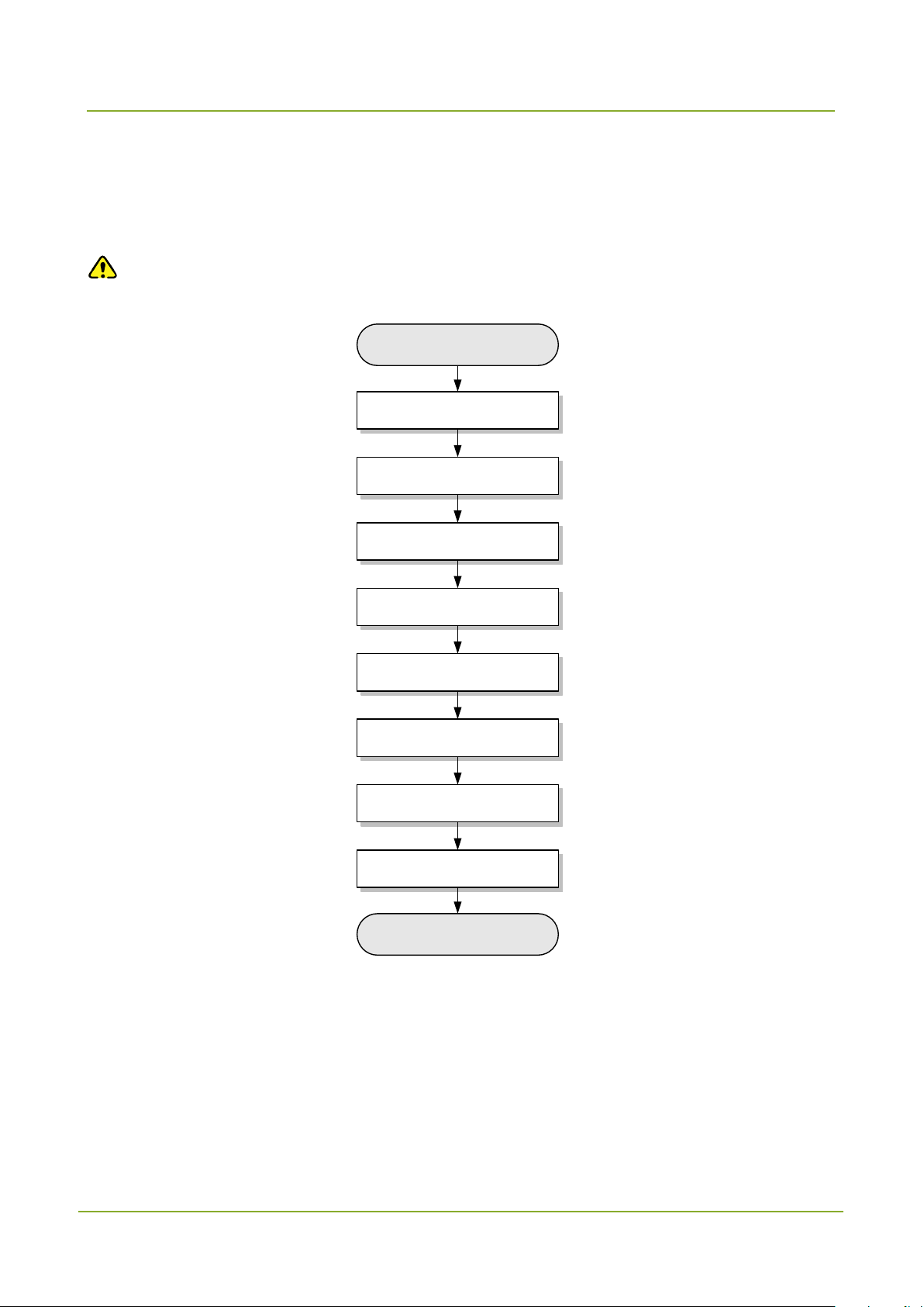
Configuration Flow
Start
Pre-configuration tasks
Program the dispatch station
Program the portable radio
Configure the SmartDispatch
Server
Configure the SmartDispatch
Gateway
Configure the SmartDispatch
Client
Commissioning
End
Program the repeater
2. Configuration Flow
The following figure describes the overall flow for configuring SmartDispatch.
Caution
Ensure you have administrative privileges before configuration.
5

Planning
SmartDispatch-Net Configuration Guide
USB
USB
SmartDispatch
Gateway 1
SmartDispatch
Server 1
SmartDispatch
Client 1
SmartDispatch
Gateway 2
SmartDispatch
Server 2
SmartDispatch
Client 2
IP Network
IP Network
Dispatch Station 2
Dispatch Station 1
Repeater 1
Repeater 2
Radio 1
Radio 2
Radio 3
IP:192.168.59.34
IP:192.168.1.35
IP:192.168.59.40
IP:192.168.1.114
IP:192.168.59.50
IP:192.168.1.51
ID:552
Subnet:24
Chanel:
MR7-VOICE:slot1
MR8-GPS:slot2
RX:449.125
TX:443.125
ID:553
Subnet:24
Chanel:
MR7-VOICE:slot1
MR8-GPS:slot2
RX:449.125
TX:443.125
ID:554
Subnet:21
Chanel:
RD9-VOICE:slot1
RD9-GPS:slot2
RX:424.89
TX:408.89
ID:1007
subnet:25
Chanel:MR8:slot2
RX:449.125
TX:443.125
ID:1007
subnet:24
Chanel:MR7:slot1
RX:449.125
TX:443.125
RX:443.125
TX:449.125
Repeater: Single Site mode
ID:91
Subnet:21
Chanel:RD9
IP:192.168.1.108
MAC:64-69-BC-04-02-79
RX:408.89
TX:424.89
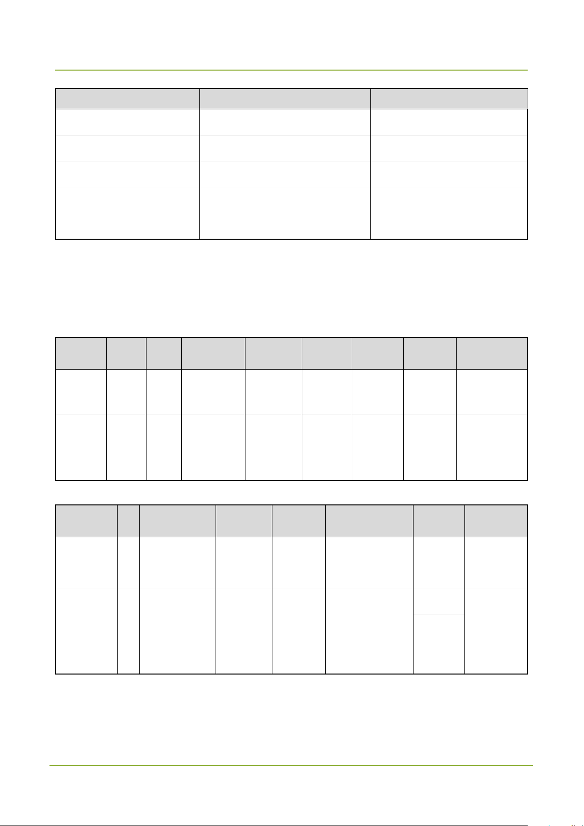
3. Planning
Caution
The data in the following figure is for your reference only.
The data configuration in this guide is based on the multi-site dispatch system.
3.1 IP Planning
Network Element IP Subnet Mask
SmartDispatch Client 1 192.168.59.34 255.255.255.0
SmartDispatch Client 2 192.168.1.35 255.255.255.0
SmartDispatch Server 1 192.168.59.40 255.255.255.0
6
SmartDispatch-Net Configuration Guide
Planning
Network Element IP Subnet Mask
SmartDispatch Server 2 192.168.1.114 255.255.255.0
SmartDispatch Gateway 1 192.168.59.50 255.255.255.0
SmartDispatch Gateway 2 192.168.1.51 255.255.255.0
Repeater 1 / /
Repeater 2 192.168.1.108 /
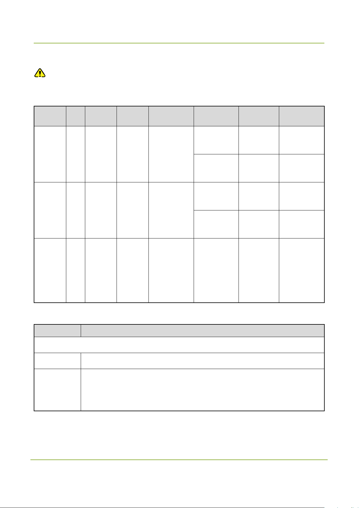
3.2 Radio Planning
Please refer to the following information when programming the dispatch station, repeater and the
portable radio.
Dispatch station
Network
Element
Dispatch
Station 1
Dispatch
Station 2
ID Alias RX Freq. TX Freq.
1007 MR7 449.125 443.125 24 MR7 Slot 1
1007 MR8 449.125 443.125 25 MR8 Slot 2
Subnet
No.
Channel Slot Function
Repeater
Network
Element
Repeater 1 / / 443.125 449.125
Repeater 2 91 Repeater3 408.89 424.89 RD9
ID Alias RX Freq. TX Freq. Channel
MR7-VOICE Slot1
MR8-GPS Slot2
Slot
Slot1
Slot2
For audio
transmission.
For GPS
data
transmission.
Function
For data
repeating.
For
working in
the Single
Site mode.
7
Planning
SmartDispatch-Net Configuration Guide
Both the SmartDispatch Client and SmartDispatch Gateway access the
Portable radio
Caution
In IP Multi-site Connect mode, be sure to enter the ID of the master repeater in the “RRS & GPS
radio ID” field when programming the portable radio.
Network
Element
Portable
radio 1
Portable
radio 2
Portable
radio 3
ID
552 449.125 443.125 1007
553 449.125 443.125 1008
554 424.89 408.89 91 MR9 Slot 1
RX
Freq.
TX Freq.
RRS & GPS
Radio ID
Channel Slot Function
MR7-VOICE Slot 1
MR8-GPS Slot 2
MR7-VOICE Slot 1
MR8-GPS Slot 2
For audio
transmission.
For GPS data
transmission.
For audio
transmission.
For GPS data
transmission.
For audio and
GPS data
transmission
through the
3.3 Port Planning
Port Description
SmartDispatch Server and SmartDispatch Gate way
1433 Indicates the database port.
61400
SmartDispatch Server via this port.
For details, see Section 8.1 Basic Settings and 9.1 Basic Settings.
8
repeater.

SmartDispatch-Net Configuration Guide
Planning
Indicates the VOIP start port of the SmartDispatch Gateway for audio
the reserved ports is twice that of the dispatch stations. For example, if the
S data
Port Description
Indicates the VOIP start port of the SmartDispatch Server for audio communication.
Up to 400 ports are reserved for audio communication. For example, if the start port
17000
number is 17000, the port range will be 17000–17399.
For details, see Section 8.1 Basic Settings.
communication. The system will reserve sufficient ports for audio communication.
When the SmartDispatch Gateway is connected to dispatch stations, the number of
19000
5060
Dispatch Station
3002
3003
SmartDispatch Gateway connects three dispatch stations and the start port number
is 19000, the reserved port numbers will be 19000 – 19005. However. If the
SmartDispatch Gateway connects to the repeater, the number of the reserved ports
is fourfold that of the repeaters.
For details, see Section 9.1 Basic Settings.
Indicates the local port of the SmartDispatch Server for telephone access.
For details, see Section 8.4 SIP Settings.
Indicates the Radio Registration Service (RRS) port number.
Do keep this value when programming the dispatch station.
Indicates the number of the Global Position System (GPS) port for GP
exchanging between radios in the IP Multi-site Connect network.
Do keep this value when programming the dispatch station.
Indicates the message port in the IP Multi-site network for the radios to send and
3004
3005
receive short messages.
Do keep this value when programming the dispatch station.
Indicates the call control port in the IP Multi-site network. If the portable radio and the
dispatch station need to realize the same function, their port numbers must be
consistent. Otherwise, they must be different.
Do keep this value when programming the dispatch station.
9

Planning
SmartDispatch-Net Configuration Guide
Port Description
Repeater
30001 Slot 1 RRS Port
30002 Slot 2 RRS Port
30003 Slot 1 LP Port
30004 Slot 2 LP Port
30005 Slot 1 TP Port
30006 Slot 2 TP Port
30007 Slot 1 TM Port
30008 Slot 2 TM Port
30009 Slot 1 RCP Port
30010 Slot 2 RCP Port
30012 Slot 1 RTP Port
30014 Slot 2 RTP Port
30015 Analog Channel RCP Port
30016 Analog Channel RTP Port
10

SmartDispatch-Net Configuration Guide
Pre-configuration Tasks
4. Pre-configuration Tasks
It is required to check the database and hardware components first before configuration.
4.1 Checking the IP Address
To check whether the IP address assigned to the dispatch station is available, open the command
window and run the “PING” command.
4.2 Checking the Port
To check the port utilization, open the command window and run the netstat –ano | findstr <port >
command. If the port is occupied, it is required to change the default port via the configuration tool.
If the port is occupied, relevant records will appear as shown in the following figure.
If the port is available, there is no record as shown in the following figure.
Note
To open a command window, go to “Start -> Run”, and type “cmd” into the text box, finally press
Enter.
4.3 Checking the Dispatch Station, Repeater and Portable
Radio
Check whether the dispatch station and portable radio have sufficient battery strength, and whether the
firmware version of the dispatch station, repeater and portable radio meets the following requirements.
Dispatch station: V4.05.16.102 or later.
Repeater: V5.06.01.006 or later.
Portable radio: V4.05.16.002 or later.
11

Pre-configuration Tasks
SmartDispatch-Net Configuration Guide
4.4 Testing the Sound Card
Test the sound card in the computer on which you want to install the SmartDispatch Gateway and
SmartDispatch Client.
Caution
Be sure to connect the microphone and speaker to the computer properly before test.
4.4.1 Testing the Sound Card in Windows XP
Step 1 Go to “Start -> Control Panel -> Sound and Audio Device -> Voice”.
Step 2 Select the default device from the drop-down list under the “Voice playback” and “Voice
recording”, and then click “Test hardware…”
Step 3 Click “Next”.
12

SmartDispatch-Net Configuration Guide
Pre-configuration Tasks
The system starts testing the sound hardware.
The following interface will appear after the test is finished.
13

Pre-configuration Tasks
SmartDispatch-Net Configuration Guide
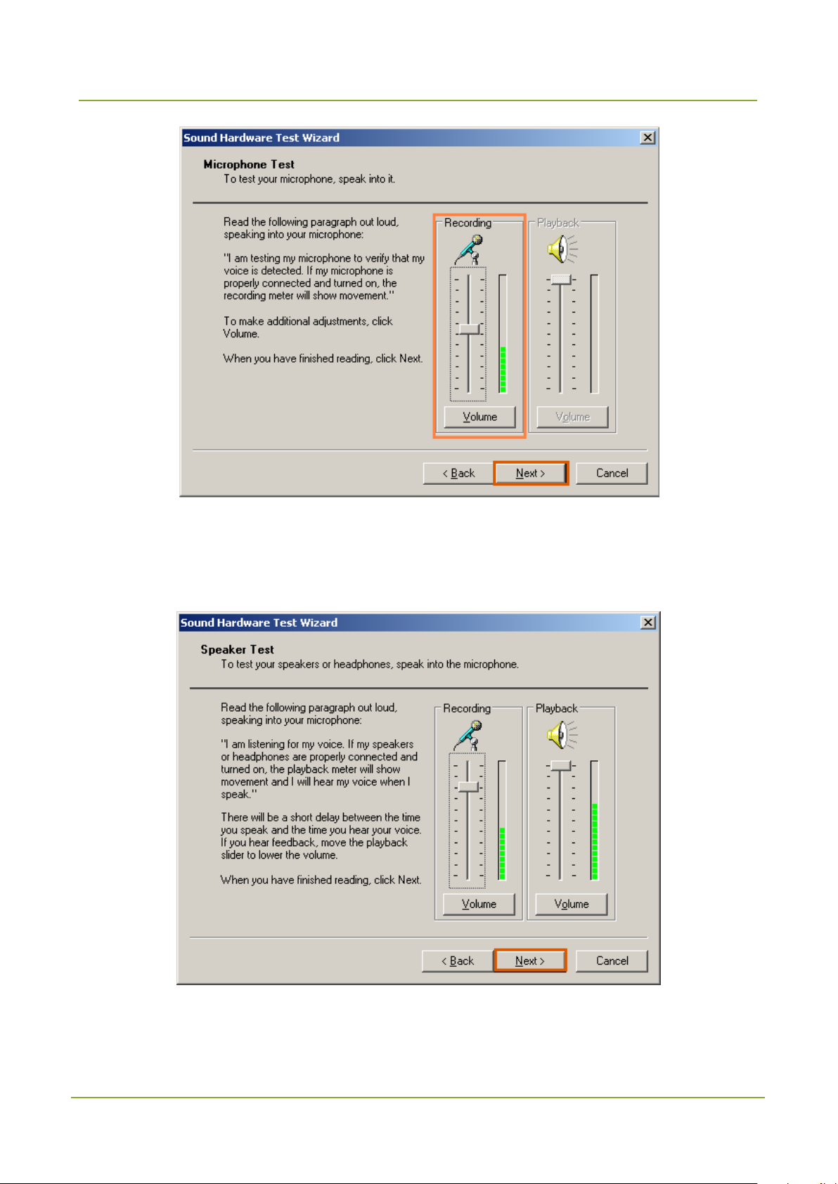
Step 4 Check the microphone. Speak into the microphone and observe whether the “Recording” meter
will show movement.
If yes, it indicates that the microphone works properly. Otherwise, you need to replace the
microphone.
14
SmartDispatch-Net Configuration Guide
Pre-configuration Tasks
Step 5 Click “Next”.
Step 6 Check the speaker. Speak into the microphone. If the speaker works properly, the “Playback”
meter will show movement.
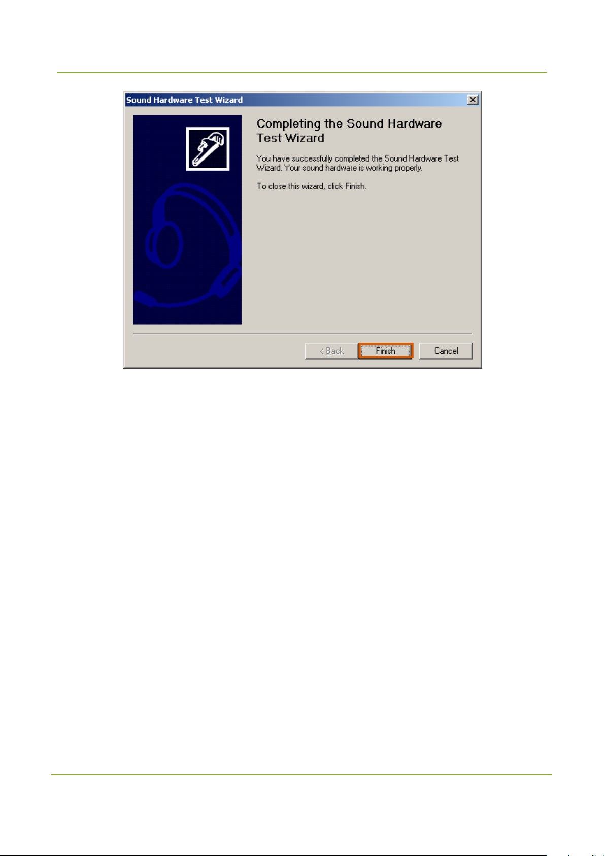
Step 7 Click “Next” and the test result appears. Then click “Finish” to complete the sound card test.
15
Pre-configuration Tasks
SmartDispatch-Net Configuration Guide
4.4.2 Testing the Sound Card in Windows 7
Be sure to connect the microphone and speaker to the computer properly before test. In Windows 7, you
should test the microphone and speaker respectively.
Testing the microphone
Step 1 Right-click the sound icon on the taskbar and select “Sounds”.
Step 2 Select the “Recording” tab in the “Sound” window.
Step 3 Select “Microphone” and click “Configure”.
16

SmartDispatch-Net Configuration Guide
Pre-configuration Tasks
Step 4 Click “Set up Microphone”.
Step 5 Select the microphone type (e.g. Desktop Microphone) and click “Next”.
17

Pre-configuration Tasks
SmartDispatch-Net Configuration Guide
Step 6 Click “Next”.
18

SmartDispatch-Net Configuration Guide
Pre-configuration Tasks
Step 7 Speak into the microphone. If the microphone works properly, the progress bar will change
accordingly. Then click “Next”.
If the microphone does not work properly, please update the driver program or replace your
microphone, and then test it again.
The bar in the red circle will change
according to the varying sound volume.
Step 8 Click “Finish”.
19

Pre-configuration Tasks
SmartDispatch-Net Configuration Guide
Testing the speaker
Step 1 Select the “Playback” tab in the “Sound” window.
Step 2 Right-click “Speakers” and select “Test”.
If you can hear the sound, it indicates the speaker is ready for use.
20

SmartDispatch-Net Configuration Guide
Pre-configuration Tasks
Testing the recording
Step 1 Select the “Recording” tab in the “Sound” window.
Step 2 Right-click “Microphone” and select “Properties”.
21

Pre-configuration Tasks
SmartDispatch-Net Configuration Guide
Step 3 Select the “Listen” tab and select “Listen to this device”, and then select the device from the
drop-down list under “Playback through this device”.
Caution
This step is intended to test the recording only. In general, do not select the option “Listen to
this device”.
Step 4 Speak into the microphone.
If the microphone works properly, you will hear the sound and the volume indicator changes
accordingly.
Step 5 Click “OK” to finish.
22
SmartDispatch-Net Configuration Guide
Pre-configuration Tasks
4.5 Configuring the Multi-channel Sound Card
4.5.1
Step 1 Insert the multi-channel sound card into the PCI slot of the computer.
Step 2 Install the driver program.
Installing the Multi-channel Sound Card
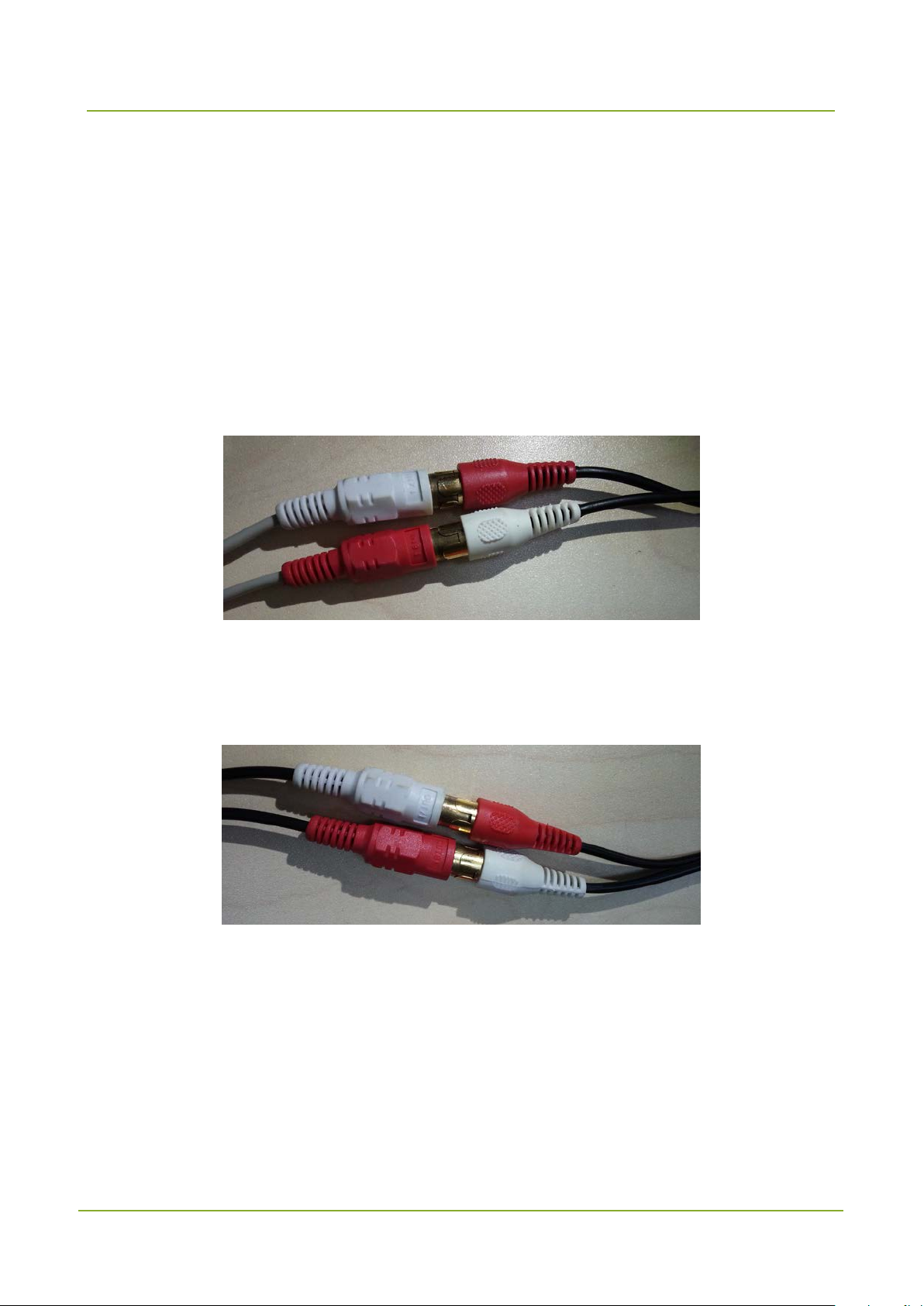
4.5.2 Connecting the Cable
You can see the “In” or “Out” label on the connectors of the cable. Make sure that the connectors labeled
“In” are connected to the microphone and those labeled “Out” are connected to the earpiece or speaker.
Step 1 Insert the connectors labeled “IN7↓”and “IN8↓”into the matching jacks on the breakout cable.
Step 2 Plug the other end of the breakout cable into the microphone jack of the dispatch station.
Step 3 Insert the connectors labeled “OUT7↑”and “OUT8↑”into the matching jacks on the breakout
cable.
Step 4 Plug the other end of the breakout cable into the speaker jack of the dispatch station. See the
connection as follows.
23

Pre-configuration Tasks
SmartDispatch-Net Configuration Guide
4.6 Instructions
Deactivating the microphone boost feature
You need to deactivate the microphone boost feature in Windows XP. To do this, follow the steps below:
Step 1 Go to “Start -> Control Panel -> Sound and Audio Device -> Voice”.
Step 2 Click the “Volume” tab and click “Advanced” in the “Device volume” box.
24

SmartDispatch-Net Configuration Guide
Pre-configuration Tasks
Step 3 Open the “Recording Control” panel and click “Advanced”.
Note
It is required to open the “Recording Control” panel first.
Step 4 Clear the check box labeled “1 Microphone Boot” and click “Close”.
Deactivating the listening feature
You need to deactivate the listening feature in Windows 7. To do this, follow the steps below:
Step 1 Right-click the sound icon on the taskbar and select “Sounds”.
25

Pre-configuration Tasks
SmartDispatch-Net Configuration Guide
Step 2 Select the “Recording” tab in the “Sound” window.
Step 3 Select “Microphone” and click “Prosperities”.
Step 4 Clear the check box labeled “Listen to this device” and click “OK”.
26

SmartDispatch-Net Configuration Guide
Programming the Dispatch Station
5. Programming the Dispatch Station
Caution
Read the data from the dispatch station and the portable radio before programming.
It is recommended to deploy two dispatch stations in a group to transmit the audio signals and
GPS data separately, so that the GPS data reception will not be affected. In this case, these
dispatch stations must share the same ID.
The firmware version of the dispatch stations must be V4.05.16.102 or later.
5.1 Basic Settings
Step 1 Open the Customer Programming Software.
Step 2 Click the icon in the toolbar to read the data from the dispatch station.
Step 3 Click to enter the following window.
27

Programming the Dispatch Station
SmartDispatch-Net Configuration Guide
The fourth section must be s et to 1. It is highly
Step 4 Click to start reading the data from the dispatch station. After the data is read
successfully, click
Step 5 Go to “Conventional -> General Setting -> Network” in the left navigation tree.
Step 6 Set the following parameters.
in the following window.
Do follow the settings specified in the table below.
Parameter Settings
Radio Control Station IP
recommended to set this IP to “192.168.Subnet.1”.
Forward To PC Be sure to select this option.
28

SmartDispatch-Net Configuration Guide
Programming the Dispatch Station
This parameter defines the first field of IP address in the
Parameter Settings
virtual subnet.
The range is 1–126.
Caution
The subnet must be different from the first section of
the IP address for accessing the SmartDispatch
Subnet
Gateway. For example, if the IP address of the
SmartDispatch Gateway is 10.168.24.43, the subnet
must not be set to 10. Otherwise, it may cause
communication failure.
In the same group, it is better to set the subnet of the
dispatch station (for audio transmission) and the
dispatch station (for GPS data transmission) to be
different.
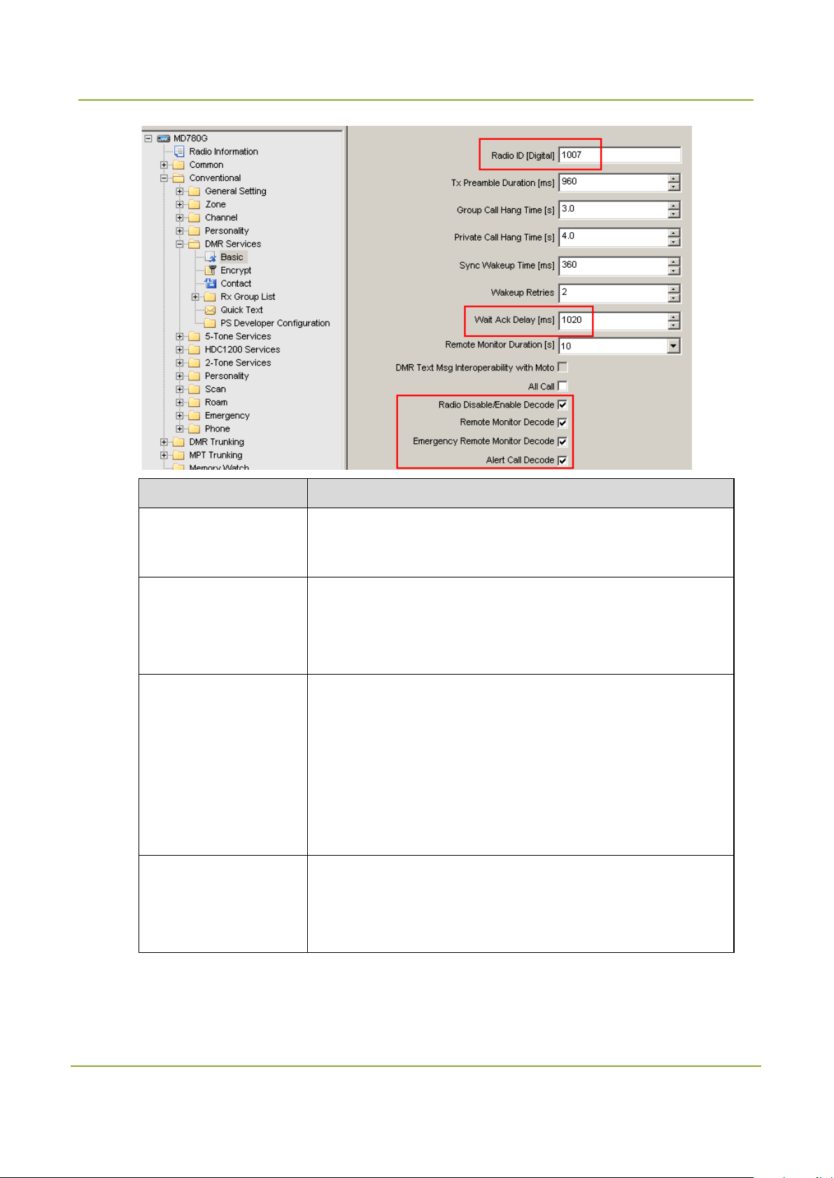
5.2 DMR Service Settings
Step 1 Go to “Conventional -> DMR Services -> Basic”.
Step 2 Set the following parameters.
Do follow the settings specified in the table below.
29
Programming the Dispatch Station
SmartDispatch-Net Configuration Guide
Sets whether the dispatch station can decode the Radio
programming or
Sets whether the dispatch station can decode the Remote
Parameter Settings
Radio ID [Digital]
Wait Ack Delay [ms]
Radio
Disable/Enable Decode
Remote
Monitor Decode
Sets the identity of the dispatch station. It must be unique.
The range is 1–16776415.
Sets the time period of waiting for an ACK after sending data or
command.
The value must be greater than 990.
Disable/Enable command. The disabled dispatch station will be
incapable of any operation, but can be monitored remotely. In
this case, it can only be enabled through re-
decoding the Radio Enable command.
Be sure to select this option.
Monitor command.
Be sure to select this option.
30

SmartDispatch-Net Configuration Guide
Programming the Dispatch Station
ets whether the dispatch station can decode the Alert Call
Parameter Settings
S
Alert Call Decode
command.
Be sure to select this option.
5.3 Channel Settings
In any case, you must select the following options: “Emergency Alarm Indication”, “Emergency Alarm
Ack” and “Emergency Call Indication”.
Caution
It is recommended to use different channels for GPS data and audio transmission.
One dispatch station in a group
In this case, only one dispatch station is employed to transmit both the audio signals and GPS data in a
group.
Step 1 Go to “Conventional -> Channel -> Digital Channel”.
Step 2 Set the following parameters.
Caution
You must select the following options: “Emergency Alarm Indication”, “Emergency Alarm Ack” and
“Emergency Call Indication”.
31

Programming the Dispatch Station
SmartDispatch-Net Configuration Guide
Two dispatch stations in a group
In this case, two dispatch stations are employed in a group to transmit the audio signals and GPS data
separately. If these dispatch stations work at the same frequency, they must use different slots.
Step 1 Go to “Conventional -> Channel -> Digital Channel”.
Step 2 Set the following parameters. Please note that the settings of the two dispatch stations will be
different.
Caution
You must select the following options: “Emergency Alarm Indication”, “Emergency Alarm Ack” and
“Emergency Call Indication”.
32

SmartDispatch-Net Configuration Guide
Programming the Dispatch Station
Pseudo Trunking
If you need to use the Pseudo Trunking feature, the portable radio should enable the Pseudo Trunking
feature and the dispatch station should meet the following requirements simultaneously:
Two dispatch stations are required in the same group.
The Pseudo Trunking feature is disabled in the dispatch station.
Two dispatch stations must operate on different slot.
33

Programming the Repeater
SmartDispatch-Net Configuration Guide
6. Programming the Repeater
Caution
The version of the repeater must be V5.06.01.006 or later.
6.1 Single Site Mode
General Setting
In the Single Site mode, the repeater only works in the local mode. It is required to connect the repeater
to the SmartDispatch Gateway.
Step 1 Open the Customer Programming Software and read the configuration from the repeater.
Step 2 Go to “Conventional -> General Setting -> Accessories” in the left navigation tree.
Step 3 Set the “Path Priority” to “PTT Request”. When both the repeat request and PTT request come
simultaneously, the repeater will first respond to the PTT request.
Step 4 Go to “Conventional -> General Setting -> Network” in the left navigation tree, and set the
following parameters.
34

SmartDispatch-Net Configuration Guide
Programming the Repeater
Parameter Description
Basic Setting
Ethernet IP Sets the IP address of the repeater.
Sets the address of the repeater in the network. It must be
MAC Address
IP Multi-site Connect
Repeater Type
Application Programming Interface
unique.
Make sure that each value in the each part is different.
If you select “Single Site” from the drop-down list, the repeater
will work in the local mode rather than the IP Multi-site
Connect mode.
In the network, the repeater can forward the received data via
Forward To PC
the Ethernet to the computer, and receive and respond to the
repeat request from the computer, to realize communication
35

Programming the Repeater
SmartDispatch-Net Configuration Guide
Parameter Description
between SmartDispatch and the radios.
Third Party Server IP Sets the IP address of the SmartDispatch Gateway.
Channel
Step 1 Go to “Conventional -> Channel -> Digital Channel” in the left navigation tree.
Step 2 Set the channel alias, RX frequency and TX frequency.
DMR Services
Step 1 Go to “Conventional -> DMR Services -> Basic”.
Step 2 Set the radio ID.
6.2 IP Multi-site Connect Mode
6.2.1
In the IP Multi-site Connect mode, multiple repeaters in dispersed locations can be connected to
Introduction
36

SmartDispatch-Net Configuration Guide
Programming the Repeater
Connecting two or more repeaters in
The local repeater can connect to other repeaters in
rain, to achieve
alize more
exchange the audio signals and data over a TCP/IP-based network. In this way, the data will be
transmitted over IP Multi-site Connect network, extending the repeater’s coverage. The repeater can
work in the IP Multi-site Connect mode only when you purchase the IP Multi-site Connect feature and
enable it in advance.
Each IP Multi-site Connect network supports up to fifteen IP sites, including one master site and fourteen
slave sites. The slave sites are managed and controlled by the master site. You must configure the
Master repeater and Slave repeater respectively. The Master repeater with the static IP address is used
to record the location of the Slave repeater in the network for forwarding the data.
The IP Multi-site Connect feature can bring you these typical benefits:
Benefit Example
dispersed locations
Extending the communication coverage
Broadcasting messages to all connected
repeaters
Connecting repeaters working in varied
frequency bands
Connecting IP-based applications
6.2.2 Normal Mode
dispersed locations over the IP Multi-site Connect network.
Multiple repeaters can be deployed in a large building to
overcome obstacles like unfavorable ter
seamless communications.
In case of an emergency, the dispatch station can send an
instruction to all repeaters in IP Multi-site Connection
mode.
The UHF repeaters and VHF repeaters can be connected
so that data and voice can be exchanged among them.
In the IP Multi-site Connect mode, you can use IP-based
software developed by any third party to re
functions.
In the Normal mode, once any repeater receives the data or command, it will transfer such data or
command to other repeaters over the IP Multi-site Connect network. It is only required to connect the
master repeater to the SmartDispatch Gateway.
The system architecture is illustrated as below.
37

Programming the Repeater
SmartDispatch-Net Configuration Guide
SmartDispatch
Gateway
Radio1
Radio2
IP
SmartDispatch
Server
SmartDispatch
Client
Master Repeater
Slave Repeater
Slave Repeater
Radio Network
Master Repeater
General Setting
Step 1 Open the Customer Programming Software and read the configuration from the repeater.
Step 2 Go to “Conventional -> General Setting -> Accessories” in the left navigation tree.
Step 3 Set the “Path Priority” to “PTT Request”. When both the repeat request and PTT request come
simultaneously, the repeater will first respond to the PTT request.
38

SmartDispatch-Net Configuration Guide
Programming the Repeater
Step 4 Go to “Conventional -> General Setting -> Network” in the left navigation tree, and set the
parameters in the “Basic Setting” box.
Parameter Description
DHCP Do not select this option.
It must be unique. Otherwise, communication may be failure in the
Ethernet IP
system.
It must be unique.
Gateway IP
Please note that the last digit should not be set to “0”.
Netmask 255.255.255.0
39
Programming the Repeater
SmartDispatch-Net Configuration Guide
site Connect
defines the length of buffer area for the
repeater to process the received voice and dat a in the IP
to improve the
Parameter Description
Sets the address of the repeater in the network. It must be unique.
MAC Address
Make sure that each value in the each part is different.
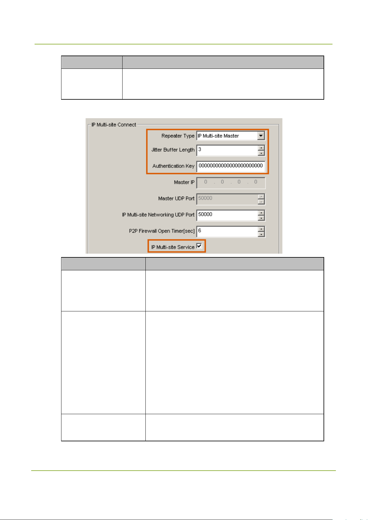
Step 5 Set the parameters in the “IP Multi-site Connect” box.
Parameter Description
When this option is set to “IP Multi-site Master”, the repeater
Repeater Type
will act as the master one in the IP Multi-
network.
This parameter
network. You should set this parameter based on the actual
network conditions. For example, if there is a poor network
Jitter Buffer Length
connection, the value should be greater
communication continuity. In the IP M ulti-site Connect
network, it is recommended to set this parameter to 3. The
range is 1 - 8.
Authentication Key
Sets the password for accessing the IP Multi-site Connect
network. Please note that the authentication key of the slave
40
SmartDispatch-Net Configuration Guide
Programming the Repeater
If you leave this parameter blank, it indicates that no
Parameter Description
repeater must be identical with that of the master repeater in
the same IP Multi-site Connect network.
authentication is required.
This key can contain up to 40 characters (0–9 and A–F).
IP Multi-site Service Be sure to select this option.
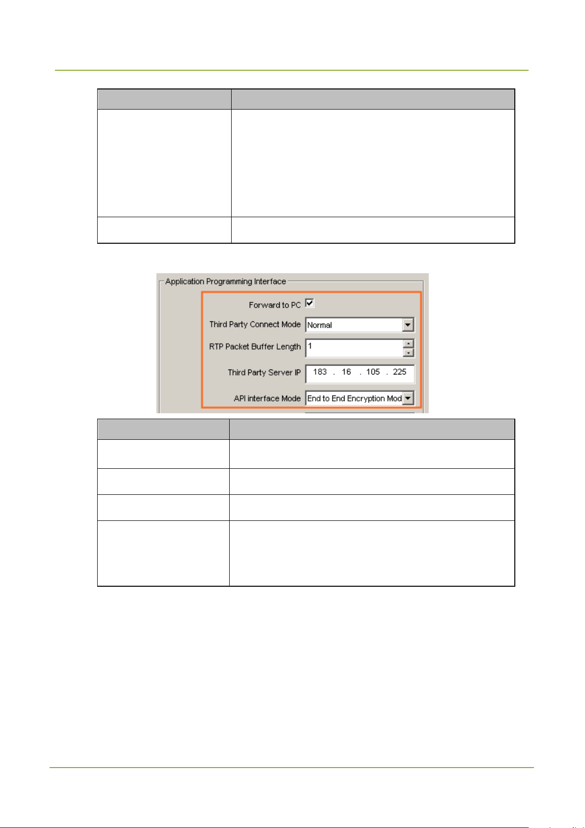
Step 6 Set the parameters in the “Application Programming Interface” box.
Parameter Description
Forward To PC Be sure to select this option.
Third Party Connect Mode Be sure to select “Normal” from the drop-down list.
Third Party Server IP Sets the IP address of the SmartDispatch Gateway.
Be sure to select “End to End Encryption Mode” if you need
API interface Mode
to use the Voice Encryption feature; otherwise, keep the
default settings.
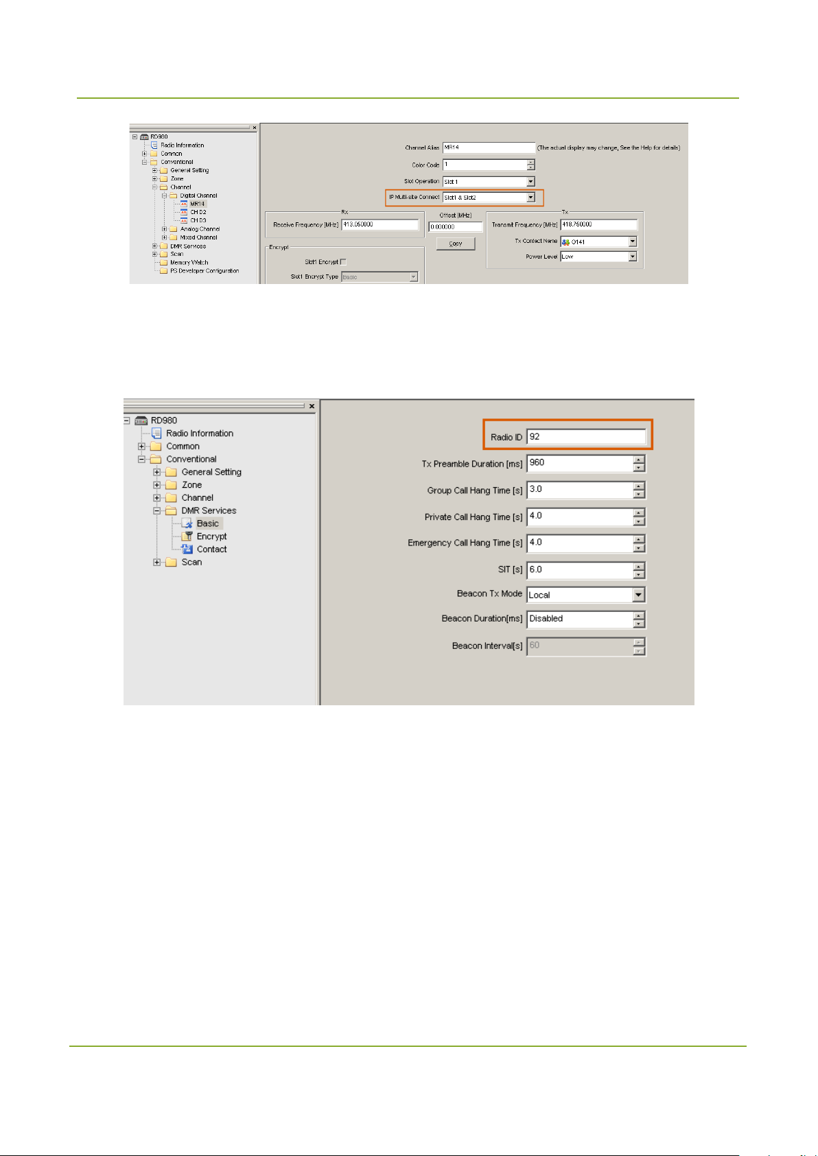
Channel
Step 1 Go to “Conventional -> Channel -> Digital Channel” in the left navigation tree.
Step 2 Set the “IP Multi-site Connect” to “Slot 1& Slot 2”. Thus the repeater uses Slot 1 and Slot 2 to
forward the data in the IP Multi-site Connect network.
41
Programming the Repeater
SmartDispatch-Net Configuration Guide
DMR Services
Step 1 Go to “Conventional -> DMR Services -> Basic”.
Step 2 Set the radio ID.
Slave Repeater
General Setting
Step 1 Open the Customer Programming Software and read the configuration from the repeater.
Step 2 Go to “Conventional -> General Setting -> Accessories” in the left navigation tree.
Step 3 Set the “Path Priority” to “PTT Request”. When both the repeat request and PTT request come
simultaneously, the repeater will first respond to the PTT request.
42

SmartDispatch-Net Configuration Guide
Programming the Repeater
Sets the address of the repeater in the network. It must be
Step 4 Go to “Conventional -> General Setting -> Network” in the left navigation tree,
Step 5 Set the parameters in the “Basic Setting” box.
Parameter Description
DHCP Be sure to select this option.
MAC Address
unique.
Make sure that each value in the each part is different.
Step 6 Set the parameters in the “IP Multi-site Connect” box.
43

Programming the Repeater
SmartDispatch-Net Configuration Guide
This parameter defines the length of buffer area for the
repeater to process the received voice and dat a in the IP
to improve the
, it indicates that no
Sets the IP address of the master repeater in the IP
Parameter Description
Repeater Type
Jitter Buffer Length
Authentication Key
When this option to “IP Multi-site Slave”, the repeater will act
as the slave one in the IP Multi-site Connect network.
network. You should set this parameter based on the actual
network conditions. For example, if there is a poor network
connection, the value should be greater
communication continuity. In the IP Multi-site Connect, it is
recommended to set this parameter to 3. The range is 1 - 8.
Sets the password for accessing the IP Multi-site Connect
network. Please note that the authentication key of the slave
repeater must be identical with that of the master repeater in
the same IP Multi-site Connect network.
If you leave this parameter blank
authentication is required.
This key can contain up to 40 characters (0–9 and A–F).
Master IP
Multi-site Connect network.
44
SmartDispatch-Net Configuration Guide
Programming the Repeater
Parameter Description
IP Multi-site Service Be sure to select this option.
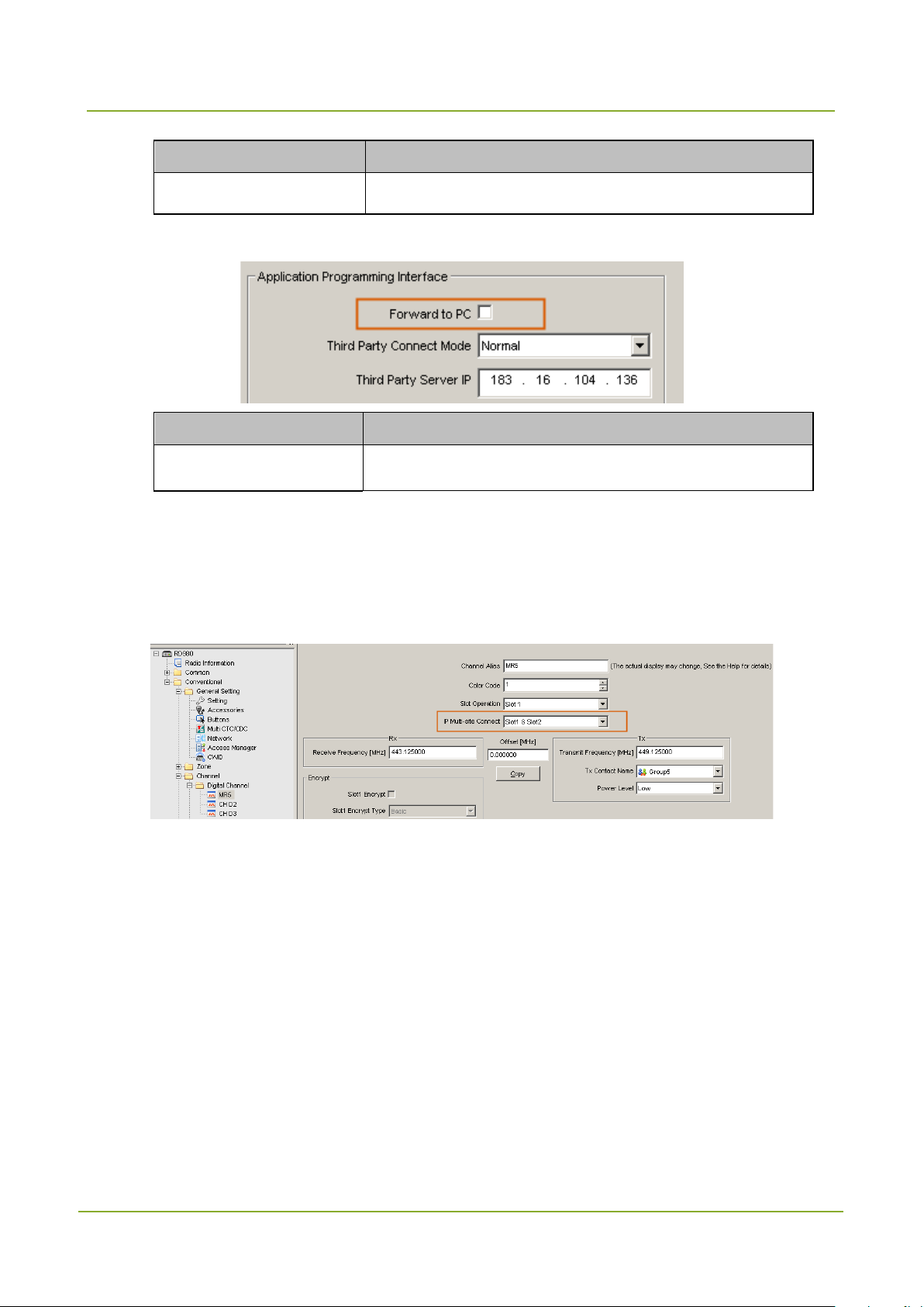
Step 7 Set parameters in the “Application Programming Interface” box.
Parameter Description
Forward To PC Do not select this option.
Channel
Step 1 Go to “Conventional -> Channel -> Digital Channel” in the left navigation tree.
Step 2 Set the “IP Multi-site Connect” to “Slot 1& Slot 2”. Thus the repeater uses Slot 1 and Slot 2 to
forward the data in the IP Multi-site Connect network.
DMR Services
Step 1 Go to “Conventional -> DMR Services -> Basic”.
Step 2 Set the radio ID.
45

Programming the Repeater
SmartDispatch-Net Configuration Guide
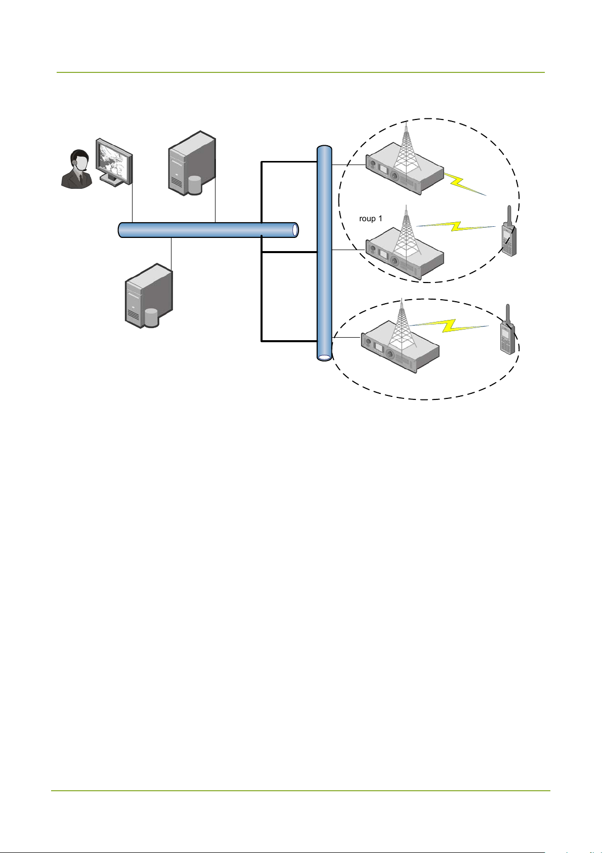
6.2.3 Selective Mode
In the selective mode, the repeater activates the Access Manager feature, to repeat the right data to the
right radio over the IP network. Thus point-to-point communications can be achieved between repeaters
with the same Access Manager feature.
Each repeater connects to the SmartDispatch Gateway and transmits the received data from the air
interface to it, while the SmartDispatch sends the data and command to each repeater respectively.
The system architecture is illustrated as below.
46
SmartDispatch-Net Configuration Guide
Programming the Repeater
Group 1
SmartDispatch
Gateway
Radio1
Radio2
IP
SmartDispatch Server
SmartDispatch
Client
Master Repeater
Slave Repeater
Slave Repeater
Group 2
Repeater IP Multi-site Connect Network
Master Repeater
General Setting
Step 1 Open the Customer Programming Software and read the configuration from the repeater.
Step 2 Go to “Conventional -> General Setting -> Accessories” in the left navigation tree.
Step 3 Set the “Path Priority” to “PTT Request”. When both the repeat request and PTT request come
simultaneously, the repeater will first respond to the PTT request.
47

Programming the Repeater
SmartDispatch-Net Configuration Guide
Step 4 Go to “Conventional -> General Setting -> Network” in the left navigation tree, and set the
parameters in the “Basic Setting” box.
Parameter Description
DHCP Do not select this option.
It must be unique. Otherwise, communications may be failure in
Ethernet IP
the system.
Gateway IP
It must be u nique. Please note that the last digit should not be
set to “0”.
48

SmartDispatch-Net Configuration Guide
Programming the Repeater
site Connect
This parameter defines the length of buffer area for the
repeater to process the received voice and dat a in the IP
to improve the
network. Please note that the authentication key of the slave
Parameter Description
Netmask 255.255.255.0
Sets the address of the repeater in the network. It must be
MAC Address
unique.
Make sure that each value in the each part is different.
Step 5 Set the parameters in the “IP Multi-site Connect” box.
Parameter Description
Sets this option to “IP Multi-site Master”. Then the repeater
Repeater Type
will act as the master one in the IP Multi-
network.
network. You should set this parameter based on the actual
Jitter Buffer Length
network conditions. For example, if there is a poor network
connection, the value should be greater
communication continuity. In the IP Multi-site Connect, it is
recommended to set this parameter to 3. The range is 1 - 8.
Sets the password for accessing the IP Multi-site Connect
Authentication Key
49

Programming the Repeater
SmartDispatch-Net Configuration Guide
that no
keep the
Parameter Description
repeater must be identical with that of the master repeater in
the same IP Multi-site Connect network.
If you leave this parameter blank, it indicates
authentication is required.
This key can contain up to 40 characters (0–9 and A–F).
IP Multi-site Service Be sure to select this option.
Step 6 Set parameters in the “Application Programming Interface” box.
Parameter Description
Forward To PC Be sure to select this option.
Third Party Connect Mode Be sure to select “Selective” from the drop-down list.
Third Party Server IP Sets the IP address of the SmartDispatch Gateway.
Be sure to select “End to End Encryption Mode” if you need
API interface Mode
to use the Voice Encryption feature; otherwise,
default settings.
Channel
Step 1 Go to “Conventional -> Channel -> Digital Channel” in the left navigation tree.
Step 2 Set the “IP Multi-site Connect” to “Slot 1& Slot 2”. Thus the repeater uses Slot 1 and Slot 2 to
forward the data in the IP Multi-site Connect network.
50

SmartDispatch-Net Configuration Guide
Programming the Repeater
DMR Services
Step 1 Go to “Conventional -> DMR Services -> Basic”.
Step 2 Set the radio ID.
Slave Repeater
Basic Setting
Step 1 Open the Customer Programming Software and read the configuration from the repeater.
Step 2 Go to “Conventional -> General Setting -> Accessories” in the left navigation tree.
Step 3 Set the “Path Priority” to “PTT Request”. When both the repeat request and PTT request come
simultaneously, the repeater will first respond to the PTT request.
51

Programming the Repeater
SmartDispatch-Net Configuration Guide
er in the network. It must be
Step 4 Go to “Conventional -> General Setting -> Network” in the left navigation tree.
Step 5 Set the parameters in the “Basic Setting” box.
Parameter Description
DHCP Be sure to select this option.
Sets the address of the repeat
MAC Address
unique.
Make sure that each value in the each part is different.
Step 6 Set the parameters in the “IP Multi-site Connect” box.
52

SmartDispatch-Net Configuration Guide
Programming the Repeater
site Connect
This parameter defines the length of buffer area for the
repeater to process the received voice and dat a in the IP
to improve the
ameter blank, it indicates that no
Sets the IP address of the master repeater in the IP
Parameter Description
Sets this option to “IP Multi-site Slave”. Then the repeater
Repeater Type
Jitter Buffer Length
Authentication Key
will act as the slave one in the IP Multi-
network.
network. You should set this parameter based on the actual
network conditions. For example, if there is a poor network
connection, the value should be greater
communication continuity. In the IP Multi-site Connect, it is
recommended to set this parameter to 3. The range is 1 - 8.
Sets the password for accessing the IP Multi-site Connect
network. Please note that the authentication key of the slave
repeater must be identical with that of the master repeater in
the same IP Multi-site Connect network.
If you leave this par
authentication is required.
This key can contain up to 40 characters (0–9 and A–F).
Master IP
Multi-site Connect network.
53

Programming the Repeater
SmartDispatch-Net Configuration Guide
Parameter Description
IP Multi-site Service Be sure to select this option.
Step 7 Set parameters in the “Application Programming Interface” box.
Parameter Description
Forward To PC Be sure to select this option.
Third Party Connect Mode Be sure to select “Selective” from the drop-down list.
Third Party Server IP Sets the IP address of the SmartDispatch Gateway.
Channel
Step 1 Go to “Conventional -> Channel -> Digital Channel” in the left navigation tree.
Step 2 Set the “IP Multi-site Connect” to “Slot 1& Slot 2”. Thus the repeater uses Slot 1 and Slot 2 to
forward the data in the IP Multi-site Connect network.
DMR Services
Step 3 Go to “Conventional -> DMR Services -> Basic”.
Step 4 Set the radio ID. The radio ID of the slave repeater can not be identical with that of the master
repeater.
54
SmartDispatch-Net Configuration Guide
Programming the Repeater
6.3 Encryption
You should set the encrypt key for the repeater before using the Voice Encryption feature. Make sure
that this key is identical with that of the radio and SmartDispatch Client. In addition, you should configure
the appropriate parameters in the SmartDispatch Gateway (See the description of “Encrypt Slot” in “9.3
Repeater Settings”).
Caution
The “API interface Mode” parameter should be set to “End to End Encryption Mode” for the
repeater via the CPS. For more information, see the previous section “6.2 IP Multi-site Connect
Mode”.
If both the master repeater and slave repeater are available in the system, you should configure
the same encrypt key for them.
Follow the steps below to set the encrypt key:
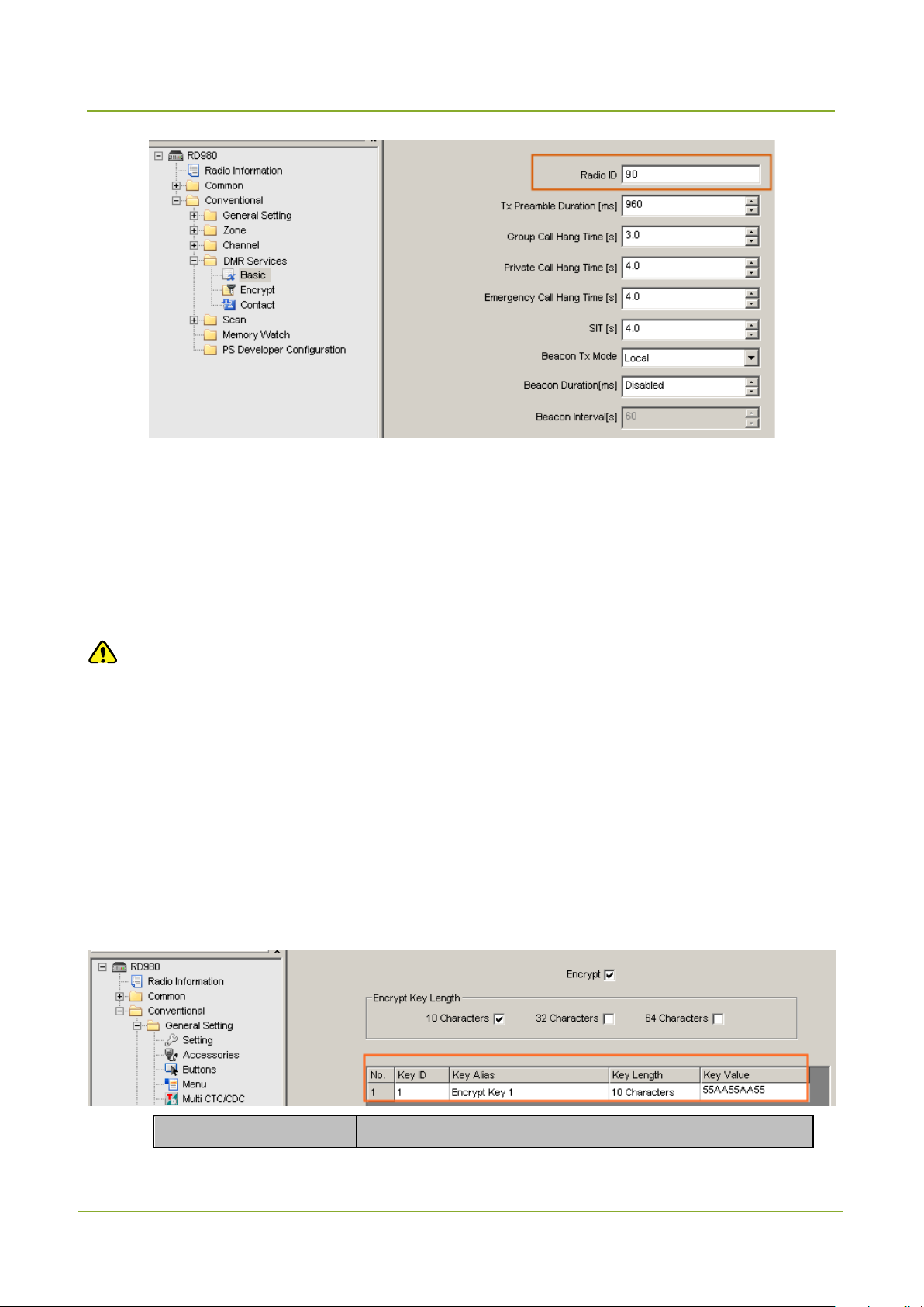
Step 1 Go to “Conventional -> DMR Services -> Encrypt”.
Step 2 Select “Encrypt” and enter an encrypt key.
Parameter Description
55
Programming the Repeater
SmartDispatch-Net Configuration Guide
the “Key
Parameter Description
Defines the length of the key you enter. Currently there are
Encrypt Key Length
three options: 10, 32 and 64 characters. As long as you set
this parameter, you can enter the encrypt key in
Length”.
Key ID The ID must be unique.
Key Alias The alias must be unique.
Be sure to enter the hexadecimal numbers. The length of key
Key Value
value is subject to the settings in the “Key Length”.
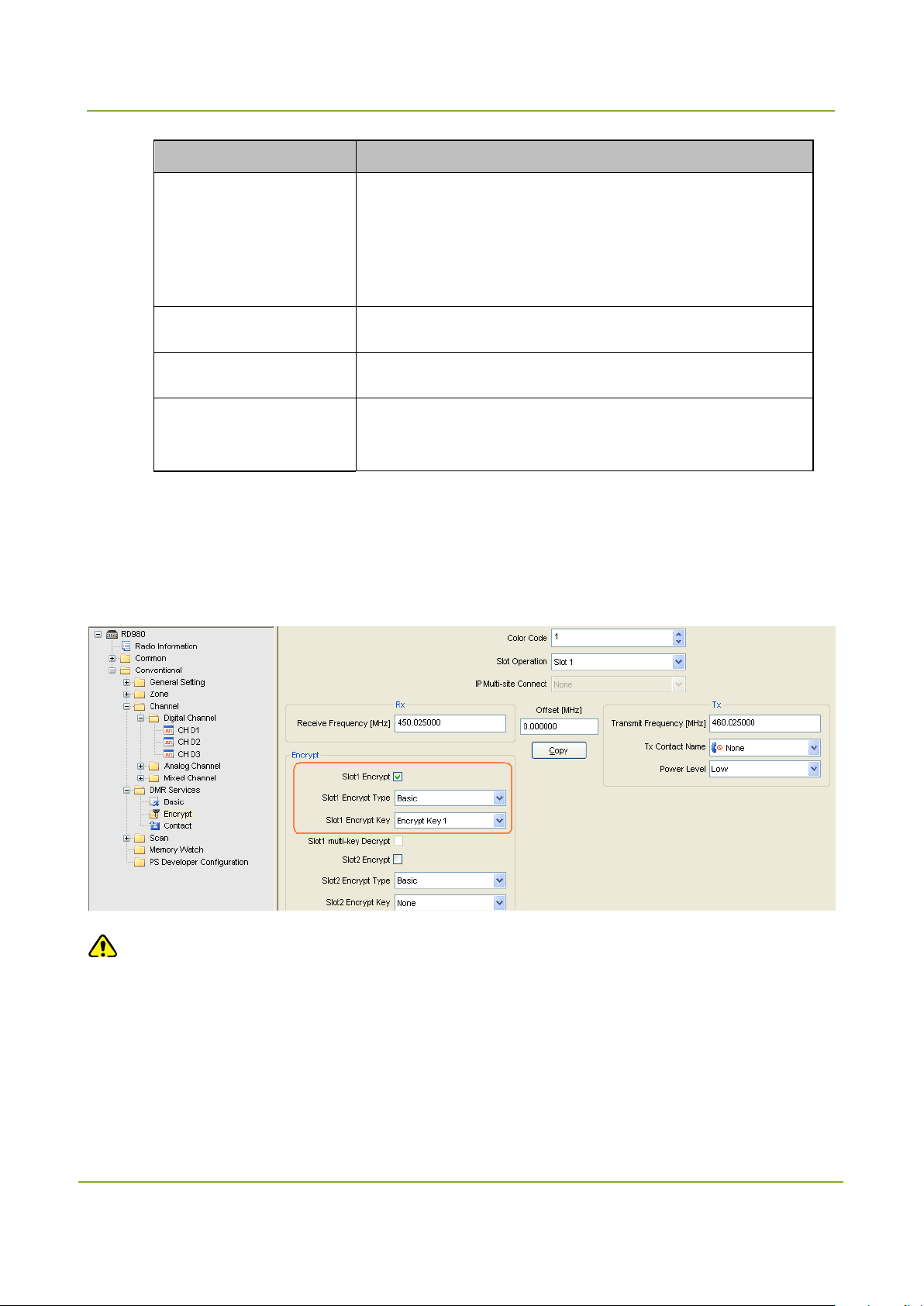
Step 3 Go to “Conventional -> Channel -> Digital Channel”.
Step 4 Set the encrypt key. For example, you use slot 1 for voice transmission. Thus, select “Slot1
Encrypt”, and choose the corresponding encrypt key for slot 1.
Caution
After setting the encrypt key for slot 1 in the CPS, you should select slot 1 for outputting the audio via the
menu in the repeater: “Main Menu -> Digital Speaker -> Slot 1”.
56

SmartDispatch-Net Configuration Guide
Programming the Portable Radio
7. Programming the Portable Radio
Caution
The Customer Programming Software (V4.05.16.002 or later) is required.
To activate the Pseudo Trunking feature, there must be two dispatch stations in the same group
but on different slots.
7.1 Basic Setting
Step 1 Open the Customer Programming Software.
Step 2 Click the icon in the toolbar to read the data from the portable radio.
Step 3 Click to enter the following window.
57

Programming the Portable Radio
SmartDispatch-Net Configuration Guide
Step 4 Click to start reading the data from the portable radio. After the data is read
successfully, click
.
The following window appears.
Step 5 Go to “Conventional -> General Setting -> Network” in the left navigation tree.
Step 6 Set the following parameters.
Do follow the settings specified in the table below.
58

SmartDispatch-Net Configuration Guide
Programming the Portable Radio
radio ID specified in the
Parameter Settings
RRS & GPS Radio ID
Be sure to enter the corresponding
dispatch station or repeater. Otherwise, the registration will fail
and the radio can not work properly.
59

Programming the Portable Radio
SmartDispatch-Net Configuration Guide
the dispatch
Do not select this option. Otherwise, the message may not be
sent successfully.
It must be c onsistent with that in the dispatch station or
Parameter Settings
Enters the dispatch station ID in this field if
station is employed in the SmartDispatch system.
If the repeater is employed in the SmartDispatch system,
do as follows:
Enters the ID of the master repeater in the Normal mode.
Enters the ID of the repeater which the radio belongs to
in the Selective mode
Forward To PC
Subnet
repeater.
RRS Delay Registration
Time
RRS Registration Retry
Counter
RRS Registration Retry
Interval
Step 7 Click “Close” to finish.
Defines the time between the power-on and registration. It is
recommended to set to 10 seconds.
Defines the maximum retry times for the portable radio to send
the registration message.
It must be set to 500 (maximum).
Defines the interval of retrying the registration. It must be set to
300 (maximum).
7.2 DMR Service Settings
Step 1 Go to “Conventional -> DMR Services -> Basic”.
60

SmartDispatch-Net Configuration Guide
Programming the Portable Radio
Radio Disable/Enable
Sets whether the portable radio can decode the Radio
Sets whether the portable radio can decode the Remote
Step 2 Set the parameters as per the table below.
Parameter Settings
Sets the identity of the portable radio. It must be unique.
Radio ID [Digital]
The range is 1~16776415.
Sets the time period of waiting for an ACK after sending data
Wait Ack Delay [ms]
or command.
The value must be greater than 990.
Disable/Enable command.
Decode
Be sure to select this option.
Remote Monitor Decode
Monitor command.
Be sure to select this option.
61
Programming the Portable Radio
SmartDispatch-Net Configuration Guide
Sets whether the portable radio can decode the Alert Call
Parameter Settings
Alert Call Decode
command.
Be sure to select this option.
7.3 Channel Settings
You can choose to deploy one dispatch station in a group to transmit both the audio signals and GPS
data, or two dispatch stations in a group to transmit the audio signals and GPS data separately. Thus,
you must configure the portable radio according to the deployment of the dispatch station.
One dispatch station in a group
If only one dispatch station is employed in a group to transmit both the audio signals and GPS data, you
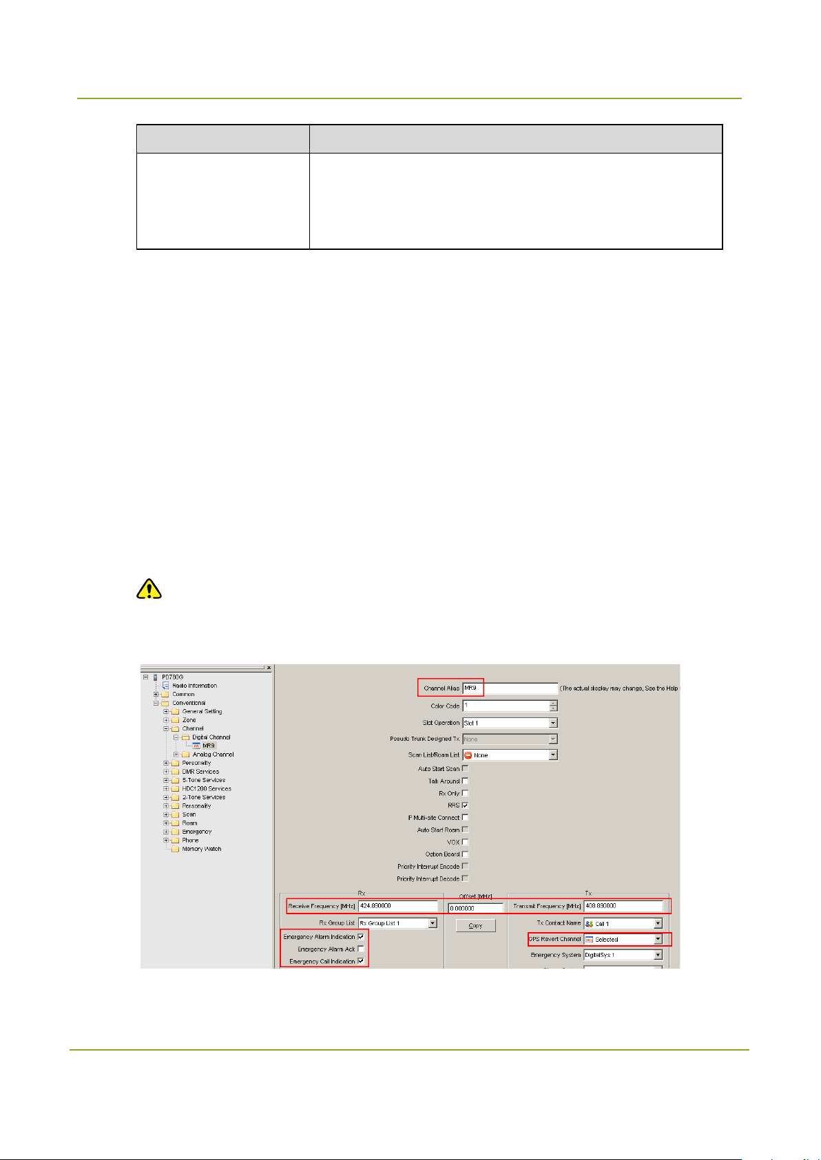
just need to set one channel for the portable radio. Ensure that the “GPS Revert Channel” parameter is
set to “Selected”.
Step 1 Go to “Conventional -> Channel -> Digital Channel”.
Step 2 Set the following parameters.
Caution
You must select the following options: “Emergency Alarm Indication” and “Emergency Call
Indication”.
62

SmartDispatch-Net Configuration Guide
Programming the Portable Radio
Two dispatch stations in a group
If two dispatch stations are employed in a group to transmit the audio signals and GPS data separately,
you need to set two channels for the portable radio. One is used to transmit the audio signals while the
other to transmit the GPS data. More importantly, their slots must be different.
Step 1 Go to “Conventional -> Channel -> Digital Channel”.
Step 2 Set the following parameters.
Note
Click the icon to add a channel.
Setting the voice channel for audio transmission
Note
Do set the “GPS Revert Channel” to “MR8-GPS”.
Setting the channel for GPS data transmission
Note
Do set the “GPS Revert Channel” to “Selected”.
Activating the Pseudo Trunking feature
Step 1 Go to “Conventional -> Channel -> Digital Channel”.
Step 2 Set the “Slot Operation” to “Pseudo Trunk”.
63

Programming the Portable Radio
SmartDispatch-Net Configuration Guide
Deactivating the Pseudo Trunking feature
Step 1 Go to “Conventional -> Channel -> Digital Channel”.
Step 2 Select the same slot specified for the dispatch station from the “Slot Operation” drop-down list.
7.4 Encryption
You should set the encrypt key for the portable radio before using the Voice Encryption feature. Make
sure that this key is identical with that of the repeater and SmartDispatch Client.In addition, you should
configure the appropriate parameter in the SmartDispatch Gateway (See the description of “Encrypt
Slot” in “9.3 Repeater Settings”).
Follow the steps below to set the encrypt key:
Step 1 Go to “Conventional -> DMR Services -> Encrypt” in the left navigation tree.
Step 2 Select “Encrypt” and create an encrypt key. Ensure that this key is the same with that of the
repeater and SmartDispatch.
Parameter Description
64
SmartDispatch-Net Configuration Guide
Programming the Portable Radio
the “Key
Parameter Description
Defines the length of the key you enter. Currently there are
Encrypt Key Length
Key ID The ID must be unique.
Key Alias The alias must be unique.
Key Value
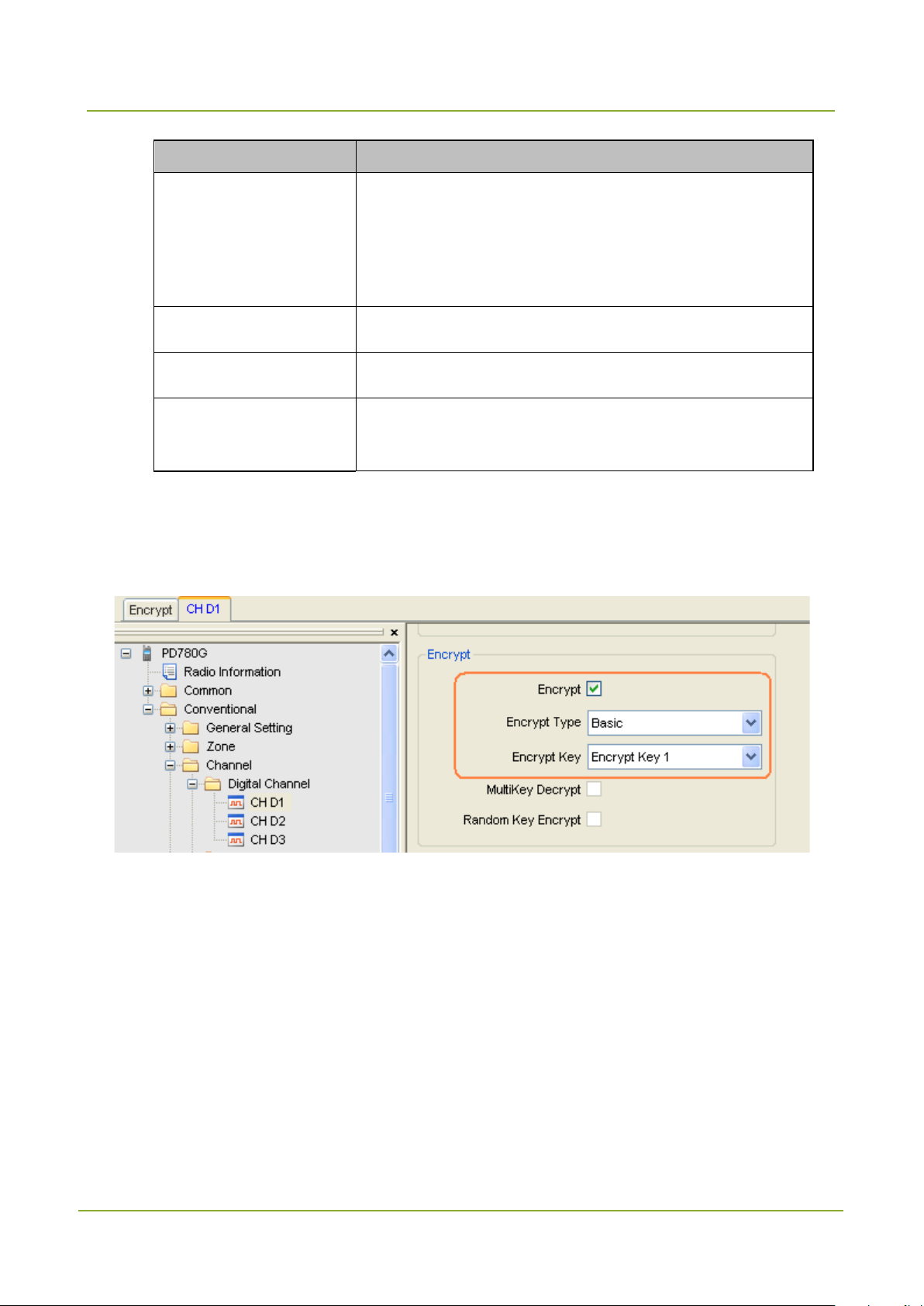
Step 3 Go to “Conventional -> Channel -> Digital Channel”.
Step 4 Set the encrypt key for the channel on which the encrypted voice is transmitted.
three options: 10, 32 and 64 characters. As long as you set
this parameter, you can enter the encrypt key in
Length”.
Be sure to enter the hexadecimal numbers. The length of key
value is subject to the settings in the “Key Length”.
7.5 Telemetry
Through the SmartDispatch Client, you can remotely monitor the status of the external device connected
to the radio, as well as controlling it.
65

Programming the Portable Radio
SmartDispatch-Net Configuration Guide
To apply the Telemetry feature, you should connect the monitored device to the GPIO port of the radio,
define the telemetry commands (see “10.9 Telemetry”) and enable the radio in the following steps to
respond to the commands.
Step 1 Go to “Conventional -> General Setting -> Telemetry” in the left navigation tree.
Step 2 Configure how the radio responds to the received telemetry commands.
In SmartDispatch Client, Feature 1 – Feature 6 of Telemetry are corresponding to
“Telemetry VIO 1” – “Telemetry VIO 6” of the radio respectively. Pay attention to this
when setting the Telemetry features. For example, if you select Feature 1 in
SmartDispatch, you must configure the Telemetry VIO 1 for the radio.
Accordingly, select the corresponding “Action” o f th e r ad io according to the preset
command. For example, if you set the command “Send Pulse Command” in
SmartDispatch, you need to select “On Pulse Comm an d ” fo r th e r ight VIO port of the
radio.
Step 3 Set the GPIO port corresponding to the preset VIO port of the radio. The radio will respond to
the telemetry command through this port.
66

SmartDispatch-Net Configuration Guide
Programming the Portable Radio
Send Status
Upon the receipt of “Send Pulse Command”, the radio’s GPIO port
On Toggle Voltage
Different telemetry responses need different GPIO voltages. Here we take low level of the GPIO port as
the active level.
Action GPIO Port Response
Upon the receipt of “Send Query Status Command”, the radio will send the
Command
On Pulse Command
Command
On Active/Inactive
Voltage Command
level status of its GPIO port (corresponding to the VIO port) to the
SmartDispatch.
(corresponding to the VIO port) will output an active level with specific pulse
width (e.g. : 200ms).
Upon the receipt of “Send Toggle Voltage Command”, the radio will toggle the
level of the GPIO port (corresponding to the VIO port). For example, currently
the GPIO port is using high level, and it will toggle to low level as soon as the
radio receives this command.
Upon the receipt of “Send Active Voltage Command”, the radio’s GPIO port
(corresponding to the VIO port) will output an ac tive level (here we t ake
low level as the active level).
Upon the receipt of “Send Inactive Voltage Command”, the radio’s GPIO
port (corresponding to the VIO port) will output an inactive level (here we
take high level as the inactive level).
67
Programming the Portable Radio
SmartDispatch-Net Configuration Guide
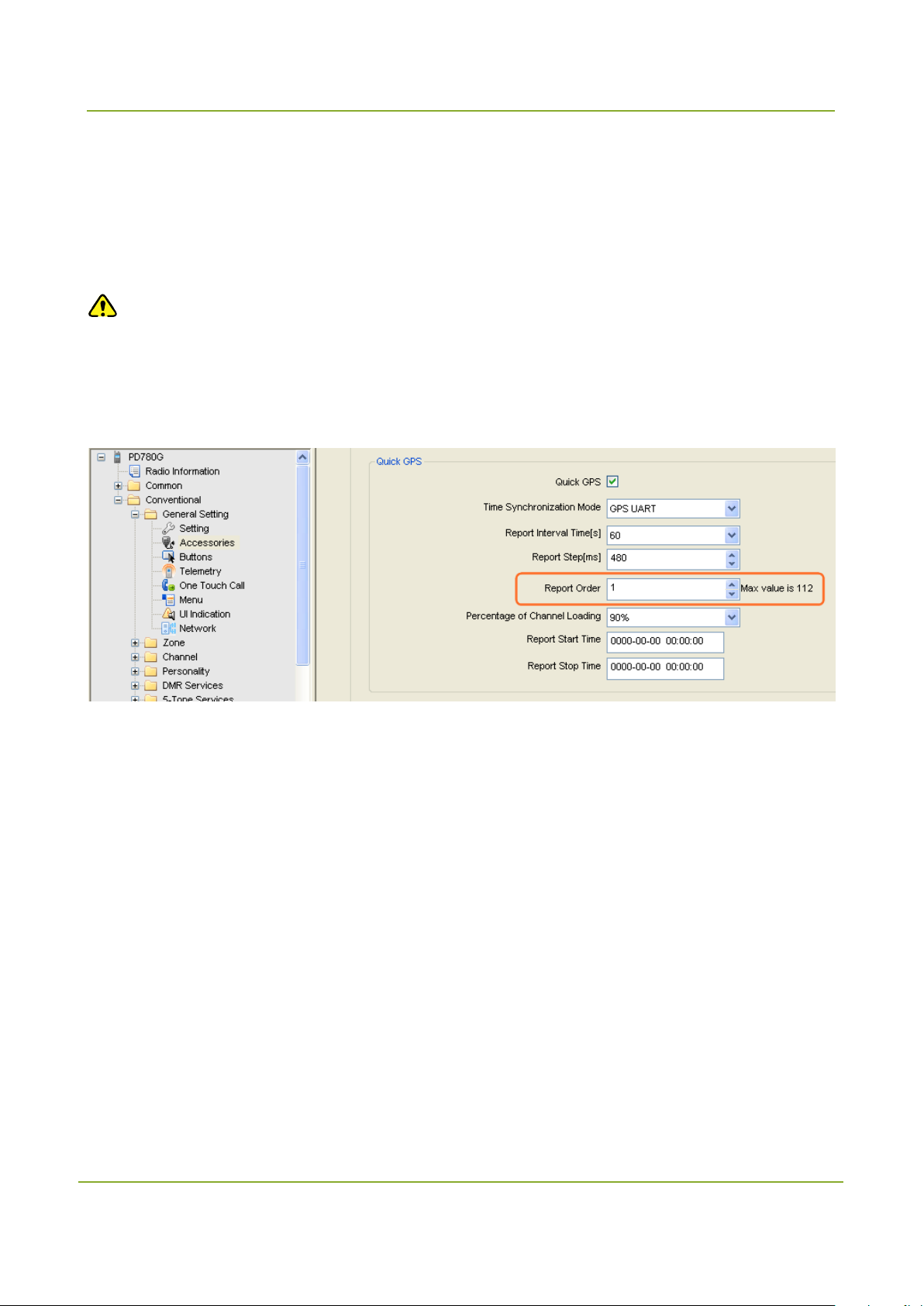
7.6 Quick GPS
When the Quick GPS feature is enabled for the radio, the GPS polling will be transmitted more securely
and efficiently.
To set this feature, go to “Conventional -> General Setting -> Accessories” in the left navigation tree.
Caution
Different report orders are required on radios with the Quick GPS feature enabled. You need to
set this parameter for the radio based on its actual report order.
The other parameters in the “Quick GPS” settings shall be set to the same values respectively
with those set for other radios whose Quick GPS feature is also enabled.
68

SmartDispatch-Net Configuration Guide
Configuring the SmartDispatch Server
8. Configuring the SmartDispatch Server
Caution
Make sure that your computer is not in the power saving mode; otherwise, the SmartDispatch
service will be stopped, resul ting in system malfunctions.
Double-click the shortcut icon “SmartDispatch Server Config Tool” on the desktop to enter the following
main window.
8.1 Basic Settings
Step 1 Specify the path for saving the recordings and leave the other parameters to their default
settings.
69

Configuring the SmartDispatch Server
SmartDispatch-Net Configuration Guide
th the SmartDispatch Client and SmartDispatch
Gateway access the SmartDispatch Server via this
G.711 and G.729. The audio codec in the
Parameter Description Example
Local IP Address Sets the IP address of SmartDispatch Server. 127.0.0.1
Bo
Command Port
VOIP Port
Audio Codecs
port.
Sets the VOIP start port of the SmartDispatch Server
for audio communication. Up to 400 ports are reserved
for audio communication. For example, if the start port
number is 17000, the port range will be 17000–17399.
SmartDispatch supports two audio formats including
SmartDispatch system must be identical.
61400
17000
G.711u
Caution
Be sure to select “G.711u” if you use the repeater.
Record File Defines the path for storing the recordings.
D:\Record
70
SmartDispatch-Net Configuration Guide
Configuring the SmartDispatch Server
, the radio will
its GPS information after all the
ioning this radio exit
Parameter Description Example
Files
When this option is selected
automatically go on polling the GPS information
after all the dispatchers who are positioning this
Auto
Subscription
GPS
Step 2 Click “OK” to finish.
radio exit their SmartDispatch. It is easier for the
dispatchers to position the radio continuously.
If you don’t select this option, the radio will stop
polling
dispatchers who are po sit
their SmartDispatch.
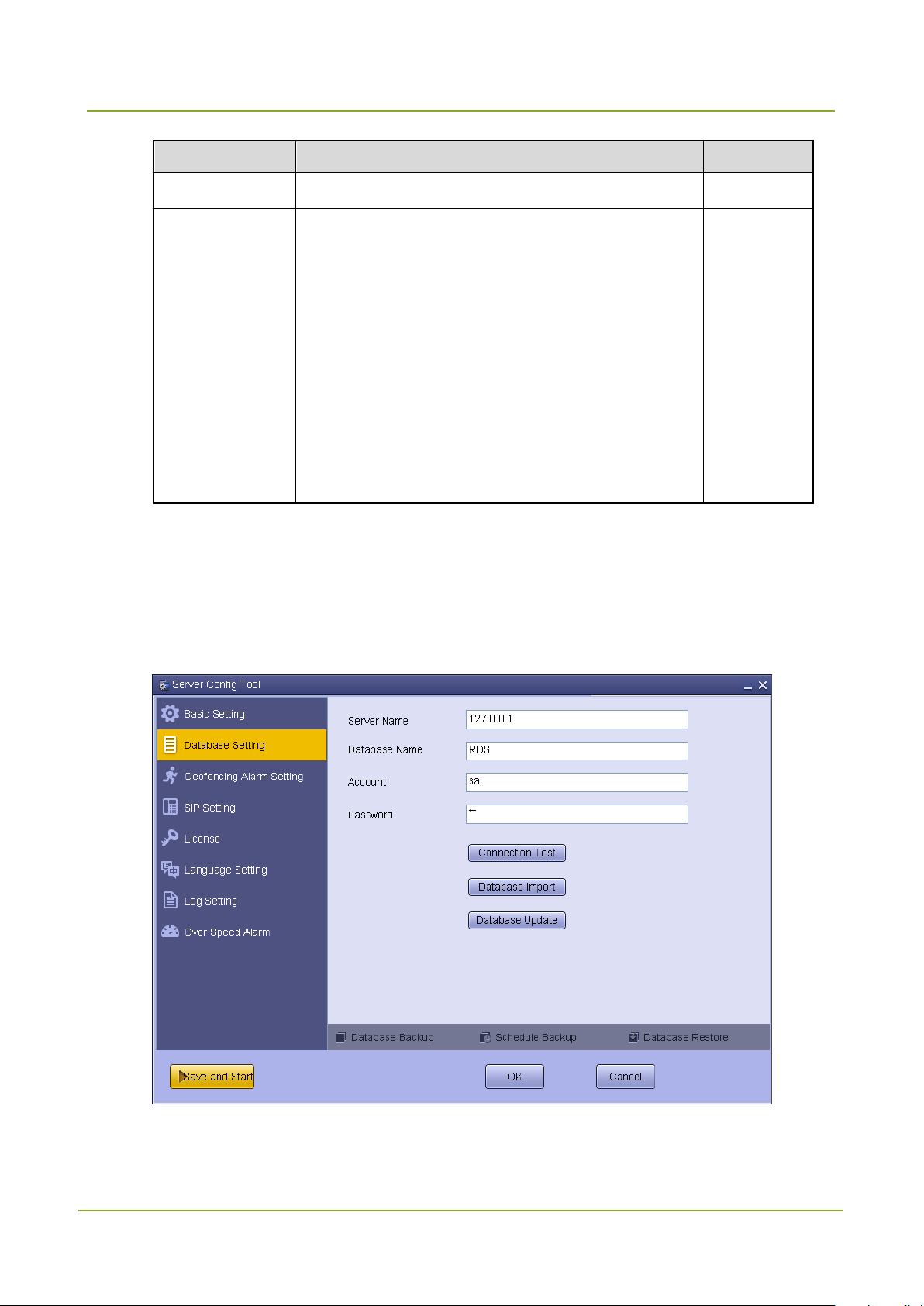
8.2 Database Settings
Step 1 Click “Database Setting”.
Step 2 Set the following parameters.
0:05:00
71

Configuring the SmartDispatch Server
SmartDispatch-Net Configuration Guide
Parameter
Description Example
Sets the name of the server where the database
is installed. It consists of the computer name
Server
Name
and database instance name.
If there is only one database in the computer,
you can enter the IP address (127.0.0.1) in this
field.
Database
Sets the alias of the database. RDS
Name
Sets the database account. Be sure to enter
Account
“sa” in this field.
Password Sets the database password. 123456
Step 3 Import the data to the database or upgrade the database.
Caution
The database can be connected successfully only when you import the data to it or upgrade
it in advance.
X09235D\SQLEXPRESS
sa
If you have already installed a lower version, you can click “Database Update” to upgrade the
database.
72

SmartDispatch-Net Configuration Guide
Configuring the SmartDispatch Server
Step 4 Click “Connection Test” to check the availability, and then click “OK” on the pop-up window.
Step 5 Click “OK” in the window to finish.
73

Configuring the SmartDispatch Server
SmartDispatch-Net Configuration Guide
8.2.2 Backing up the Database
As the database and recording file are vital in the SmartDispatch system, you should back up them
regularly to guard against data loss.
You can schedule the backup to occur automatically or back up the data manually. The backup file is
saved as a .zip file in the designated directory using this format: Hytera_RDS_BAKyyymmdd_X.zip” (for
example: Hytera_RDS_BAK20121224_0.zip).
To backup the data manually, do as follows:
You can initiate a manual backup after setting the following parameters.
Click “Database Backup” and set the parameters, finally click “OK” to save your settings.
Parameter Description
Directory Specifies the location of the backup file.
Sets which kind of data you want to back up. You can choose to back
Backup
up the data or recording file.
Sets whether to delete the data regularly. After you select this option,
Remove after backup
Remove old data over [?]
days
you are allowed to set the related parameter. Make sure that the data
is backed up and archived properly before you remove it.
Enters a value. All data older than the specified days will be removed.
74

SmartDispatch-Net Configuration Guide
Configuring the SmartDispatch Server
Parameter Description
Data Sets whether to delete the data.
Audio Sets whether to delete the recording file.
To back up the data automatically, do as follows:
The database and recordings can be automatically backed up by month or week.
Click “Schedule Backup” and set the parameters, finally click “OK” to save your settings.
Parameter Description
Path Specifies the location of the backup file.
Enable Backup
Data Sets whether to automatically back up the data.
Audio Sets whether to automatically back up the recording file.
Per Month
Sets whether the automatic backup is activated. When you select
this option, you are allowed to set the related parameter.
Specified which days of the month that an automatic backup should
75

Configuring the SmartDispatch Server
SmartDispatch-Net Configuration Guide
you select this
emove old data over [?]
days will be
Per Week
Parameter Description
occur. This parameter must be work with the “Time” parameter.
Specified which day of the week that an automatic backup should
occur. This parameter must be work with the “Time” parameter.
Sets the exact time on the specified day that an automatic backup
Time
Remove
R
days
Data Sets whether to delete the data.
Audio Sets whether to delete the recording file.
should run. This parameter must be work with the “Per Month” and
“Per Week” parameters.
Sets whether to delete the data regularly. After
option, you are allowed to set the related parameter. Make sure that
the data is backed up and archived properly before you remove it.
Enters a value. All data older than the specified
removed.
8.2.3 Restoring the Database
Caution
You must restart the server and log in to the SmartDispatch Client again after the database is
restored.
If the data is lost or the oldest database needs to be restored, you can restore the data from a .zip
archive.
Step 1 Click “Restore Database” and to select the backup file, then click “Restore” to restore the
database.
76

SmartDispatch-Net Configuration Guide
Configuring the SmartDispatch Server
Step 2 Click “Save and Start” to restart the server.
Step 3 Shut down the SmartDispatch client and log in to it again, to view the recovery data.
8.3 Geofencing Alarm Settings
Step 1 Click “Geofencing Alarm Setting”.
Step 2 Set the following parameters according to your actual requirements.
Parameter Description Example
Buffer Distance
Sets the buffer distance for triggering a geofencing
0
alarm.
77

Configuring the SmartDispatch Server
SmartDispatch-Net Configuration Guide
Sets the buffer time period for triggering a
Parameter Description Example
Buffer Time
Alarm Message
0
geofencing alarm.
Edits the message indicating the geofencing alarm.
The SmartDispatch Client will send this message to
Alarm.
the subscriber once he/she is out of the designated
region.
78

SmartDispatch-Net Configuration Guide
Configuring the SmartDispatch Server
Edits the message indicating canceling of the
geofencing alarm. The SmartDispatch Client will
Parameter Description Example
Cancel
Cancel Alarm.
Alarm Message
Step 3 Click “OK” to finish.
send this message to the subscriber after he/she
goes back to the designated region.
8.4 SIP Settings
SmartDispatch can access the telephone switch to communicate with the telephone subscribers. To be
specific, the SmartDispatch Server establishes the SIP connection with the telephone switch, which
communicates with the telephone. In this way, SmartDispatch can communicate with the telephone
subscriber. During the SIP connection, it is required to authenticate the account first.
Step 1 Click “SIP Setting” and select the “Enable SIP” option.
Step 2 Set the following parameters.
Parameter Description Example
Enable SIP
Sets whether the SIP telephone can access
√
79

Configuring the SmartDispatch Server
SmartDispatch-Net Configuration Guide
Client first for call request. This message
consists of that prefix and t he telephone
For details, please consult your network
For details, please consult your network
etwork management
Parameter Description Example
the SmartDispatch system. If you select this
option, it indicates that this feature is enabled.
This port is used by the SmartDispatch Server
Local Port
Message Prefix
ID
Password
to establish connection via the SIP protocol.
The remote end is IP-PBX.
Sets the prefix of the SIP call. If the portable
radio initiates a call to the telephone, it will
send the text message to the SmartDispatch
number.
Sets the user name specified in the IP-PBX.
management administrator.
Sets the password specified in the IP-PBX.
management administrator.
5060
SIP:
12345
123456
Sets the IP address of the switch and the port
defined in the SIP protocol. For details, please
Domain
consult your n
administrator.
Step 3 Click “OK” to finish.
127.0.0.1:5060
8.5 License
Click “License” to view the license information.
You can have a free trial on this product for three months. For its normal operation, please contact our
customer service center to obtain the License, and import your License by clicking “Load License File…”
here.
80
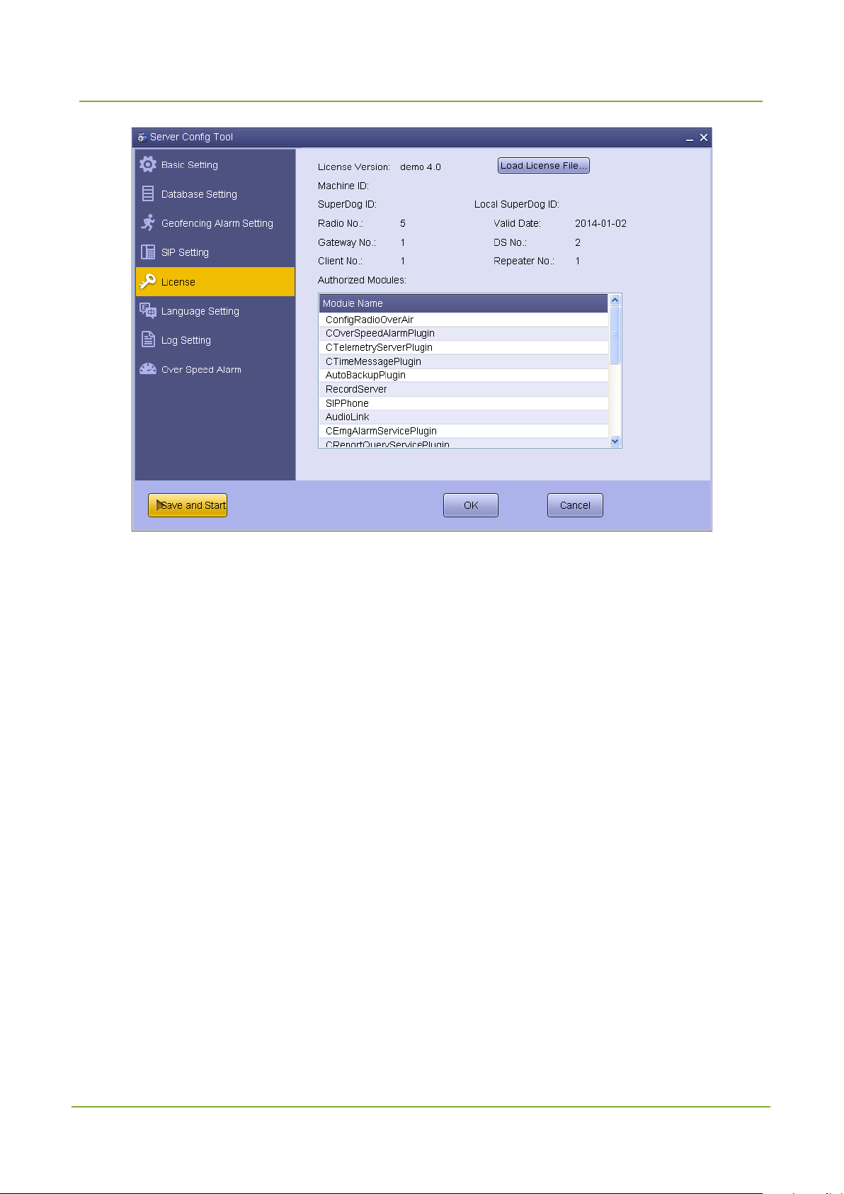
SmartDispatch-Net Configuration Guide
Configuring the SmartDispatch Server
8.6 Language Settings
Step 1 Click “Language Setting”.
Step 2 Select the language.
81

Configuring the SmartDispatch Server
SmartDispatch-Net Configuration Guide
Step 3 Click “OK” to finish.
8.7 Log Settings
Step 1 Click “Log Setting”.
Step 2 Set the following parameters as per your actual needs.
82

SmartDispatch-Net Configuration Guide
Configuring the SmartDispatch Server
Sets what kind of information will be
Parameter Description Example
Sets the maximum size of an i ndividual log
Log File Size
Log Type
Step 3 Click “OK” to save your settings.
Step 4 Click “Save and Start” to start the server service.
file.
recorded in the log file. There are four types
including System, Error, Warning and Info.
8.8 Over Speed Alarm Settings
Step 1 Click “Over Speed Alarm” and select “Enable”.
Step 2 Set the maximum speed and the buffer time.
Step 3 Click “OK” and then “Save and Start” to start the server service.
10
Error
83

Configuring the SmartDispatch Server
SmartDispatch-Net Configuration Guide
Sets the speed threshold of the radio
movement. Once the radio movement
20 Kilometers per
ires, the alarm will be
. Accordingly, when the radio
threshold for the same time period, the
Parameter Description Example
reaches this speed for a certain time period
Max Speed
Buffer Time
(i.e. the “Buffer Time”), the over speed alarm
will be triggered. There are three units for
this parameter: Kilometers per hour, Knots
per hour and Miles per hour.
Sets the time period before the over-speed
radio triggers the over speed alarm. As soon
as this period exp
triggered and the SmartDispatch will send
the alarm message to the radio
automatically
1
hour
0
slows down and moves at a speed under the
SmartDispatch will send a message to the
84

SmartDispatch-Net Configuration Guide
Configuring the SmartDispatch Server
Parameter Description Example
radio to inform that the alarm is dismissed.
85

Configuring the SmartDispatch Gateway
SmartDispatch-Net Configuration Guide
9. Configuring the SmartDispatch Gateway
Caution
Make sure that your computer is not in the power saving mode; otherwise, the SmartDispatch
service will be stopped, resul ting in system malfunctions.
To en su r e n o r mal operation of the gateway server, connect the USB dog (for license
verification) to the SmartDispatch Server.
Double-click the shortcut icon “SmartDispatch Gateway Config Tool” on the desktop to enter the relevant
window.
9.1 Basic Settings
Step 1 Click “Basic Setting”.
Step 2 Set the following parameters.
Parameter Description Example
Local IP
Sets the IP address of the SmartDispatch
86
127.0.0.1
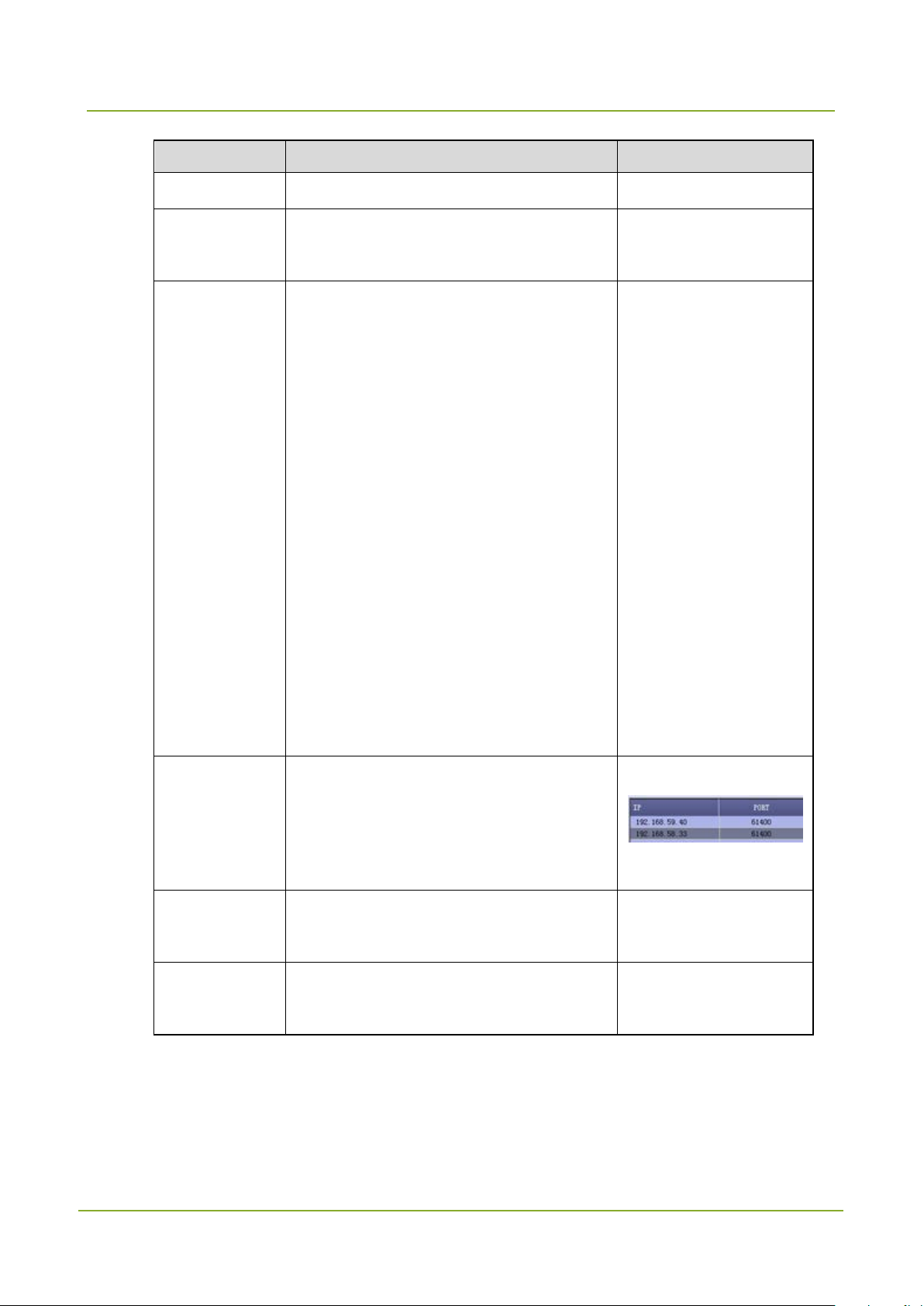
SmartDispatch-Net Configuration Guide
Configuring the SmartDispatch Gateway
Sets the port for accessing the
Local VOIP
s the VOIP start port of the
SmartDispatch Gateway for audio
communication. The system will reserve
sufficient ports for audio communication.
When the SmartDispatch Gateway is
of the
dispatch stations. For example, if the
SmartDispatch Gateway connects three
19005. However, when the
SmartDispatch Gateway connects to the
Displays all servers connected to the
SmartDispatch Gateway. One
SmartDispatch Gateway can contain 5
Sets the IP address for accessing the
Sets the port for accessing the
Parameter Description Example
Gateway.
Local Port
Port
SmartDispatch Server.
0
Set
connected to dispatch stations, the number
of the reserved ports is twice that
19000
dispatch stations and the start port number
is 19000, the reserved port numbers will be
19000 –
repeater, the number of the reserved ports
is fourfold that of the repeaters.
Server List
servers at most.
Server IP
SmartDispatch Server.
Server Port
SmartDispatch Server.
Step 3 Click in blank area of the “Server List” pane, and click “Add” to add a server.
If the SmartDispatch Gateway and SmartDispatch Server are installed on the same computer,
you can skip this step.
192.168.59.40
61400
87

Configuring the SmartDispatch Gateway
SmartDispatch-Net Configuration Guide
Step 4 Click “Save and Start”.
If you make any change in this tab, the button will change from “Start” to “Save and Start”
9.2 Dispatch Station Settings
Step 1 Click “Dispatch Station Setting”.
88

SmartDispatch-Net Configuration Guide
Configuring the SmartDispatch Gateway
Step 2 Click “Add” and set the following parameter. Click “Connection Test” to test whether the
dispatch station is connected properly. The prompt “Connect successfully” will appear after
successful connection.
89

Configuring the SmartDispatch Gateway
SmartDispatch-Net Configuration Guide
Sets the virtual IP address of the
dispatch station. It consists of four
stent with those of the IP
address defined in the Customer
For example, if the dispatch station
IP is 192.168.87.1, the virtual IP
Parameter Description Example
Sets the alias of the dispatch station.
Alias
Pseudo ID
Please refer to Section 3.2 Radio
Planning
Sets whether to enable or disable the
Pseudo feature. If you set this
parameter to 0, it means this feature
is disabled. As a result, the voice or
data is transmitted on the designated
slot. However, if the value is not 0,
the pseudo feature will be activated.
In this case, either slot 1 or slot 2 is
used to transmit the data or voice as
long as it is available. Accordingly,
the channel utilization is improved.
Please note that the Pseudo ID of
each repeater must be different.
MR7
0
Virtual IP
sections. The first three sections are
consi
Programming Software, while the last
section is one greater than that of the
IP address.
should be 192.168.87.2.
90
192.168.87.2

SmartDispatch-Net Configuration Guide
Configuring the SmartDispatch Gateway
Enable DS
Sets whether to enable the
If you use the microphone to talk,
will not be recorded. However, the
relevant call records involving the
GPS Dispatch
PS data
, unable to transmit
to set another dispatch station
Unchecked: the dispatch station
will transmit both the audio
Parameter Description Example
Tests whether the dispatch station is
connected properly.
Caution
Prior to perform the connection
test, make sure that the dispatch
station has already connected to
Connection
Test
the PC and been turned on. If this
test is failure, the dispatch station
Microphone
can not operate properly. If the
port is occupied, the alert
message will be given. Thus you
must stop the SmartDispatch
service first and then make the
connection test again.
microphone.
only the voice from the microphone
microphone still exist.
Checked: the dispatch station will
Station
only be us ed for G
transferring
the audio signal. Then you need
for audio transmission.
signal and GPS data.
91

Configuring the SmartDispatch Gateway
SmartDispatch-Net Configuration Guide
data station, unable to transmit
to set another dispatch station
for audio transmission. Only
when the dispatch station is
can the SmartDispatch
Unchecked: the dispatch station
will transmit both the audio
is checked, this option is not
is checked, this option is not
Parameter Description Example
Checked: the dispatch station will
only be used as the quick GPS
the audio signal. Then you need
Quick GPS
Speaker
Microphone
used to transmit quick GPS data
distinguish the quick and normal
GPS data.
signal and GPS data.
Sets the name of the speaker.
If the “GPS Dispatch Station” option
Speakers (SB 5.1 VX)
available.
Sets the name of the microphone.
If the “GPS Dispatch Station” option
Line-In (SB 5.1 VX)
Step 3 Click “OK” to finish.
9.3 Repeater Settings
Step 1 Click “Repeater Setting” and then click “Add” to add a repeater. Finally click “Save” to save the
settings.
available.
92

SmartDispatch-Net Configuration Guide
Configuring the SmartDispatch Gateway
Parameter Description Example
Radio ID Sets the SSI of the repeater. 92
Alias Sets the alias of the repeater. Repeater3
93

Configuring the SmartDispatch Gateway
SmartDispatch-Net Configuration Guide
site network, repeaters in
together to exchange the data and voice. In
However, if the value is not 0, the pseudo
as long as it is available. Accordingly, the
D of each repeater must be
Parameter Description Example
Sets the ID of the IP multi-site network. Each IP
Multi-site network has a unique ID. Within the
same IP Multi-
geographically dispersed location can be linked
IP Site ID
Pseudo ID
other words, when you send any command to
one repeater via SmartDispatch Client, other
repeaters in the same network will also receive
it.
Sets whether to enable or disable the Pseudo
feature. If you set this parameter to 0, it means
this feature is disabled. As a result, the voice or
data is transmitted on the designated slot.
feature will be activated. In this case, either slot
1 or slot 2 is used to transmit the data or voice
channel utilization is improved. Please note that
the Pseudo I
1
0
different.
Slot1 Slot 1
Alias Sets the alias of the slot. Slot1
Sets the ID of the repeater. Within the same IP
Multi-site network, if the radio wants to
communicate with the repeater, their subnet
Subnet ID
IDs must be identical. However, in the CPS,
you are allowed to program the subnet ID for
the radio rather than for the repeater. That is
why you must set this ID for the repeater here.
21
94

SmartDispatch-Net Configuration Guide
Configuring the SmartDispatch Gateway
Checked: the slot can only transfer quick
SmartDispatch distinguish the quick and
local data
This option must be selected if you need t o
site network, if the radio wants to
communicate with the repeater, their subnet
Checked: the slot can only transfer quick
Parameter Description Example
GPS data, and an other slot is needed t o
transfer audio signal. Only when the slot is
used to transmit quick GPS data can the
Quick GPS
normal GPS data.
Unchecked: the slot will transfer both audio
signal and GPS data.
If you select this option, the slot is in charge of
GPS Repeater
Local Slot
Encrypt Slot
RTP Type
Slot2 Slot 2
Alias Sets the alias of the slot. Slot2
transmitting the GPS data. Otherwise, this slot
is used to transmit the audio signal.
The slot is only used for
transmission.
encrypt the voices. Be sure to set “RTP Type”
to “RTP_SELP”.
Sets the audio format for transmission. Be sure
to set it to “RTP_SELP”.
Sets the ID of the repeater. Within the same IP
Multi-
RTP_SELP
Subnet ID
Quick GPS
IDs must be i dentical. However, in the CPS,
you are al lowed to program the subnet ID for
the radio rather than for the repeater. That is
why you must set this ID for the repeater here.
21
95
 Loading...