

Page 1

RRU3800F080 User Guide
Document Version: V1.0
Release Date: 11-2018
Page 2

Copyright Information
Hytera is the trademark or registered trademark of Hytera Communications Co., Ltd. (the Company) in
PRC and/or other countries or areas. The Company retains the ownership of its trademarks and product
names. All other trademarks and/or product names that may be used in this manual are properties of their
respective owners.
The product described in this manual may include the Company’s computer programs stored in memory or
other media. Laws in PRC and/or other countries or areas protect the exclusive rights of the Company with
respect to its computer programs. The purchase of this product shall not be deemed to grant, either directly
or by implication, any rights to the purchaser regarding the Company’s computer programs. Any of the
Company’s computer programs may not be copied, modified, distributed, decompiled, or
reverse-engineered in any manner without the prior written consent of the Company.
Disclaimer
The Company endeavors to achieve the accuracy and completeness of this manual, but no warranty of
accuracy or reliability is given. All the specifications and designs are subject to change without notice due
to continuous technology development. No part of this manual may be copied, modified, translated, or
distributed in any manner without the express written permission of us.
We do not guarantee, for any particular purpose, the accuracy, validity, timeliness, legitimacy or
completeness of the Third Party products and contents involved in this manual.
If you have any suggestions or would like to learn more details, please visit our website at
http://www.hytera.com.
Changes or modifications not expressly approved by the party responsible for compliance could void the
user’s authority to operate the equipment.
This equipment has been tested and found to comply with the limits for a Class B digital device, pursuant to
Part 15 of the FCC Rules. These limits are designed to provide reasonable protection against harmful
interference in a residential installation. This equipment generates, uses and can radiate radio frequency
energy and, if not installed and used in accordance with the instructions, may cause harmful interference to
radio communications. However, there is no guarantee that interference will not occur in a particular
installation.
If this equipment does cause harmful interference to radio or television reception, which can be determined
Page 3

by turning the equipment off and on, the user is encouraged to try to correct the interference by one or
more of the following measures:
-- Reorient or relocate the receiving antenna.
-- Increase the separation between the equipment and receiver.
-- Connect the equipment into an outlet on a circuit different from that to which the receiver is connected.
-- Consult the dealer or an experienced radio/TV technician for help.
This equipment complies with FCC radiation exposure limits set forth for a uncontrolled environment. This
equipment should be installed and operated with minimum distance 11m between the radiator and your
body. This transmitter must not be co-located or operating in conjunction with any other antenna or
transmitter. This equipment complies with IC RSS-102 radiation exposure limits set forth for a uncontrolled
environment. This equipment should be installed and operated with minimum distance 11m between the
radiator and your body.
Cet équipement est conforme aux limites d'exposition aux radiations IC CNR-102 établies pour un
environnement uncontrôlé. Cet équipement doit être installé et utilisé avec une distance minimale de 11 m
entre
le radiateur et votre corps.
This device contains licence-exempt transmitter(s)/receiver(s) that comply with Innovation, Science and
Economic Development Canada’s licence-exempt RSS(s). Operation is subject to the following two
conditions:
(1) This device may not cause interference.
(2) This device must accept any interference, including interference that may cause undesired operation of
the device.
L’émetteur/récepteur exempt de licence contenu dans le présent appareil est conforme aux CNR
d’Innovation, Sciences et Développement économique Canada applicables aux appareils radio exempts
de licence. L’exploitation est autorisée aux deux conditions suivantes :
(1) L’appareil ne doit pas produire de brouillage;
(2) L’appareil doit accepter tout brouillage radioélectrique subi, même si le brouillage est susceptible d’en
compromettre le fonctionnement.
Page 4

Page 5

User Guide
Contents i
Contents
Documentation Information ..................................................................................................................... 1
1. Product Overview .................................................................................................................................. 2
2. Packing List ........................................................................................................................................... 3
3. Familiar with the Product ..................................................................................................................... 4
3.1 RRU Appearance ............................................................................................................................... 4
3.2 RRU Interfaces .................................................................................................................................. 4
3.3 RRU Indicators .................................................................................................................................. 5
4. Product Installation ............................................................................................................................... 7
4.1 Safety Information .............................................................................................................................. 7
4.2 Installation Flow ................................................................................................................................. 8
4.3 Installation Preparations .................................................................................................................... 9
4.3.1 Environment Requirements ..................................................................................................... 9
4.3.2 Instruments and Tools ............................................................................................................ 10
4.3.3 Materials ................................................................................................................................ 10
4.4 Installing the Device ......................................................................................................................... 10
4.4.1 Mounting Kits ......................................................................................................................... 10
4.4.2 Installing the RRU ................................................................................................................... 11
4.5 Installing Cables .............................................................................................................................. 14
4.5.1 Cabling Requirements ........................................................................................................... 14
4.5.2 Cable Connection Diagram .................................................................................................... 16
4.5.3 Installing PGND Cable ........................................................................................................... 16
4.5.4 Installing RF Jumper .............................................................................................................. 17
4.5.5 Installing RRU Power Cord .................................................................................................... 18
4.5.6 Installing CPRI Fiber .............................................................................................................. 18
4.5.7 Installing Monitoring Cable .................................................................................................... 19
4.5.8 Installing GNSS Jumper ........................................................................................................ 19
4.6 Installation and Power-on Check ..................................................................................................... 19
4.6.1 Installation Check ................................................................................................ .................. 19
4.6.2 Power-on Check .................................................................................................................... 20
5. Operation and Maintenance ............................................................................................................... 21
5.1 Powering On RRU ........................................................................................................................... 21
5.2 Powering Off RRU ........................................................................................................................... 21
6. Troubleshooting .................................................................................................................................. 22
7. Care and Cleaning ............................................................................................................................... 23
8. Technical Specifications .................................................................................................................... 24
9. Abbreviations ...................................................................................................................................... 27
Page 6

Page 7
User Guide
Documentation Information 1
Documentation Information
This section introduces the target readers, conventions and revision history.
Target Readers
This document applies to the following readers:
Technical support engineers
Maintenance engineers
Installation/commissioning engineers
Documentation Conventions
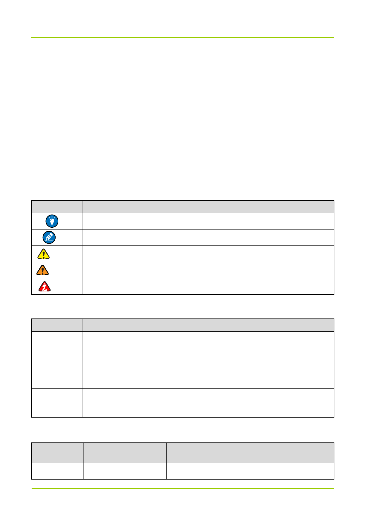
Icon Conventions
Icon
Description
贴士
Tip
Indicates information that can help you make better use of your product.
备注
Note
Indicates references that can further describe the related topics.
注意
Caution
Indicates situations that could cause data loss or device damage.
警告
Warning
Indicates situations that could cause minor personal injury.
危险
Danger
Indicates situations that could cause major personal injury or even death.
Notation Conventions
Convention
Description
""
The quotation marks enclose the name of a software interface element. For example,
click "OK".
Bold
The text in boldface denotes the name of a hardware button. For example, press the
PTT
key.
->
The symbol directs you to access a multi-level menu. For example, to select "New"
from the "File" menu, we will describe it as follows: "File -> New".
Revision History
Document
Version
Product
Version
Release
Date
Description
00
V1.0
11-2018
Initial release.
Page 8

User Guide 2
1. Product Overview
Radio Remote Unit (RRU) extends the RF module in the BS to the far-end RF unit through optical fibers to
complete baseband signal and RF signal processing. The RRU and Base Band Unit (BBU) jointly compose
a BS.
Main features of the RRU:
Receiving downlink baseband data sent from the BBU, and sending uplink baseband data to the BBU
to implement communication with the BBU.
Receiving the RF signal from the antenna feeder system, changing the received signal to intermediate
frequency signal through down conversion, performing amplification and analog-to-digital conversion
(A/D conversion) for the signal, completing downlink signal filtering and digital-to-analog conversion
(D/A conversion), and sending the RF signal to the transmit frequency band through up-conversion.
Providing the received signal and transmitted signal multiplexing function of RF channel to enable the
received signal and transmitted signal to share one antenna channel, and providing the filtering function
of received signal and transmitted signal.
Page 9
User Guide
3
2. Packing List
The packaging box contains the following items. If any items are missing or damaged, please contact
Hytera or your local distributor.
Item
Quantity
Item
Quantity
Main unit
1
Document suite
1 set
Mounting kits
1 set
/
/
备注
Note
The pictures in the manual are used for reference only. Please refer to the actual product.
Page 10
User Guide 4
3. Familiar with the Product
3.1 RRU Appearance
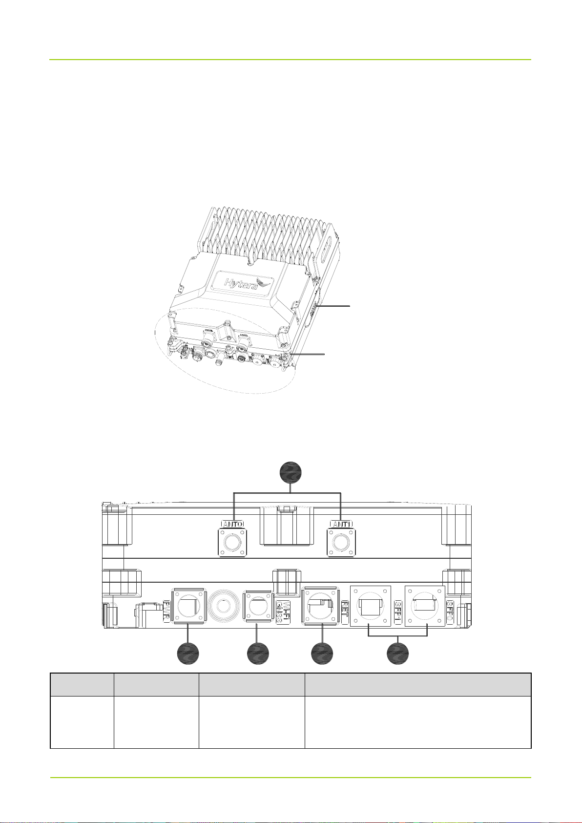
The RRU is designed in the modular structure. The external interfaces and indicators of the RRU are
located at the bottom and the right side of the module respectively. The figure below shows the
appearance of the RRU.
RRU indicator
RRU interface
3.2 RRU Interfaces
The figure below shows the positions of interfaces at the bottom panel of the RRU.
54432
1
No.
Identifier
Connector
Description
1
ANT0/ANT1
DIN
Two antenna connectors, used to transmit and
receive the RF signal.
Page 11
User Guide
5
No.
Identifier
Connector
Description
2
Power Indicator
/
Power interface, used to connect to the external
power system.
Supporting the -48V DC input.
3
GNSS
N-F (GNSS)
GNSS interface, used to connect to the
GPS/Beidou Navigation Satellite System.
4
RET
Aviation connector
Dry contact interface, connected to the external
monitoring device through the monitoring cable.
Supporting up to 115,200 bps.
5
SFP0/SFP1
SFP/SFP+female
type
CPRI interface, connected to the BBU or
lower-level RRU through the optical fiber.
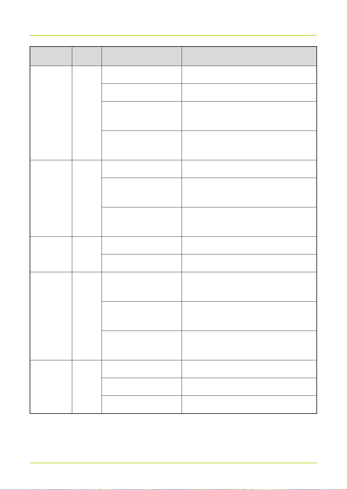
3.3 RRU Indicators
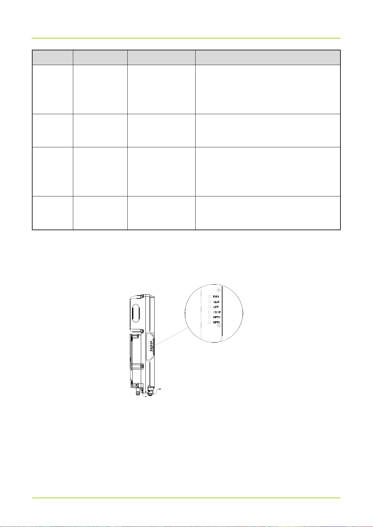
The RRU is provided with six indicators, which are used to indicate the RRU operating status. The RRU
indicators are located on the right panel of the RRU, as shown below.
Page 12
User Guide 6
LED
Indicator
Color
Status
Description
RUN
Green
Steady off
No power input or device failure
Steady on
Power input available, but the device fails
Blinking slowly (on for 1s
and off for 1s)
The device is running normally.
Blinking quickly (on for
0.125s and off for 0.125s)
The device is loading software or the device is
not operating.
ALM
Red
Steady off
The device does not report any alarm.
Steady on
The device reports an alarm, and the board
needs to be replaced.
Blinking
The device reports an alarm arising from the
related interface failure.
ACT
Green
Steady on
No service is operating on the device.
Blinking
Service is operating on the device.
VSWR
Red
Steady off
The device does not report the Voltage
Standing Wave Ratio (VSWR) alarm.
Blinking slowly
Exception of one or multiple channels is
detected after the cell is established.
Blinking rapidly
One or more ports report the VSWR alarm
during startup.
SFP0/SFP1
Green
Steady off
The CPRI fiber link is abnormal.
Steady on
The CPRI fiber link is normal.
Blinking
Data is being transmitted on the CPRI link.
User Guide
Page 13

7
4. Product Installation
4.1 Safety Information
Before performing any operation, read the following precautions and operation instructions carefully to
ward off potential risks.
Regulations and Specifications
Observe local regulations and specifications when installing the equipment.
Power supply
危险
Danger
Direct contact or indirect contact (through moist objects) with the high voltage or mains
electricity may result in an electric shock.
Nonstandard or incorrect operations may lead to accidents such as a fire or electric shock.
Never wear conductive articles such as watches, bracelets or rings during operation.
Do use dedicated tools during high voltage or AC operations.
Take necessary measures to prevent entry of moisture into the device operating under a moist
environment.
Make sure the lightning-proof grounding is implemented for the device to prevent it from being
damaged by lightning strikes.
Disconnect the device from the power supply before installing or removing it.
Check the cable and the label on it to ensure correct connection.
Make sure that the device is well grounded before connecting it to the power supply.
Disconnect the device from the power supply if you find water or other liquids in the device.
Make sure the power switch is toggled to the "Off" position before installing the device.
Working at Height
Work at height refers to work performed at a height more than 2 m above the ground. Pay attention to the
following items during the work at height.
Stop the work at height in case of hazardous conditions such as thunder and lightning, rain, snow, gale
above scale 6, and steel pipe with rainwater.
Define a hazardous zone on the work site at height, set an obvious sign, and prevent unauthorized
persons from entering the area.
Page 14
User Guide 8
Do not pile scaffolds, gangplanks or other sundries on the lower ground of the work area at height.
Ground workers are not allowed to stay under the work area at height or pass through it.
People who work at height should not throw objects to the ground from the high altitude or to the high
altitude from the ground. Instead, they should use strong ropes, hanging baskets, overhead vehicles, or
cranes to transport objects.
Take sound safety actions such as wearing the hamlet and safety belt properly.
Do wear heat-retaining clothes when working in cold areas.
Make sure that the ladder is safe for use, and overload is strictly prohibited.
People who work at height should handle and use all instruments and tools with care to avoid falling to
injure others.
Do not frolick when working at height or sleep in the work area at height.
Personnel
The person who performs equipment operations must have acquired the basic knowledge of safety
operations, received professional training, and obtained the corresponding operation qualifications.
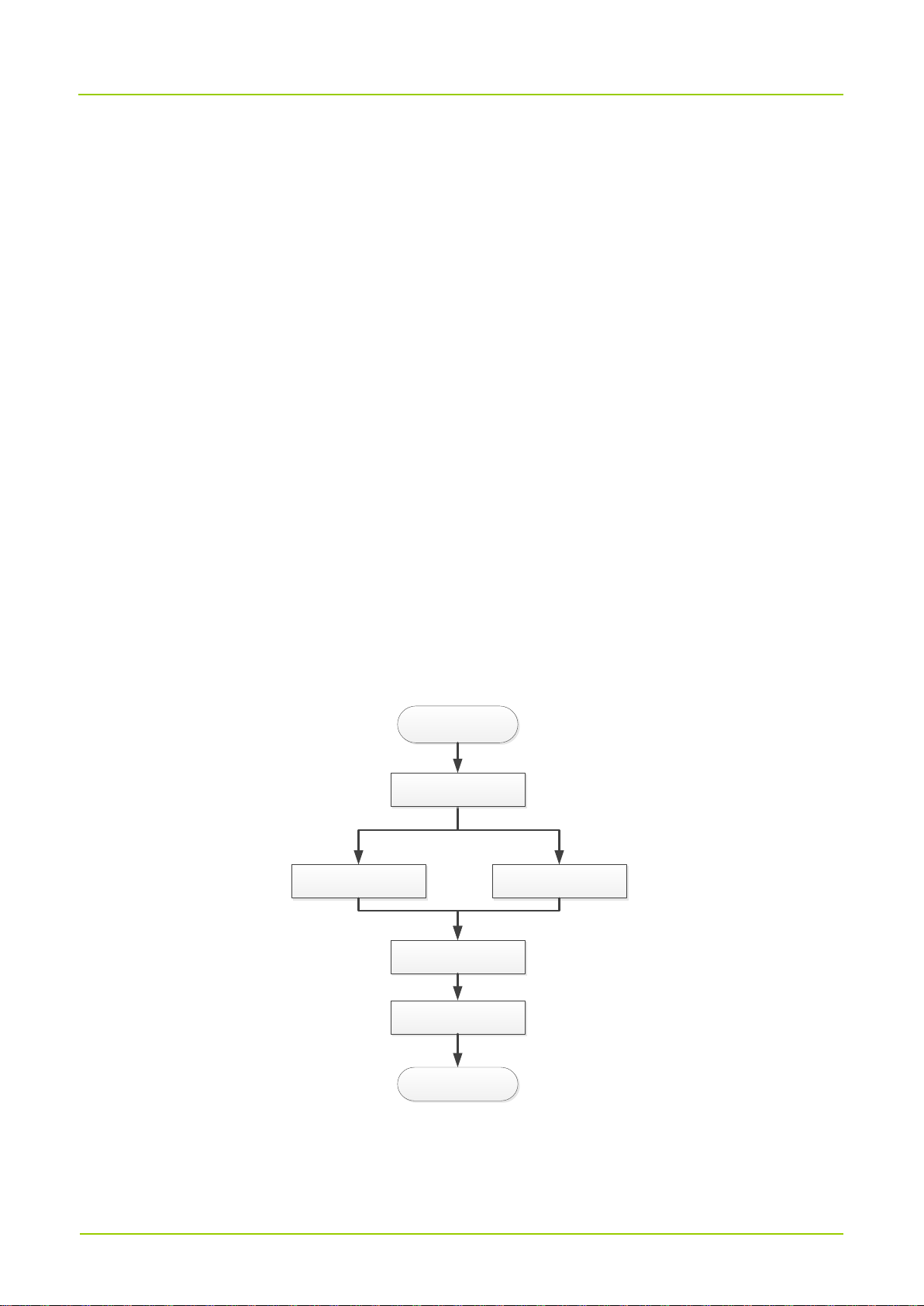
4.2 Installation Flow
The figure below shows the RRU installation flow.
Pole-mounted
installation
Start
Suspended installation
Installation and
power-on check
End
Install cables
Installation preparations
Page 15
User Guide
9
4.3 Installation Preparations
4.3.1 Environment Requirements
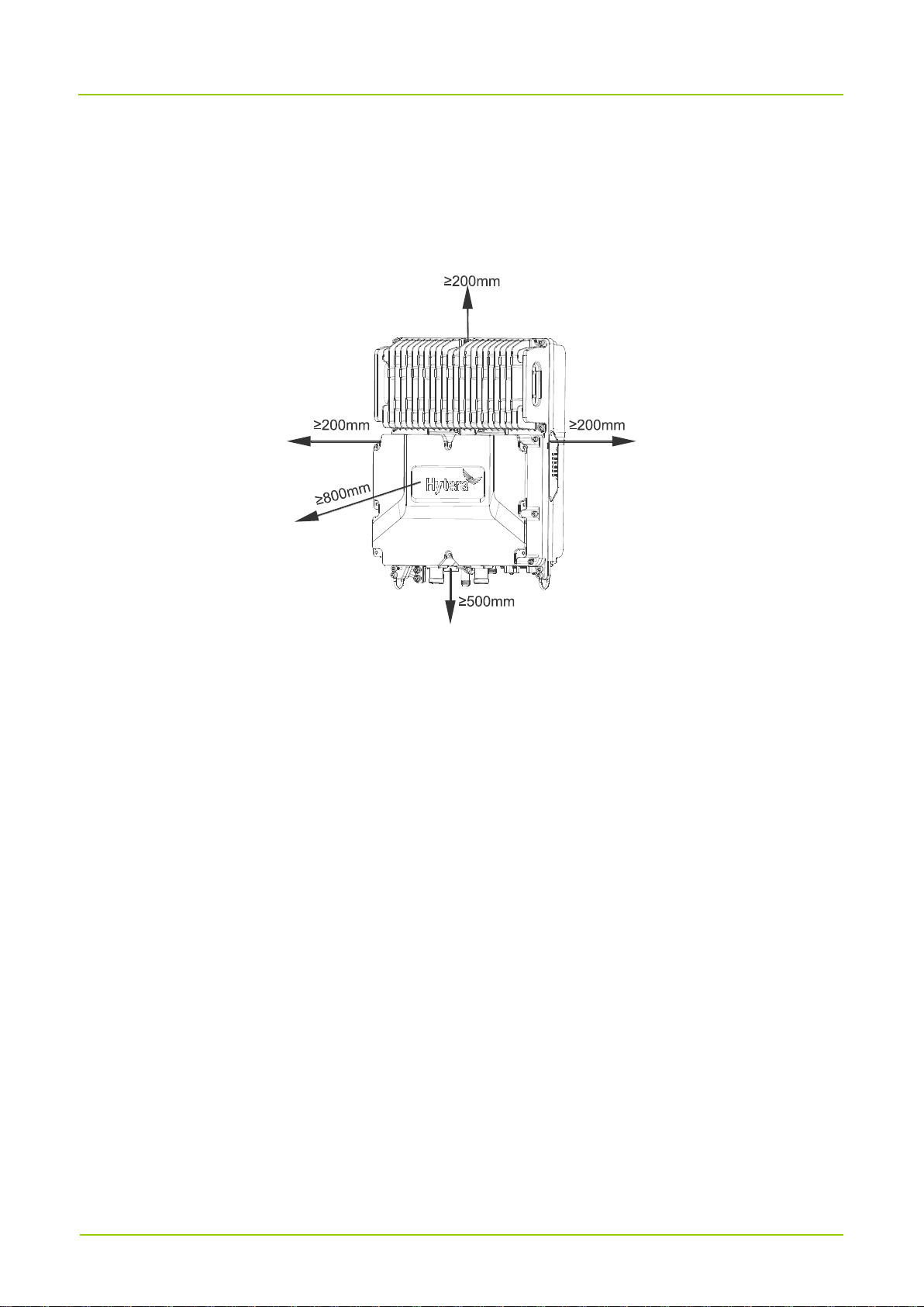
Space Requirements
Keep a space of at least 200 mm above the RRU.
Keep a space of at least 500 mm below the RRU.
Keep a space of at least 200 mm at the left and right sides of the RRU.
Keep a space of at least 800 mm in front of the RRU.
Install the RRU vertically at the correct position.
Grounding Requirements
Be sure to ground the equipment before installing it; disconnect the ground wire finally when removing
the equipment.
Do not destroy the grounding conductor.
Do not operate the equipment when the grounding conductor is not installed.
Connect the equipment to the protection ground permanently. Before operating the equipment, check
its electrical connection and make sure that the equipment has been grounded reliably.
Page 16
User Guide 10
4.3.2 Instruments and Tools
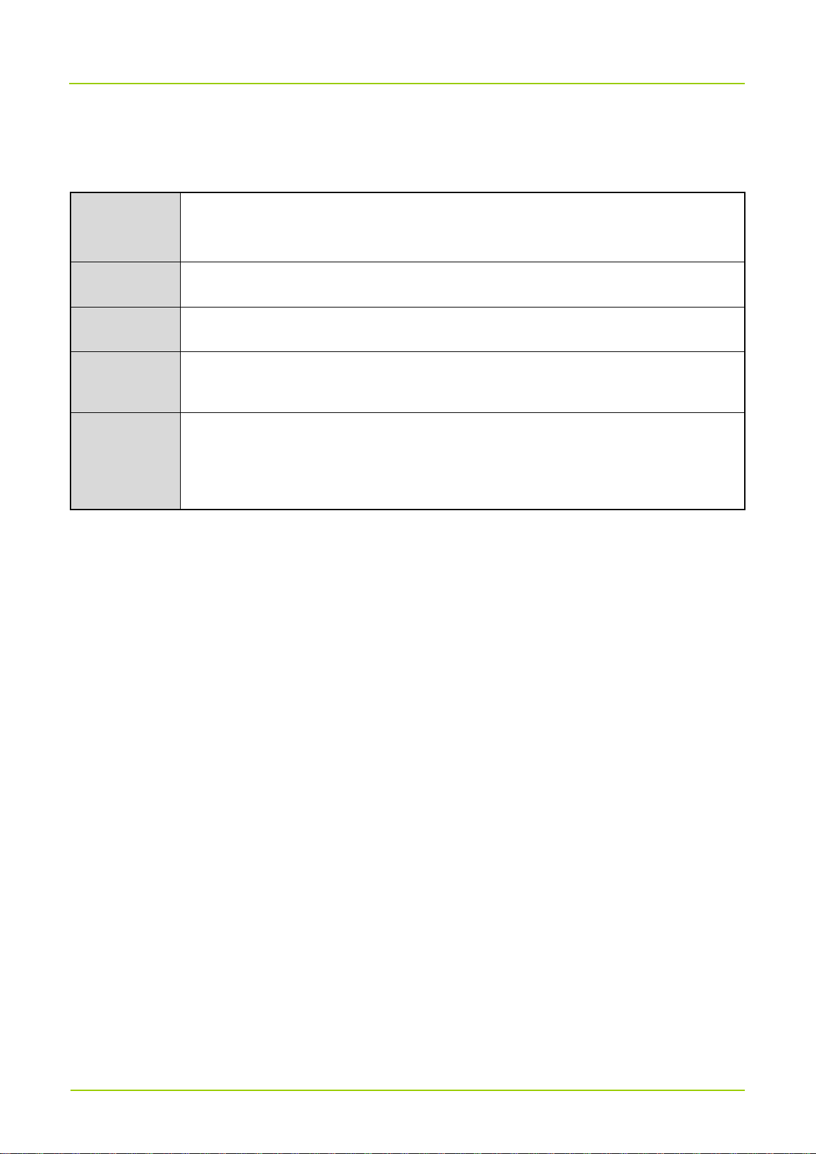
Prepare the following instruments and tools before the installation:
Conventional
tools
Phillips screwdriver, slot type screwdriver, adjustable spanner, inner hexagon spanner,
cross torque screwdriver, combination wrench, rubber hammer, and torque sleeve
Protective
tools
Antistatic wrist strap, safety belt, safety helmet, safety rope, antiskid gloves
Cable making
tools
Cable peeler, crimping pliers, wire nippers
Measurement
instruments
and tools
Multimeter, tape, level ruler
Auxiliary
tools
Fixed pulley, step ladder, marker, hammer drill, insulation tape, cable tie
(anti-ultraviolet cable tie), label, screw assembly, expansion screw assembly, tool
knife, heat gun, waterproof tape
4.3.3 Materials
Unpack for inspection according to the equipment list prior to installation, and make sure that the materials
are complete and intact.
4.4 Installing the Device
Pole-mounted installation and suspended installation can be adopted for the RRU. The user can
independently determine the mounting type of the RRU according to the actual requirement.
4.4.1 Mounting Kits
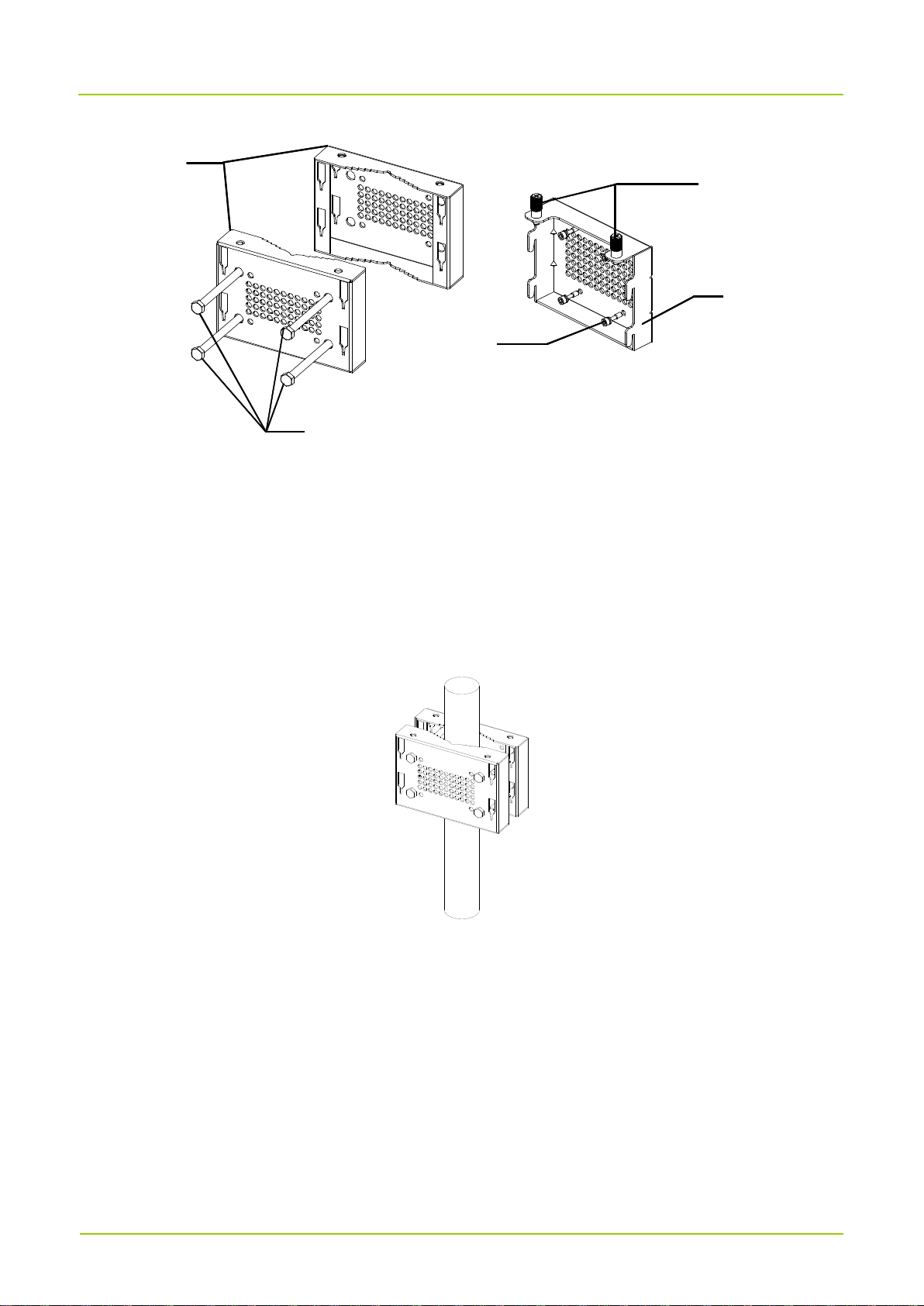
Mounting kits include the hanging part, backboard, lock catch, and M6 screw, as shown below.
Page 17
User Guide
11
Hanging
part
Screw
stem
Captive screw
M6 screw
Backboard
4.4.2 Installing the RRU
Pole-mounted installation
1. Mark the position of the RRU mounting kit on the pole.
2. Insert the pole into two hanging parts, insert the four screw stems into the through holes of hanging
parts, and use a torque wrench to tighten four nuts to make them clamp the hanging parts onto the
pole body, as shown below.
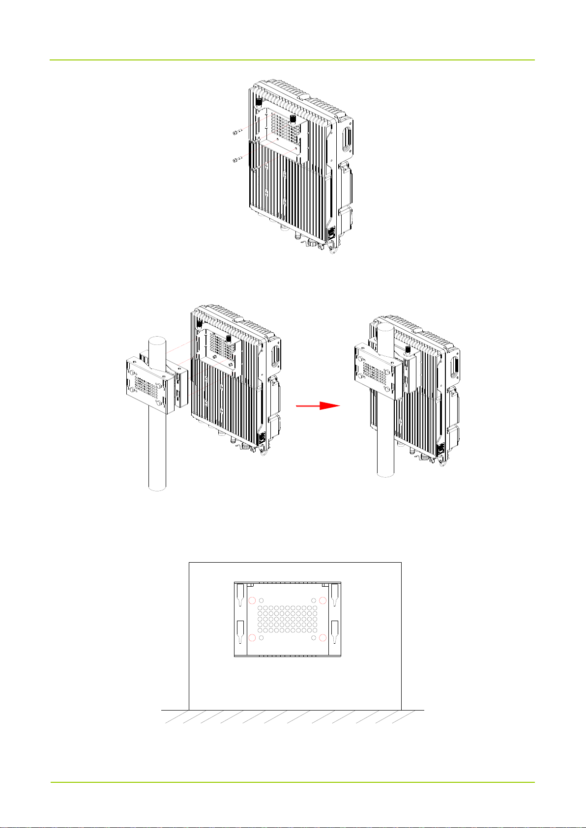
3. Use four M6 screws to lock the RRU backboard onto the RRU cavity back, as shown below.
Page 18
User Guide 12
4. Insert the RRU backboard into the slot of the hanging part, and tighten the captive screws on the RRU
backboard, as shown below.
Suspended installation
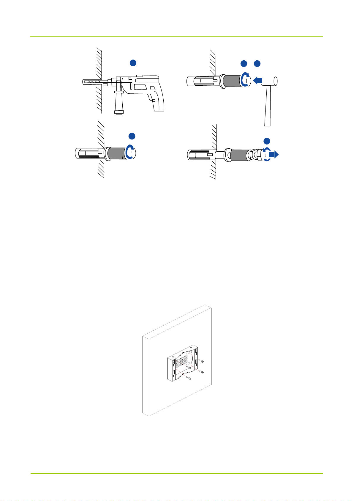
1. Make the hanging parts cling to the wall, use a level ruler to level the installation position, and use a
marker to mark the locating points, as shown below.
2. Drill holes at the locating points, and install the expansion bolts, as shown below.
Page 19
User Guide
13
1
4
5
2 3
a. Use a hammer drill to drill a hole on the vertical wall at the locating point.
b. Tighten the expansion bolt slightly, and place it in the hole vertically.
c. Use a rubber hammer to knock the expansion bolt till the expansion tube enters the hole
completely.
d. Slightly tighten the expansion bolt clockwise.
e. Loosen the expansion bolt anticlockwise, and take out the bolt, spring washer, plastic tube, and flat
gasket in turn.
3. Use the expansion bolt, spring washer and flat gasket to fix the hanging part to the locating hole, and
tighten the expansion bolt, as shown below:
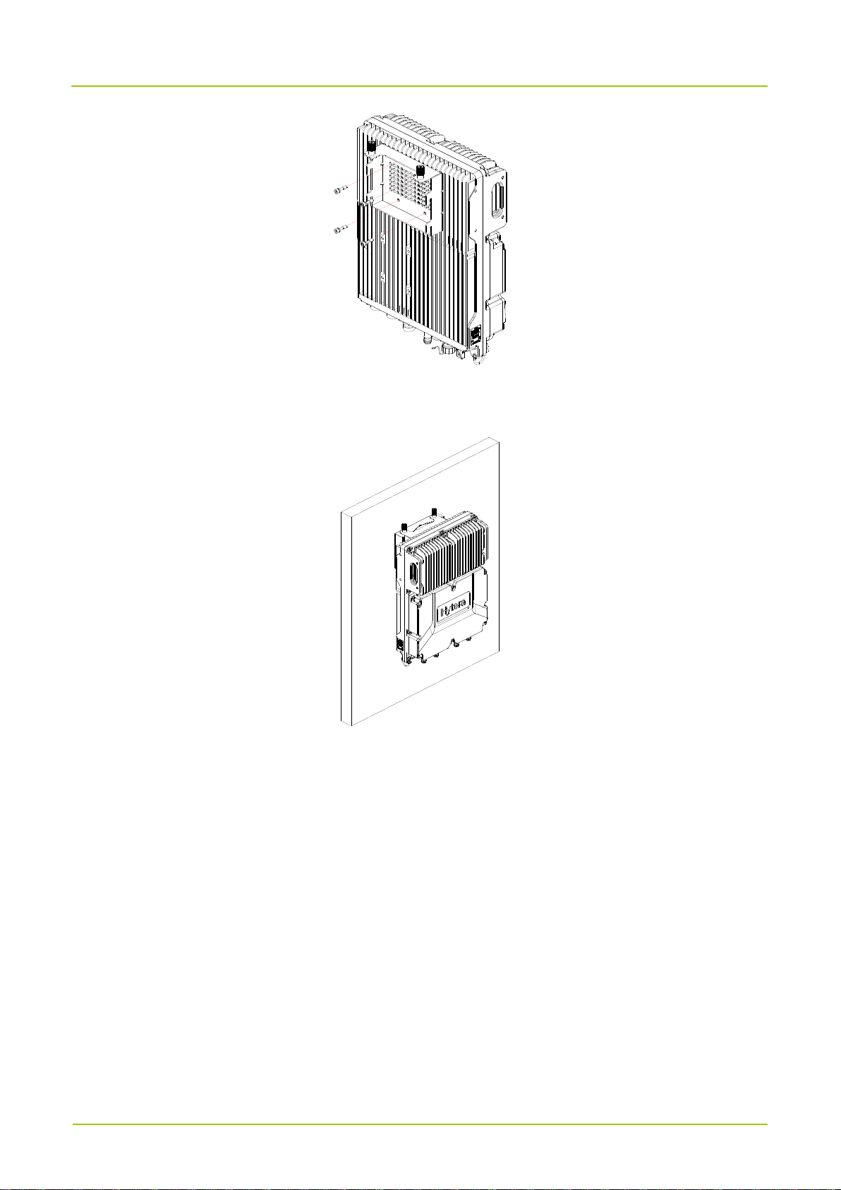
4. Use four M6 screws to lock the RRU backboard onto the RRU cavity back, as shown below.
Page 20
User Guide 14
5. Insert the RRU backboard into the slot of the hanging part, and tighten the captive screws on the RRU
backboard, as shown below.
4.5 Installing Cables
4.5.1 Cabling Requirements
Lay cables according to the related cabling requirements to prevent inter-signal interference.
Safety requirements
Avoid sharp objects or wall burrs as laying out cables. Use bushings to protect cables when they
cannot be avoided.
Stay away from the heat source as laying out cables, or add thermal insulation materials between the
cables and the heat source.
Binding requirements
Bind the cables of the same type together.
Page 21

User Guide
15
The bound cables should be kept close to each other and look straight and tidy, without sheath
damage.
The cable ties should face the same direction; the cable ties at the same position should be at the
same level.
After cables are installed, make sure to stick labels at two ends, intermediate connection positions,
and turning points of cables.
Lay out different types of cables separately. Prevent laid cables from twisting or crossing each other.
Power cord laying requirements
The power cord laying positions should comply with the engineering design drawing requirements.
If the power cord length is not enough during laying, replace the power cord. Do not make joint or
welding spot along the power cord.
Avoid circling or twisting when laying the power cord.
PGND cable laying requirements
Do not lead in the PGND cable from the outdoor overhead layer. It must be buried underground in the
whole course or routed indoors.
Do not bind the PGND cable and signal wire together or make them intertwined, and keep a distance
between them to avoid mutual interference.
All the accessible conductive metal parts in the device enclosure must be connected to the protection
ground terminal reliably.
Fiber laying requirements
Do not bind the fiber at the fiber bending position.
Do not pull the fiber forcefully or use a foot or other heavy objects to press the fiber, and prevent the
fiber from coming into contact with sharp objects, lest the fiber would be damaged.
When routing optical fibers, wind excess fibers on a special device, e.g., a fiber reel.
For the optical fiber jumper, the fiber must be bound with cable ties. If the fibers need to be fixed on a
cabinet or device, use cable ties for the optical fiber. Ensure that the fibers can be pulled freely in the
cable ties but cannot be bent to form a right angle.
Use uniform force when winding fibers. Do not force to bend fibers lest they would be damaged.
Be sure to put on a dust cap when the fiber connector is not in use.
Page 22
User Guide 16
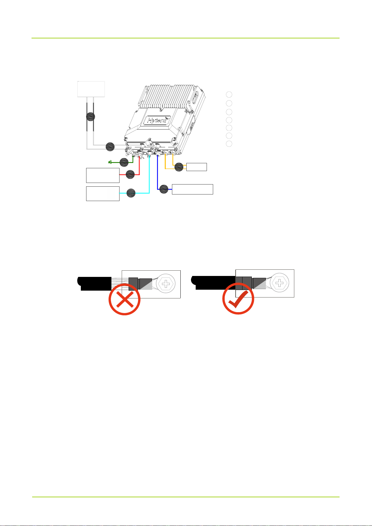
4.5.2 Cable Connection Diagram
The figure below shows the RRU cable connection diagram.
Antenna
External
GNSS or
Wi-Fi device
External
BBU
1
2
3
4
5
6
7
1
RF jumper
PGND cable
power cord
GNSS jumper or RF jumper
Monitoring cable
CPRI fiber line
Feed line
2
3
4
5
6
7
power supply
monitoring device
4.5.3 Installing PGND Cable
1. Cut a proper length of cable to make a RRU PGND cable according to the actual routing path, and
install an OT terminal at each end of the cable.
The metal wire cannot be exposed when the PGND cable is prepared on the field, as shown below.
2. Connect the OT terminal of the RRU PGND cable to the grounding port at the RRU bottom, and the
OT terminal at the other end to the external grounding bar.
3. Stick a label to the installed cables.
Page 23
User Guide
17
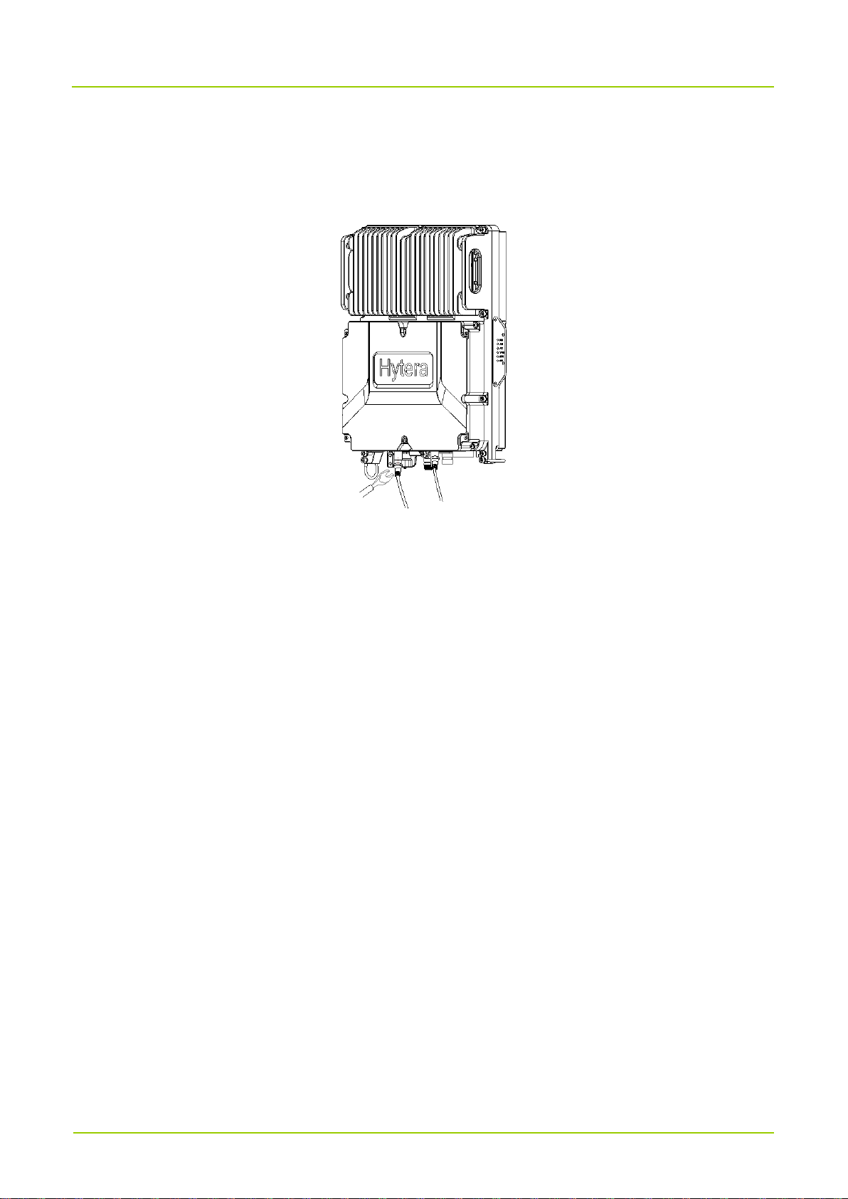
4.5.4 Installing RF Jumper
1. Connect the DIN connector to the antenna interface of the RRU, and use a torque wrench to fasten the
interface, as shown below:
2. Connect the other end of the RRU RF jumper to the feeder end of antenna.
3. Take waterproof measures for the connection port of the RRU RF jumper.
a. Wind three layers of waterproof tapes. Wind to the connector top from 50 mm at the bottom of the
RF jumper connector. First wind layer by layer from bottom up, then wind layer by layer from top
down, and finally wind layer by layer from bottom up. Cut off the tape after the three layers are
wound. After each layer is wound, use a hand to pinch the tape at the bottom to ensure waterproof
effect.
b. Wind PVC insulation tape by three layers. Wind to the connector top from 30 mm at the lower part
of waterproof tape. First wind layer by layer from bottom up, then wind layer by layer from top down,
and finally wind layer by layer from bottom up. Cut off the tape after the three layers are wound.
After each layer is wound, use a hand to pinch the tape at the bottom to ensure waterproof effect.
c. Bind a cable tie at 3 mm‒5 mm from the end on the PVC insulation tape to prevent tape aging.
4. Check the dust cap of the antenna joint, and take waterproof measures for the dust cap by referring to
the previous step.
5. Lay cables according to the specifications, and bind and fix them with cable ties.
6. Stick a label to the installed cables.
Page 24
User Guide 18
4.5.5 Installing RRU Power Cord
1. Connect the connector at one end of the RRU power cord to the RRU power interface, and the
connector at the other end to the corresponding connection position of the external power supply
equipment.
2. Lay cables according to the specifications, and bind and fix them with cable ties.
3. Stick a label to the installed cables.
4.5.6 Installing CPRI Fiber
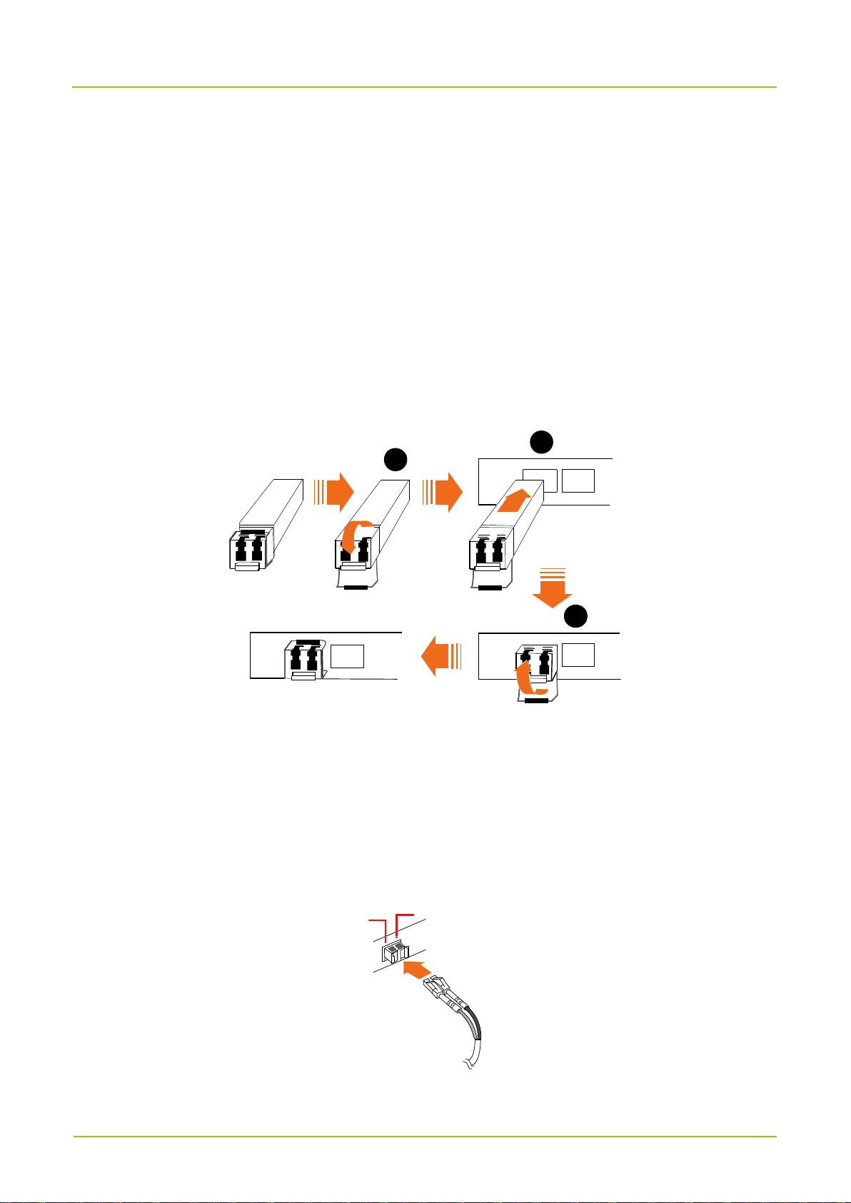
The CPRI fiber is used to connect the BBU and RRU and transmit CPRI signal.
1. Install an optical module on the RRU, as shown below.
RX
TX
RI0 CPRI1
TX
RX
RX
TX
TX
RX
RX
TX
RX
TX
CPRI1
CPRI1
1
2
3
a. Fold down the suspension link of optical module.
b. Insert the optical module into the optical interface.
c. Fold up the suspension link of optical module.
2. Connect the pigtail of CPRI fiber to the optical module at the RRU side, and the other end to the optical
module at the BBU side. The following figure shows the diagram of inserting the CPRI fiber into the
optical module.
TX
RX
Page 25

User Guide
19
3. Lay cables according to the specifications, and bind and fix them with cable ties.
4. Stick a label to the installed cables.
4.5.7 Installing Monitoring Cable
1. Remove the dust cap from the RET interface of the RRU.
2. Connect the connector at one end of the RRU monitoring cable to the RET interface of the RRU, and
the connector at the other end to the external monitoring device.
3. Lay cables according to the specifications, and bind and fix them with cable ties.
4. Stick a label to the installed cables.
4.5.8 Installing GNSS Jumper
1. Remove the dust cap from the GNSS interface of the RRU.
2. Install the GNSS jumper.
➢ When installing the GNSS jumper, connect the connector at one end of the GNSS jumper to the
GNSS interface, and the connector at the other end to the GNSS lightning arrester interface.
➢ When installing the, connect the connector to the GNSS interface.
3. Lay cables according to the specifications, and bind and fix them with cable ties.
4. Stick a label to the installed cables.
4.6 Installation and Power-on Check
4.6.1 Installation Check
Check the installation result according to the table below.
No.
Item
1
The device installation position must strictly comply with the design drawing requirements
and installation space requirements, and a maintenance space must be reserved.
2
The RRU is securely installed.
3
A dust cap is installed at the RF port without RF cable installed, and waterproof measures
are taken for the dust cap.
4
Whole sections of materials must be adopted for all the power cords and PGND cables,
Page 26
User Guide 20
No.
Item
without short circuit and reverse connection; no wires are damaged or broken.
5
Power cords and ground wires should be bound separately from other cables.
6
The connectors of all the cables must be intact and connected firmly and reliably; the cables
are not damaged or broken.
7
The labels are correct, clear and complete; the labels at two ends of various cables, feeders
and jumpers are correct.
4.6.2 Power-on Check
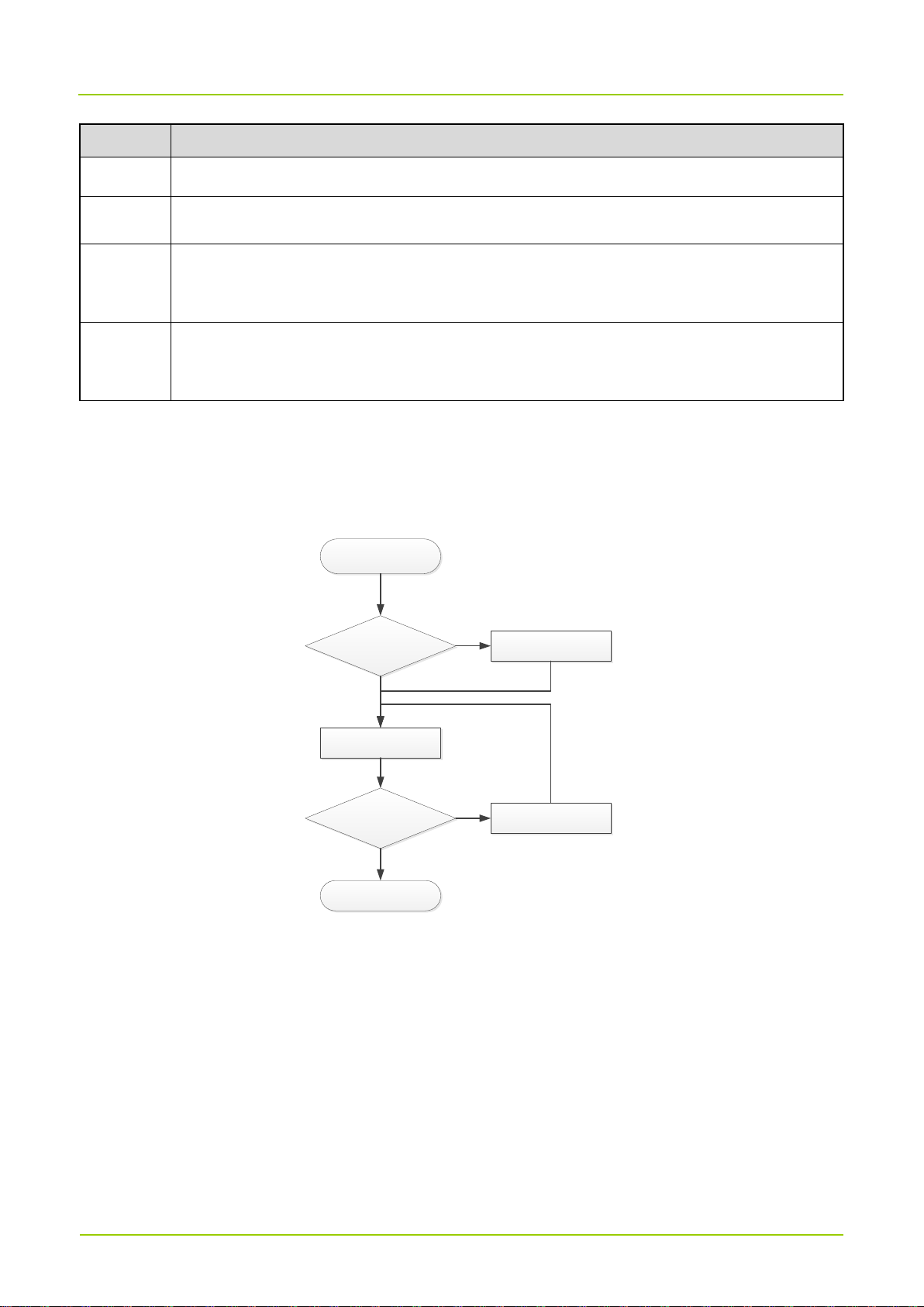
The figure below shows the RRU power-on check flow.
Start
Check whether the
cable connection is
correct
Troubleshoot faults
Power on the RRU
Check whether the
RRU indicator status is
normal
End
Power off the RRU and
troubleshoot faults
Yes
No
No
Yes
Normal statuses of the RRU indicators: The RUN indicator blinks in green, and the ALM indicator is steady
off.
Page 27

User Guide
21
5. Operation and Maintenance
5.1 Powering On RRU
Requirement
The RRU hardware and cables have been installed.
The supply voltage of the RRU power input port is in the range of -38.4 V to -60 V DC.
Procedure
1. Set the corresponding air switch on the matched power equipment of the RRU to "ON", and power
on the RRU.
2. Check the indicator status of the RRU device several minutes later.
3. Perform operation of the next step according to the indicator status.
➢ The power-on process ends if the RRU operates normally.
➢ If the RRU fails, set the corresponding air switch on the matched power equipment of the RRU to
"OFF", eliminate the failure, and continue with steps 1‒3.
5.2 Powering Off RRU
Set the corresponding air switch on the matched power equipment of the RRU to "OFF".
Page 28

User Guide 22
6. Troubleshooting
Symptom
Cause Analysis
Solution
The unit cannot be
powered on.
The power cord is not connected or contact
with the socket is too loose.
Connect the power cord properly
and ensure good contact.
The green RUN
indicator is steady
on.
There is power input, but the module fails.
Eliminate the module failure or
directly replace the module.
The green RUN
indicator is steady
off.
There is no power input, or the module fails.
Check whether the power cord is
connected normally, or eliminate
the module failure. Directly
replace the module when
necessary.
The red ALM
indicator is steady
on.
There is an alarm, and the module fails.
Directly replace the module.
The red ALM
indicator blinks.
The alarm arises from the related interface
failure.
Check the related interface.
The red VSWR
indicator blinks
quickly.
One or more ports report the VSWR alarm
during startup of the RRU.
Check whether the antenna
feeder system is connected
normally.
The red VSWR
indicator blinks
slowly.
One or multiple channels are abnormal after
the cell is established.
Check whether the antenna
feeder system is connected
normally.
The SFP indicator is
steady off.
The CPRI fiber link fails.
Check whether the fiber
connection is normal and whether
the optical module is inserted
properly.
If the problem persists, please contact Hytera.
Page 29

User Guide
23
7. Care and Cleaning
To guarantee optimal performance and a long service life of the product, please follow the tips below to
perform routine maintenance and cleaning work better for it.
注意
Caution
Be sure to power down the product before cleaning it.
Maintenance
When an external interface will not be used, install a waterproof rubber plug at the external interface,
lest the waterproof and dustproof performance of the product would be affected.
Do not use a hard object to pierce, knock or scratch the product; do not throw the product or exert
intensity vibration on it.
Do not store the product in an environment with substances corroding electronic circuits.
Keep the product dry.
Do not keep the product in a place at a too high temperature. High temperature will shorten the service
life of electronic device, destroy the battery, and deform or melt some plastic parts.
Do not keep the product in a place at a too low temperature. When the device temperature rises to the
normal temperature, moisture will be generated inside to damage the circuit board.
Cleaning
Clean up the dust on the product surface and charging pole piece with a clean and dry lint-free cloth or
a brush regularly.
If the product casing gets dirty, use neutral detergent and non-woven fabric to clean it. Do not use
chemical agents such as stain removers, alcohol, sprays or oil preparations that may damage the product
surface and casing. After cleaning, make sure that the product becomes dry thoroughly before use.
Page 30
User Guide 24
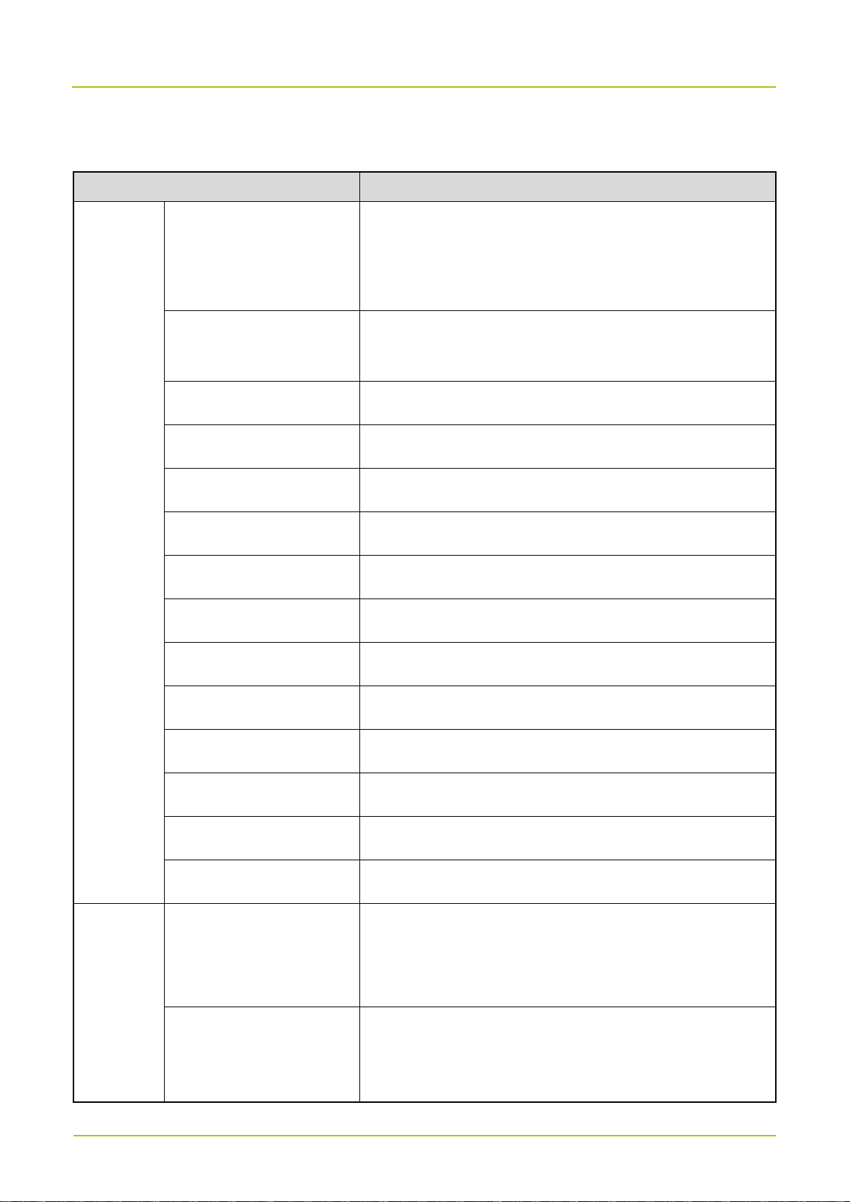
8. Technical Specifications
Item
Specification
General
Frequency range
Band26
RX: 814MHz to 849MHz
TX: 859MHz to 894MHz
Transmission distance
Single cascade: >10km
Multi-level cascade: >40km
Operating voltage
-48V DC
Extreme operating voltage
-38.4V to -60V DC
Antenna configuration
2T2R
Operating Bandwidth
35MHz
Carrier bandwidth
1.4MHz/3MHz/5MHz/10MHz/15MHz
Rated power
40W
Operating temperature
-40°C to +55°C, can start at -40°C
Storage temperature
-40°C to +85°C
Operating humidity
5% to 100% RH
Dustproof and waterproof
IP66
Volume
<23L
Weight
26.5kg
Receiver
RX sensitivity
1.4MHz: ≤-110dBm
3MHz: ≤-106.5dBm
5MHz/10MHz/15MHz: ≤-105dBm
In-channel selectivity
1.4MHz: ≥19.9dB (wanted signal: -106.9dBm; unwanted
signal: -87dBm)
3MHz: ≥18.1dB (wanted signal: -102.1dBm; unwanted
Page 31
User Guide
Error! Use the Home tab to apply 标题 1 to
the text that you want to appear here. 25
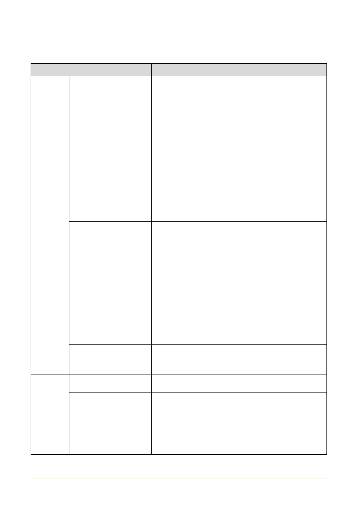
Item
Specification
signal: -84dBm)
5MHz: ≥19dB (wanted signal: -100dBm; unwanted
signal: -81dBm)
10MHz/15MHz: ≥21.5dB (wanted signal: -98.5dBm;
unwanted signal: -77dBm)
Adjacent channel
selectivity
1.4MHz: ≥43.8dB (wanted signal: +6dB; unwanted
signal: -49dBm)
3MHz: ≥43dB (wanted signal: -+3dB; unwanted signal:
-49dBm)
5MHz/10MHz/15MHz: ≥43.5dB (wanted signal: +1dB;
unwanted signal: -49dBm)
Blocking
1.4MHz: ≤-109dBm (E-UTRA unwanted signal: -43dBm;
CW wanted signal: -15dBm)
3MHz: ≤-105.5dBm (E-UTRA unwanted signal: -43dBm;
CW wanted signal: -15dBm)
5MHz/10MHz/15MHz: ≤-104dBm (E-UTRA unwanted
signal: -43dBm; CW wanted signal: -15dBm)
Intermodulation response
rejection
1.4MHz: ≤-109dBm (-52dBm)
3MHz: ≤-105.5dBm (-52dBm)
5MHz/10MHz/15MHz: ≤-104dBm (-52dBm)
Spurious emission
≤-57dBm/100kHz (9kHz to 1GHz
)
≤-47dBm/MHz (1GHz to 12.75GHz
)
Transmitter
Output power
2x40W
Transmit vector error
<4.5%@64QAM
<12.5%@16QAM
<17.5%@QPSK
Transmit frequency error
±
0.05ppm
User Guide 26
Page 32

Item
Specification
Occupied bandwidth
1.4 MHz/3MHz/5MHz/10MHz/15MHz
Adjacent Channel Power
Ratio
≤-50dB
Out-of-band spurious
emission
≤-36dBm/1kHz (9kHz‒150kHz)
≤-36dBm/10kHz (150kHz‒30MHz)
≤-36dBm/100kHz (30MHz‒1GHz)
≤-30dBm/1MHz (1GHz‒12.75GHz)
Page 33
User Guide
Error! Use the Home tab to apply 标题 1 to
the text that you want to appear here. 27
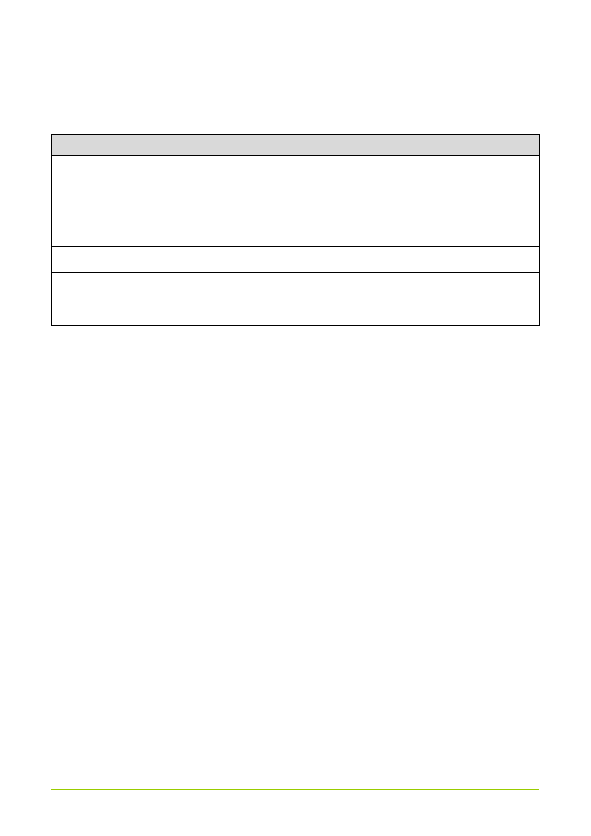
9. Abbreviations
Abbreviation
Full Name
B
BBU
Base Band Unit
G
GNSS
Global Navigation Satellite System
R
RRU
Radio Remote Unit
 Loading...