

Page 1

Preface
Thank you for purchasing Hytera DMR Repeater. Combination of ergonomic design,
versatile digital functions and remarkable quality would refresh your experience and
enable you to be responsive to emergent situations.
To derive optimum performancefrom your product, please read this manual and the
supplied Safety Information Booklet carefully before use.
The manual is applicable to the following model:
RD98X
Page 2

Instructional Icons
The following icons are available through this manual:
Caution: indicates situations that could cause damage to your product.
Note: indicates tips that can help you make better use of your product.
*: indicates functions available in later version.
Copyright Information
Hytera and HYT are trademarks or registered trademarks of Hytera Communications Co.,
Ltd. (“Hytera”) in PRC and/or other countries or areas. Hytera retains the ownership of its
trademarks and product names.All other trademarks and/or product names that may be
used in this manual are properties of their respective owners.
The Hytera product described in this manual may include Hytera computer programs
stored in memory or other media. Laws in PRC and/or other countries or areas protect the
exclusive rights of Hytera with respect to its computer programs. The purchase of this
product shall not be deemed to grant, either directly or by implication, any rights to the
purchaser regarding Hytera computer programs. Any Hytera computer programs may not
be copied, modified, distributed, decompiled, or reverse-engineered in any manner
without the prior written consent of Hytera.
The AMBE+2TMvoice coding technology embodied in this product is protected by
intellectual property rights including patent rights, copyrights and trade secrets of Digital
Voice Systems, Inc.
This voice coding technology is licensed solely for use within this product. The user of this
technology is explicitly prohibited from attempting to decompile, reverse engineer, or
disassemble the Object Code or in any other way convert the Object Code into a human
1
Page 3

readable form.
U.S.PatentNumbers:#6,912,495B2,#6,199,037B1,#5,870,405,#5,826,222,#5,754,974,#5,701,390,
#5,715,365,#5,649,050,#5,630,011,#5,581,656,#5,517,511,#5,491,772,#5,247,579,#5,226,084and
#5,195,166.
Disclaimer
Hytera endeavors to achieve the accuracy and completeness of this manual, but no warranty of
accuracy or reliability is given. All the specifications and designs are subject to change without
notice due to continuous technology development. No part of this manual may be copied,
modified, translated, or distributed in any manner without the express written permission of
Hytera.If you have any suggestions or would like to learn mo redetails, please visit our website at:
http://www.hytera.cn.
● Your radio is designed and tested to comply with a number of national and international
standards and guidelines (listed below) regarding human exposure to radio frequency
electromagnetic energy. This radio complies with the IEEE and ICNIRP exposure limits for
occupational/controlled RF exposure environment at operating duty factors of up to 50%
transmitting and is authorized by the FCC for occupational use only. In terms of measuring
RF energy for compliance with the FCC exposure guidelines, your radio radiates measurable
RF energy only while it is transmitting (during talking), not when it is receiving (listening) or
in standby mode.
● The device complies with SAR and/or RF field strength limits of RSS-102 requirement and
contact information where the user can obtain Canadian information on RF exposure and
compliance.
Your radio complies with the following of RF energy exposure standards and
guidelines
● United States Federal Communications Commission, Code of Federal Regulations; 47CFR
part 2 sub-part J
● American National Standards Institute (ANSI)/Institute of Electrical and Electronic Engineers
(IEEE) C95. 1-1992
● Institute of Electrical and Electronic Engineers (IEEE) C95. 1-1999 Edition
● International Commission on Non-Ionizing Radiation Protection (ICNIRP) 1998
Operational Instructions and Training Guidelines
● To ensure optimal performance and compliance with the occupational/controlled environment
RF energy exposure limits in the above standards and guidelines, users should transmit no
RF Energy Exposure Compliance
2
Page 4
more than 50% of the time and always adhere to the following procedures:
● Gain of antenna must not exceed 6.5dBi.
● Antenna Installation: Install the mobile antenna at least 350 cm away from your body, in
accordance with the requirements of the antenna manufacturer/supplier.
Transmit and Receive
To transmit (talk), push the Push-To-Talk (PTT) key; to receive, release the PTT key.
EU Regulatory Conformance
The equipment is in compliance with the essential requirements and other relevant provisions of
the Directive 1999/5/EC.
Note: The above information is applicable to EU countries only.
FCC Licensing Information
Part 15 Compliance
This equipment has been tested and found to comply with the limits for a Class B digital device,
pursuant to part 15 of the FCC Rules. These limits are designed to provide reasonable protection
against harmful interference in a residential installation. This equipment generates, uses and can
radiate radio frequency energy and, if not installed and used in accordance with the instructions,
may cause harmful interference to radio communications. However, there is no guarantee that
interference will not occur in a particular installation. If this equipment does cause harmful
interference to radio or television reception, which can be determined by turning the equipment off
and on, the user is encouraged to try to correct the interference by one or more of the following
measures:
Reorient or relocate the receiving antenna.
Increase the separation between the equipment and receiver.
Connect the equipment into an outlet on a circuit different from that to which the receiver is
connected.
Consult the dealer or an experienced radio/TV technician for help.
FCC Licensing Requirements
A license from Federal Communications Commission is required prior to use. Your dealer will
program each radio with your authorized frequencies, signaling codes, etc., and will be there to meet
your communications needs as your system expands. Contact your dealer for more information.
3
Page 5

Contents
Checking Items in the Package...........................................................................................5
Product Overview................................................................................................................6
Front Panel...................................................................................................................6
Programmable Keys.....................................................................................................6
Rear Panel....................................................................................................................7
Internal Layout..............................................................................................................8
Installation Guide.................................................................................................................8
Installation Requirements.............................................................................................8
Before Installation.........................................................................................................9
Installation Steps..........................................................................................................9
Installation Diagram....................................................................................................11
After-installation Verification.......................................................................................12
StatusIndication.................................................................................................................12
LCD Icon.....................................................................................................................12
LED Indicator..............................................................................................................13
Basic Operations................................................................................................................14
Turning the Repeater On/Off......................................................................................14
Adjusting Volume........................................................................................................14
Adjusting Power Level................................................................................................14
Backlight.....................................................................................................................14
Locking/Unlocking the Repeater................................................................................15
Menu Navigation................................................................................................................15
Radio Info...................................................................................................................15
Channel Info...............................................................................................................16
Exit..............................................................................................................................16
Alarm Information..............................................................................................................16
OverTemperature Alarm ............................................................................................16
Fan FailureAlarm.......................................................................................................17
VSWRAlarm...............................................................................................................18
Low Forward PowerAlarm.........................................................................................19
Over/Low Voltage Alarm.............................................................................................19
Troubleshooting .................................................................................................................21
Care and Cleaning.............................................................................................................22
OptionalAccessories.........................................................................................................23
4
Page 6
Checking Items in the Package
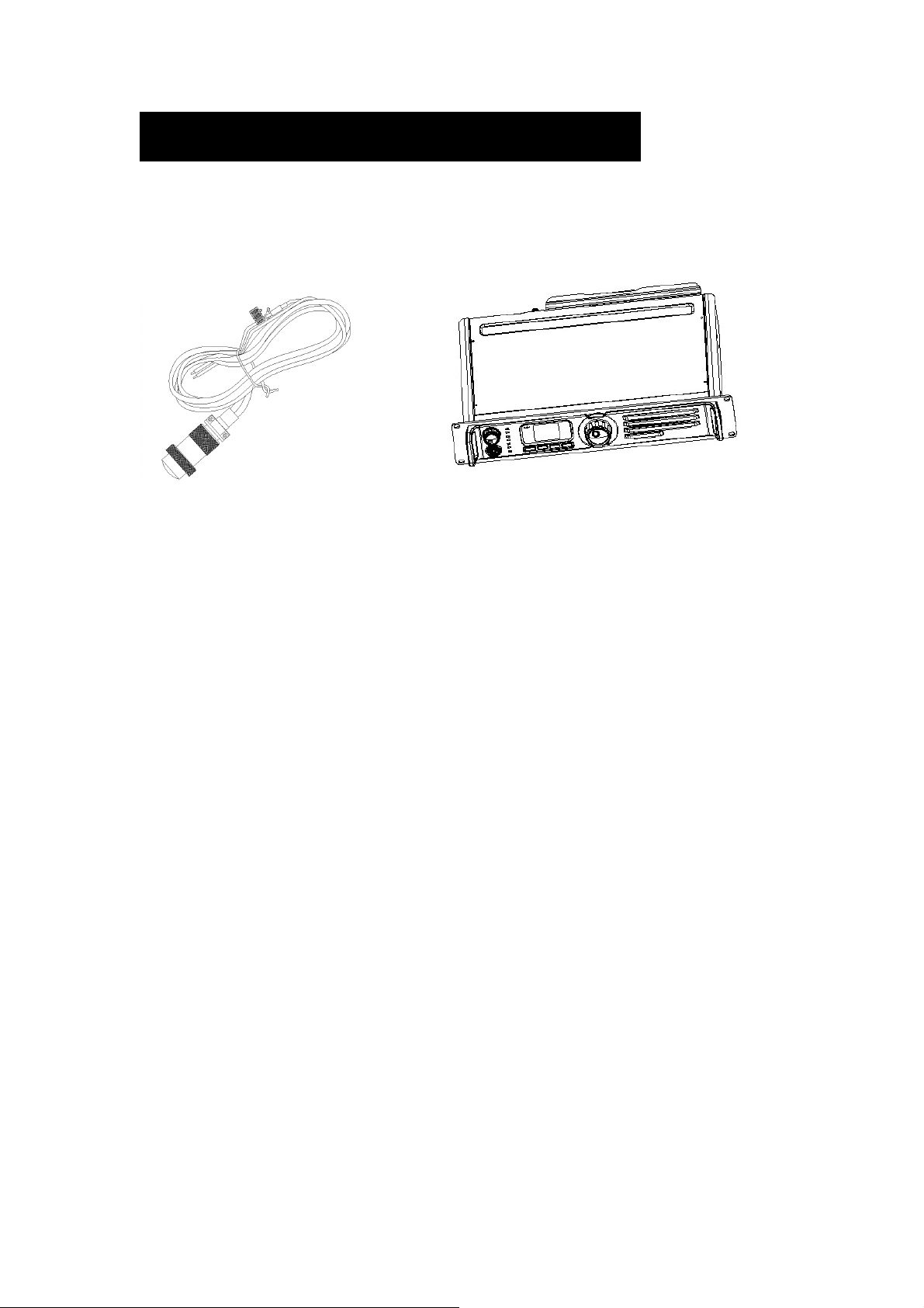
Please unpack carefully and check that all items listed below are received. If any item is
missing or damaged, please contact your dealer.
Power Cord Repeater
Owner’s Manual Safety Information Booklet
5
Page 7
Product Overview
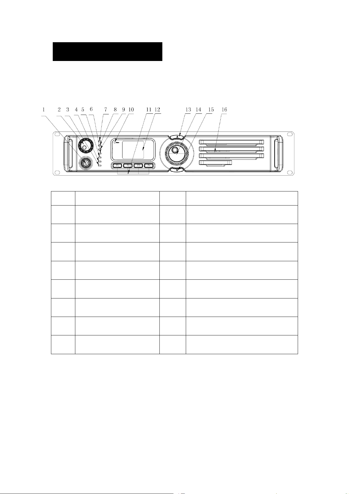
Front Panel
No. Part Name No. Part Name
1 Accessory Jack
○
3 Repeater Mode Indicator
○
5 Slot 2 RX Indicator
○
7 Digital Mode Indicator
○
9 Slot 1 RX Indicator
○
11 Programmable Key *
○
13
○
15
○
Channel Up (CH+) *
Channel Down (CH-) *
Programmable Keys *
2 Volume Control Knob / Power Indicator
○
4 Analog Mode Indicator
○
6 Slot 2 TX Indicator
○
8 Slot 1 TX Indicator
○
10
○
12 LCD Display
○
14
○
16
○
Alarm Indicator
Navigation Knob
Speaker
For enhanced convenience, you can request your dealer to program the keys P1, P2, P3
and P4 as shortcuts to appropriate functions.
6
Page 8
Rear Panel
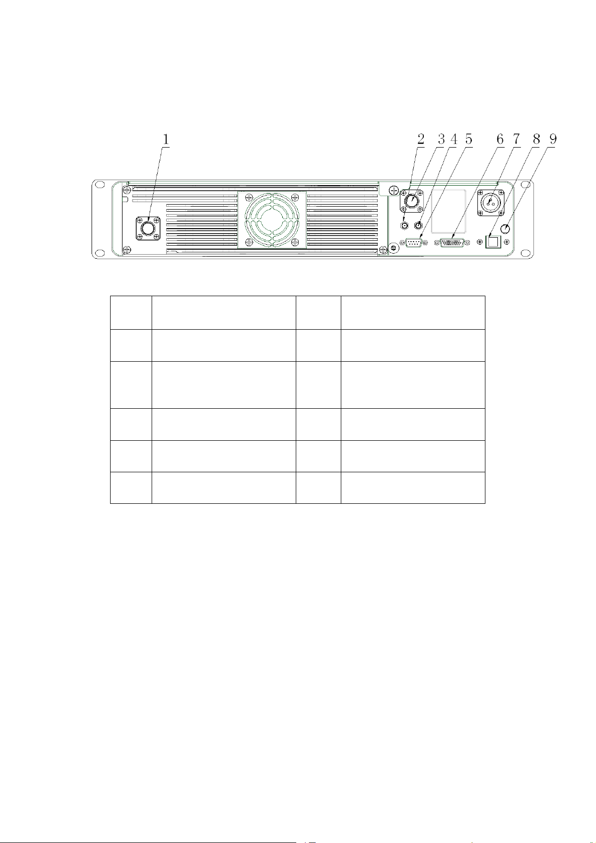
No. Part Name No. Part Name
1 TX Antenna Interface
○
RX/Duplex Antenna
3
○
Interface
5 Monitor/Tuning Interface
○
7 DC Power Interface
○
9 Ground Screw
○
2 Optional Interface 1
○
4 Optional Interface 2
○
6 Accessory Jack
○
8 Ethernet Port *
○
7
Page 9
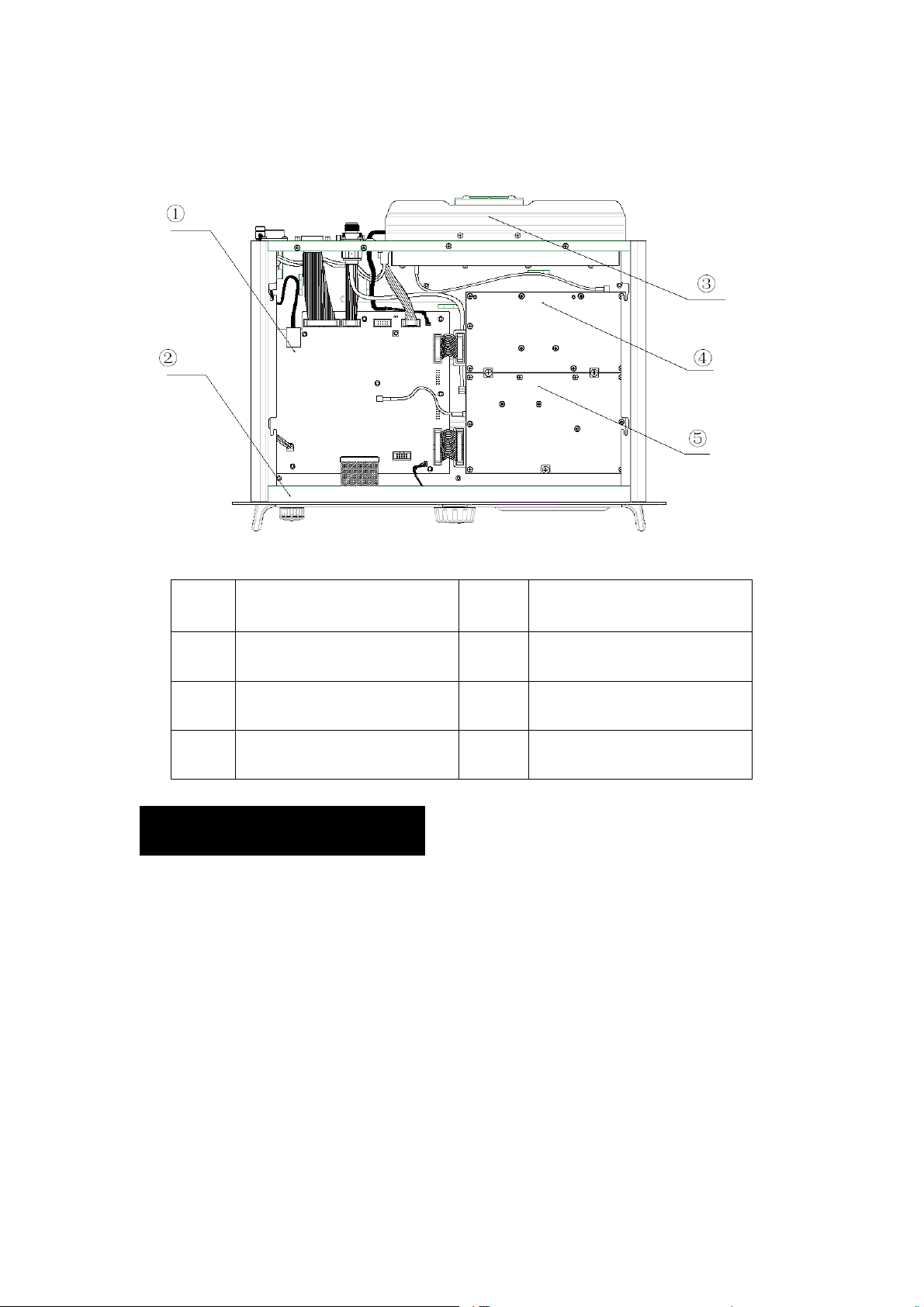
Internal Layout
No. Part Name No. Part Name
1 Baseband Module
○
3 PAModule
○
5 RX Module
○
2 Front Panel
○
4 Excitor Module
○
Installation Guide
Proper installation can ensure optimum performance and reliability of the repeater.
Therefore, be sure to read the following instructions before installation.
Installation Requirements
1. Installation Environment
The repeatermust be installed in a dry and well-ventilated place with ambient temperature
of-30℃~+60℃ and relative humidity of less than 95%.
2. Installation Location
8
Page 10

The repeater can be installed in a rack, bracket and cabinet or on a desk.
3. Installation Tool
Tools required for installing the repeater include a cross head screwdriver, a torx
screwdriver and a spanner.
Note: please refer to Safety Information Booklet for more information.
Before Installation
1. Voltage Check
Please check whether the voltage of DC power or external battery meets the repeater
specifications.
2. Product Check
Please check whether the repeater works properly by observing the 8 LEDs located on
the front panel.
3. Parameter Configuration
When the repeater proves to work normally, configure appropriate parameters according
to your actual requirements.And then you can proceed with on-site installation.
Installation Steps
Install the repeater as follows:
1. Install the repeater at a proper location;
2. Attach all necessary accessories;
3. Ground the repeater through the Ground Screw located on the rear panel.
Note: if the repeater needs to work with a duplexer, you should implement the
following operations before installation.
1. Loosen the three screws on the bracket with a cross head screwdriver.
9
Page 11
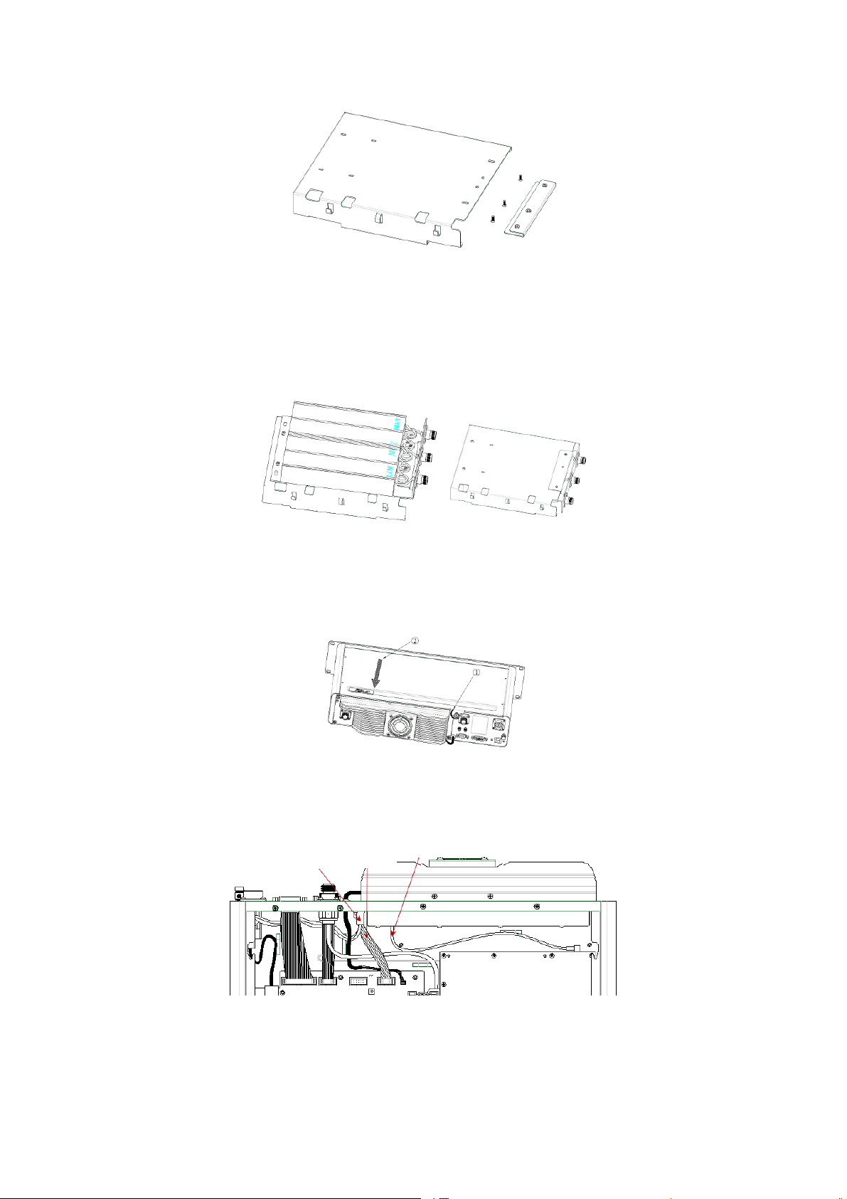
2. Install the duplexer onto the bracket. Be sure to observe the specifications of two
antenna interfaces on the duplexer, to determine which one should be connected to
the transmitter. The interface connecting the transmitter should be close to PA
module to reduce RF loss, as shown below:
3. Loosen the screw at the back of the top cover, and then pull the top cover to remove
it.
4. Loosen the 6 screws locking the PA heat sink, disconnect all power, data and RF
cables, and finally remove the heat sink.
Power Cord Data Cable
RF Cable
5. Connect the RF cable, as shown below.
10
Page 12
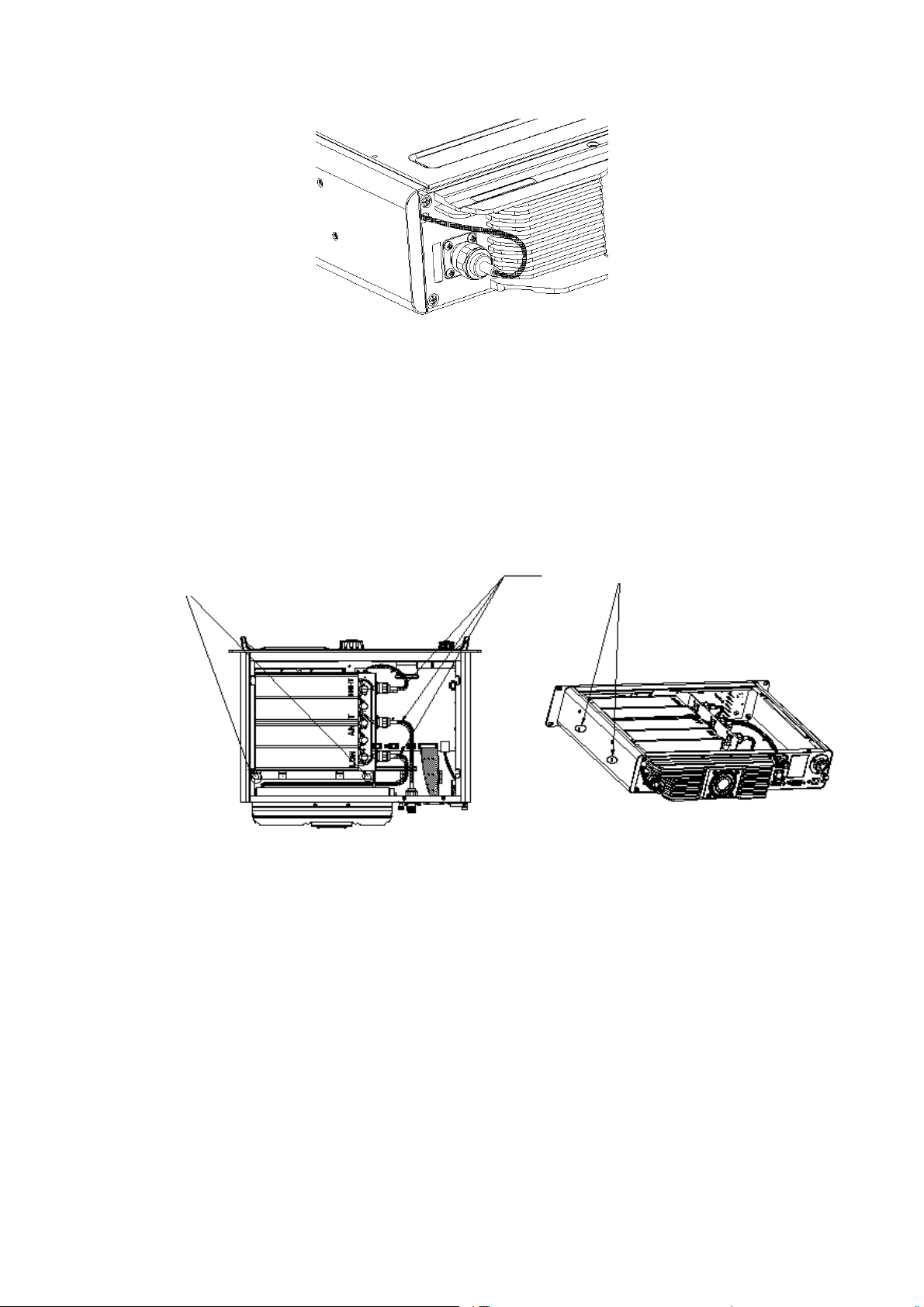
6. After the duplexer is mounted properly, fasten it with the 2 screws inside the housing
and on the side respectively. Then attach the PA heat sink and connect all cables.
Installation Diagram
Screw
RF Cable
Screw
Duplexer with Front Side Facing Upwards
11
Page 13
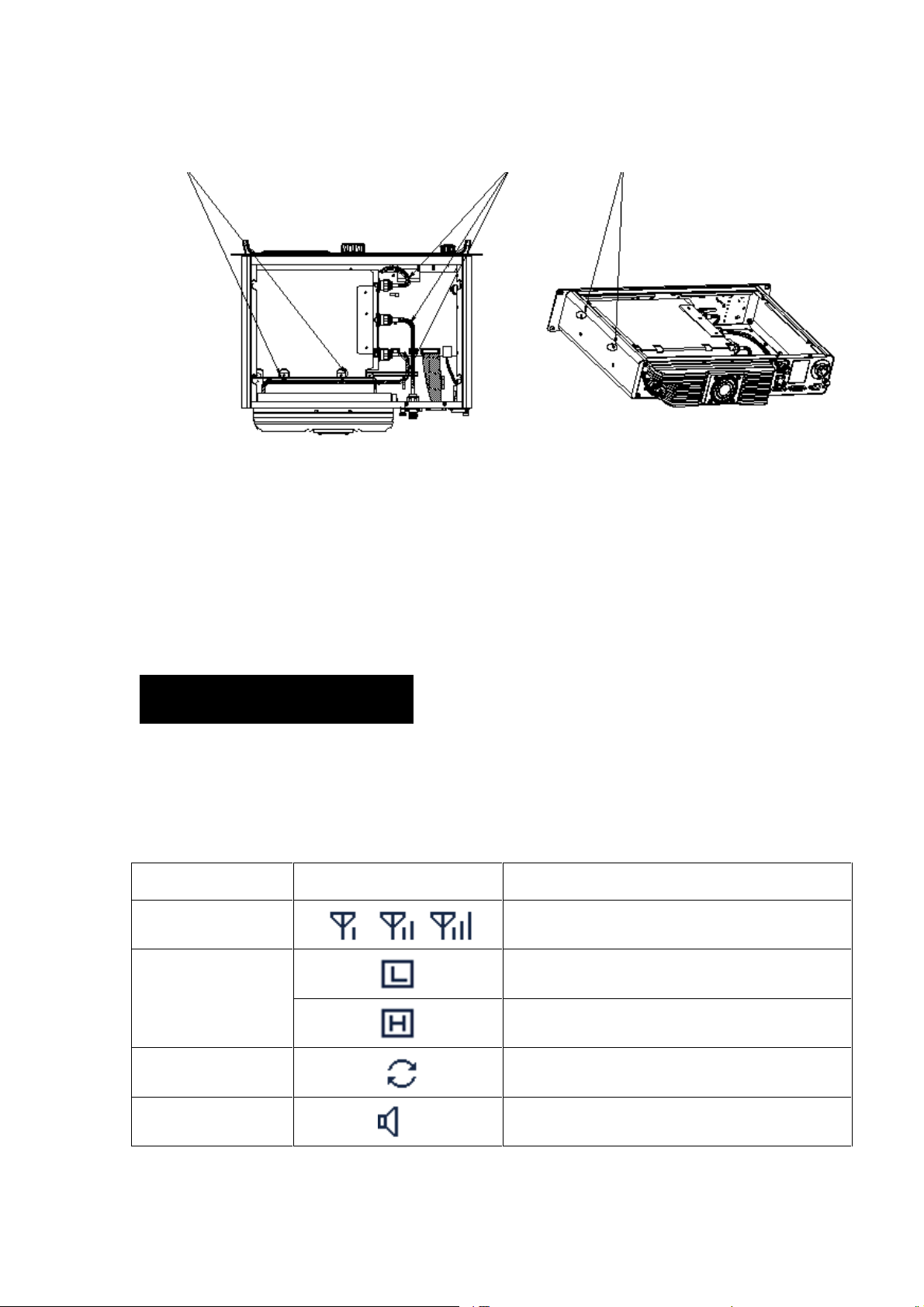
ScrewScrew RF Cable
Duplexer with Front Side Facing Downwards
After-installation Verification
After installation is completed, power it on and verify whether it works properly by
observing the 8 LEDs located on the front panel.
Status Indication
LCD Icon
These icons may appear on LCD. They can help you easily identify the repeater status.
Icon Name Icon Repeater Status
RSSI Indicator More bars indicate better signal strength; *
Low TX power for the current channel;
TX Power Indicator
High TX power for the current channel;
Scan Indicator Scan is in progress; *
Monitor Indicator The feature “Monitor”is active; *
12
Page 14
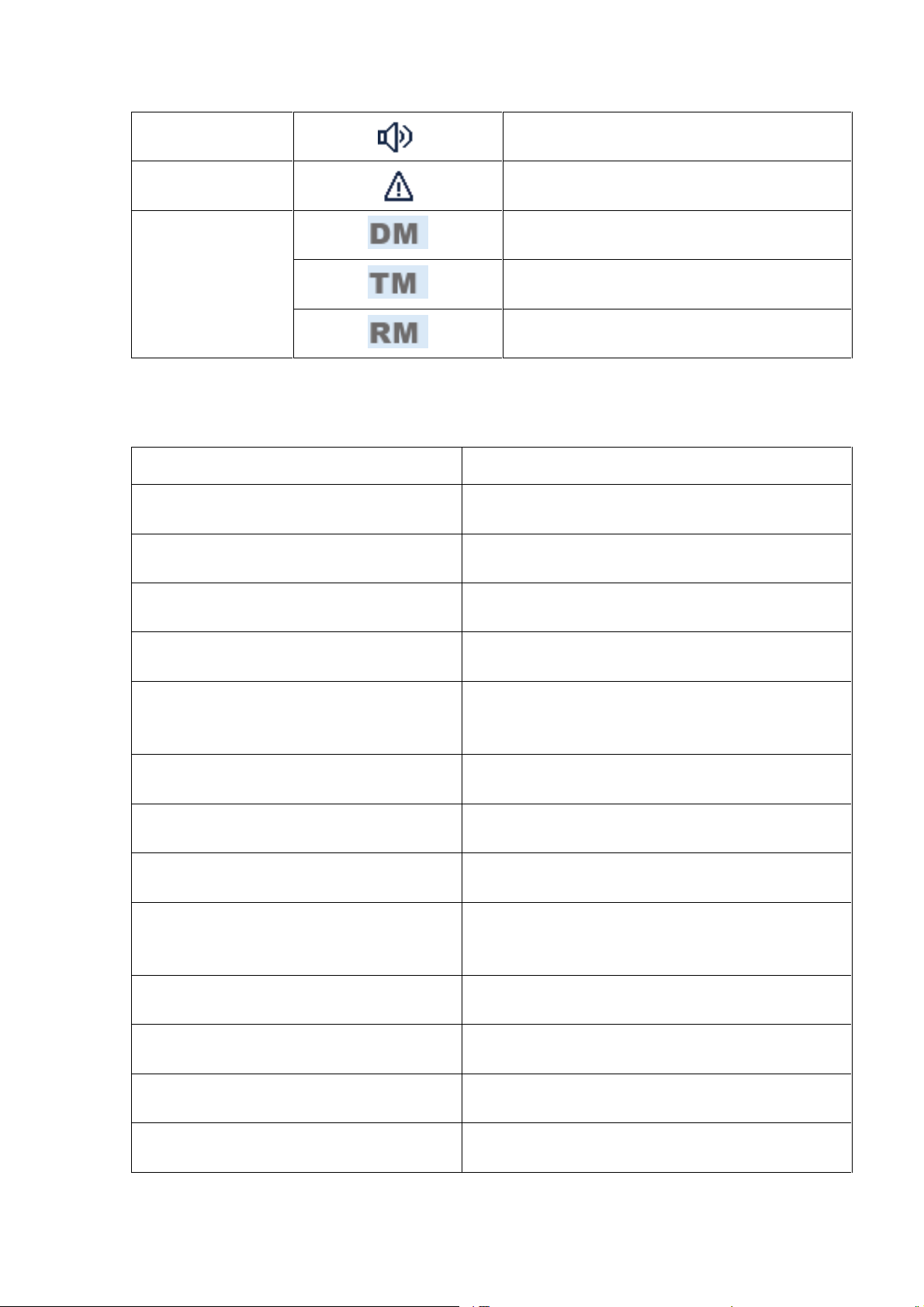
Speaker Indicator The speaker is unmuted; *
Alarm Indicator An alarm message appears; *
The repeater is operating in DMO mode; *
Operation Mode
The repeater is operating in TMO mode; *
Indicator
The repeater is operating in Repeat mode; *
LED Indicator
LED Indicator Repeater Status
Power indicator (○2 ) glows green. Normal power-on
Alarm indicator (○10 ) glows red.
Repeater mode indicator (○3 ) glows green The repeater is operating in Repeat mode
Repeater mode indicator (○3 ) goes out. The repeater is operating in Base mode
Slot 1 TX indicator (○8 ) glows red.
Slot 1 TX indicator (○8 ) flashes red.
Slot 2 TX indicator (○6 ) glows red.
Slot 2 TX indicator (○6 ) flashes red.
Slot 1 RX Indicator (○9 ) glows green.
Slot 1 RX indicator (○9 ) flashes green.
The repeater works abnormally
Repeater is transmitting on an analog channel or on
slot 1
Busy channel lockout * / transmission time-out *
Repeater is transmitting on slot 2
Busy channel lockout * / transmission time-out *
Repeater is receiving on an analog channel or on
slot 1
The feature “Monitor”is enabled *
Slot 2 RX Indicator (○5 ) glows green.
Analog mode indicator (○4 ) glows yellow.
Digital mode indicator (○7 ) glows blue.
Repeater is receiving on slot 2
The repeater is operating inAnalog mode
The repeater is operating in Digital mode
13
Page 15

Basic Operations
Turning the Repeater On/Off
ON:turn on the repeater by connecting a DC power supply to it. During power-up process,
the Power indicator glows green and the LCD shows animation.
OFF: Disconnect the DC power supply.
Adjusting Volume
In analog mode: rotate the Volume Control knob clockwise to increase the volume or
counter-clockwise to decrease the volume.
In digital mode: the speaker is muted, so this knob does not work.
Adjusting Power Level
You may request your dealer to set the TX power to High or Low. High power can extend
repeater coverage, enabling you to communicate with farther terminals. The TX power is
represented by the icon and respectively on the LCD.
Backlight
Activating the backlight can illuminate the LCD and all the front panel keys, so as to
facilitate your operation.
You dealer can set the backlight to operate in any of the following modes:
Timed: either key press or knob operation can activate the backlight. If no foregoing
event occurs within the specified time period, the backlight will go out automatically.
Enable: the backlight remains activated all the time.
Note: When an alarm event occurs, the backlight will remain activated until the alarm
disappears.
14
Page 16
Locking/Unlocking the Repeater
You can request your dealer to lock the knob and all keys on the front panel to prevent
accidental operation.To unlock, the repeater must be re-programmed by your dealer.
Menu Navigation
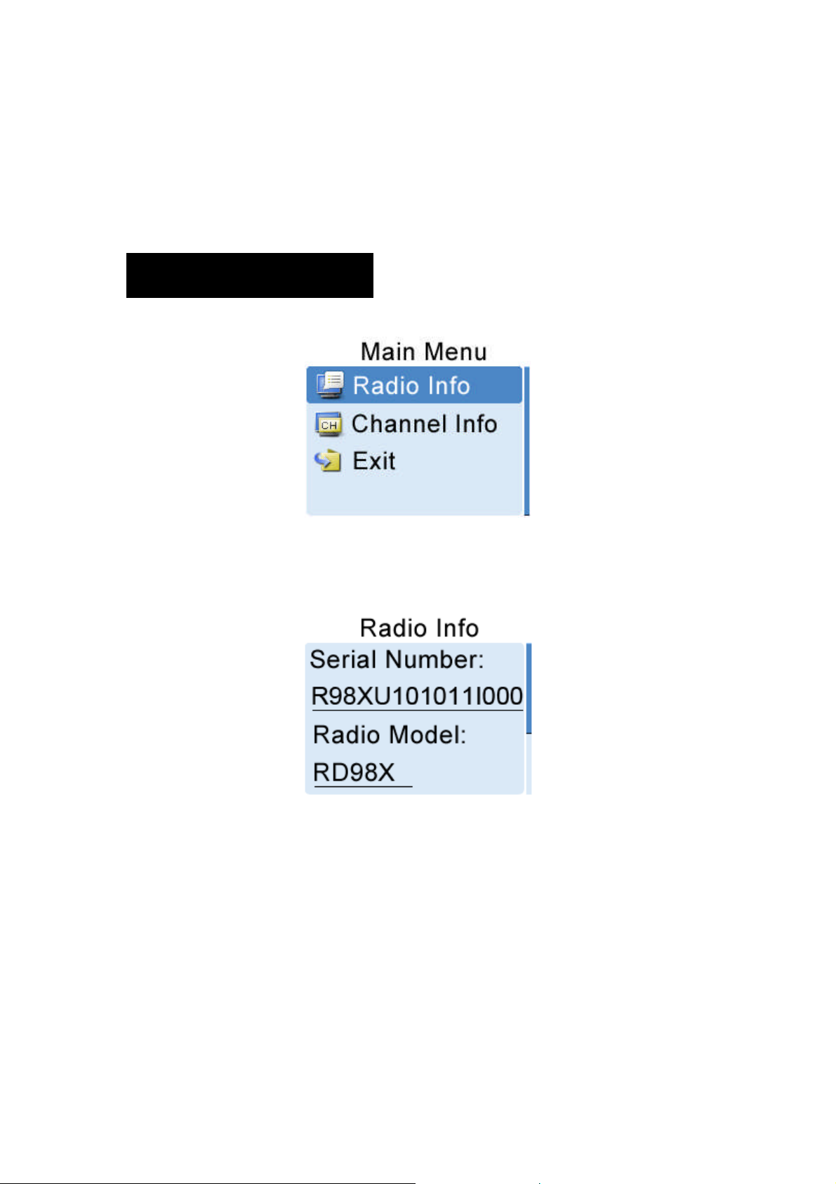
Radio Info
Under this menu, you can rotate the Navigation knob to view product information,
including Serial Number, Radio Model, Freq Range and Firmware Ver.
◆To access this menu:
1. In the home screen, press theNavigation knob to enter the main menu.
2. Rotate the knob to select the "Radio Info”option.
3. Press the knob again to view basic information of the repeater.
◆To exit this menu:
Just press the knob again.
15
Page 17
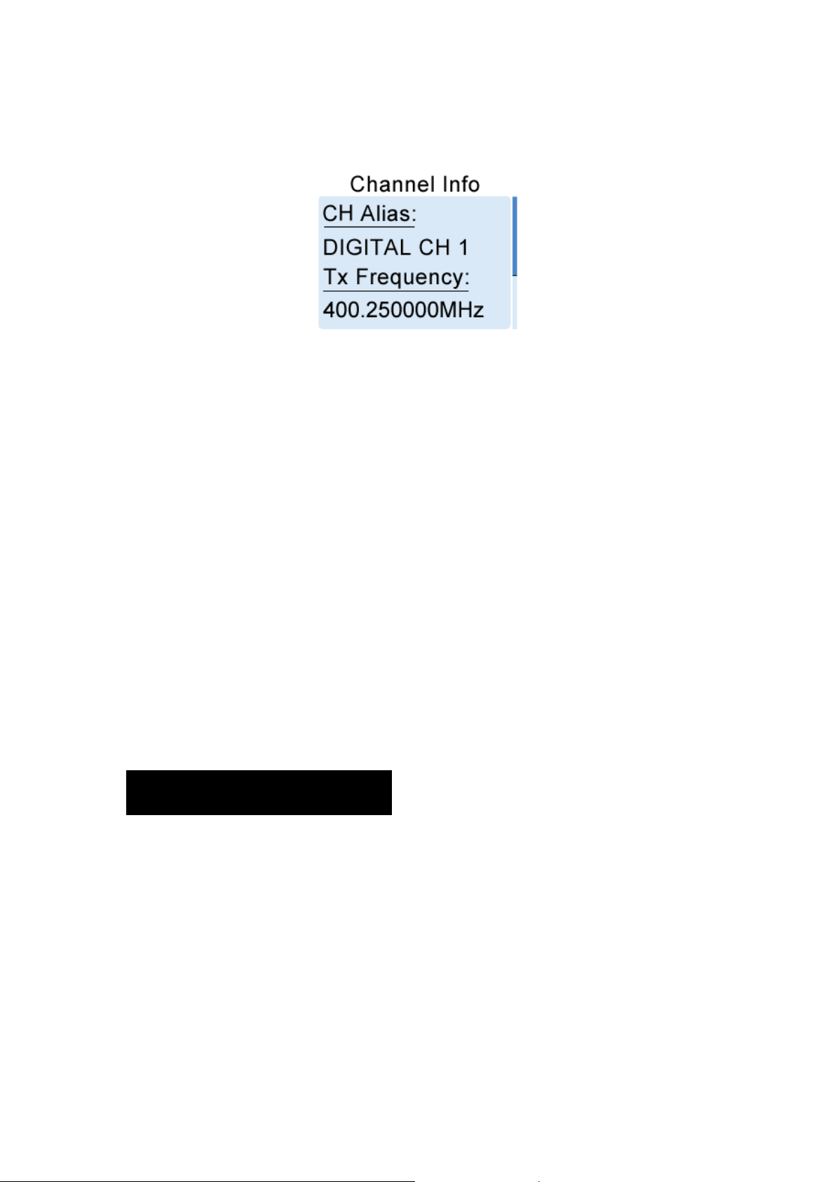
Channel Info
Under this menu, you can rotate the Navigation knob to view channel information,
including CHAlias, Tx Frequency, and so on.
◆To access this menu:
1. In the home screen, pressthe Navigation knob to enter the main menu.
2. Rotate the knob to select the "Channel Info”option.
3. Press the knob again to view information of the current channel.
◆To exit this menu:
Just press the knob again.
Exit
To exit from the main menu, rotate the Navigation knob to select the "Exit”option, and
then press the knob.
Alarm Information
The repeater can automatically detect its operation status in a real time way. When an
abnormality occurs, the LCD will give you a prompt message, and the Alarm Indicator will
glow red.
Over Temperature Alarm
When the temperature of PA module exceeds the normal range, the Alarm Indicator will
16
Page 18
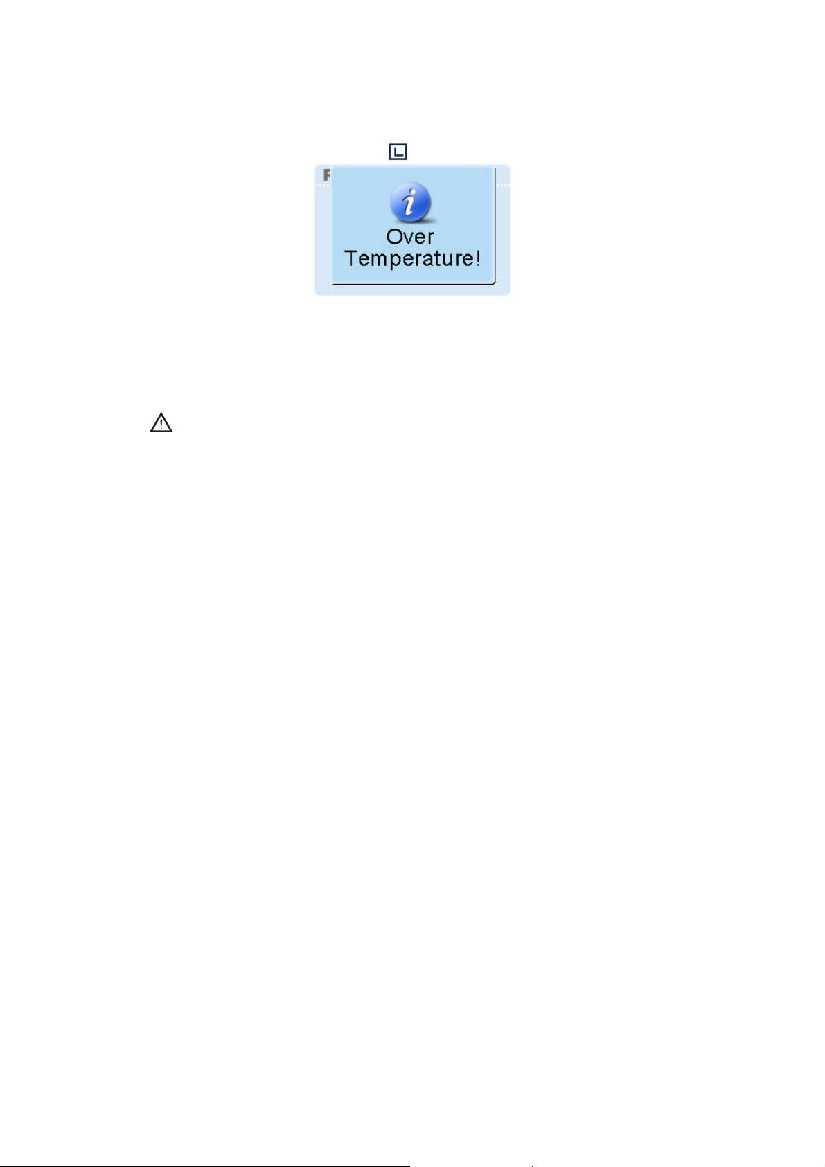
glow red and the LCD will display the prompt message below:
Then the repeater will stop transmitting, and you need to:
1. Check whether the temperature of heat sink surface is over 80℃. If yes, proceed with
Step 2 and 3 to find out the cause.
Caution: DO NOT touch the heat sink surface to avoid burn. You can use a digital
thermometer with thermocouple to measure the temperature value.
2. Check whether ambient temperature and ventilation conditions satisfy the foregoing
installation requirements.If not, please make improvements as soon as possible.
3. Check if connection between the transmitter and RF cable or antenna feeder is loose
or damaged. Poor connection between them could cause high TX power, which would
make the temperature of heat sink rise quickly. If yes, secure or replace the cable or
antenna feeder.
4. If the above measures fail to solve the problem, contact your local dealer for technical
support.
When temperature falls into normal range, the prompt message will disappear, and the
Alarm Indicator will go out.
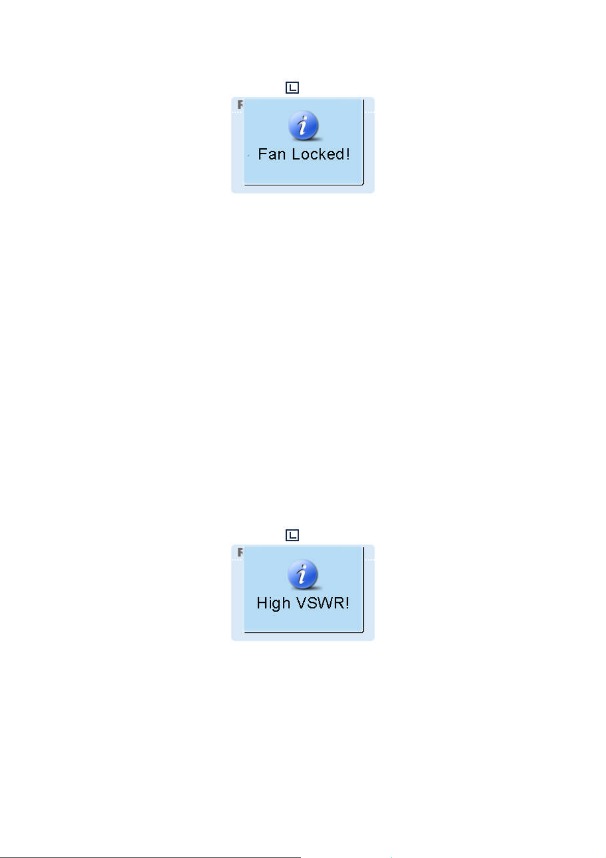
Fan Failure Alarm
When the fan fails to work, the Alarm Indicator will glow red and the LCD will display the
prompt message below:
17
Page 19
Then the repeater will automatically work at low TX power, to protect the transmitter from
overheating. You need to:
1. Check whether the fan is blocked by an object. If yes, remove it.
2. If you cannot solve the problem, contact your local dealer for technical support.
When the fan recovers normal operation, the prompt message will disappear, and the
Alarm Indicator will go out.
VSWR Alarm
High VSWR (voltage standing wave ratio) of TX antenna connector could result in
damage to the PA, and even failure of the transmitter. When the VSWR exceeds the
normal range, the Alarm Indicator will glow red and the LCD will display the prompt
message below:
Then the repeater will automatically works at low TX power.You need to:
1. Check if the operating frequency of repeater is in line with that of antenna. Both
frequency mismatch and improper antenna could result in poor transmitting
performance and even damage to the transmitter. If yes, please contact your local
dealer to replace the antennaor reprogram your product.
18
Page 20
2. Check if the connection between the transmitter and RF cable or antenna feeder is
loose or damaged. If yes, secure or replace the cable or antenna feeder.
3. If you cannot solve the problem, contact your local dealer for technical support.
When the VSWR falls within the normal range, the prompt message will disappear, and
the Alarm Indicator will go out.
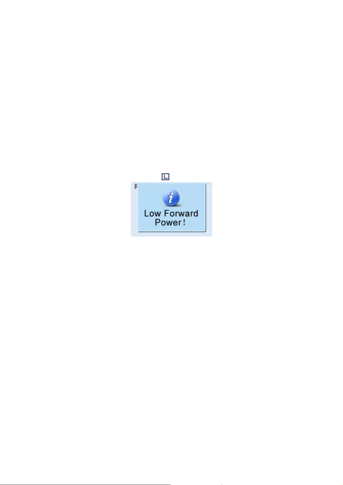
Low Forward Power Alarm
When the forward power is below the preset value, the Alarm Indicator will glow red and
the LCD will display the prompt message below:
Then the repeater may continue transmission or terminate it, subject to the detection
result. You need to:
1. Check if the connection between the transmitter and RF cable or antenna feeder is
loose or damaged. If yes, secure or replace the cable or antenna feeder.
2. If you cannot solve the problem, contact your local dealer for technical support.
When the forward power is recovered to its normal value, the prompt message will
disappear, and the Alarm Indicator will go out.
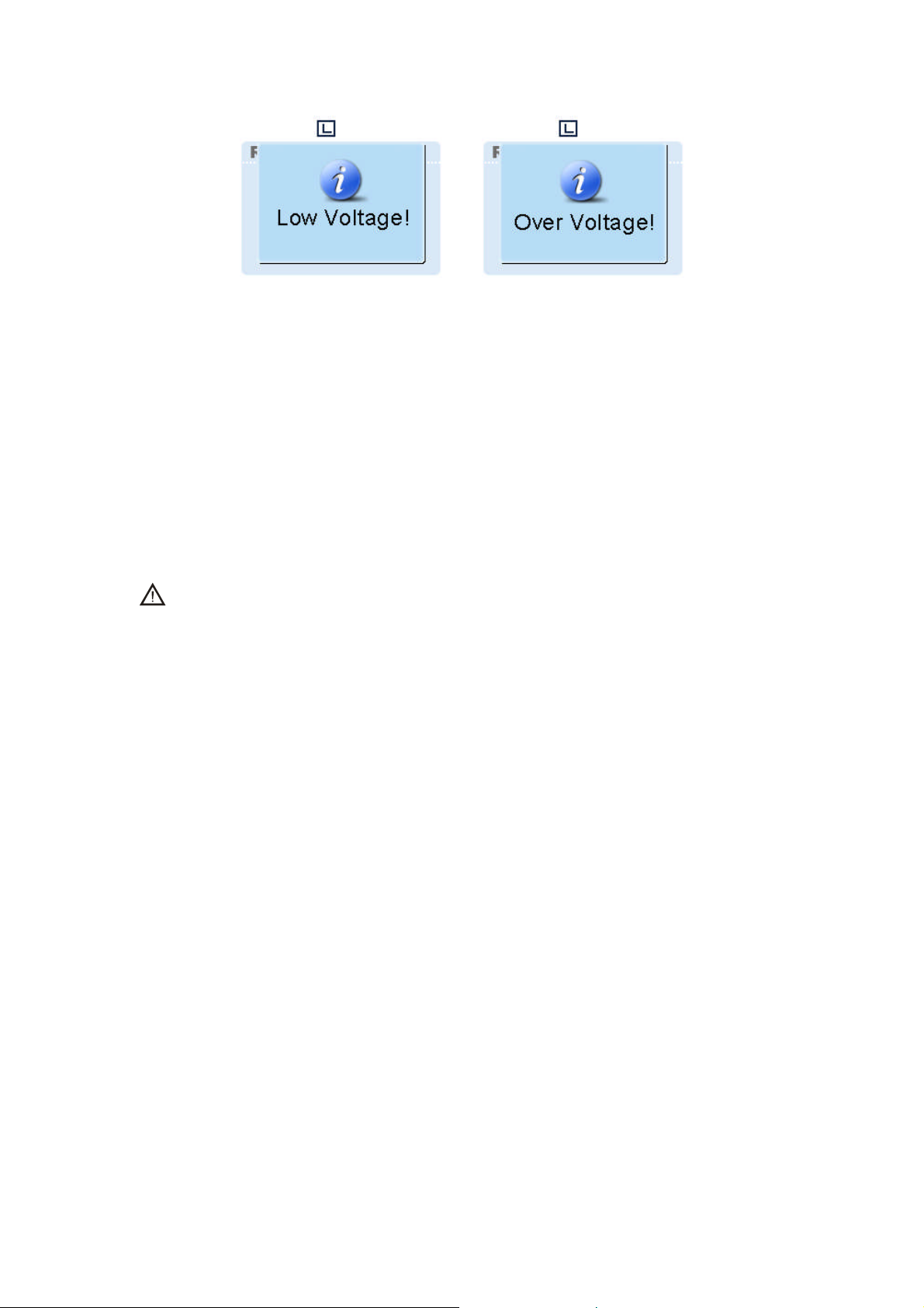
Over/Low Voltage Alarm
When power voltage is detected to be over or below the normal range (11V-15.6V) of
repeater, the Alarm Indicator will glow red and the LCD will display the prompt message
below:
19
Page 21
Low Voltage Alarm Over Voltage Alarm
Then the repeater will automatically stop working. You need to:
1. Check whether the power voltage is too low or too high. If yes, replace the DC power
supply or external battery.
2. Check whetherthe power cord is loose or damaged. If yes, secure or replace the cord.
3. If you cannot solve the problem, contact your local dealer for technical support.
When the voltage falls within the normal range, the prompt message will disappear, and
the Alarm Indicator will go out.
Caution: If low voltage is detected when the repeater is powered by an external
battery, please charge it in time. Disconnect the battery from the repeater
before charging.
20
Page 22
Troubleshooting
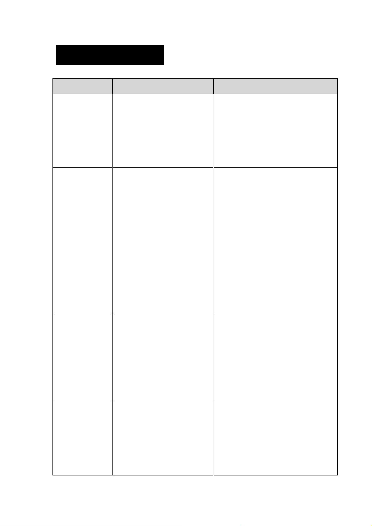
Phenomena Analysis Solution
a. Power cord is not connected
a. Properly connect the power cord
The repeater
cannot be
powered on.
Group members
cannot talk to
each other, or the
repeater cannot
communicate with
a subscriber
radio.
or is not securely connected
to the outlet.
b. Powercord fuse is
damaged.
a. TX/RX frequency of the
repeater is inconsistent with
that of portable/mobile
terminals.
b. Failed to repeat useful
signal due to strong
interference signal.
c. The group member is out
of the coverage of the
and ensure secure connection.
b. Check if the fuse has blown. If yes,
replace it with a new one.
a. Re-set frequencies.
b. If you cannot remove or bypass
the interference source, change
to operate at other frequencies.
c. Go within the coverage of the
repeater.
Group members
cannot talk to
each other, even
though RX
indication is
given.
Short
communication
range or poor
audio
repeater.
a. Your ID is inconsistent with
that of other group
members.
b. Inconsistent
CTCSS/CDCSS.
a. Leakage of signal energy
due to damaged
connection cable.
b. Loose connection
between the antenna
a. Set your ID to the same as that of
other members.
b. Re-set CTCSS/CDCSS.
a. Replace the cable with a new one
if necessary.
b. Secure or replace the cable.
c. Replace the cable with a new one.
d. Contact the manufacturer or your
21
Page 23

connector and the cable,
or loss of connection
c. Invisible damage of cable.
d. Duplexer is not properly
set (if the duplexer is
mounted).
If the above solutions can not fix your problems, or you may have some other queries,
please contact us or your local dealer for more technical support.
dealer to re-set the duplexer.
Care and Cleaning
To guarantee optimal performance as well as a long service life of the product, please
follow the tips below. Power off the repeater or disconnect it from the external battery
before cleaning.
Product Care
Keep the product at a place of good ventilation and heat dissipation to facilitate
normal work.
Do not place irrelevant articles on top of the product to ensure optimal heat
dissipation.
Do not pierce or scrape the product with any edged instruments or hard objects.
Keep the product far away from substances that can corrode the circuit.
Do not place the product in corrosive agents, solutions or water.
Product Cleaning
Remove the dust and fine particles on the repeater surface with a clean and dry
lint-free cloth or a brush regularly.
Use a non-woven cloth with neutral cleanser to clean the keys, control knobs, LCD
and jacks after long-time use. Never use chemical preparations such as stain
22
Page 24
removers, alcohol, sprays or oil preparations. Make sure the product is completely
dry before use.
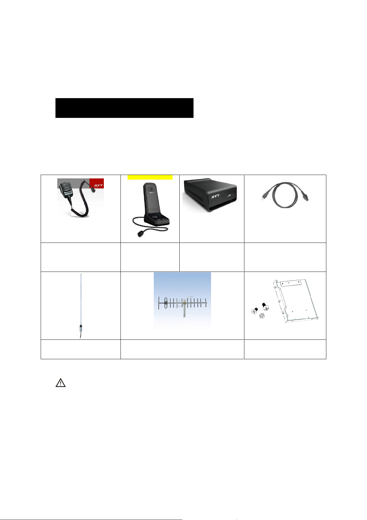
Optional Accessories
The following items are the main optional accessories for the product, and please consult
your local dealer for more information.
Palm Microphone
SM16A1 *
Omni-directional Antenna Directional Antenna Duplexer Bracket/Screws
Desktop
Microphone
SM10A1 *
External Power Supply
(320W, backup battery
applicable) PS22002
Programming Cable (USB
Port) PC37
(for DT11/DT12 only)
Caution: Use the accessories specified by Hytera only. If not, Hytera shall not be liable
for any losses or damages arising out of use of unauthorized accessories.
23
 Loading...