

Hytera PD98X User Manual

USER MANUAL
PD98X DIGITAL PORTABLE RADIO

Welcome to the world of
by-step procedur es for use. It also includes a troubleshooting guide. To avoid bodily injury or property loss caused by incorre ct ope ration,
please care fully read the Safety Information Booklet before use.
This manual is applicable to the following product:
PD98X Digital Portable Radio (X may represent 2, 5, 6 or 8)
Hytera a nd thank you for pur chasing this product. This manual includes a description of the functions and step-

Copyright Information
Hytera is the trademark or registered trade mark of
Hytera Communications Corporation Limited (the
Company) in the People's Republic of China (PRC) and/or
other c ountries or are as. The Company re tains the
ownership of its trademarks and pr oduct names. All other
trademarks and/or product names that may be used in this
manual are properties of their re spective owners.
The product described in this manual may include the
Company's computer progr ams stored in memory or other
media. Laws in PRC and/or other c ountries or areas
protect the exclusive rights of the Company with respec t
to its c omputer programs. The purc hase of this produc t
shall not be deemed to grant, either directly or by
implication, any rights to the purchase r regarding the
Company's c omputer programs. The Company's computer
programs may not be copied, modified, distributed,
decompiled, or reverse- e ngineered in any manne r
without the prior written consent of the Company.
Disclaimer
The Company e ndea vors to achieve the accurac y a nd
completene ss of this manua l, but no warranty of a cc uracy
or re liability is given. All the spe cifications and designs
are subjec t to c hange without notice due to c ontinuous
technologica l development. No part of this manual may
be copied, modified, translated, or distributed in any
manner without the prior wr itten consent of the Company.
We do not guarantee, for a ny particular purpose, the
accuracy, va lidity, timeliness, legitimacy or completeness
of the third- party products and contents involved in this
manual.
If you have any suggestions or would like to re ceive more
information, please visit our website at:
http://www.hyter a.com.
FCC Statement
This equipment has be en tested and f ound to comply with
the limits for a Class B digital device, pursuant to part 15
of FCC Rules. These limits are designed to provide
rea sonable protection against harmful interference in a
residential installation. This equipment genera tes and ca n
radiate radio freque ncy energy. If not installed and used
in acc ordance with the instructions, it may cause harmful
interfe rence to radio communications. However, there is
no guara ntee that interfe rence will not oc cur in a
particular installation. Verification of harmful
interfe rence by this equipment to radio or television
rec eption can be determined by turning it off and then on.
The user is encourage d to try to correct the interference
by one or more of the following mea sures:
l Reorient or relocate the receiving antenna . Incre ase
the separ ation betwee n the equipment and re ce iver.
l Connect the equipment into an outlet on a different
circuit to that of the receiver's outlet.
l Consult the dealer or an expe rienc ed ra dio/TV
technician for help.
Operation is subject to the following two conditions:
l This device may not c ause ha rmful interfere nce.
l This device must acce pt any interfe rence rece ived,
including interfer ence that may cause undesired
opera tion.
Note: Changes or modifications to this unit not expr essly
approve d by the party re sponsible for compliance could
void the use r's a uthority to operate the e quipment.
Compliance with RF Exposure
Standards
The radio complies with the following RF ener gy
exposure standards a nd guidelines:
l United States Fede ral Communications Commission,
Code of Federa l Regulations; 47 CFR § 1.1307,
1.1310 and 2.1093
l American National Standar ds Institute
(ANSI)/Institute of Electrical a nd Elec tronic
Engineer s (IEEE) C95. 1:2005; Cana da RSS102 Issue
5 March 2015
l Institute of Electrical a nd Elec tronic Engineers
(IEEE) C95.1:2005 Edition
RF Exposure Compliance and
Con trol Guidelines and Operating
Instructions
To control your exposure and ensure compliance with the
occupational/controlled environmental exposure limits,
always a dhere to the following pr ocedures.
Guidelines:
l Do not remove the RF Exposure Label from the
device .
l User awa reness instructions should accompany
device when transferred to other users.
l Do not use this device if the operational re quirements
descr ibed herein are not met.
Operating Instructions:

l Tra nsmit no more than the rated duty factor of 50%
of the time. To transmit (talk), pre ss the Push-to-Talk
(PTT) key. To receive calls, re lease the PTT key.
Transmitting 50% of the time, or less, is important
because the radio generates measura ble RF energy
only whe n transmitting (in terms of mea suring for
standards c ompliance) .
l Keep the radio unit a t least 2.5 cm away from the
fac e. Keeping the radio at the proper distanc e is
important as RF exposure decre ases with distance
from the a ntenna. The a ntenna should be ke pt away
from the face a nd eyes.
l When worn on the body, always place the ra dio in a n
approve d holder, holster, ca se, or body harne ss or by
use of the correc t c lip for this product. Use of nonapprove d ac ce ssories may result in exposure levels
which exceed the FCC's occupational/controlled
environmental RF exposure limits.
l Use of non- a pproved a ntennas, batteries, and
accessories causes the radio to exc eed the FCC RF
exposure guidelines.
l Contact your local dealer for the product's optional
accessories.
EU Regulatory Conformance
As certified by the qualified labor atory, the product is in
compliance with the essential r equire ments and other
relevant provisions of 2014/53/EU.
Please note that the a bove information is applicable to EU
countries only.
3

Contents
Contents 1
Documentation Inf ormation 2
IconC onventions 2
Notation Conventions 2
Packing List 2
Product Overview 3
Product Layout 3
Programmable Keys 3
Before Use 4
Charging the Battery 4
Installing the TF Card 4
Attaching the Battery 4
Attaching the Antenna 4
Attaching the Belt Cl ip 4
Attaching the Audio Accessory 5
BasicOperations 5
Turningthe R adio On or Off 5
Adjusting theVolume 5
Checking the Battery Power 5
Locking or Unlocking theKeypad 5
Using the Keypad 6
Switchingthe Operation Mode 6
Status Indications
LCD Icons 7
LED Indications 8
Call Services 8
GroupC all 8
Private Call 9
All Call 11
Broadcast Call (Trunking Only) 11
Include Call (Tr unking Only) 12
PhoneC all 12
Call on Analog Channel 14
Message Services 14
Viewing a Message 14
Sending a Message 14
Deletinga Message 15
General Features 15
Basic Settings 16
Audio Settings 19
OneT ouch Call/Menu 20
Scan 20
Hunt 21
Contact Management 22
TOT 23
Busy Channel Lockout 23
CustomizedSingle Tone 23
7
Priority Interrupt 23
PseudoT runk 23
XPT System 23
SFR 23
Roam 24
Work Order 24
Data Query 24
Call Divert 24
Call Priority 24
DGNA 25
Positioning 25
BT 26
BT Location 26
Voice w/Location 27
TF Application 27
Personal Safety Services 28
Communication Security Services 30
Supplementary Features 32
Troubleshooting 33
Care and Cleaning 35
Product Care 35
Product Cleaning 35
Optional Accessories 35
Abbreviations 35
Documentation Information
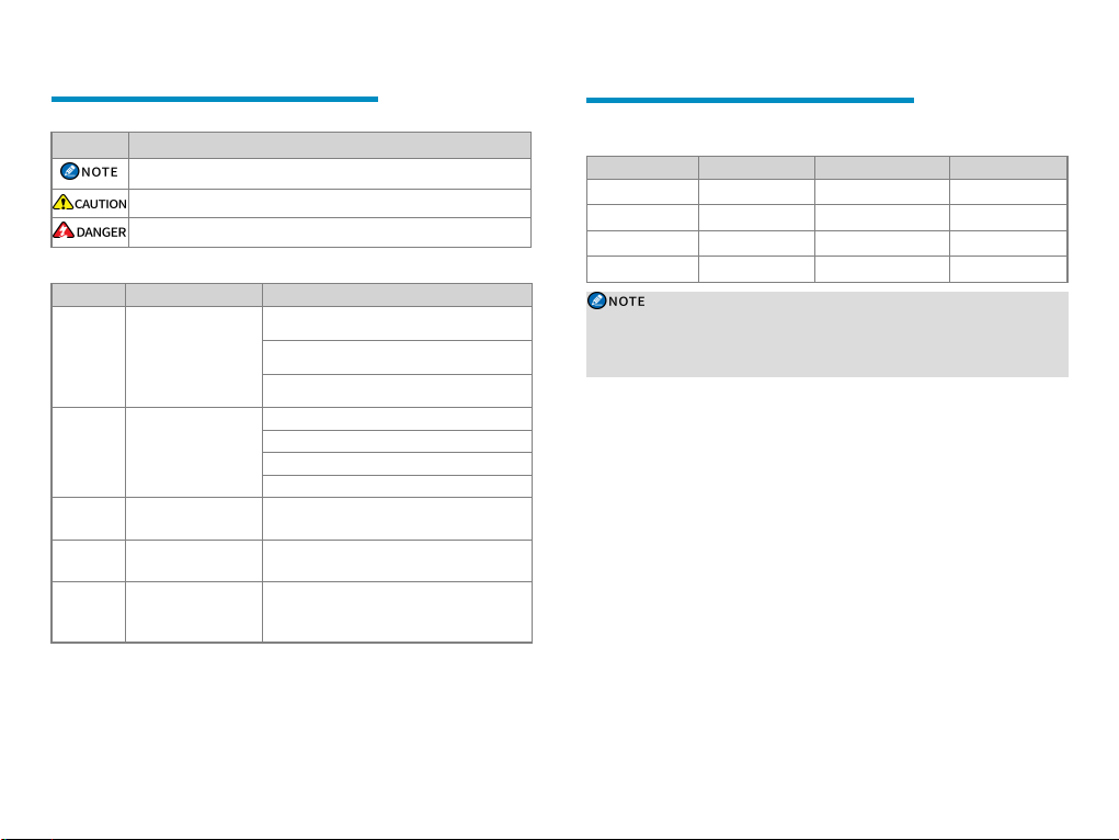
Icon Conventions
Icon Description
Indicates refere nces that c an further describe the related topics.
Indicates situations that could cause data loss or equipment damage.
Indicates situations that could cause minor bodily injury.
Notation Conventions
Item Description Example
Denotes menus, tabs,
para meter na mes,
Boldface
window names, dialogue
names, and hardware
buttons.
Denotes messages,
directories, file names,
" "
folder na mes, and
para meter va lues.
Direc ts you to ac cess a
>
multi-level menu.
Italic De notes document titles.
Couri er
Denotes c ommands and
New
their execution results.
To save the configuration, click A pply.
The Log Level Settings dialogue appears.
Press the PTT key.
The screen displays "Invalid Battery!".
Open "PDT_PSS.exe".
Go to "D:/opt/local".
In the Port text box, e nter "22".
Go to File > New .
For de tails about using the DW S, refe r to
Dispatch Workstation U ser Guide.
To set the IP a ddress, run the following
command:
vos-c md - m nam e IP
Packing List
Please unpack ca ref ully and c heck that you have received the following items. If any
item is missing or damaged, contact your dea ler.
Item Quantity ( PCS) Item Quantity (PCS)
Radio 1 Antenna 1
Battery 1 Belt Clip 1
Charger 1 Strap 1
Power Adapter 1 Documentation Kit 1
l Figures in this manual a re for reference only.
l Check whether the frequency band marked on the a ntenna label matches that on
the radio label. I f not, contact your de aler.
2
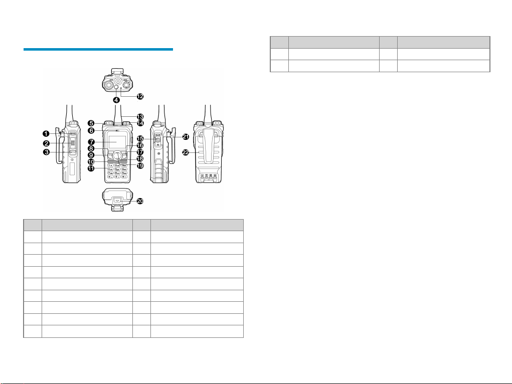
Product Overview
Product Layout
No. Part Name No. Part Name
1 Side Key 1 (SK1) 12 LED Indicator
2 Push-to-Talk (PTT) Key 13 Antenna
3 Side Key 2 (SK2) 14 On-Off/Volume Control Knob
4 Top Key (TK) 15 Acce ssory Connector
5 Channel/Group Selec tor Knob 16 Back/Subgroup Key
6 Microphone 17 P2/End Key
7 LCD Display 18 Up Key
8 OK/Menu Key 19 Down Key
9 P1/Answer Key 20 Battery Latch
No. Part Name No. Part Name
10 Speaker 21 Belt Clip
11 Numeric Keypad 22 Battery
Programmable Keys
You can request your dealer to progra m the following ke ys as shortcuts to radio fe ature s:
SK1, SK2,TK, P1/Answe r key, P2/End key, Back/Subgroup Key, Up key, and D own
key. Consult your dealer for assignable radio fea tures.
3
Before Use
Charging the Battery
l Read the Safe ty Information Bookle t before
charging.
l Use the a pproved charger to cha rge the ba ttery.
l The remaining lithium- ion battery power is
limited to 30% pursuant to the new lithium
battery shipment regulation approve d by
International Air Transport Association (IATA).
Before initial use, make sure to charge the ba ttery. You
can char ge either the standa lone battery or the radio with
battery a ttache d. It is recommended that the radio remain
turned off dur ing charging.
To char ge the battery, do as follows:
1. Inse rt the output connector of the power a dapter into
the port on the back of the c harger.
2. Plug the power adapter into a powe r outlet.
3. Place the battery into the cha rger.
The LED indicator on the charger shows the charging
status, a s described in the following table:
LED Indicator Charging Status
Flashes red slowly No ba ttery is placed on the c harger.
Glows red The batter y is being c harged.
Glows orange
Glows gree n The batter y is fully cha rged.
Flashes red ra pidly The battery fails to be charge d.
The battery is char ged to 90% or
above.
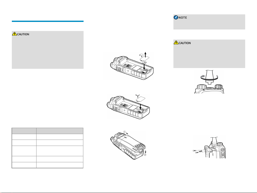
Installing the TF Card
If the TransFlash (TF) card is applica ble to your ra dio
and you ha ve a n ava ilable TF card, install the TF card as
follows:
1. Loosen the scre w on the TF ca rd cover, a nd then
remove the c over.
2. Place the TF c ard in the card slot.
3. Put the card cove r and screw back in place, and then
use the scre wdriver to tighten the screw.
Attaching the Battery
To remove the battery, make sure that the ra dio is
turned off, and then lift the ba ttery latch.
Attaching the Antenna
l Do not hold the r adio by the a ntenna and swing
it. This may affe ct the antenna performance and
shorten the life span of the a ntenna.
l Avoid excessive strength or destructive rotation
when installing the a ntenna.
Attaching the Belt Clip
1. Use a sc rewdriver to remove the screws on the back
of the radio.
2. Align the screw holes on the belt clip with those on
the back of the radio.
3. Install the scre ws into the holes, and then use the
scre wdriver to tighten them.
4
Attaching the Audio Accessory
For optimal waterproof and dustproof per formance,
do as follows:
l Attac h accessories with ca re to avoid scr aping
the silicone rubbe r surrounding the accessory
connector screw hole.
l Close the acce ssory connector cove r a nd fa sten
the scre w when no acce ssory is a ttached.
1. Loosen the screw on the acce ssory connector cove r,
and then open the cover.
2. Plug the a ccessory into the acc essory connector.
3. Rotate the scr ew on the ac ce ssory plug c lockwise.
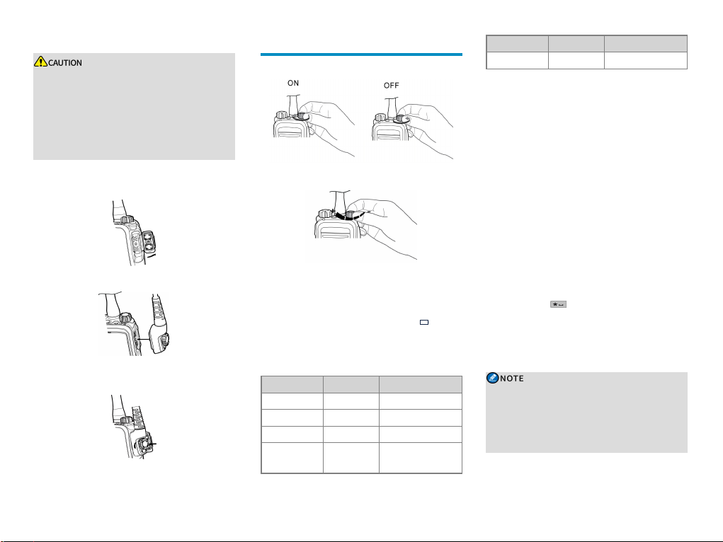
Basic Operations
Turning the Radio On or Off
Adjusting the Volume
Checking the Battery Power
To check the battery power, press and hold the
preprogrammed Batt er y P ower Indicator key. More
bars indicate more ba ttery power. The icon
that the battery runs low. In this case, recharge or replace
the ba ttery. The following table lists the battery power
indications.
LED Indicator Alert Tone Batt ery Power
Glows gree n Three beeps High
Glows orange Two beeps Medium
Glows red One beep Low
Glows red
Low batter y
tone
Under the low battery
threshold. Recharge or
indicates
LED Indicator Alert Tone Batt ery Power
replace the ba ttery.
Locking or Unlocking the Keypad
When the ke ypad is not in use, you can lock it to avoid
unintended operations.
l Auto Keypad Lock
The Auto Keypa d Lock fe ature allows the keypad to
be automatica lly locked when no operation is made or
no call or message is r eceived within the preset time
period.
To enable or disable the fe ature , on the home scree n,
go to M enu > Set tings > Radio Set > Keypad Lock.
l Manua l Keypad Lock or Unlock
To manually lock or unlock the keypad, do one of the
following:
» Press the preprogrammed Keypad Lock key.
» On the home sc reen, press the OK/Menu key a nd
then press
l Ke ypad Lock Backup
If the Keypa d Loc k Backup fea ture is enabled by
your dealer, the ra dio saves the last settings of ke ypad
or knob lock upon power- off.
You can go to M enu > Se ttings > Radio Set >
Optional Key to select more keys or knobs to be
locked, including the programmable ke ys,
Channel/Group Select or knob, On- Off /Volume
Control knob, and PTT key.
.
5
Using the Keypad
You can use the keypad to enter user a liases or IDs and
edit messages.
l To switch the input mode betwee n alphabetic mode
and numeric mode, press .
l To enter special characters, press in alphabetic
mode.
l To enter a spac e, pre ss in a lphabetic mode.
Switching the Operation Mode
Configured by your de aler, the radio can ope rate in
conventional mode or trunking mode.
To manua lly switch the oper ation mode, do one of the
following:
l Go to Me nu > M ode > Manual Switc h, a nd then
select the mode.
l Press the pre programmed Oper ation Mode Switc h
key.
To allow the radio to automatically switch to a mode
based on signal strength, do one of the following:
l Go to Me nu > Mode > Auto Switc h, and then se lect
Enable.
l Press the pre progra mmed Mode Auto Switch key.
With the Mode Auto Switch feature enabled, the LCD
displays .
Con vent ion al Mod e
In c onventional mode, ra dios on the same channe l ca n
establish data and voice communication. To ensure
normal c ommunication of the radio, you ha ve to select a
zone a nd a channel before using.
Selecting a Zone
A zone is a group of c hannels within the same operational
are a, a llowing you to manage channe ls in a conve nient
manner. The radio supports up to 64 z ones, ea ch of which
contains up to 256 channels.
To select a zone, do one of the following:
l Go to Me nu > Zone, press the Up or Down key to
select a zone, and then press the OK/Menu ke y.
l Press the pre programmed Zone U p or Zone Dow n
key.
Selecting a Chann el
l Rotate the Channel Selec tor knob.
l Press the preprogrammed Channel Up or Channel
Down key.
l To switch to the preset channe l, press the
preprogrammed P rese t Channel key.
If the Channel Notify f eature is enabled, the radio
automatically notify you of the curre nt channel upon
power-on or cha nnel change.
Trun king Mod e
In trunking mode, the radio automatically hunts for a n
available base station (BS) to register with. During
hunting, the LCD displays “ Registering. Please wait!” a nd
the icon , and the LED indicator flashes orange slowly
with an alert tone. After succ essful registration, the radio
can communicate with a private c ontact, group, or
subgroup.
Selecting a Group or a Private Contact
l Rotate the Group Sele ctor knob.
l Press the Back/Subgroup Key or go to M enu >
Subgroup, press the Up or Down key to se lect a
subgroup, and the select the group or private c ontact.
l Press the preprogrammed Group/Private C ontact
Up or Gr oup/Private Contact D own key.
Selecting a Subgr oup
A subgroup consists of multiple groups or private
contac ts.
To select a subgroup, do one of the following:
l Press the Back/Subgroup Key or go to M enu >
Subgroup, and then pre ss the Up or D own key.
l Press the preprogrammed Subgroup Up or Subgroup
Down key.
6
Status Indications
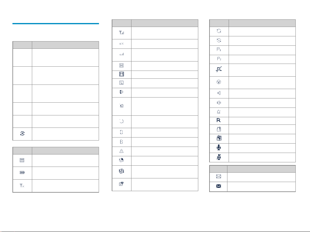
LCD Icons
Operation Mode Icon s
Icon Radio Status
Direc t Mode: In conve ntional mode, the
DM
radio communicates with another r adio
directly.
Repeater Mode: In conventional mode, the
RM
radio communicates with another r adio
through a repeater.
Trunking Mode - Digital W ide: In trunking
TM-DW
mode, the radio oper ates under multiple
interconne cted BSs.
Trunking Mode - Digital Local: In trunking
TM-DL
mode, the radio operates unde r a single BS.
In DMO, the SFR fea ture is e nabled the in
DM- R
the curr ent channel.
The W ork Mode Auto Switch f eature is
enabled.
Basic Status Icon s
Icon Radio Status
The Dual- Tone Multi-Frequency (DTMF)
keypad is ena bled.
The number of bar s indica tes the c harge
left in the battery.
There is no signal in c onventional or TMDW mode.
Icon Radio Status
The number of bars indicates the signal
strength in c onventional or TM-DW mode.
There is no signal in TM-DL mode.
The number of bars indicates the signal
strength in TM-DL mode.
The ra dio ope rates in high power mode.
The ra dio ope rates in medium power mode.
The ra dio ope rates in low powe r mode.
An accessory is conne cted.
The Global Positioning System (GPS)
fea ture is enabled, and the ra dio has
rec eived va lid GPSdata.
The GPS feature is e nabled, but the radio
has not received valid GPS data.
The BT fea ture is enabled.
A BT a ccessory is connec ted.
The ra dio is in emergency mode.
The ra dio is roa ming.
The ra dio is detecting signal strength for
roadming.
The Scrambler or Encryption feature is
enabled.
Icon Radio Status
The ra dio is sca nning or hunting.
The ra dio stays on a non- priority channel.
The ra dio stays on priority channel 1.
The ra dio stays on priority channel 2.
The Non- Dedicated TSCC feature is
enabled.
The Voice Operated Tr ansmit (VOX)
fea ture is enabled.
The Monitor fea ture is enabled.
The spea ker is turned on.
The ra dio ope rates in silent mode.
The SFR feature is enabled.
An err or occ urs to the TF ca rd.
The TF card is almost full.
The Call Record Feature is enabled.
Short Data Icons
An err or occ urs to the Call Record feature.
Icon Radio Status
There is/are unread short message(s).
The inbox is full.
7
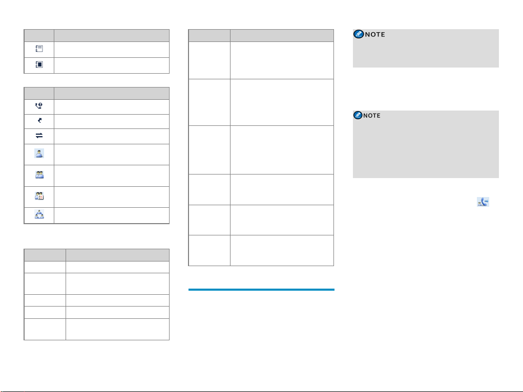
Icon Radio Status
There is/are unread wor k order(s).
The work or der list is full.
Call I cons
Icon Radio Status
There is/are missed ca ll(s).
The Call Divert feature is ena bled.
The ca ll setup mode is switch to full-duplex.
A private call is in progress or a private
contac t is on the contac t list.
A group call is in progress or a group
contac t is on the contac t list.
An a ll ca ll is in progress or an all call
contac t is on the contac t list.
An include ca ll is in progress.
LED Indications
LED Indicator Radio Status
Flashes green The radio is being turned on.
Flashes green
slowly
Glows gree n The radio is receiving.
Glows red The radio is tra nsmitting.
Flashes red
The ra dio is standby in trunking mode.
The ca lling radio is establishing a call in
trunking mode.
LED Indicator Radio Status
l Conventional mode: The radio is
Flashes orange
slowly
Flashes orange
rapidly
Glows orange
Flashes blue
every 3
seconds
Flashes blue
every 1.5
seconds
Flashes blue
every 0.1
seconds
scanning or roa ming.
l Trunking mode: The radio is
hunting.
l Conventional mode: The ra dio is in
emergency mode.
l Trunking mode: The c alled ra dio is
establishing a Full Off Air Call SetUp (FOACSU) call.
Call hang time: No voice is being
transmitted or rec eived on the channel
during a call. Dur ing the c all hang time,
you can pre ss and hold the PTT key and
speak.
The BT fea ture is enabled, but no BT
device is connected.
A BT de vice is connected.
The BT fea ture is being disabled.
Call Services
When you are speaking during a call, kee p the
microphone about 2.5 to 5 c m away from your mouth.
This e nsures optimal voice quality on the rec eiving radio.
In trunking mode, if the radio is not registered or
attached, or a n empty group is selec ted, you ca nnot
initiate a call.
Group Call
A group ca ll is a c all from an individual user in a group to
all other members in the group.
In trunking mode, the Auto Select Available Site
fea ture allows the radio to automatically re gister
with a BS where the current group is not limited after
powering on or during the group/BS changing. This
fea ture ensure s successful ca ll establishment
between the radio a nd the current group.
Initiating a Group Call
When you initiate a group c all, the radio displays .
Conventi onal Mode
l To initiate a group call to the preset contact on the
current channel, press and hold the PTT ke y.
l To initiate a group call through the contac t list, do as
follows:
1. Press the pre programmed Contact List or
Favorite Contac t List ke y, or go to M enu >
Contact > Contact List or Favor ite Contac t.
2. Select the gr oup contact.
3. Press and hold the PTT key.
l To initiate a group call through the keypad, do as
follows:
8
 Loading...