

Hytera PD79XIS Owner's Manual

OWNER' S MANUAL
PD79 XIS DIGI TAL PORTAB LE RADIO

Welcome to the world of Hytera and thank you for purchasing this product. This manual includes a description of the functions and stepby-step procedures for use. It also includes a troubleshooting guide. To avoid bodily injury or property loss caused by incorrect ope ration,
please carefully read the Safety Information Booklet before use.
This manual is applicable to the following product:
PD79X IS Digital Portable Radio (X may repre sent 2, 5, 6 or 8)

Copyright Information
Hytera is the tra demark or registered trademark of
Hytera Communications Corporation Limited (the
Company) in the People's Republic of China (PRC) and/or
other countries or areas. The Company retains the
ownership of its trademarks and product names. All other
trademarks and/or product names that may be used in this
manual are properties of their respective owners.
The product described in this manua l may include the
Company's computer programs stored in memory or other
media. Laws in PRC and/or other countries or areas
protect the exclusive rights of the Company with respect
to its computer programs. The purchase of this product
shall not be deemed to grant, either directly or by
implication, any rights to the purchaser regarding the
Company's computer programs. The Company's computer
programs may not be copied, modified, distributed,
decompiled, or reverse- engineered in any manner
without the prior written consent of the Company.
Disclaimer
The Company endeavors to achieve the accuracy and
completene ss of this manual, but no warra nty of accura cy
or reliability is given. All the specifications and designs
are subject to change without notice due to continuous
technologica l development. No part of this manual may
be c opied, modified, translated, or distributed in any
manner without the prior written consent of the Company.
We do not guarantee, for any particular purpose, the
accuracy, validity, timeliness, legitimacy or completeness
of the third-party products and contents involved in this
manual.
If you have any suggestions or would like to rece ive more
information, please visit our website at:
http://www.hytera.com.
FCC Statement
This equipment has been tested a nd found to comply with
the limits for a Class B digital device, pursuant to part 15
of FCC Rules. These limits are de signed to provide
reasonable protection against harmful interference in a
residential installation. This equipment generates and can
radiate radio frequency energy. If not installed and used
in accordance with the instructions, it may c ause harmful
interfe rence to radio communications. However, there is
no gua ra ntee that interference will not occ ur in a
particular installation. Verification of harmful
interfe rence by this equipment to ra dio or television
reception can be determined by turning it off and then on.
The user is encouraged to try to correct the interference
by one or more of the following measures:
l Reorient or relocate the receiving antenna. Increase
the separation between the equipment and receiver.
l Connect the equipment into an outlet on a different
circuit to that of the receiver's outlet.
l Consult the dealer or an experienced radio/TV
technician for help.
Operation is subject to the following two conditions:
l This device may not cause harmful interference .
l This device must accept any interferenc e received,
including interference that may ca use undesired
operation.
Note: Changes or modifications to this unit not expressly
approved by the party responsible for compliance c ould
void the user's authority to operate the equipment.
Compliance with RF Exposure
Standards
The radio complies with the following RF energy
exposure standards and guidelines:
l United States Federa l Communications Commission,
Code of Federal Regulations; 47 CFR § 1.1307,
1.1310 and 2.1093
l American National Standards Institute
(ANSI)/Institute of Electrical and Electronic
Engineers (IEEE) C95. 1:2005; Canada RSS102 Issue
5 March 2015
l Institute of Electrical and Electronic Engineers
(IEEE) C95.1:2005 Edition
RF Exposure Compliance and
Control Guidelines and Operating
Instructions
To control your exposure and ensure compliance with the
occupational/controlled environmental e xposure limits,
always adhere to the following procedures.
Guidelines:
l Do not remove the RF Exposure Label from the
device .
l User awareness instructions should a ccompany
device when transferred to other users.
l Do not use this device if the operational requirements
described herein are not met.
Operating Instructions:

l Transmit no more than the rated duty factor of 50%
of the time. To transmit (talk), press the Push-to-Talk
(PTT) ke y. To rec eive calls, release the PTT key.
Transmitting 50% of the time, or less, is important
because the radio generates measura ble RF energy
only when transmitting (in terms of measuring for
standards compliance).
l Keep the radio unit at least 2.5 cm away from the
face. Ke eping the radio at the proper distance is
important as RF exposure decrea ses with distance
from the antenna. The antenna should be kept away
from the face and eyes.
l When worn on the body, always place the radio in an
approved holder, holster, case, or body harness or by
use of the correct clip for this product. Use of nonapproved a ccessories may re sult in exposure levels
which excee d the FCC's occupational/controlled
environmental RF exposure limits.
l Use of non- approved antennas, batteries, and
accessories c auses the radio to exceed the FCC RF
exposure guidelines.
l Contact your local dealer for the product's optional
accessories.
IC Statement
The device has been tested and c omplies with SAR limits,
users can obtain Canadian information on RF exposure
and c ompliance .
Après examen de ce matériel aux conformité aux limites
DAS et/ou aux limites d’intensité de champ RF, les
utilisateurs peuvent sur l’exposition aux radiofréquenc es
et la conformité and compliance d’acquérir les
informations correspondantes
This device complies with Industry Canada licenseexempt RSS standard (s). Operation is subject to the
following two conditions:
l This device may not cause harmful interference .
l This device must accept any interferenc e received,
including interference that may ca use undesired
operation.
Le présent appareil est conforme aux CNR d'Industrie
Canada applicables aux appare ils radio exe mpts de
licence. L'exploitation est autorisée a ux deux conditions
suivantes: (1) l'appa re il ne doit pas produire de brouillage,
et (2) l'utilisateur de l'appa reil doit accepter tout
brouillage radioélec trique subi, même si le brouillage est
susceptible d'en c ompromettre le fonctionnement
EU Regulatory Conformance
As certified by the qualified laboratory, the product is in
compliance with the essential requirements and other
relevant provisions of 2014/53/EU, 2006/66/EC,
2011/65/EU, and 2012/19/EU.
Please note that the above information is applicable to EU
countries only.

Contents
D
ocumentation Conventions 2
Intrinsically Safe Radio Information 2
Product M arking 2
Explosives Classification 3
Hazardous Area Classification 3
No Misoperations 4
Safety Instructions 4
Compliance Standards 4
Packing List 5
Product Overview 6
Product Layout 6
Programmable Keys 6
Before Use 6
Charging the Battery 6
Attach the Battery 7
Attaching theAntenna 7
Attaching theBelt Clip 7
Attaching theAudio Accessory 7
Basic Operations 8
Turningthe Radio On or Off 8
Adjusting the Volume 8
Checking theBattery Power 8
Locking or Unlocking the Keypad 8
Using the Keypad 8
Switching the Operation Mode
8
Selecting a Zone andChannel 8
Status Indications 9
LCD Icons 9
LED Indications 10
Call Services 10
Group Call 10
Private Call 11
PhoneCall 13
All Call 14
Broadcast Call (Trunking Only) 15
Include Call (Trunking Only) 15
Call on Analog C hannel (Conventional
Only) 15
Message Services 16
Viewing Messages 16
Sending a Message 16
Deleting a Message 16
Feature Description 17
Basic Settings 17
Contact M anagement 18
Audio Optimization 19
MIC & SPK 19
OneTouchCall/Menu 20
Scan
20
Hunt 21
Roa
m
21
Talk Around 21
Time-out Timer 21
VOX 22
Call Di vert 22
Call Priority 22
DGNA 22
GPS 22
Work Order 23
Data Query 23
Control Services 24
Analog Services 24
Personal Safety Services 25
Communication Security Services 26
Troubleshoot ing 27
Care and Cleaning 29
Product Care 29
Product Cleaning 29
Optional Accessories 29
Abbreviations 29
1

Documentation Conventions
Icon Conventions
Icon Description
Indicates references that c an further
describe the related topics.
Indicates situations that could cause data
loss or equipment damage.
Notation Conventions
Item Description Example
Boldface
Denotes menus,
tabs, parameter
names, window
names, dialogue
names, and
hardware
buttons.
To save the configuration,
click Apply.
The Log Leve l Sett ings
dialogue appears.
Press the PTT key.
" "
Denotes
messages,
directories, file
names, folder
names, and
parameter
values.
The screen displays
"Invalid Battery!".
Open "PDT_PSS.exe".
Go to "D:/opt/local".
In the Port text box, enter
"22".
>
Directs you to
access a multilevel menu.
Go to File > Ne w.
Item Description Example
Italic
Denotes
document titles.
For details about using the
DWS, refer to Dispatch
Workstation User Guide.
Cour ier
New
Denotes
commands and
their execution
results.
To set the IP address, run
the following command:
vos- cmd - m na me
IP
Intrinsically Safe Radio
Information
l Observe the following safety instructions when
using the product, so as to ensure safe and
reliable operations. Failure to observe the
instructions may result in danger or violation of
applicable regulations.
l To avoid possible interference with blasting
operations, always turn off the product when
you are near electrical blasting c aps, in a
blasting area , or in areas posted "Turn off twoway radios". Obey all signs a nd instructions.
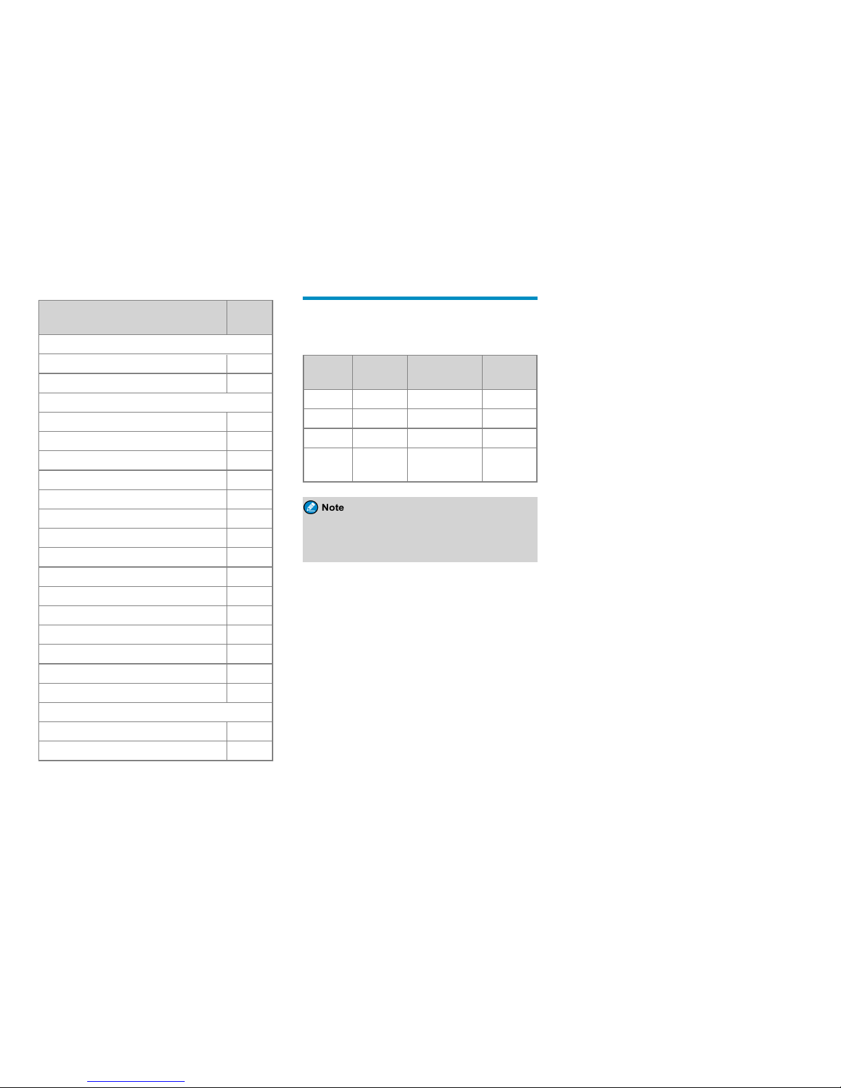
Product Marking
The table below lists the intrinsic safety information of the
product.
Certificate
Number
Marking
IECEx FMG
15.0027X
Ex ia IIC T3 Ga – 20°C ≤ Ta ≤
+55°C
Ex ia I Ma – 20°C ≤ Ta ≤ +50°C,
IP5X
Ex ia IIC T3 Ga – 20°C ≤ Ta ≤
+50°C, IP5X
Ex ia IIIC T160°C Da –20°C ≤ Ta ≤
+50°C, IP5X
Ex ib I Mb –20°C ≤ Ta ≤ +50°C,
IP5X
Ex ib IIC T4 Gb – 20°C ≤ Ta ≤
+50°C, IP5X
Ex ib III C T120°C Db –20°C ≤ Ta ≤
+50°C, IP5X
FM13ATEX0023X
II 1 G Ex ia IIC T3 –20°C ≤ Ta ≤
+55°C
I M1 Ex ia I –20°C ≤ Ta ≤ +50°C,
IP5X
II 1 G Ex ia IIC T3 –20°C ≤ Ta ≤
+50°C, IP5X
II 1 D Ex ia IIIC T160°C –20°C ≤
Ta ≤+50°C, IP5X
II 2 G Ex ib IIC T4 – 20°C ≤ Ta ≤
+50°C, IP5X
II 2 D Ex ib IIIC T120°C –20°C ≤
Ta ≤+50°C, IP5X
2

Certificate
Number
Marking
FM16US0013X
Class I Division 1, Groups A,B,C,D
T3B –20°C ≤ Ta ≤+55°C
Class I,II,III, Division 1, Groups
A,B,C,D,E,F,G T3C –20°C ≤ Ta ≤
+50°C, IP5X
Class I, Division 2, Groups A,B,C,D
T4 –20°C ≤ Ta ≤ +50°C, IP5X
Class II,III, Division 2, Groups
E,F,G T4A – 20°C ≤ Ta ≤ +50°C,
IP5X
Class I, Zone 0, AEx ia IIC T3B –
20°C ≤ Ta ≤+55°C
Class I, Zone 0, AEx ia IIC T3C –
20°C ≤ Ta ≤+50°C, IP5X
Zone 20, AEx ia IIIC T160°C –20°C
≤ Ta ≤+50°C, IP5X
Class I, Zone 1, AEx ib IIC T4 –
20°C ≤ Ta ≤+50°C, IP5X
Zone 21, AEx ib IIIC T120°C –20°C
≤ Ta ≤+50°C, IP5X
FM16CA0013X
Class I Division 1, Groups A,B,C,D
T3B –20°C ≤ Ta ≤+55°C
Class I,II,III Division 1, Groups
A,B,C,D,E,F,G T3C –20°C ≤ Ta ≤
+50°C, IP5X
Class I Division 2, Groups A,B,C,D
T4 –20°C ≤ Ta ≤ +50°C, IP5X
Certificate
Number
Marking
Class I, Zone 0, Ex ia IIC T3B Ga –
20°C ≤ Ta ≤+55°C
Class I, Zone 0, Ex ia IIC T3C Ga –
20°C ≤ Ta ≤+50°C, IP5X
Zone 20, Ex ia IIIC T160°C Da –
20°C ≤ Ta ≤+50°C, IP5X
Class I, Zone 1, Ex ib IIC T4 Gb –
20°C ≤ Ta ≤+50°C, IP5X
Zone 21, Ex ib IIIC T120°C Db –
20°C ≤ Ta ≤+50°C, IP5X
The meaning of each part in the marking is described as
below:
l Ex: specific marking for explosion protec tion.
l ia/ib: type of protection. It indicates that the product
adopts intrinsic safety ia/ib suitable for use in zone s 0,
1, and 2 (gases) and zone s 20, 21, and 22 (dusts). For
details about the zones, see Hazardous Area
Classification.
l I/II/III: equipment group. Group I indica tes that the
product is intended for use in mines susceptible to
firedamp. Group II indica tes that the product is
intended for use in plac es with an explosive gas
atmosphere other than mines susceptible to firedamp.
Group III indicates that the product is intended for
use in places with an explosive dust atmosphere.
l A/B/C/D/E/F/G: gas group. It defines the type of
hazardous material in the surrounding atmosphere.
Groups A, B, C, and D are for gases, while groups E,
F, and G are for dusts and flyings.
l T3/T4: temperature class. T3 indicates that the
maximum surface temperature during product use is
200°C. T4 indicates that the maximum surface
temperature during produc t use is 135°C.
l T120°C/T160°C: It indicates that the maximum
surface temperature during product use is 120°C or
160°C.
l Ga/Ma/Da/Db: equipment protection level. It is the
level of protection that is given to equipment based on
the likelihood of its becoming a source of ignition a nd
distinguishing the differenc e between explosive gas
atmosphere s, explosive dust atmospheres, and the
explosive atmospheres in mines susceptible to
firedamp.
l IP5X: ingress protection code. It indicates the degre e
of protection against solids and liquids.
Explosives Classification
l I: firedamp
l II: explosive mixture (vapors and mists)
l III: explosive dusts (fibers or flyings)
Hazardous Area Classification
Haz ardous area is a potentially flammable or explosive
area with flammable or explosive gases, vapors, or liquids
or flammable dusts or fibers. Hazardous areas are
classified into the following types:
3

Hazardous
Substance
Present for
Long
Periods
(1000 hours
above per
year)
Present in
Normal
Operation
(10– 1000
hours per
year)
Present in
Abnormal
Operation
(10 hours
below per
year)
Gases Zone 0 Zone 1 Zone 2
Dusts Zone 20 Zone 21 Zone 22
l Zone 0: a plac e in which an explosive atmosphere
consisting of a mixture with air of dangerous
substances in the form of gas, va por or mist is present
continuously or for long periods or frequently.
l Zone 1: a plac e in which an explosive atmosphere
consisting of a mixture with air of dangerous
substances in the form of gas, vapor or mist is likely
to occur in normal operation occasionally.
l Zone 2: a plac e in which an explosive atmosphere
consisting of a mixture with air of dangerous
substances in the form of gas, vapor or mist is not
likely to occur in normal operation but, if it does
occur, will persist for a short period only.
l Zone 20: a place in which an e xplosive a tmosphere in
the form of a c loud of combustible dust in air is
present continuously or for long periods or
frequently.
l Zone 21: a place in which an e xplosive a tmosphere in
the form of a cloud of combustible dust in air is likely
to occur in normal operation occasionally.
l Zone 22: a place in which an e xplosive a tmosphere in
the form of a cloud of combustible dust in air is not
likely to occur in normal operation but, if it does
occur, will persist for a short period only.
No Misoperations
Stop operating the product and leave the blasting area
immediately when the intrinsic safety or integrity of the
product is endangered, and de liver it to your local dealer
for examination.
The safety or reliability of the product may be
endangered when:
l The product is stored improperly.
l The product is faulty.
l The product works with overload.
l The product ope rates beyond the tolerance or
threshold.
l The product is damaged during transportation.
l The product's housing is obviously damaged or
cracked.
l The logo or characters on the product are hard to be
recognized.
Safety Instructions
l Before using the product in a hazardous atmosphere,
ensure that the two screws fixing the battery are
correctly tightened.
l Ensure that the product is used only with the BL1813-
Ex battery.
l Ensure that the product is used only with the following
accessories: SM18N8- Ex or SM26N8- Ex remote
speaker microphone, EHN12-Ex earpiece, BC19 belt
clip, RO04 strap, LCY008, LCY009, LCY010, or
LCY011 leather case, AN0435H04, AN0435H05,
AN0435H15, AN0435H16, AN0435H21,
AN0435H22, AN0141H03, AN0141H04,
AN0141H09, AN0141H10, AN0141H11,
AN0141H12, AN0153H04, AN0153H05,
AN0153H10, AN0153H11, AN0153H12,
AN0153H13, AN0167H03, AN0167H04,
AN0167H09, AN0167H10, AN0167H11,
AN0167H12, AN0375H10, AN0375H11,
AN0375H14 and AN0375H15 antenna, and other
Hytera-specified accessories.
l Do not replace the battery or accessories in a
hazardous atmosphere.
l Charge the battery using the designated charger in a
non-hazardous atmosphere with a maximum ambient
temperature of 40ºC.
l Do not carry any standalone ba ttery in a hazardous
atmosphere .
l Do not use the product if its housing is damaged or
cracked.
l Do not block or open the pressure adjustment hole on
the product.
l Do not use a damaged antenna. A minor burn may be
caused when you touch a damaged antenna.
l Do not expose the product to direct sunlight for a long
time, nor place it close to a heating source.
l Do not dissemble or modify the product.
Unauthorized modification may negate the approval
rating of the product.
l Do not attempt to disassemble, destroy, or short-
circuit the battery. Never dispose of it in fire.
l Hold the product upright and keep its microphone 2.5
to 5 centimeters away from your mouth during use.
l If you wear the product, ensure that its antenna is at
least 2.5 centimeters away from your body during
transmission.
4
Compliance Standards
Standard
Issue
Date
IECEx
IEC-60079-0 (Ed. 6.0) 2011
IEC-60079-11 (Ed. 6.0) 2011
FM
CAN/CAS-C22.2 NO.60529(Ed. 5.0) 2005
CAN/CAS-C22.2 NO.0-M91 2006
CAN/CAS-C22.2 NO.61010-1(Ed. 3.0) 2012
CAN/CAS-C22.2 NO.213-M1987 2013
CAN/CAS-C22.2 NO.60079-11(Ed. 6.0) 2014
CAN/CAS-C22.2 NO.60079-0(Ed. 6.0) 2015
FM Class 3611 2004
FM Class 3810 2005
FM Class 3600 2011
FM Class 3640 2013
FM Class 3610 2015
ANSI/IEC 60529(Ed. 4.0) 2004
ANSI/ISA 60079-0(12.00.01) (Ed. 6.0) 2013
ANSI/ISA 60079-11(12.02.01) (Ed. 6.0) 2014
ANSI/ISA 61010-1(82.02.01) (Ed. 3.0) 2012
ATEX
EN 60079-0:2012+A11:2013 2012/2013
EN 60079-11 2012
Packing List
Please unpack carefully and check that you have
received the following items. If any item is missing or
damage d, please contact your dealer.
Item
Quantity
(PCS)
Item
Quantity
(PCS)
Radio 1 Antenna 1
Battery 1 Belt Clip 1
Charger 1 Strap 1
Power
Adapter 1
Documentation
Kit 1
Check whether the frequency band marked on the
antenna labe l matches that on the radio label. If not,
please contact your dealer.
5
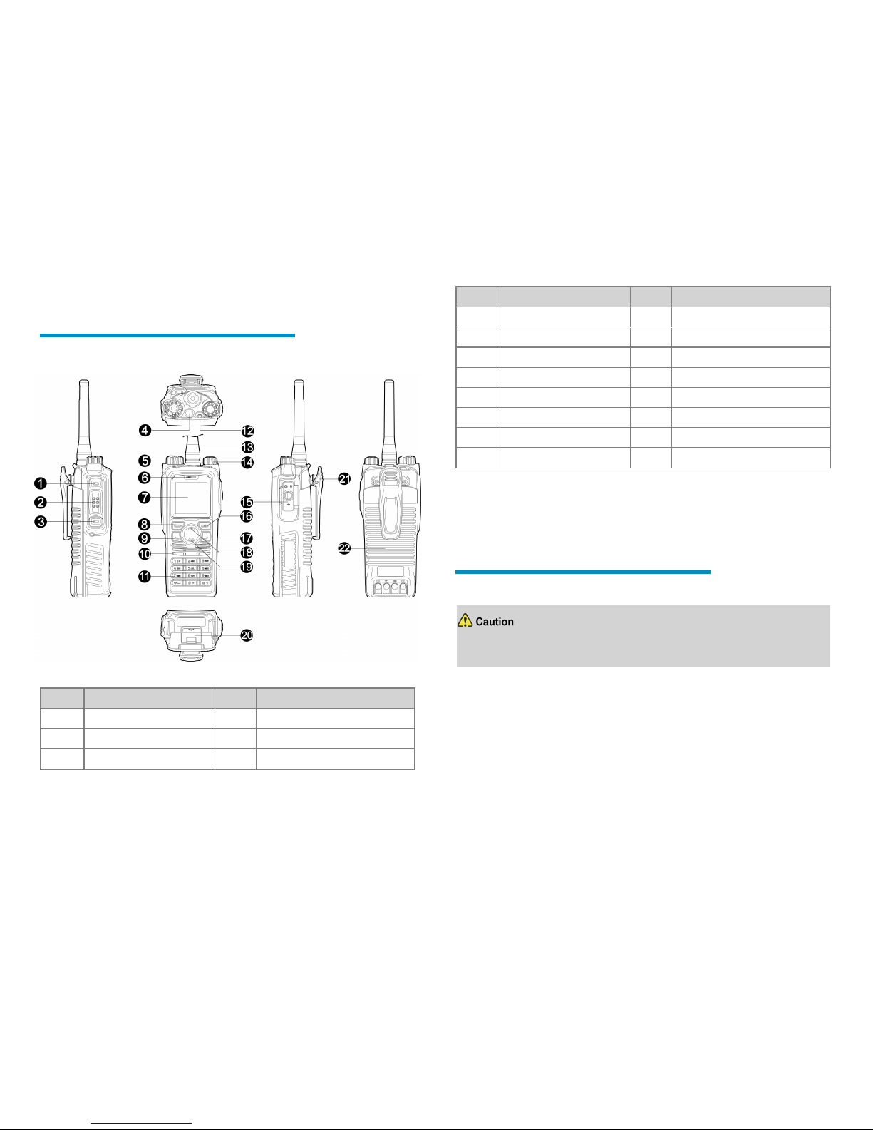
Product Overview
Product Layout
No. Part Name No. Part Name
1 Side Key 1 (SK1) 12 LED Indicator
2 Push-to-Talk (PTT) Key 13 Antenna
3 Side Key 2 (SK2) 14 On-Off/Volume Control Knob
No. Part Name No. Part Name
4 Top Key (TK) 15 Ac cessory Connector
5 Channel/Group Selector Knob 16 Back/Subgroup Key
6 Microphone 17 P2/End Key
7 LCD Display 18 Up Key
8 OK/Menu Key 19 Down Key
9 P1/Answer Key 20 Battery Latch
10 Speake r 21 Belt Clip
11 Numeric Keypad 22 Battery
Programmable Keys
You can re quest your dealer to progra m the following progra mmable keys as shortcuts to
assignable radio features: SK1, SK2, TK, P1 key, P2 ke y, U p key, and Down key.
Before Use
Charging the Battery
l Use the approved charger to charge the battery.
l Read the Safety Information Booklet before charging.
Before initial use, fully charge the battery to ensure optimum performance.
To charge the battery, do as follows:
1. Insert the output connec tor of the power adapter into the port on the back of the
charger.
2. Plug the power adapter into a power outlet.
3. Place the battery into the charger.
To determine the charging status, check the light-e mitting diode (LED) indicator on the
charger according to the following table:
6
LED Indicator Description
Glows re d The battery is charging.
Glows ora nge
The battery is charged to 90% or
above.
Glows gre en The battery is fully charged.
Flashes red slowly
The battery fails to make proper
contac t with the charger. In this
case, take the battery out of the
charger, and then place it into the
charger for prope r contact.
Flashes red rapidly
The battery fails to be charged. In
this c ase, please contact your
dealer to check whether the battery
or power adapter is damaged.
You can also charge the radio with battery attached.
It is re commended that your radio be turned off
during charging.
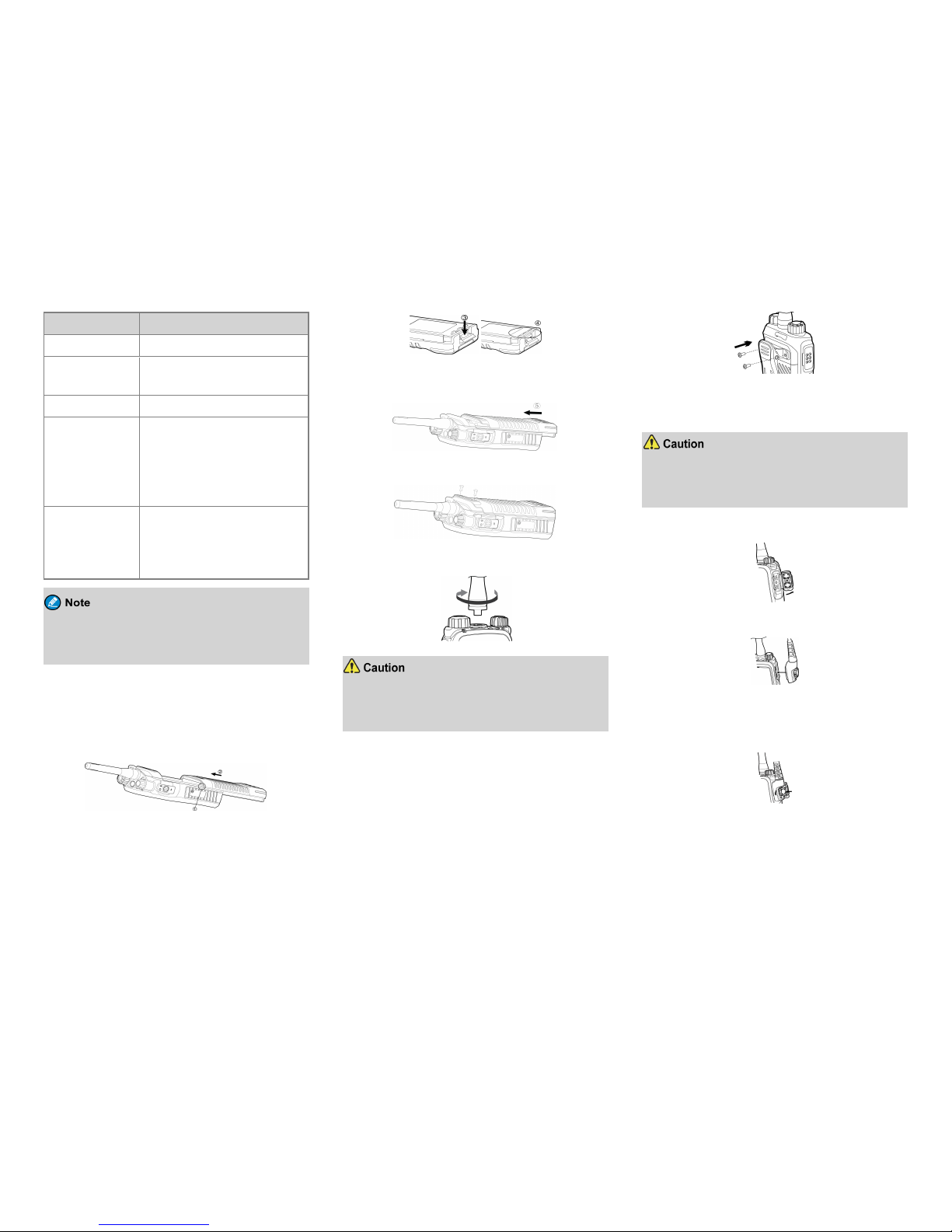
Attach the Battery
1 . Align the battery slots with the guide rails on the radio,
and then push the battery until the metal lock reache s the
bottom of the ra dio.
2 . Open the battery latch and exert force on it to retract
the metal lock into the battery housing completely.
3 . Push the battery until it is fully fitted into the slot, a nd
then release the battery latch.
4 . Tighten the two screws on the back of the radio.
Attaching the Antenna
Do not hold the radio by the antenna, because it
might reduc e the radio performance and life span of
the antenna.
Attaching the Belt Clip
1. Use a Phillips screwdriver to turn the screws counterclockwise on the back of the radio and remove them.
2. Align the screw holes on the belt clip with those on
the back of the radio.
3. Put the screws back in plac es as shown below, and
use the screwdriver to turn them clockwise untilhand
tight.
Attaching the Audio Accessory
For optimal waterproof a nd dustproof performance,
do close the acce ssory connec tor cover and fasten
the screw when no a ccessory is attached.
1. Open the accessory connector cover.
2. Plug the accessory into the a ccessory c onnector.
3. Rotate the screw on the accessory plug clockwise
until hand tight.
7
 Loading...