

Hytera PD79 Ex, PD792 Ex, PD795 Ex, PD796 Ex, PD798 Ex Owner's Manual

PD79X Ex
DIGITAL T RUNKING PORTABLE RADIO
OWNER’S M ANUAL

Preface
Thanks fo r your favor in our product . This manual is helpful fo r you to quick ly know how to us e the
produc t. For detailed feature s and operat ions, plea se refer to the Fe ature Desc ription a nd Opera-
tion Manual along with the product.
To avoid body inj ury or pro perty loss caused by misoperation, please read the Saf ety Infor mation
Booklet carefully before use.
This man ual is applicable to the f ollowing p roduct:
PD79X Ex Digital Por table Radi o (X may repre sent 2, 5, 6 or 8)
English

Icon Conventions
: indicates functions that are available on digital
channel only.
: indicates functions that are available on analog
channel only.
Functio ns marked wit h neither the above icons are
available on both analog and digital channels.
Disclaimer
Hytera Communications Corporation Limited (the
Company) endeavors to achieve the ac curacy and
compl eteness of this manual, but no warrant y of
accur acy or reliab ility is given. All the sp ecific ations
and desi gns are subject to chang e without no tice due
to continuous technology development. No part of
this manual may be copied, modified, translated, or
distributed in any manner witho ut the expres s writte n
permi ssion of us.
We do not guarantee, for any particular purpo se,
the accuracy, validity, timeliness, legitimacy or
compl eteness of the Third Par ty products and
contents involved in this manual.
If you have any s uggestio ns or would like t o learn
more det ails, pleas e visit our web site at: http://www.
hytera.com.
RF Radiation Information
This pro duct must be r estricted to operati ons in an
occupational/controlled RF exposure environment.
Users mu st be fully aware of the haz ards of the
exposur e and able to exercise cont rol over the ir RF
exposur e to qualif y for the high er exposure l imits.
RF Radiation Prole
Radio Freq uency (RF) i s a frequency of
elect romagnetic radiatio n in the range a t which radi o
signal s are transmitted. RF te chnology is widely used
in communicatio n, medicin e, food proc essing and
other e lds. It may gen erate radia tion during use.
RF Radiation Safety
In order t o ensure user h ealth, expe rts from r elevant
industries including science, engineering, medicine
and health work with international organizations to
develop standards fo r safe exposu re to RF radiat ion.
These st andards c onsist of:
●
United States Federal Communications
Commission, Code of Federal Regulations; 47CFR
part 2 sub-part J;
●
American National Standards Institute (ANSI)/
Institute of Electrical and Electronic Engineers
(IEEE) C95. 1-1992;
●
Institute of Electrical and Electronic Engineers
(IEEE) C95. 1 – 1999;
●
International Commission on Non-Ionizing Radiation
Protection (ICNIRP) 1998;
FCC Regulations
Federal Communication Commission (FCC) requires
that all radio commu nication products s hould meet t he
requirements set fo rth in the above standar ds before
they can b e marketed in the U.S, and the ma nufacturer
shall po st a RF label on t he produc t to inform us ers
of operational instructions, so as to enhance their
occup ational he alth agains t exposure to R F energy.
Operational Instructions and Training
Guidelines
To ensure optimal performance and compliance with
the occupational/controlled environment RF energy
exposure limits in the above standards and guidelines,
users sh ould transmit no more than 50% of the t ime
and always adhere to the f ollowing p rocedures:
●
RF energy will be generated only when the radio is
transmitting.
●
The radio must be 2.5 centimeters away from
human body when transmitting.
EU Regulatory Conformance
As cer tified by t he qualif ied labora tory, the pro duct
is in compliance with the essential requirements and
other re levant provisions of the D irective 19 99/5/EC.
Please n ote that the ab ove information is appl icable to
EU countries only.

Contents
Intrinsically Safe Radio Information ---------------------------------------------- 2
Equipment marking ----------------------------------------------------------------- 2
No Misoperations-------------------------------------------------------------------- 2
Safety Instructions ------------------------------------------------------------------ 2
Compliance Standards ------------------------------------------------------------ 2
Items in the Package ------------------------------------------------------------------- 3
Product Overview ----------------------------------------------------------------------- 3
Product Controls--------------------------------------------------------------------- 3
Programmable Keys ---------------------------------------------------------------- 4
LCD Icon ------------------------------------------------------------------------------ 4
LED Indicator ------------------------------------------------------------------------- 4
Before Use --------------------------------------------------------------------------------- 4
Attaching the Battery --------------------------------------------------------------- 4
Attaching the Antenna ------------------------------------------------------------- 5
Attaching the Belt Clip ------------------------------------------------------------ 5
Attaching the Accessories -------------------------------------------------------- 5
Charging the Battery --------------------------------------------------------------- 5
Checking the Battery Power ------------------------------------------------------ 5
Basic Operation-------------------------------------------------------------------------- 6
Turning the Radio On/Off --------------------------------------------------------- 6
Adjusting the Volume --------------------------------------------------------------- 6
Selecting a Zone -------------------------------------------------------------------- 6
Selecting a Channel ---------------------------------------------------------------- 6
Inputting via Keypad ---------------------------------------------------------------- 6
Locking and Unlocking the Keypad -------------------------------------------- 6
Managing the Contact ------------------------------------------------------------- 6
Call Services ------------------------------------------------------------------------------ 7
Private Call --------------------------------------------------------------------- 7
Group Call ---------------------------------------------------------------------- 8
Calls on Analog Channel (No Signaling) -------------------------------- 8
Emergency Call ---------------------------------------------------------------------- 8
Message Services ---------------------------------------------------------------- 8
Available Features ---------------------------------------------------------------------- 9
Troubleshooting ------------------------------------------------------------------------- 10
Care and Cleaning ---------------------------------------------------------------------- 11
Optional Accessories ------------------------------------------------------------------ 11
Specications ---------------------------------------------------------------------------- 12
1
Intrinsically Safe Radio Information
Equipment marking
FM/CAN
●
Class I, Zone 1 AEx/Ex ib IIC T4 Gb
●
Class II, III Div 1, Group E, F, G T120
℃
ATEX
●
II 2G Ex ib IIC T4
●
II 2D Ex ib IIIC T120℃ IP5X
●
I M2 Ex ib
IECEx
●
Ex ib IIC T4
●
Ex ib IIIC T120℃ IP5X
●
Ex ib I
Certicate Number
●
FM13ATEX0023X
●
FMG 13.0010X
No Misoperations
Stop ope rating thi s product and leave the explosive
atmosp here immed iately when t he safety o r integrit y
of the pro duct is enda ngered, an d deliver it to yo ur
local dealer for examination.
These it ems may endang er the product’s safet y or
integrity:
●
The radio is stored improperly;
●
The radio is faulty;
●
The radio works with overload;
●
The radio’s operational error or threshold value is
out of allowed range.
●
The radio is damaged during transportation;
●
The radio’s housing is obviously damaged or
cracked;
●
The radio logo or model is hard to be recognized;
2
Safety Instructions
●
●
●
●
●
●
●
●
●
●
●
●
Caution: To protect you against any
property loss, bodily injury or even death,
be sure to observe the following safety
instructions:
Use only the Ex-battery BL1807-Ex specied by the
Company. The use of other batteries may result in
Ex-protection (intrinsic safety) failure.
Charge the battery in a non-hazardous area only
with the designated charger.
Do not remove the battery from the radio in a
hazardous area.
Do not carry any standby battery into a hazardous
area.
Use the accessories specified by the Company
only. Do not replace the accessories in a hazardous
area.
Do not use a damaged antenna. If a damaged
antenna comes into contact with your skin, a minor
burn may result.
Do not expose the radio to direct sunlight for a long
time, nor place it close to a heating source.
Hold the radio upright and keep its microphone 2.5
to 5 centimeters away from your mouth during use.
If you wear a radio on your body, ensure its antenna
is at least 2.5 centimeters away from your body
during transmission.
Do not carry the radio into Zone 0 and 20.
Please do not use the radio out of the operating
temperature range specication of this product.
Do not attempt to repair and service the radio,
batteries and its accessories. Please contact your
dealer for repair and servicing.
Do not dissemble or redo the radio. Unauthorized
modication of the radio may result in termination of
Ex-protection (intrinsic safety) of the radio.
●
Improper usage of the product other than it is
intended to be used for will impair safety of the
product, yourself and surrounding environment.
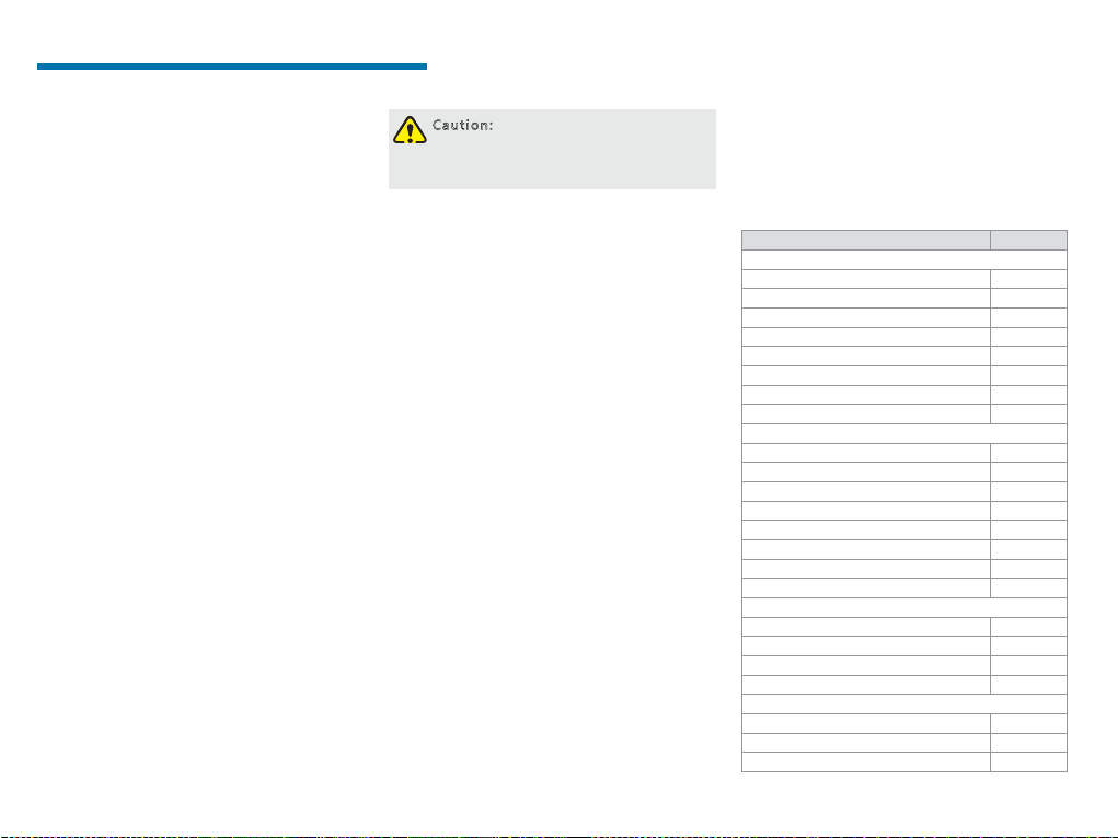
Compliance Standards
FM
FM Class 3 600 20 11
FM Class 3 611 2004
FM Class 3 810 2005
ANSI/IEC-60529(Ed. 4.0) 2004
ANSI/ISA-60079- 0(12.00.01) 2009
ANSI/ISA-60 079-11(12.02.01) 2012
ANSI/ISA-60079-31(12.10.03) 2009
ANSI/ISA-61010-1(82.02.01) 20 04
CAN
CAN/C SA-C22.2 No.0 -M91 2006
CAN/CS A-C22. 2 No.142-M1987 2009
CAN/CSA-C22.2 No.213-M1987 2008
CAN/C SA-C22.2 No.6 0079- 0 (Ed. 5.0) 20 11
CAN/C SA-C22.2 No.6 0079-11 (Ed. 5.0) 20 11
CAN/C SA-C22.2 No.6 0079- 31 (Ed.1.0) 2012
CAN/C SA-C22.2 No.6 0529 (Ed. 5.0) 20 05
CAN/ CSA- C22. 2 No.61010 -1 (Ed. 2.0) 2009
ATE X
EN 60079-0 (Ed. 5 .0) 2009
EN 60079-11 (Ed. 6.0) 2012
EN 60079-31 (Ed. 1.0) 2009
EN 6052 9+A1 (Ed. 2.0) 1992
IECEx
IEC- 60079 -0 (Ed. 6.0) 2 011
IEC- 60079 -11 (Ed. 6.0) 20 11
IEC- 60079 -31 (Ed. 1.0) 2008
Standard Issue D ate
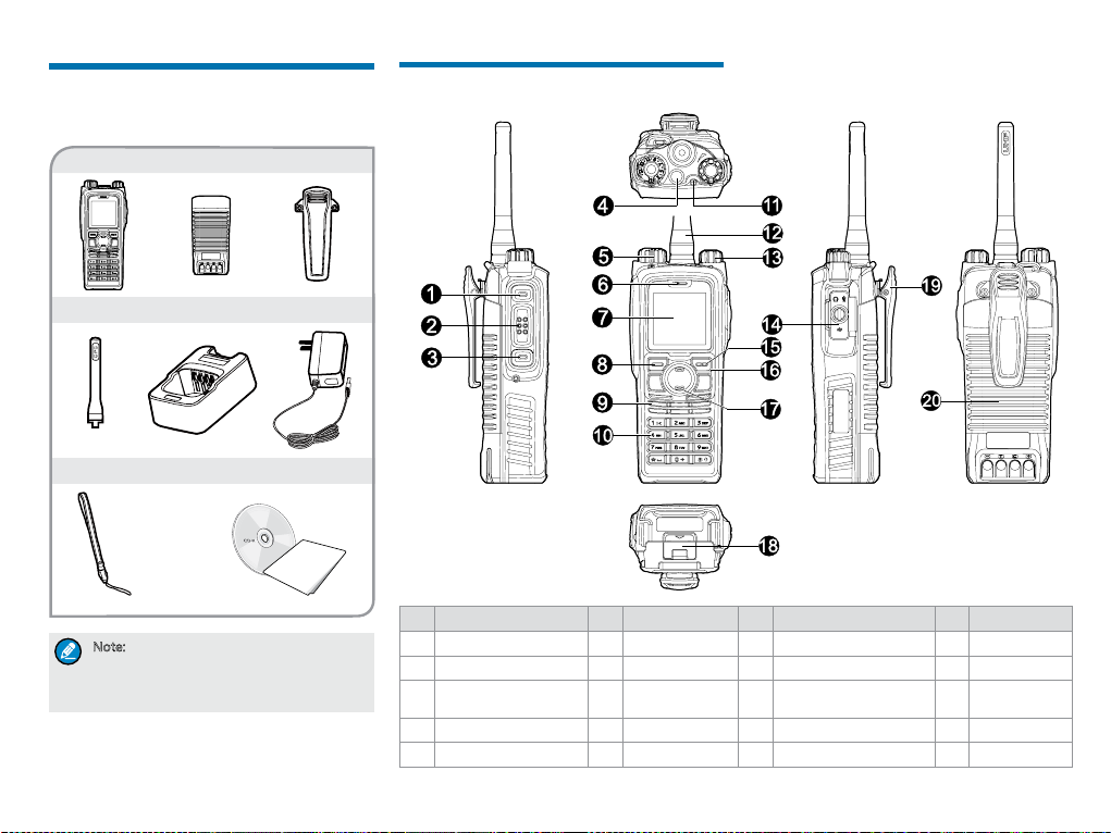
Items in the Package
Please unpack carefully and ch eck that all i tems listed
below ar e received. If any item is mis sing or dama ged,
please contact your dealer.
Radio
Battery
Belt Clip
Product Overview
Product Controls
ChargerAntenna
Strap
Note: The frequency band is marked on the
label of the antenna; if not, please refer to
the label on the radio for frequency band
information.
Power Adapter
Documentation Kit
OWNER'S MANUAL
No. Part Name No. Part Name No. Part Name No. Part Name
SK1 (Side Key 1)
1
PTT (Pu sh-to-Talk) Key
2
SK2 (Si de Key 2)
3
TK (Top Key)
4
Channel Selector Knob
5
Microphone
6
LCD Display
7
OK/ Menu Key
8
Speaker
9
Numeric Keypad
10
LED Indicator
11
Antenna
12
Power On-Of f/Volume
13
Control Knob
16
17
18
14 Accessory Connector 19
Back Key
15
20
Up Key
Down Key
Battery Latch
Belt Clip
Battery
3
Programmable Keys
For enhan ced conven ience, you may r equest your
dealer t o program the SK1, SK2, and TK (
shor tcuts to cer tain functions. Please refer to the
corresponding Feature Book for more details.
Caution: The TK is programmed with
emergency feature by default (short press:
Emergency On; long press: Emergency
Off). It is programmable by your
dealer.
) as
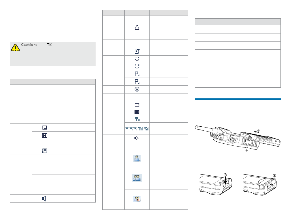
LCD Icon
Icon Name Icon Radio Status
DTMF
Keypad Icon
GPS Icon
Battery
Power Icon
TX Power
Icon
Accessory
Icon
Work Ord er
Icon
Operation
Mode Icon
Monitor Icon
4
The DTMF key pad is
active.
The GPS feature is
enabled, and valid
GPS data is received.
The GPS feature is
enable d, but no valid
GPS data is received.
More bars indicate
more bat tery powe r.
Low TX power for the
curre nt channel.
High TX p ower for the
curre nt channel.
An acc essory i s
connected.
One or mo re new work
orders are received.
Direc t Mode
Operation: Under
DM
this mod e, radios can
communicate with
each other directly.
Repeater Mode
Operation: Under
RM
this mod e, radios
communicate wit h each
other via a repeater.
The Mon itor feature is
active.
Icon Name Icon Radio Status
Emergency
Icon
Roam Icon
Scrambler/
Encrypt Icon
Scan Icon
VOX Icon
Misse d Call
Icon
Message
Icon
RSSI Icon
Speaker
Icon
LQO Icon
Call/Contact
Icon
The radi o is in
emergency state
(except for silent
emergency type) or
an emergency call is
received.
The radi o is roaming.
The Scrambler/Encrypt
feature i s active.
The radi o is scanning.
The radi o stays on a
non-priority channel.
The radi o stays on
Priority Channel 1.
The radi o stays on
Prior ity Channel 2.
The VOX feature is
enabled.
Missed call(s).
New message/unre ad
message.
Inbox is full.
No signal.
More bars indicate
better signal strength.
The speaker is
unmuted.
The LQO fea ture is
active.
●
Indicates a private
call in progress.
●
Indicates a private
contact in the
contact list.
●
Indicates a group
call in progress.
●
Indicates a group
contact in the
contact list.
●
Indicates an all call
in progress.
●
Indicates an all
call contact in the
contact list.
LED Indicator
LED Indication Radio Status
The LED in dicator
ashes g reen.
The LED in dicator
glows green.
The LED in dicator
glows red.
The LED in dicator
ashes o range slow ly.
The LED in dicator
ashes orange rapidly.
The LED in dicator
glows orange.
Powerin g on
Receiving
Transmitting
Scanning or roaming
Emergency
Call hung. During a call,
you can ho ld down the
PTT key to talk to th e other
party before the call hang
time expires.
Before Use
Attaching the Battery
1. Align the battery slots with the guide rails on the
radio as ① shows, and push the battery as
shows.
2. Open the battery latch and hold it down until the
metal lock goes into the battery housing completely
as ③ shows.
②
3. Push the battery until it is fully tted into the slot,
and then release the battery latch as ④ shows.
Note: To remove the battery, please power
off the radio first. Then open the battery
latch, and slide the battery out while
holding down the battery latch.
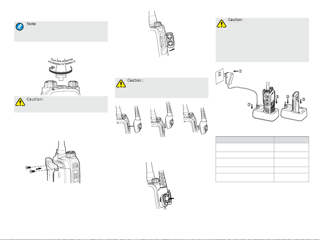
Attaching the Antenna
Caution: Do not hold the radio by its
antenna, otherwise the performance and
lifespan of the antenna will be reduced.
Attaching the Belt Clip
1. Loosen the screws from the back of the radio.
2. Align the screw holes on the belt clip with those on
the radio’s back, and then tighten the screws.
Attaching the Accessories
1. Open the accessory connector cover as shown
below.
2. Align the accessory (such as an audio accessory,
or a programming cable) plug with the accessory
connector.
Caution:Do not scrape the silicone rubber
surrounding the accessory connector screw
hole, in order to ensure the waterproof
performance of the radio.
√
3. Tighten the screw on the accessory plug.
× ×
Charging the Battery
Caution:
●
Use the charger specified by the
Company to charge the battery.
●
Make sure the radio is powered off
before charging. Read the Safety
Information Booklet in advance to get
necessary safety information.
●
Charge a new battery for at least 5 hours
before initial use for best performance.
Charge the Radio
(with battery attached)
Charge the Battery
Charging Status Indication (on charger):
LED Indication Charging Status
The LED In dicator f lashes red
slo wly.
The LED In dicator gl ows red. Charging
The LED In dicator gl ows
orange.
The LED Indicator glows green. Fully charged
The LED In dicator f lashes red
rap idl y.
Standby (no load)
90% charged
Charging failed
Checking the Battery Power
You can chec k the curre nt batter y power by hold ing
down the p rogrammed Battery Power Indicator key
preset by your dealer. And release the key to exit.
Battery power indications and alert tone are listed
below:
5
LED Indication/Tone Icon
The LED In dicator gl ows
green.
The LED In dicator gl ows
orange.
The LED In dicator gl ows
red.
The LED In dicator gl ows
red and an a lert tone
sounds.
The bat tery runs low.
Please recharge or
replac e the battery for
proper radio operation
Basic Operation
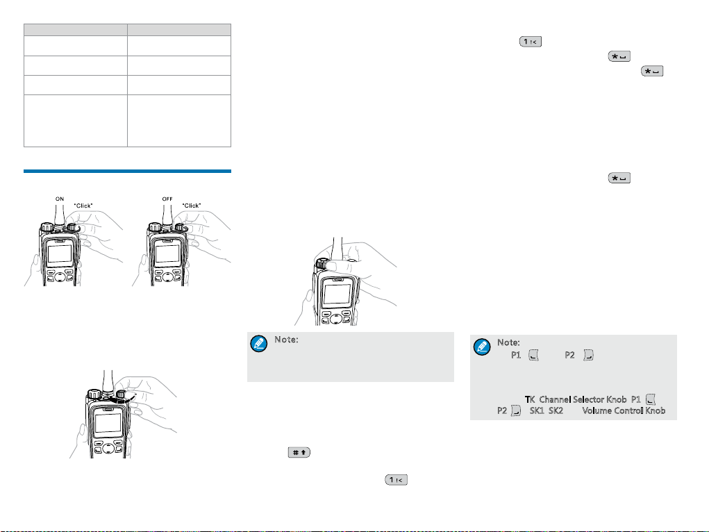
Turning the Radio On/Off
Adjusting the Volume
You can adjust t he volume of ou tput voice, a lert tone
and channel noticati on to ne by rotating the Volume
Control Knob. For other tones, the vol ume will be
cong ured by the dealer.
6
Selecting a Zone
A zone is a gr oup of channe ls with the s ame proper ty,
which c an facilit ate convenie nt manageme nt over
the channels. The radio supports 64 zon es, each of
which c onsists of up to 16 channels. Your dealer can
program the zone for y our specic needs.
You can selec t a zone through any of the fol lowing
ways:
●
Menu: Go to “Menu -> Zone”, press the Up/Down
key to select an appropriate zone, and then press
the OK key to switch to the selected zone.
●
Shortcut key: You can toggle to the appropriate
zone by pressing the programmed Zone Up or
Zone Down key preset by your dealer.
Selecting a Channel
Note: If the Channel Notify feature is
enabled by your dealer, the radio will
announce the channel number upon
channel switching.
Inputting via Keypad
You can input alias, call nu mbers and me ssages vi a
the keypad o f the radio. In t he editing m ode, you may
do as foll ows.
●
Press to switch the text input methods
between alphabetic mode and numeric mode
●
In the alphabetic mode, press to input the
special characters. But in the numeric mode,
pressing will input the numeric digit 1
●
In the alphabetic mode, press to input the
space. But in the numeric mode, pressing will
input the special characters
Locking and Unlocking the Keypad
When the keypad is not in use, you can lock the
keypad to prevent accide ntal keypad op eration. T he
follow ing methods a re available f or you to lock o r
unlock the keypad:
●
Key Combination: Press “OK+ ” to lock or
unlock the keypad.
●
Shortcut key: Press the programmed Keypad Lock
key to lock or unlock the keypad.
●
Menu: Go to “Menu -> Settings -> Radio Set ->
Keypad Lock” and then select “Enable” or “Disable”.
»
Enable: The keypad will be locked automatically
if no operation is made within the preset time
period. After the “Enable” option is selected, you
can press the Up/Down key to set the Keypad
Auto Lock Delay Time.
»
Disable: The keypad will not be locked
automatically.
Note: All keys on the front panel except
P1 ( ) and P2 ( ) will be locked by
for
default. Moreover, you can go to “Settings
-> Radio Settings -> Select Button Lock”
to configure the following lockable keys or
knobs:
TK, Channel Selector Knob, P1( )、
P2( ), SK1, SK2 and Volume Control Knob.
Managing the Contact
Contact management allows you to view, edit, delete
or add co ntacts.
Contact List
The contact list is u sed to save pri vate call co ntact,
group call contac t, and all call contact i nformati on
such as c all alias, call type and call ID.
●
Go to the “Menu -> Contact -> Contact List” menu
to access the contact list.
●
Press the programmed Contact List key to access
the contact list.
In the “C ontact Lis t” menu, you c an view, edit o r delete
the pri vate contac t. You can send to a pr ivate call
contact the follo wing commands: Aler t Call, Radi o
Check, Remote Monitor, Radio Enable or Radio
Disabl e. Please refer to the Feature Descript ion and
Operation Manua l along with t he produc t for details.
Favorite Contact
Favorite C ontact is used to save the frequently u sed
contacts.
●
Go to the “Menu -> Contact -> Favorite Contact”
menu to access the favorite contact list.
●
Press the programmed Favorite Contact List key
to access the favorite contact list.
In the favo rite cont act list, you c an view, edit or delete
the favor ite contacts. You can send to a favorite
contact the follo wing commands: Aler t Call, Radi o
Check, Remote Monitor, Radio Enable or Radio
Disabl e. Please refer to the Feature Descript ion and
Operation Manua l along with t he produc t for details.
New Contact
New Cont act is used t o add a new cont act to the
contact list.
Go to the “ Menu -> Contact -> New C ontact ” menu
to acce ss the relevant screen. In put the number and
alias of a new contact a nd save it to the p rivate con tact
list.
Note:
●
The number and alias of a new contact
must be unique.
●
You can also save the numbers from the
Call Logs into the contact list.
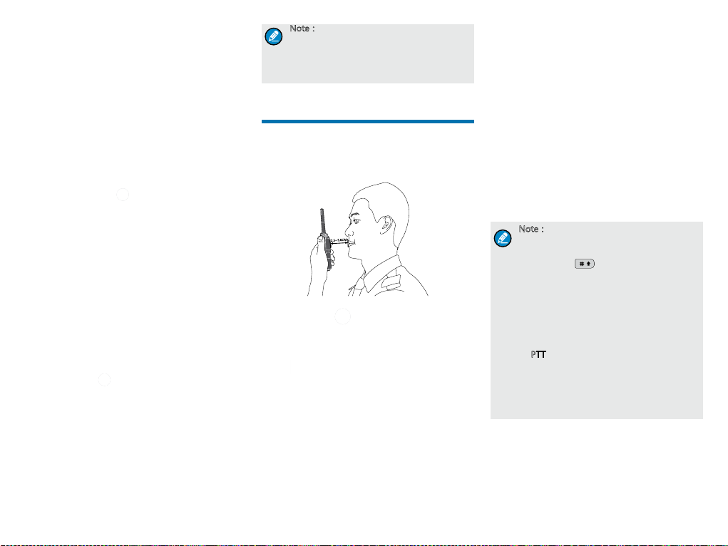
Call Services
After t he radio is po wered on, you c an make and
receive calls. To ensure o ptimal volume of the
recei ving radio, ke ep the microphone abo ut 2.5 to 5
centim eters away fr om your mouth w hen transmitting.
M
0C
.
5
~
5
.
2
Private Call
Initiating a Private Call
When ini tiating a pr ivate call, t he radio wil l display the
. You can make a private call th rough the
icon
following ways:
Preset Contact
You may request your dealer to p reset a regul ar
private c all cont act for each d igital cha nnel.
In the hom e screen, hold down the PTT key to initiate
a private c all to the pr ivate cont act preset fo r the
curre nt channel.
Contact List
1. Go to “Menu -> Contact -> Contact List”.
2. U se th e Up/Down key to select an appropriate
contact.
3. Hold down the PTT key to initiate a private call.
Call Logs
1. Go to “Menu -> Call Logs -> Outgoing/Incoming/
Missed”.
2. U se th e Up/Down key to select an appropriate
contact.
3. Hold down the PTT key to initiate a private call.
Manual Dial
1. Go to “Menu -> Contact -> Manual Dial”.
2. Input the private call number using the numeric
keypad.
3. Hold down the PTT key to initiate a private call.
Note:
●
If both the Private Call Manual Dial and
Group Call Manual Dial are available, you
can press
two dialing methods, and the radio will
display the call type (Private ID/ Group
ID).
●
If the Default Numeric Key Selection
feature is enabled by your dealer, you
can enter a private call number in the
home screen, and then hold down the
PTT key to initiate a private call. However,
if the DTMF keypad is enabled, the
number entered in the home scr
phone number. You can dial the private
call number through the “Manual Dial”
menu only.
to switch between the
een is a
Receiving and Responding to a Private Call
When you r eceive a private call, th e radio will d isplay
the ico n
operation.
, then you can listen without any
7
 Loading...