

Hytera DS-6210U5C4 Owner's Manual

DS-6210U5C4 Base Station
Owner's Manual
Version: V00
Release Date:Oct., 2012


Owner's Manual
Contents
Contents
1. Checking Items in the Package .......................................................................................................... 8
2. Product Controls .................................................................................................................................. 9
2.1 Interface Units of 4-carrier Base Station .......................................................................................... 9
2.1.1 Antenna Connector ............................................................................................................... 10
2.1.2 EIB ........................................................................................................................................ 10
2.1.3 Power Supply Inter face ........................................................................................................ 12
2.2 Cartridge ......................................................................................................................................... 13
2.3 Channel Unit (CHU) ........................................................................................................................ 13
2.3.1 Function ................................................................................................................................ 13
2.3.2 Front Panel ........................................................................................................................... 14
2.3.3 LED Indicator ........................................................................................................................ 15
2.4 Base Station Controlle r Unit (BSCU).............................................................................................. 16
2.4.1 Function ................................................................................................................................ 16
2.4.2 Front Panel ........................................................................................................................... 17
2.4.3 LED Indicator ........................................................................................................................ 18
2.5 Power Supply Unit (PSU) ............................................................................................................... 19
2.5.1 Function ................................................................................................................................ 19
2.5.2 Front Panel ........................................................................................................................... 20
2.5.3 LED Indicator ........................................................................................................................ 21
2.6 Interconnect Backbo ar d ( I CB) ........................................................................................................ 22
2.6.1 Front View ............................................................................................................................ 22
2.6.2 Rear View ............................................................................................................................. 23
2.7 FAN ................................................................................................................................................. 25
2.7.1 Front Panel ........................................................................................................................... 25
2.7.2 LED Indicator ........................................................................................................................ 25
2.7.3 Rear Panel............................................................................................................................ 26
2.8 Divider Unit (DIU) ............................................................................................................................ 27
2.8.1 Function ................................................................................................................................ 27
2.8.2 Front Panel ........................................................................................................................... 27
2.8.3 Rear Panel............................................................................................................................ 28
2.9 Router ............................................................................................................................................. 29
i
2.9.1 Function ................................................................................................................................ 29
2.9.2 Front Panel ........................................................................................................................... 29
2.9.3 Rear Panel............................................................................................................................ 30
2.9.4 LED Indicator ........................................................................................................................ 30

Contents
Owner's Manual
2.10 IP-E1 ............................................................................................................................................. 31
2.10.1 Front Panel ......................................................................................................................... 31
2.10.2 LED Indicator ...................................................................................................................... 32
2.10.3 Rear Panel.......................................................................................................................... 33
2.11 Combiner (COM) .......................................................................................................................... 33
2.11.1 Function .............................................................................................................................. 34
2.1 1. 2 Rear Panel .......................................................................................................................... 34
3. Installation ........................................................................................................................................... 36
3.1 Cable Layout ................................................................................................................................... 36
3.2 Safety Information........................................................................................................................... 36
3.2.1 Power Supply ....................................................................................................................... 37
3.2.2 Working at He ights ............................................................................................................... 37
3.3 Installation Preparation ................................................................................................................... 37
3.3.1 Technical Files ...................................................................................................................... 37
3.3.2 Personnel ............................................................................................................................. 38
3.3.3 Tools ..................................................................................................................................... 38
3.4 Unpacking Inspection ..................................................................................................................... 39
3.4.1 Check before Unpac king ...................................................................................................... 39
3.4.2 Unpacking Wooden Case..................................................................................................... 39
3.4.3 Unpacking Cartons ............................................................................................................... 40
3.4.4 Inspections ........................................................................................................................... 41
3.5 Installing the Cabinet ...................................................................................................................... 41
3.5.1 Determine the Installation Position ...................................................................................... 41
3.5.2 Installing the Cabine t ............................................................................................................ 42
3.6 Installing Modules into the Cabinet ................................................................................................ 43
3.6.1 Module Layout ...................................................................................................................... 43
3.6.2 Installation Procedures ......................................................................................................... 43
3.7 Installing Cables ............................................................................................................................. 47
3.7.1 Equipment Status ................................................................................................................. 47
3.7.2 Cables .................................................................................................................................. 47
3.8 Examination after Installation ......................................................................................................... 49
3.8.1 Equipment Status ................................................................................................................. 49
3.8.2 Examining the Cabi net ......................................................................................................... 49
3.8.3 Examining Cables ................................................................................................................ 49
3.8.4 Power On and Exam ination ................................................................................................. 50
3.8.5 Environment Exa minat ion .................................................................................................... 50
4. Basic Operations ................................................................................................................................ 52
ii

Owner's Manual
Contents
4.1 Powering on .................................................................................................................................... 52
4.2 Powering off .................................................................................................................................... 52
5. Troublesho ot ing ................................................................................................................................. 53
6. Routine Maintena nce ......................................................................................................................... 54
6.1 Purpose........................................................................................................................................... 54
6.2 Tasks .............................................................................................................................................. 54
A Abbreviations ...................................................................................................................................... 55
iii

Figures
Owner's Manual
Figures
Figure 2-1 Interface Units of 4-car r ier Base Station .................................................................................. 9
Figure 2-2 Antenna Connector of 4-c arr ier Base Sta tion ......................................................................... 10
Figure 2-3 EIB of 4-car rier Base Station ................................................................................................... 11
Figure 2-4 Power Supply Inter fac e of 4-carrier Base Station .................................................................. 12
Figure 2-5 Full Configurati on for MC ........................................................................................................ 13
Figure 2-6 Logical Architecture of CHU ................................................................................................... 13
Figure 2-7 Front Panel of C HU ................................................................................................................ 14
Figure 2-8 Logic Architecture of BSCU .................................................................................................... 16
Figure 2-9 Front Panel of BS C U .............................................................................................................. 17
Figure 2-10 Front Panel o f PS U ............................................................................................................... 21
Figure 2-11 Front View of ICB .................................................................................................................. 23
Figure 2-12 Rear View of ICB .................................................................................................................. 24
Figure 2-13 Front Panel o f FAN ............................................................................................................... 25
Figure 2-14 Rear Panel of FAN ................................................................................................................ 26
Figure 2-15 Logical Diagram of DIU ........................................................................................................ 27
Figure 2-16 Front Panel o f DIU ................................................................................................................ 27
Figure 2-17 Rear Panel of DIU................................................................................................................. 28
Figure 2-18 Front Panel o f Router ........................................................................................................... 29
Figure 2-19 Rear Panel of Rout er ............................................................................................................ 30
Figure 2-20 Front Panel o f I P-E1 ............................................................................................................. 32
Figure 2-21 Rear Panel of IP-E1 .............................................................................................................. 33
Figure 2-22 Logical Diagram of 4-port Combiner .................................................................................... 34
Figure 2-23 Rear Panel of COM .............................................................................................................. 34
Figure 3-1 Cable Layout ........................................................................................................................... 36
Figure 3-2 Removing the Cover ............................................................................................................... 40
Figure 3-3 Layout of holes for a Si ngle Cabinet ...................................................................................... 41
Figure 3-4 Layout of holes for Co m bi ned Cabinet ................................................................................... 42
Figure 3-5 Tighte ning the Bolt .................................................................................................................. 42
Figure 3-6 of Module Layout .................................................................................................................... 43
Figure 3-7 Opening the C abi net Door ...................................................................................................... 44
Figure 3-8 Disassembling the Side Door ................................................................................................. 44
Figure 3-9 Loosening the Ej ect or ............................................................................................................. 45
Figure 3-10 Installing the BSCU............................................................................................................... 45
Figure 3-11 Installing the FAN .................................................................................................................. 46
Figure 3-12 Removing the FAN................................................................................................................ 46
iv

Owner's Manual
Figures
Figure 3-13 Installing the Divider Unit ...................................................................................................... 46
Figure 3-14 Installing the Combiner Unit ................................................................................................. 47
Figure 3-15 Cable Diagram ...................................................................................................................... 47
Figure 3-16 External Cable Connection ................................................................................................... 48
v

Tables
Owner's Manual
Tables
Figure 1-1 Packing List .............................................................................................................................. 8
Table 2-1 Descriptions on Interface Un its of 4-carrier Base Station ........................................................ 10
Table 2-2 Descriptions on Antenna Connector of 4-carrier Base Stat ion ................................................ 10
Table 2-3 Descriptions on EIB of 4-carrier Base Station .......................................................................... 11
Table 2-4 Descriptions on Power Supply Inter face of 4-carrier Base Station .......................................... 12
Table 2-5 Description on Front Panel of CHU .......................................................................................... 15
Table 2-6 Descriptions on CHU Indicat or s ............................................................................................... 16
Table 2-7 Descriptions on Front Panel of BS CU ...................................................................................... 18
Table 2-8 Descriptions on BSCU Indicator s ............................................................................................. 19
Table 2-9 Descriptions on PSU ................................................................................................................ 20
Table 2-10 Descriptions on Front Pa nel of PSU ...................................................................................... 21
Table 2-1 1 D escriptions on PSU Indicators .............................................................................................. 22
Table 2-12 Descriptions on Front Int er fa c es of ICB ................................................................................. 23
Table 2-13 Descriptions on Rear Interfaces of ICB.................................................................................. 24
Table 2-14 DIP Switch Settings for ICB ................................................................................................... 25
Table 2-15 Descriptions on FAN Indicators .............................................................................................. 26
Table 2-16 Descriptions on Rear Pan el of FAN ....................................................................................... 26
Table 2-17 DIP Switch Settings for FAN .................................................................................................. 27
Table 2-18 Descriptions on Front Pa nel of DIU ....................................................................................... 28
Table 2-19 Descriptions on Rear Pan el of DIU ........................................................................................ 28
Table 2-20 DIU Address Settings ............................................................................................................. 29
Table 2-21 Descriptions on Front Pa nel of Router ................................................................................... 29
Table 2-22 Descriptions on Rear Pan el of Router ................................................................................... 30
Table 2-23 Descriptions on Router I ndicators .......................................................................................... 31
Table 2-24 Descriptions on IP-E1 Ind icat or s ............................................................................................ 32
Table 2-25 Descriptions on Rear Pan el of IP-E1 ..................................................................................... 33
Table 2-26 Descriptions on Rear Pan el of COM ...................................................................................... 35
Table 3-1 Technical Files .......................................................................................................................... 38
Table 3-2 Tools and Meter ........................................................................................................................ 38
Table 3-3 Cables Description ................................................................................................................... 48
Table 3-4 Descriptions on the interface o f external cable connection ..................................................... 48
Table 3-5 Checklist of Cabinet Installation ............................................................................................... 49
Table 3-6 Checklist of Cables ................................................................................................................... 50
Table 3-7 Checklist of Power Situation .................................................................................................... 50
Table 3-8 Checklist of Environment on S ite ............................................................................................. 51
vi

Owner's Manual
Tables
Table 5-1 Troubleshooti ng ........................................................................................................................ 53
vii

Checking Items in the Package
Owner's Manual
1. Checking Items in the Package
No. Item Qty. (PCS)
1 Base Station Controller U nit (BSCU) 1
2 Channel Unit (C HU) 4
3 Power Support Unit (PS U) 2
4 Fan Unit 1
5 Divider Unit (DIU) 1
6 Combiner Unit (COM) 1
7 Cabinet Kit 1
Figure 1-1 Packing List
8
Owner's Manual
Product Controls
It contains the GPS antenna connector, RX antenna
2. Product Controls
Note
Devices except for CHU, BS CU, PSU and ICB are optional.
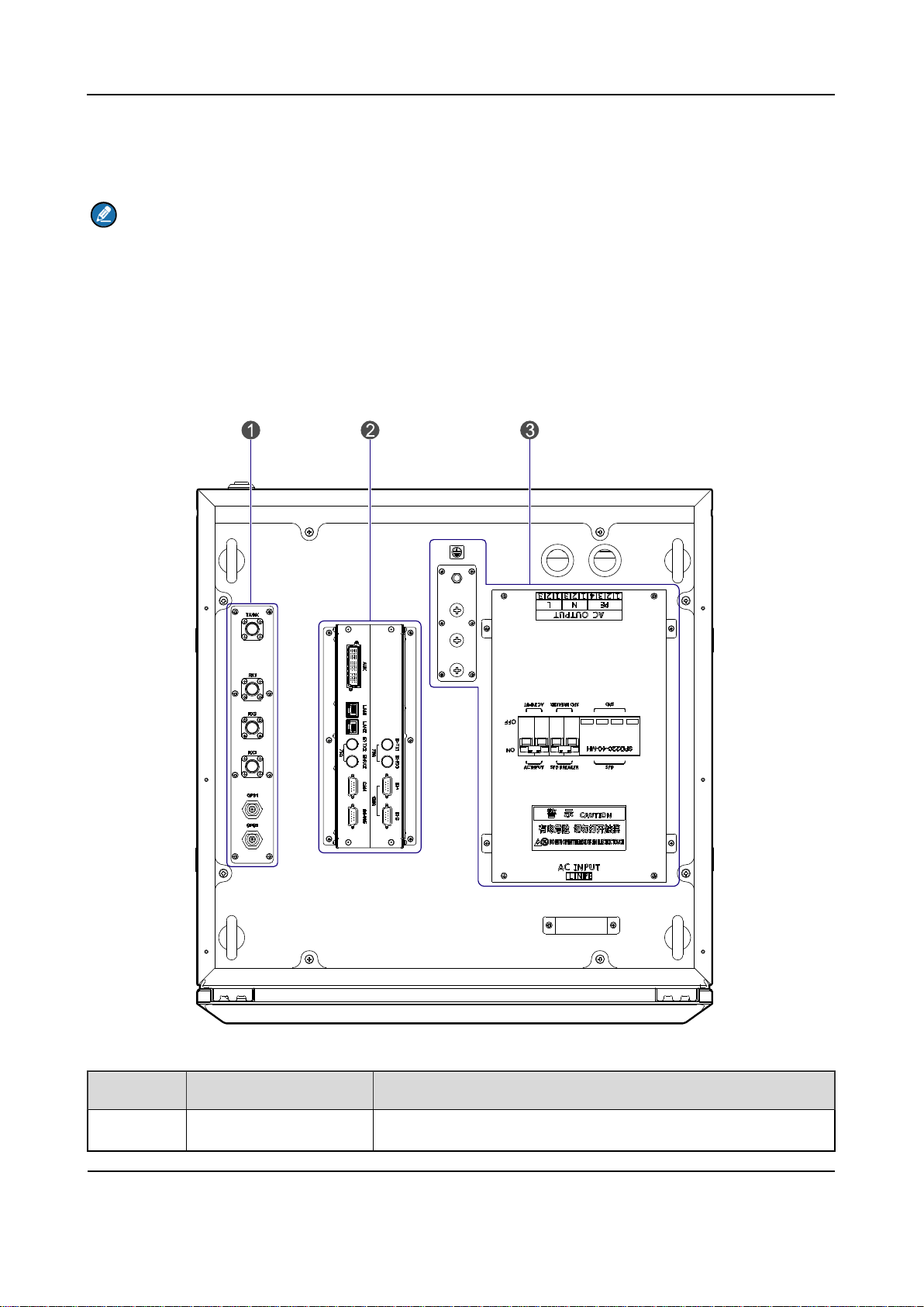
2.1 Interface Units of 4-carrier Base Station
The interface units on the top of the cabinet consist of the antenna connector, extended interface
board (EIB) and power su pply int erface. See Figure 2-1.
Figure 2-1 Interface Un its of 4-car r ier Base Station
No. Name Description
1 Antenna Connector
9
Product Controls
Owner's Manual
It contains the core network interface, cabinet expansion
TX Antenna
RX Antenna
GPS Antenna
No. Name Description
connector and TX antenna connector.
2 EIB
interface and monitor inter face.
3 Power Supply Interface /
Table 2-1 Description s on Interface Units of 4-carri er Base Station
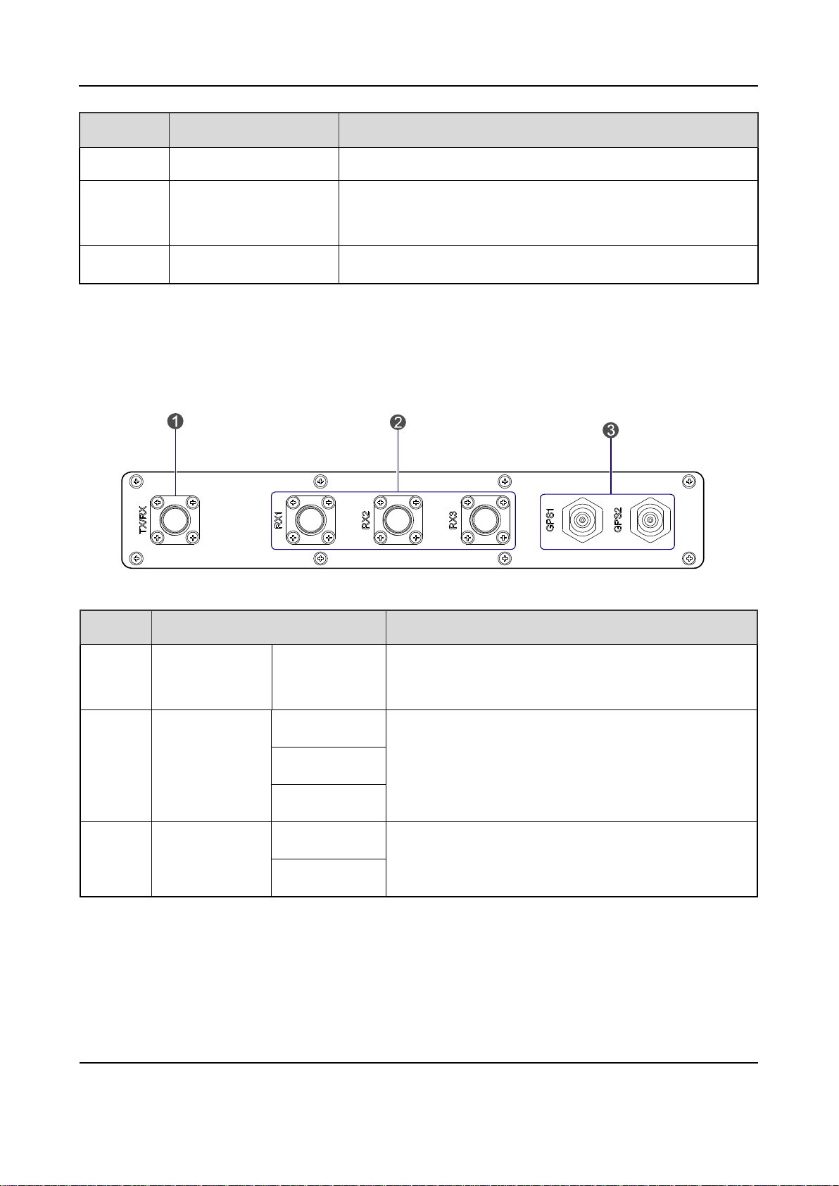
2.1.1 Antenna Connector
The antenna connector is illustrated below .
Figure 2-2 Antenna Conn ec t or of 4-c arr ier Base Sta tion
No. Name Description
1
Connector
2
Connector
3
Connector
Table 2-2 Description s on Antenna Connector of 4-carrier Base Station
TX/RX N-connector (female)
RX1
RX2
RX3
GPS1
GPS2
N-connector (female)
N-connector (female)
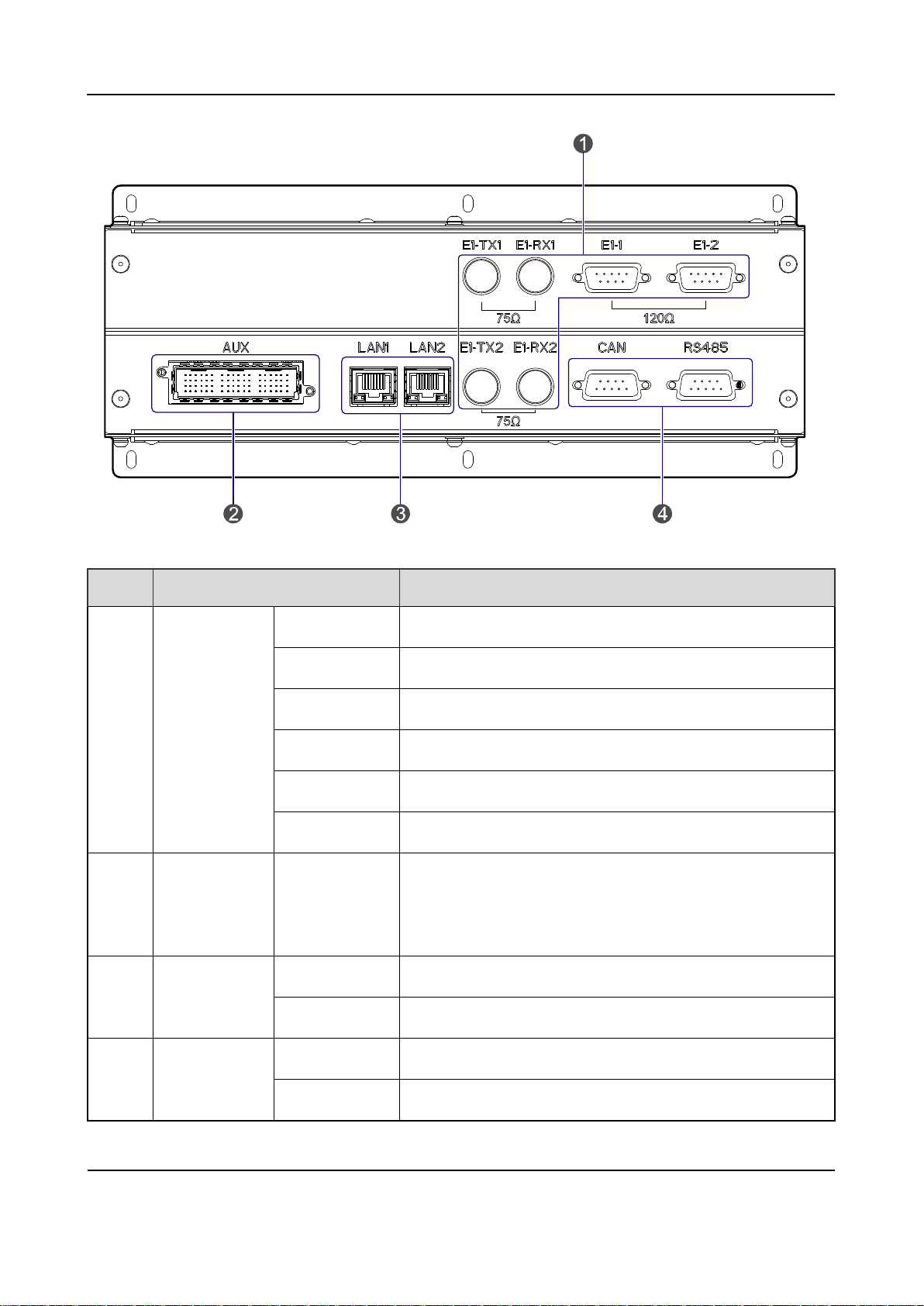
2.1.2 EIB
The EIB is illustrated below.
10
Owner's Manual
Product Controls
Figure 2-3 EIB of 4-c arri er Base Station
No. Name Description
E1-TX1 BNC-connector (female)
E1-RX1 BNC-connector (female)
E1-1 DB9-connector (female)
1 E1 Interface
E1-2 DB9-connector (female)
E1-TX2 BNC-connector (female)
E1-RX2 BNC-connector (female)
Cabinet
2
Expansion
AUX Dedicated 72-pin interface
Interface
Ethernet
LAN1 RJ-45 connector
3
Interface
LAN2 RJ-45 connector
4
11
Monitor
Interface
CAN DB9-connector (female)
RS485 DB9-connector (female)
Table 2-3 Description s on EIB of 4-carrier Base Station
Product Controls
Owner's Manual
Core Network Interface
The core network interface contains the 4-path E1 interface and 2-path Et hernet interface.
Cabinet Expansion Interface
The cabinet expansion interface has 8-path extended signals. It is applied to connect to four
interconnect relay units o f another cabinet, in case of inter connecting two cabinet s.
Monitor Interface
The monitor interface inc l udes one CAN-BUS interface and one RS485 interface.
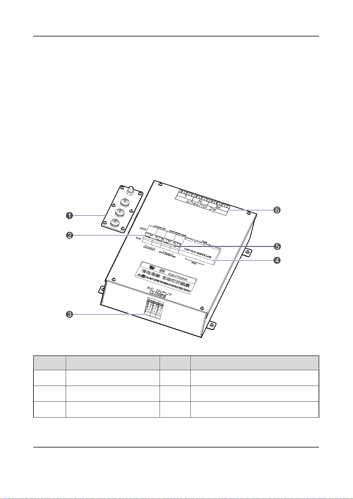
2.1.3 Power Supply Interface
The power supply interfac e is i ll ust r at ed below.
No. Name No. Name
12
Figure 2-4 Power Supp ly Int er fac e of 4-carrier Base Station
1 Ground Bar 2 AC Input Breaker
3 AC Input Terminal 4 Surge Protection Device (SPD)
5 SPD Breaker 6 AC Output Terminal
Table 2-4 Description s on Power Supply Interface o f 4-carrier Base Station
Owner's Manual
Product Controls
C
H
U
02
P
S
U
08
P
S
U
07
B
S
C
U
06
C
H
U
01
B
S
C
U
05
C
H
U
04
C
H
U
03
RX Antenna 3
PA
TX Excitation
Unit
Baseband Signal Processing Unit
Power
Diversity Receiver
TX Antenna
ICB
RX Antenna 2
RX Antenna 1
2.2 Cartridge
In accordance with the IEC60297 standard, the cartridge is 19 inches in width and 7U in height. Each
cartridge can accommodate four CHUs, two BSCUs and two PSUs
The slot 5 and slot 6 of the main chass is are available for the BSCU. See Figure 2-5.
Figure 2-5 Full Configurat i on for MC
.
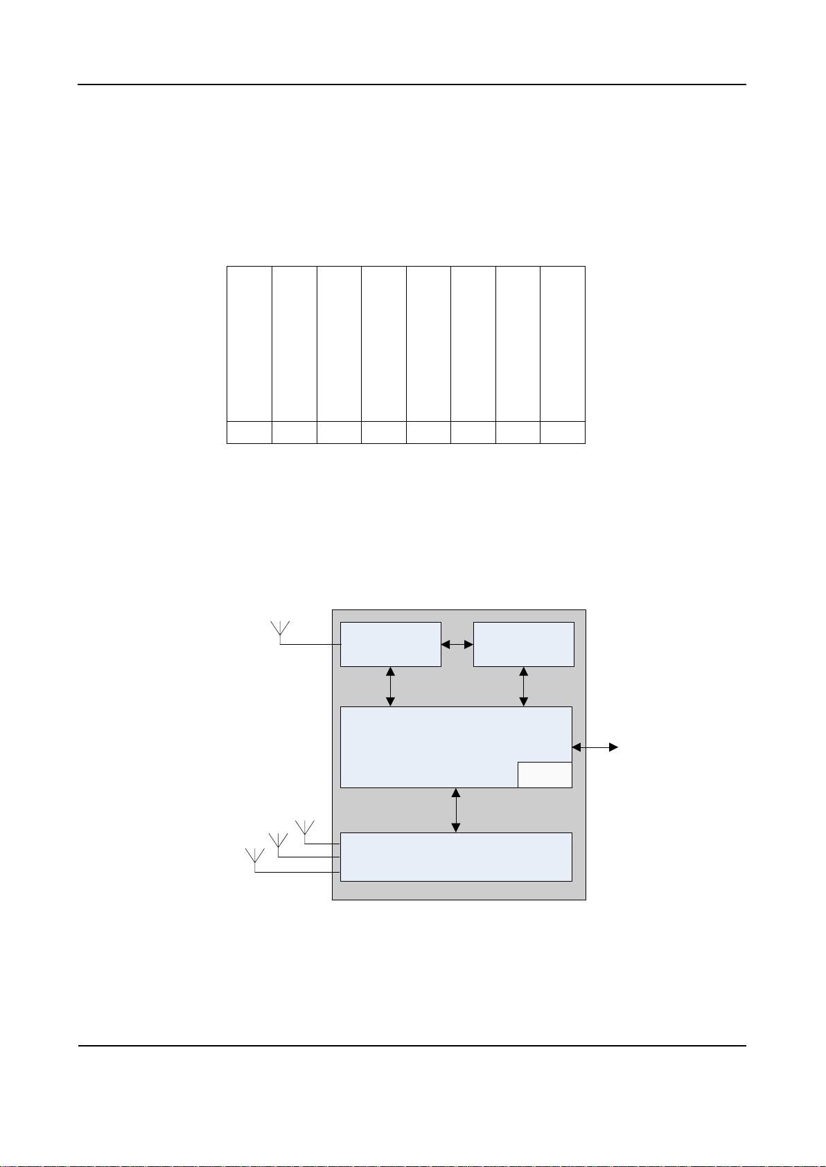
2.3 Channel Unit (CHU)
The CHU logically includes power amplification, TX excitation unit, baseband signal processing unit
and diversity receiver. See Figure 2-6.
2.3.1 Function
The CHU processes and converts protocols on the physical layer and data link layer of the DMR air
interface. Physically, it consists o f channe l contr ol boar d (CHB), TX boar d (TX B) and RX board (RX B).
13
Figure 2-6 Logical Arch itecture of CHU
Product Controls
Owner's Manual
CHB: capable of signaling processing, channel encoding/decoding, interleaving and de-interleaving,
modulation/demodulation, RF signal loop-back test and fail-soft.
TXB: capable of modulation, upward frequency conversion, filtering and D/A conversion from carrier
baseband signal to RF signal, as w ell as the downlink signal ampl ification.
RXB: capable of filtering, demodulation, downward frequency conversion, AGC and A/D conversion
from three-path carrier signal to baseband signal, as well as uplink signal a m plification.
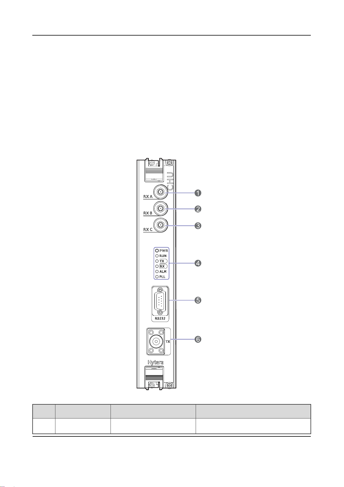
2.3.2 Front Panel
The front panel of the CHU is illustr ated below.
No. Name Description Remarks
1 RXA Diversity RX antenna inpu t SMA-connector (female)
14
Figure 2-7 Front Pane l of CHU

Owner's Manual
Product Controls
No data is present on the
An alarm is given for PLL
No. Name Description Remarks
2 RXB RX antenna input SMA-connector (female)
3 RXC Diversity RX antenna input SMA-connector (female)
4 LEDs LED indicator /
5 RS232 Debug interface DB9-connector (female)
6 TX Transmission N-connector (female)
Table 2-5 Description o n Front Panel of CHU
2.3.3 LED Indicator
The CHU indicators are described in Table 2-6.
LED
Indicator
PWR Green
RUN Green
TX Green
RX Green
Color Status Description (in work in g mode) Descriptio n (i n sl eep mode)
On The CHU is powered on. The CHU is powered on.
Off The CHU is powered off. The CHU is powered off.
Flashing The CHU runs properly. \
Off The CHU does not run properly. The CHU is in sleep mode.
On
Off
On
Off
Data is present on downlink slot
2 of the CHU.
Data is present on downlink slot
1 of the CHU.
Data is present on the uplink of
the CHU.
No data is present on the uplink
of the CHU.
\
The CHU is in sleep mode.
Data is present on the uplink of
the CHU.
uplink of the CHU.
ALM Red
PLL Red On An alarm is given for PLL unlock.
15
On The CHU software is faulty. The CHU software is faulty .
Off The CHU runs properly. The CHU runs properly.
Product Controls
Owner's Manual
BSCU-GPSB
GPS Board
BSCU-MCB
Main Control Board
Synchronizing Buffer
Ethernet Switch
RS232
MPU
Micro
Processor Unit
Power
Supply
CLK,CNT
LAN1
LAN11
CAN
...
RS-485
DC-IN
BSCU ICB
GPS
RS232
VGA
USB
LED
Indicator
Color Status Description (in work in g mode) Descriptio n (i n sl eep mode)
unlock.
Off The CHU runs properly. The CHU runs properly.
Table 2-6 Description s on CHU Indicators
Note
In sleep mode, the CHU can receive inbound data. However, if the downlink channel is in use, the
CHU will turn to operation mode; if the downlink channel is released, the CHU will turn to sleep
mode.
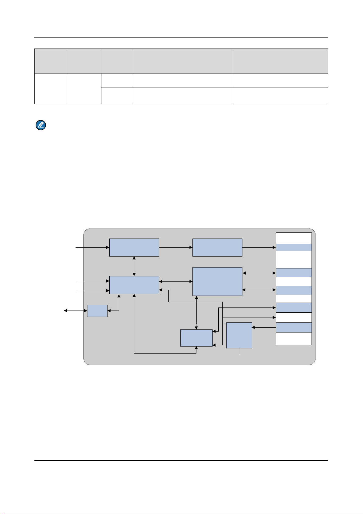
2.4 Base Station Controller Unit (BSCU)
The BSCU logically consists of GPS board, main control board, synchronizing buffer, Ethernet switch,
micro processor unit and power supply. See Figure 2-8.
2.4.1 Function
The BSCU is to manage the w ireless link r esour ces within t he cov erage and al locate th e m for diff erent
call services.
16
Figure 2-8 Logic Architecture of BSCU

Owner's Manual
Product Controls
2.4.2 Front Panel
The front panel of the BSCU is ill ust r at ed below.
Figure 2-9 Front Pane l of BSCU
No. Name Qty. Description Description
Video
1
2
3
17
graphics
array
USB
Interface
RS232
Interface
1 For debugging DB15-connector (female)
4 For debugging A-connector (female)
1 For debugging DB9-connector (male)
 Loading...