

Hytera ACCESSNET-T IP DIB-R5 flexibleTx Digital Integrated Base Station Operation Manual

ACCESSNET®-T IP
DIB-R5 flexibleTx
Digital Integrated Base Station
Operation Manual
90DIBR5flexibleTxOM02 - 1.2© 2016 Hytera Mobilfunk GmbH

DIB-R5 flexibleTx
Hytera Mobilfunk GmbH
Fritz-Hahne-Straße 7
31848 Bad Münder
Germany
Telephone: +49 (0)5042 / 998-0
Fax: +49 (0)5042 / 998-105
E-mail: info@hytera.de
Internet: www.hytera-mobilfunk.com
Read the instructions thoroughly prior to performing any tasks!
Keep these instructions for reference.
Subject to change without notice. Data without tolerance limits is not binding.
ACCESSNET is a registered trademark of Hytera Mobilfunk GmbH. HYT and Hytera are registered trademarks of Hytera Communications Corporation Limited.
2 Operation Manual 90DIBR5flexibleTxOM02 - 1.2

DIB-R5 flexibleTx
1 Notes on the document.................................................................................................. 7
1.1 Objectives of the document........................................................................................... 7
1.2 Intended audience of the document............................................................................. 7
1.3 Qualification of the personnel....................................................................................... 7
1.4 Reading and navigation aids in the document ........................................................... 8
1.5 Figures and special notations used.............................................................................. 8
1.5.1 Figures used..................................................................................................................... 8
1.5.2 Special notations.............................................................................................................. 8
1.5.2.1 Operating procedures....................................................................................................... 9
1.5.2.2 Safety instructions used.................................................................................................... 9
1.5.2.3 General instructions used............................................................................................... 10
1.5.2.4 Text formatting used....................................................................................................... 10
1.6 History of changes....................................................................................................... 11
1.7 Further applicable documents.................................................................................... 11
1.8 Support information..................................................................................................... 12
2 Safety regulations......................................................................................................... 15
2.1 Safety instructions and declaration of conformity.................................................... 15
2.1.1 Safety instructions and declaration of conformity for North America.............................. 15
2.2 Intended use.................................................................................................................. 18
2.3 Safety measures........................................................................................................... 19
Table of contents
Table of contents
2.3.1 Authorized personnel...................................................................................................... 19
2.3.2 Electromagnetic compatibility......................................................................................... 20
2.3.2.1 Electromagnetic compatibility for North America............................................................ 20
2.3.3 Notes on the electrical system........................................................................................ 20
2.3.4 Hazardous substances................................................................................................... 21
2.3.4.1 Hazardous substances outside Europe.......................................................................... 21
2.3.5 Product disposal............................................................................................................. 21
2.3.5.1 Product disposal outside Europe.................................................................................... 21
2.4 Safety and responsibility............................................................................................. 21
2.5 Safety markings............................................................................................................ 22
2.5.1 Safety markings on the product...................................................................................... 22
2.5.2 Safety markings on transport boxes............................................................................... 22
2.5.2.1 Safety marking "Fragile"................................................................................................. 22
2.5.2.2 Safety marking "Transport Upright"................................................................................ 23
3Operation Manual 90DIBR5flexibleTxOM02 - 1.2

Table of contents
2.5.2.3 Safety marking "Keep dry".............................................................................................. 23
3.1 Characteristics of the DIB-R5...................................................................................... 31
3.2 Components.................................................................................................................. 32
3.2.1 Connection and control panel......................................................................................... 33
3.2.1.1 On/off switch................................................................................................................... 36
3.2.1.2 Connection panel............................................................................................................ 36
3.2.1.3 GNSS splitter.................................................................................................................. 38
3.2.2 VAC power supply............................................................................................................ 38
3.2.2.1 AC Power Distribution Module (APDM).......................................................................... 38
3.2.2.2 Power Supply Unit (PSU) including Power Supply Module (PSM)................................. 40
3.2.3 VDC power supply............................................................................................................ 42
3.2.4 Divider Unit (DIU)............................................................................................................ 44
3.2.4.1 Active Divider Unit (ADU)............................................................................................... 45
3.2.5 TETRA Channel Unit (CHU)........................................................................................... 46
3.2.6 Base Station Controller Unit (BSCU).............................................................................. 49
3.2.7 Fan unit........................................................................................................................... 53
3.2.8 Backplane....................................................................................................................... 55
3.3 Interfaces....................................................................................................................... 57
3.4 Wiring diagrams............................................................................................................ 57
3.4.1 Internal wiring................................................................................................................. 58
3.4.1.1 Internal wiring with four CHUs and external antenna coupling system........................... 58
3.4.2 Antenna configurations................................................................................................... 59
3.4.2.1 Antenna configuration with four CHUs and external antenna coupling system.............. 59
3.5 Redundancy options.................................................................................................... 60
3.5.1 Redundant main control channel (MCCH)...................................................................... 61
3.5.2 Carrier redundancy......................................................................................................... 61
3.5.3 Controller redundancy.................................................................................................... 61
3.5.4 Fallback operation.......................................................................................................... 61
3.5.5 Stand-alone operation.................................................................................................... 62
3.5.6 Redundant VAC power supply......................................................................................... 62
DIB-R5 flexibleTx
3 Product description...................................................................................................... 25
3.5.6.1 Redundant rectifier modules (Power Supply Module, PSM)........................................... 62
3.5.6.2 Redundant power supply lines........................................................................................ 63
3.5.7 Redundant connection to the transport network............................................................. 63
3.5.8 Redundant synchronization (GNSS, PTP)...................................................................... 63
3.6 Scope of delivery.......................................................................................................... 64
4 Operation....................................................................................................................... 65
4 Operation Manual 90DIBR5flexibleTxOM02 - 1.2

DIB-R5 flexibleTx
4.1 Safety measures and prerequisites............................................................................ 65
4.2 Switching on the DIB-R5 flexibleTx............................................................................ 66
4.3 Function tests and operational monitoring................................................................ 67
4.3.1 Work equipment for function tests.................................................................................. 68
4.3.2 Connecting the service computer................................................................................... 69
4.3.3 Checking operating states.............................................................................................. 70
4.3.3.1 Checking operating states (via LEDs)............................................................................ 70
4.3.3.2 Checking operating states (audible check)..................................................................... 70
4.3.3.3 Checking operating states (via NMC-511 FaultManager)............................................... 71
4.3.4 Checking the availability................................................................................................. 72
4.3.5 Checking standby carriers ‒ optional.............................................................................. 73
4.3.6 Function tests and GNSS operational monitoring........................................................... 74
4.3.6.1 Checking the installation site of the GNSS antenna....................................................... 74
4.3.6.2 GNSS operational monitoring (via NMC-511 FaultManager)......................................... 75
4.3.7 Function tests and PTP operational monitoring (optional).............................................. 76
4.3.7.1 PTP operational monitoring (via NMC-511 FaultManager)............................................. 76
4.3.8 Checking external antenna coupling systems................................................................ 77
5 Service interruption...................................................................................................... 79
5.1 Shutting down hardware components....................................................................... 79
5.2 Switching off the DIB-R5 flexibleTx............................................................................ 80
6 Recommissioning......................................................................................................... 81
7 Maintenance.................................................................................................................. 83
7.1 Maintenance tasks........................................................................................................ 83
7.2 Periodical visual inspections...................................................................................... 84
8 Troubleshooting........................................................................................................... 85
9 Index.............................................................................................................................. 89
Table of contents
5Operation Manual 90DIBR5flexibleTxOM02 - 1.2

Table of contents
DIB-R5 flexibleTx
6 Operation Manual 90DIBR5flexibleTxOM02 - 1.2

Qualification of the personnel
DIB-R5 flexibleTx
1 Notes on the document
1.1 Objectives of the document
Notes on the document
This chapter provides information on using the document. In addition, it specifies requirements that are absolutely necessary when working with the product.
The present document from Hytera Mobilfunk GmbH describes the procedures that are
required for the activities on and with the product:
n Operation
n Service interruption
n Recommissioning
n Maintenance
In this context, it describes the relevant safety regulations as well as the components and
operation of the product that is used in the ACCESSNET-T IP mobile radio system.
1.2 Intended audience of the document
The present document reverts to all the persons, who:
n operate an ACCESSNET-T IP TETRA mobile radio system,
n commission and decommission the product,
n maintain the product.
Each person commissioned with performing the tasks mentioned above with or on the
system must have read and understood the present document and the associated
accompanying documentation.
1.3 Qualification of the personnel
Only experts are permitted to perform the tasks described in the present document. The
experts must be authorized to perform these tasks.
Experts are persons, who:
n are trained and experienced in the corresponding field.
n are familiar with the applicable standards, regulations and provisions associated with
the corresponding task.
7Operation Manual 90DIBR5flexibleTxOM02 - 1.2

Notes on the document
Figures and special notations used > Special notations
1.4 Reading and navigation aids in the document
As reading and navigation aids, overview tables have been provided at the beginning of
the respective chapters in the present document. These are to provide the reader with an
overview of the tasks to be performed. In addition, they indicate the order in which the
tasks are to be performed. When you have completed a work step, always navigate to the
next work step via the overview table to ensure that the tasks are performed in the correct
order. The overview tables are useful for readers of the printed document (indication of
the corresponding chapters) as well as for readers of a PDF document at the PC (via
active cross-references to the corresponding chapters).
1.5 Figures and special notations used
Figures and symbols are used in the present document. They are used to illustrate the
product and to emphasize particular pieces of information.
DIB-R5 flexibleTx
1.5.1 Figures used
The figures used in this document show the product, if necessary in a simplified form for
clarity (e.g. technical drawings). They refer to different product designs. If not described
otherwise, the respective figure relates to the standard product design.
1.5.2 Special notations
The special forms of notation described below are intended to make it easier to understand the information. They emphasize specific pieces of information, help you to recognize this information fast and take corresponding measures.
8 Operation Manual 90DIBR5flexibleTxOM02 - 1.2

Figures and special notations used > Special notations
DIB-R5 flexibleTx
1.5.2.1 Operating procedures
Notes on the document
The present document describes the tasks that have to be performed in the form of operating procedures. Standard operating procedures guide you step by step through a
sequence of actions until you have reached the desired goal.
Example of a sequence of actions:
Goal of the actions
Preparation:
n List of the prerequisite(s) for an action
n ...
1. Description of the first of several work steps.
A possible result of the work step just performed.
ð
2. Description of the second work step.
➔ Confirmation: Results of the entire sequence of actions.
1.5.2.2 Safety instructions used
Safety instructions in this document point to a hazard that may put persons or the
product/system at risk.
Within a safety instruction, the following items are brought to your attention:
n Type of danger
n Source of danger
n Measures to be taken to avert the specified danger
Shown below are four security advice symbols which indicate the severity of the danger
by means of different keywords (danger, warning, caution, attention). The symbols shown
may vary depending on the nature and source of the danger.
This symbol identifies security instructions
You are warned of an imminent danger for the life or health of persons.
➔ The arrow identifies a precautionary measure designed to avert this danger.
This symbol identifies security instructions
You are warned of a potential danger for the life or health of persons.
➔ The arrow identifies a precautionary measure designed to avert this danger.
9Operation Manual 90DIBR5flexibleTxOM02 - 1.2

Notes on the document
Figures and special notations used > Special notations
This symbol identifies security instructions
You are warned of a potentially dangerous situation for the life or health of persons.
➔ The arrow identifies a precautionary measure designed to avert this danger.
This symbol identifies security instructions.
You are warned of a danger for the product.
➔ The arrow identifies a precautionary measure designed to avert this danger.
1.5.2.3 General instructions used
DIB-R5 flexibleTx
General instructions provide supplementary and useful information.
Important Information
This symbol identifies information that may assist in handling and using the product.
This includes references to further information.
1.5.2.4 Text formatting used
The following table provides an overview of the text formats used and describes the significance of these formats.
Text formatting used
Text formatting Description Example
Example Identifies components of the user
Buttons, dialogs etc.
interface of software components
such as network management clients
(NMC).
Example Identifies required inputs. Passwords, IP
Example
10 Operation Manual 90DIBR5flexibleTxOM02 - 1.2
addresses etc.
Identifies outputs. Panel outputs etc.

Further applicable documents
DIB-R5 flexibleTx
1.6 History of changes
History of changes
Notes on the document
The following table identifies the changes made to a document. The following reasons for
changes are distinguished:
n Content-related changes (e.g. functional expansions or new functions)
n Editorial changes (e.g. changes to the layout)
n Fault corrections (document-specific corrections)
Version Date Reason for
changes
1.1 2016-01-25 Contentrelated
changes
1.2 2016-02-02 Contentrelated
changes
1.7 Further applicable documents
Apart from the present documentation, the scope of delivery of the product includes additional documents. In addition to the contents of the present documentation, all the other
documents associated with the product must always be taken into consideration. They
are mandatory for the use of the product. If required, revert to Hytera Mobilfunk GmbH to
request the other applicable documents.
These are:
n DIB-R5 flexibleTx Technical Data
describe the technical properties of the product.
n DIB-R5 flexibleTx Site Requirements
describe the requirements for the site where the product is used.
n DIB-R5 flexibleTx Installation Manual
describes the proper setup and electrical connection of the product at site.
n DIB-R5 flexibleTx Configuration Manual
describes the configuration of the product.
n DIB-R5 flexibleTx Service and Maintenance Manual
describes the maintenance and care of the product and the replacement of the components installed in the product.
n Requirement Manual IP/VoIP
describes the requirements for securing the IP communication within
ACCESSNET-T IP mobile radio networks as well as outside, e.g. via VoIP telephone
systems (Voice-over-IP, VoIP).
n ACCESSNET-T IP Service Computer Configuration Manual
describes the configuration of the service computer that is used for the installation
and commissioning of network constituents of the ACCESSNET-T IP as well as for
service and maintenance purposes.
Implemented changes refer to
Expansion of safety regulations
(FCC/IC)
Product description updated
"Model Name" updated
Ä
Chapter 2 “Safety reg-
ulations” on page 15
Ä
Chapter 3 “Product
description” on page 25
Ä
Table “Certified frequency ranges (FCC/
IC)” on page 16
11Operation Manual 90DIBR5flexibleTxOM02 - 1.2

Notes on the document
Support information
n User manuals of network management clients
n Open Source Acknowledgement
n ACCESSNET-T IP Versions
n project-specific documents e.g. the "Base Design" document, where applicable,
Further applicable documents
Please also heed the documentation of the third-party devices connected to the product
to prevent negative effects or problems with product.
DIB-R5 flexibleTx
provides information required for proper operation of the NMCs and support troubleshooting.
The user manuals for the following NMCs must be observed:
– NMC-511 FaultManager
– NMC-515 ConfigurationManager
contains information on the respective open source software the product comprises,
including the information on the license(s) used and the related license agreements.
contains information about all versions that are valid for the present PV, e.g. component versions of software components or document versions.
describe the implemented network and the associated properties and requirements.
1.8 Support information
If you have any questions or proposals with regard to the products of Hytera Mobilfunk
GmbH, please revert to your local service partner or directly to Hytera Mobilfunk GmbH.
For a fast and cost-effective solution of any technical problems that come up during the
operation of your ACCESSNET-T IP mobile radio system, Hytera Mobilfunk GmbH offers
support contracts upon request. For information on this topic, please also revert to your
local service partner or directly to Hytera Mobilfunk GmbH.
Product training courses assist you in making use of the full scope of features and capabilities of your ACCESSNET-T IP mobile radio system. For information on the training
program of Hytera Mobilfunk GmbH, please revert to our responsible service partner, to
your local Hytera branch office or directly to Hytera Mobilfunk GmbH.
Hytera Mobilfunk GmbH
Fritz-Hahne-Straße 7
31848 Bad Münder
Germany
Telephone: +49 (0)5042 / 998-0
Fax: +49 (0)5042 / 998-105
E-mail: info@hytera.de
Internet: www.hytera-mobilfunk.com
12 Operation Manual 90DIBR5flexibleTxOM02 - 1.2

DIB-R5 flexibleTx
2 Safety regulations
2.1 Safety instructions and declaration of conformity
Safety regulations
This chapter describes the safety regulations relevant for using the product
DIB-R5 flexibleTx.
The operation of the product is subject to the statutory provisions of the respective
country, in which the product is used. For the operation, the required operating licenses
must be requested from the responsible local authorities. Particularly the frequency range
used must be reserved for the respective purpose in the country, in which the product is
used. The product user is responsible for complying with the statutory provisions and the
intended use.
2.1.1 Safety instructions and declaration of conformity for North America
The product complies with the requirements of the Federal Communications Commission
(FCC).
This device complies with part 15 and 90 of the FCC Rules. Operation is subject to the
following two conditions:
n This device may not cause harmful interference, and
n this device must accept any interference received, including interference that may
cause undesired operation.
Changes or modifications not expressly approved by the party responsible for compliance
could void the user's authority to operate the equipment.
The product complies with the requirements of ICES-003 Issue 5 and RSS-119 of
Industry Canada (IC).
Le présent appareil est conforme aux CNR d'Industrie Canada applicables aux appareils
radio exempts de licence. L'exploitation est autorisée aux deux conditions suivantes :
n l'appareil ne doit pas produire de brouillage, et
n l'utilisateur de l'appareil doit accepter tout brouillage radioélectrique subi, même si le
brouillage est susceptible d'en compromettre le fonctionnement.
This device complies with Industry Canada license-exempt RSS standard(s). Operation is
subject to the following two conditions:
n This device may not cause interference, and
n this device must accept any interference, including interference that may cause unde-
sired operation of the device.
13Operation Manual 90DIBR5flexibleTxOM02 - 1.2

Safety regulations
Safety instructions and declaration of conformity > Safety instructions and declaration of conformity for North America
DIB-R5 flexibleTx
Operation of the product in North America
The product is certified for operation on the territory of the United Sates of America and
of Canada by the Federal Communications Commission (FCC) as well as by Industry
Canada (IC). It may only be operated in the certified frequency ranges and at the frequencies approved at the sites concerned.
The FCC and IC has approved the DIB-R5 for the USA and/or Canada for the frequency
ranges listed in the table below.
Certified frequency ranges (FCC/IC)
Authority Model Name FCC Identifier/Cer-
tification Number
Federal Communications Commission
(FCC)
Industry Canada
(IC)
Further information on the certifications is available on the websites of the FCC and the
IC:
n FCC: http://www.fcc.gov/
n IC: http://www.ic.gc.ca/
The product meets the requirements of FCC and IC for the United States and Canada,
respectively, only if the external antenna coupling system meets all requirements at all
times, refer to
page 17.
Responsibility for the installation, commissioning and maintenance of the external
antenna coupling system
The network operator is responsible for the proper installation, commissioning and maintenance of external antenna coupling systems unless this is an integral part of the contract with the Hytera Mobilfunk GmbH. An installer who may have been entrusted with
the installation/commissioning and/or maintenance of the antenna coupling system is
responsible for complying with all the applicable requirements and for the metrological
tests required afterwards.
The network operator is responsible for ensuring that:
Ä
Table “Requirements for external antenna coupling systems” on
DIF-R5400 ZW4DIF5400 450,0 to 470,0
DIF-R5800 ZW4DIF5800 854,0 to 869,0
DIF-R5400 4431B-DIF5400
DIF-R5800 4431B-DIF5800 851,0 to 869,0
Frequency range
(MHz)
n 406,1 to 430,0
n 450,0 to 470,0
– all of the requirements listed in the following are met at any time.
– equipment for overload protection and lightning protection has been provided at the
installation site.
14 Operation Manual 90DIBR5flexibleTxOM02 - 1.2

DIB-R5 flexibleTx
The following table describes the requirements for external antenna coupling systems.
Requirements for external antenna coupling systems
Component Property/demand Value/value range
Safety regulations
Transmitter coupling
system
Return loss at all Tx inputs 19 dB
Isolation between Tx inputs 50 dB
between output and Tx
inputs
Impedance at all Tx inputs 50 Ω
Input power per Tx input (mean value) according to the adjusted
Input power (total, mean value) according to the total of
Input power (total, peak value) (log2 (number of trans-
Intermodulation products
of 3rd order (IM 3)
between Tx inputs
Intermodulation products
of 3rd order (IM 3) per Tx
input
2 x 49 dBm @ 250 kHz > 85 dB
2 x 47 dBm @ 10 kHz > 65 dB
50 dB
transceiver power
the adjusted transceiver
power
ceivers) +1) x 3 dB +
output per transceiver
[dB]
Duplex filter (with
common Tx/Rx antenna)
Transmitting filter Attenuation in Rx band Separate Tx/Rx
Isolation between Tx and
Rx input
Intermodulation products
of 3rd order (IM 3)
Input power (total, peak value) according to the total
Suppression of 2nd harmonic of all transmitters > 30 dB
Intermodulation products
of 3rd order (IM 3)
Input power (total, peak value) according to the total
common Tx/Rx antenna:
0 dB antenna decoupling
2 x 46 dBm @ 250 kHz -150 dBc
antennas, assumed
antenna decoupling
25 dB
2 x 46 dBm @ 250 kHz -150 dBc
80 dB
output from the transmitter coupling system
55 dB
output from the transmitter coupling system
15Operation Manual 90DIBR5flexibleTxOM02 - 1.2

Safety regulations
Intended use
Component Property/demand Value/value range
DIB-R5 flexibleTx
Receiving filter Attenuation in Tx band Separate Tx/Rx
antennas, assumed
antenna decoupling
25 dB
Attenuation 1.2 dB to achieve the
2.2 Intended use
The product is exclusively designed for being used as a professional TETRA base station. In this application it is used for the wireless communication between subscribers
equipped with the corresponding terminals as well as for switching calls and transferring
data between subscribers within a TETRA (Terrestrial Trunked Radio) network.
Intended use also includes that:
n all the security instructions set forth in the product documents are always heeded,
n all the maintenance tasks described are performed in the interval specified,
n the general, national and in-house safety regulations are heeded.
Any other use is impermissible.
The product is not used as intended, for example, if:
55 dB
sensitivity according to
the Technical Data
n the requirements described in the product documents haven't been met and instruc-
tions are disregarded,
n the product is modified structurally or technically without the approval of Hytera Mobil-
funk GmbH,
n replacement parts are used that differ from the components installed by default.
The network operator of the product is responsible for damage to the product or damage
caused by the product if the product was used beyond the intended application range
and/or was not used as intended.
The network operator is responsible for ensuring that:
n the product is used exclusively within the scope of the intended use,
n work on the electrical installation is performed only by experts that have been trained
accordingly,
n special legal requirements that govern the operation of the product are complied with,
n product modifications or expansions:
– are performed only after having consulted Hytera Mobilfunk GmbH,
– are only performed in compliance with the state of the art and scientific knowl-
edge,
– are performed taking into consideration the applicable national and international
provisions,
– are performed exclusively by trained experts who have been authorized accord-
ingly.
n damage to the product and product defects are immediately remedied by experts that
have been trained and authorized accordingly,
16 Operation Manual 90DIBR5flexibleTxOM02 - 1.2

Safety measures > Authorized personnel
DIB-R5 flexibleTx
Safety regulations
n appropriate measures are taken against radio interference,
n any defects in the operation room that come up later on are eliminated immediately,
n for subsequent modifications of the operation room, the requirements described in the
present document are always taken into consideration,
n appropriate fire precautions are taken as required (e.g. the use of appropriate fire
extinguishers),
n special legal requirements that control the operation and handling of batteries and
battery systems, if used, are complied with and that appropriate security devices and
measures are provided and taken as required.
Country-specific laws and provisions
All the stipulated laws and provisions of the respective country of use shall always
apply. The network operator is responsible for the adherence to these laws and provisions.
2.3 Safety measures
All the regulations specified in the following must be adhered to without fail:
n If extension cables or multiple socket outlets are used, make sure that they are
inspected for proper condition periodically.
n After any security-related parts have been replaced (e.g. power switch or circuit
breakers) a security check must be performed (visual inspection, protective conductor
load, leakage resistance, leakage current measurement, function test).
n Observe other task-related security measures and requirements in the standard oper-
ating procedures.
Heed the security labeling!
In addition to the safety notices described within the product documentation, all safety
labels attached in and on the product must be observed. They point out potential hazardous areas and must neither be removed nor changed.
2.3.1 Authorized personnel
The product may only transported, set up/installed, connected, commissioned, operated
and maintained by experts who know and follow the respective valid safety and installation regulations.
The experts must be authorized to perform the required tasks by the person responsible
for the security in the enterprise of the network operator. This aspect includes ensuring
that access to the site is safeguarded and instruction has been provided on all precautionary measures to be taken.
17Operation Manual 90DIBR5flexibleTxOM02 - 1.2

Safety regulations
Safety measures > Notes on the electrical system
DIB-R5 flexibleTx
Experts are persons, who
n are trained and experienced in the corresponding field,
n are familiar with the relevant standards, regulations, provisions and security codes,
n have been instructed in the mode of operation and the operating conditions of the
equipment components,
n can identify and avert dangers.
Depending on the tasks to be performed, the following user groups are distinguished:
n Operators: Persons who
– operate the product,
– monitor, interrupt, terminate and restore operation of the product.
n Service personnel: Persons who
– set up the product,
– prepare and restore the operational state,
– adjust and/or parameterize the product,
– monitor, interrupt, terminate and restore operation of the product,
– maintain, care for, and repair the product.
2.3.2 Electromagnetic compatibility
For function-related reasons, increased electromagnetic radiation may occur with specific
products, e.g. RF radio systems. Taking into consideration that unborn life is increasingly
worthy of being protected, pregnant women should be protected through appropriate
measures. People with personal medical devices such as cardiac pacemakers and
hearing aids can also be endangered by electromagnetic radiation. The network operator
is obliged to assess workplaces with a considerable risk of exposure to radiation and to
avert any hazards.
2.3.2.1 Electromagnetic compatibility for North America
For compliance with the electromagnetic radiation and the limit values with regard to the
security of the general population in high-frequency fields, the document "RF Exposure"
must always be observed. For the proper operation of the product, the limit values specified in the document "RF Exposure" must always be complied with. For this purpose, sitespecific calculations by the network operator may be required.
The document "RF Exposure Info" is available at the following URL as a PDF file:
https://apps.fcc.gov/oetcf/eas/reports/GenericSearch.cfm.
For this purpose, the first three digits of the FCC Identifier must be entered on the form as
"Grantee Code" (ZW4) and the remaining digits as "Product Code", refer to
tified frequency ranges (FCC/IC)” on page 14.
Ä
Table “Cer-
2.3.3 Notes on the electrical system
The product may be operated only in the operational states specified by the manufacturer
without impairment of the ventilation.
18 Operation Manual 90DIBR5flexibleTxOM02 - 1.2

Safety and responsibility
DIB-R5 flexibleTx
2.3.4 Hazardous substances
2.3.4.1 Hazardous substances outside Europe
Safety regulations
Make sure that all the security measures on the equipment, on the connecting cables and
on the load have been taken. Electrical connections may be made/disconnected only
when neither voltage nor current is applied to the equipment. Voltage may still be present
on the outputs of the equipment after the device has been switched off.
Only perform those tasks described in the documents included in the scope of delivery of
the product.
The following chapters contain information on hazardous substances.
All the stipulated laws and provisions of the respective country of use shall always apply.
The network operator is responsible for the adherence to these laws and provisions.
2.3.5 Product disposal
The following chapters contain information on product disposal.
2.3.5.1 Product disposal outside Europe
All the stipulated laws and provisions of the respective country of use shall always apply.
The operator is responsible for the adherence to these laws and provisions.
2.4 Safety and responsibility
The following chapter lists all relevant security notices for the safe handling of the
product. The listed security notices must be followed for all operations on the product.
Observing the product documentation
The product documentation is part of the product and an important component in the
security concept. Its non-observance can result in serious injuries or even death.
➔ Read the product documentation and always follow all described procedures and
warning notices.
➔ Always keep the product documentation next to the product.
➔ Pass on the product documentation to all subsequent users.
19Operation Manual 90DIBR5flexibleTxOM02 - 1.2

Safety regulations
Safety markings > Safety markings on transport boxes
2.5 Safety markings
2.5.1 Safety markings on the product
2.5.2 Safety markings on transport boxes
DIB-R5 flexibleTx
The following chapters describe security markings on the product and its packaging.
The product is equipped with security markings. They serve as an indication to possible
hazards and may not be deleted or modified (if necessary, marking in accordance with
DIN 4844 BGV A8 [VBG 125]).
To protect against improper handling of the product during a transport, the transport
boxes and the product itself are fitted with corresponding security markings to call attention to proper handling.
Transport inspection using impact indicators
To check whether a product was properly transported, the transport boxes are fitted with
impact indicators. The impact indicator shows heavy impacts or vibrations that were
caused by an improper transport.
The following chapters describe the used security markings and indicate that the corresponding instructions must be followed.
2.5.2.1 Safety marking "Fragile"
The security marking "Fragile" points to the necessary protection of the product against
shock. Transport boxes with this marking must absolutely be protected against shock.
Figure 1: Safety marking "Fragile"
20 Operation Manual 90DIBR5flexibleTxOM02 - 1.2

Safety markings > Safety markings on transport boxes
DIB-R5 flexibleTx
2.5.2.2 Safety marking "Transport Upright"
Safety regulations
The security marking "Transport Upright" points to the cover of the transport box. Transport boxes with this marking must always be transported with the cover at the top.
Figure 2: Safety marking "Transport Upright"
2.5.2.3 Safety marking "Keep dry"
The security marking "Keep dry" points to the necessary protection of the product against
wetness (e.g. rain, high humidity during the transport in closed vehicles/containers and/or
formation of condensate when covered with a tarpaulin). Transport boxes with this
marking must absolutely be protected against any wet influences.
Figure 3: Safety marking "Keep dry"
21Operation Manual 90DIBR5flexibleTxOM02 - 1.2

Safety regulations
Safety markings > Safety markings on transport boxes
DIB-R5 flexibleTx
22 Operation Manual 90DIBR5flexibleTxOM02 - 1.2
DIB-R5 flexibleTx
3 Product description
Product description
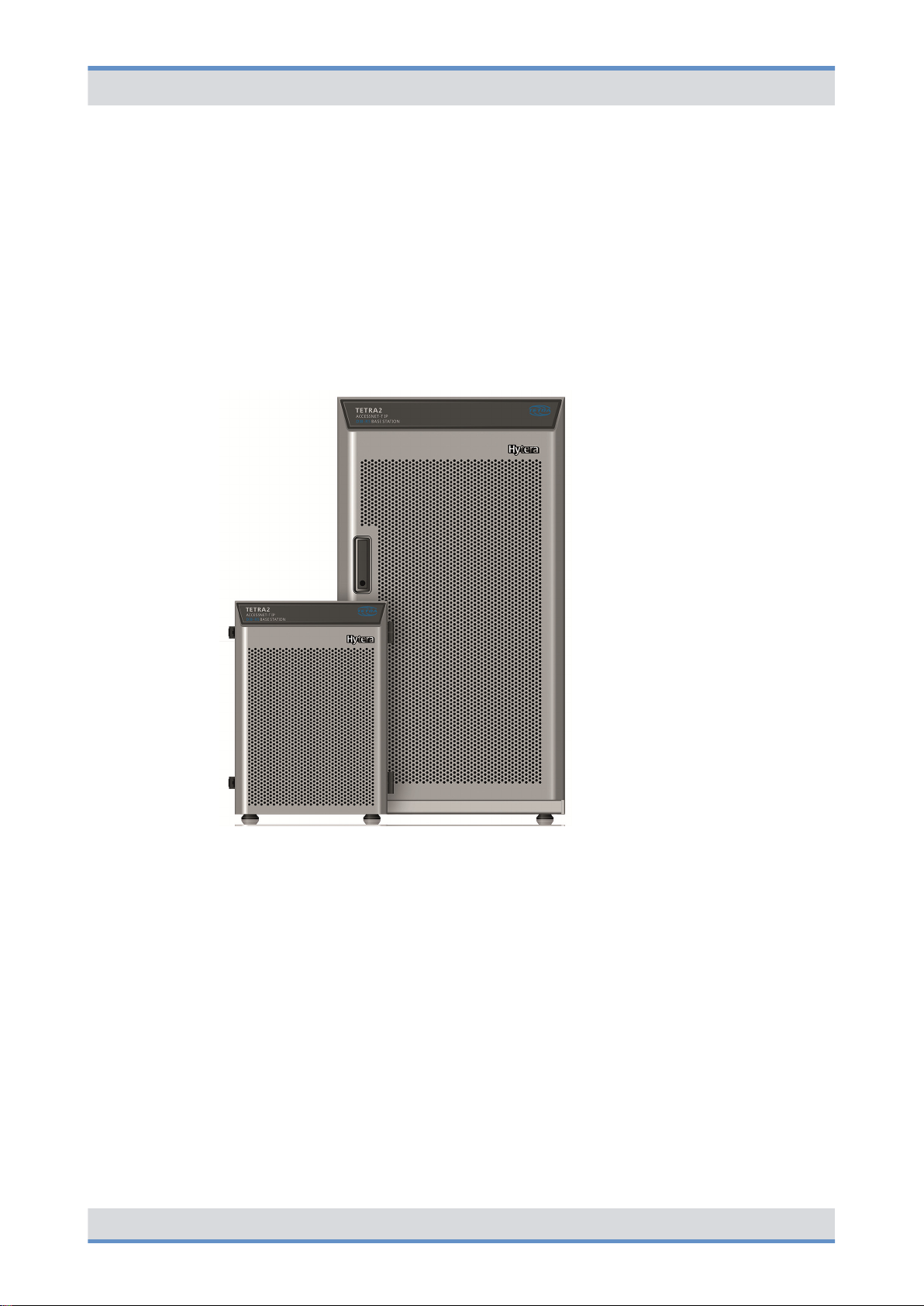
The DIB-R5 base station family is a constituent of the TETRA mobile radio system
ACCESSNET-T IP and ensures the powerful and reliable mobile radio coverage of a specific area. Pioneering TETRA Release 2 support, particularly the TEDS technology
(TETRA Enhanced Data Service), render the DIB-R5 extremely attractive for all scenarios
in which a high degree of availability as well as high-speed data are absolutely necessary. The TEDS data transmission allows transferring up to 150 kbit/s (gross bit rate)
securely and reliably via the air interface.
Figure 4: DIB-R5 family
The different variants of the base station family DIB-R5 meet customer and network
requirements in a perfect way. The following variants of the DIB-R5 are available:
n DIB-R5 advanced
The DIB-R5 advanced offers up to eight TETRA carriers with cavity combiner and
consists of one or two equipment racks depending on the number of carriers.
n DIB-R5 compact
The DIB-R5 compact offers up to four TETRA carriers with hybrid combiner and consists of one or two compact racks depending on the number of carriers.
DIB-R5 compact is suitable for space-saving installation in existing 19" equipment
racks.
n DIB-R5 flexibleTx
The DIB-R5 flexibleTx provides up to four TETRA carriers in a compact rack and is
operated project-specific with external antenna coupling systems. DIB-R5 flexibleTx is
suitable for space-saving installation in existing 19" equipment racks.
23Operation Manual 90DIBR5flexibleTxOM02 - 1.2

Product description
DIB-R5 flexibleTx
The hardware design of DIB-R5 features a modular layout. This allows hardware components to be replaced or added during ongoing operation.
Properties of the DIB-R5 flexibleTx
In each compact rack DIB-R5 flexibleTx offers space for four TETRA Channel Units
(CHU), which are each providing one TETRA carrier. Thus offers DIB-R5 flexibleTx a
maximum of 16 radio channels to the radio subscribers that can be used simultaneously.
To increase the availability, DIB-R5 flexibleTx can be equipped with different redundancy
options to avoid "Single Points of Failure". On the hardware side, the transceivers, control
unit and power supply can be designed redundantly. Furthermore, additional softwarebased redundancy options are available that further increase the reliability of features.
DIB-R5 flexibleTx is used project-specific with external antenna coupling systems. In
addition, DIB-R5 flexibleTx supports optimal reception of triple diversity with highest sensitivity. This optimizes the radio characteristic of the base stations and reduces the
number of base stations that are required for covering a certain area.
DIB-R5 flexibleTx can be configured depending on customer requests and network
requirements and expanded, e.g. through additional carriers. This allows the mobile radio
network to be adapted accordingly to meet new requirements and protect the current
investment.
Due to the compact dimensions and the low weight, the DIB-R5 flexibleTx can be optimally integrated into existing communication systems, e.g. into standard 19" equipment
racks. The compact design also eases transport, which can be undertaken using the integrated carrying handles if necessary.
For time synchronization, the DIB-R5 flexibleTx can be operated with satellite-based synchronization, e.g. GPS, Galileo and Glonass (Global Navigation Satellite System, GNSS).
As an alternative, the synchronization via the IP transport network can be carried out with
the help of the Precision Time Protocol (PTP). For this purpose, the base stations DIB-R5
are supplied with the time synchronization from a central point.
The continuous operation is also supported without satellite-based synchronization
sources. This allows a reliable operation even in underground areas or within buildings
without the need of using an antenna for the reception of a satellite signal.
The following figure shows the front view of the DIB-R5 flexibleTx with four TETRA
Channel Units (CHU) and VAC power supply. The following table describes the compo-
nents in greater detail.
24 Operation Manual 90DIBR5flexibleTxOM02 - 1.2

DIB-R5 flexibleTx
Product description
Figure 5: DIB-R5 flexibleTx (front view)
Legend: DIB-R5 flexibleTx (front view)
No. Component Number Described in
1 ADU 1 to 3
2 Cable routing for Tx cable 1 ---
3 Cable routing for Rx and GNSS cable
(Global Navigation Satellite System,
GNSS)
1 ---
Ä
Chapter 3.2.4.1 “Active Divider
Unit (ADU)” on page 45
25Operation Manual 90DIBR5flexibleTxOM02 - 1.2

Product description
No. Component Number Described in
DIB-R5 flexibleTx
4 TETRA Channel Unit (CHU) 1 to 4
5 Base Station Controller Unit (BSCU) 1 to 2
6 Fan unit 1
7 Air entry for fan unit 1 ---
8
9 Dummy plate 1 ---
10 Support feet 4 ---
n VAC power supply:
Power Supply Unit (PSU) including
Power Supply Module (PSM)
n VDC power supply:
Dummy plate
The following figure shows the top view of the DIB-R5 flexibleTx with VAC power supply.
The following table describes the components in greater detail.
n 1 to 2
n 0
Ä
Unit (CHU)” on page 46
Ä
troller Unit (BSCU)” on page 49
Ä
on page 53
Ä
Unit (PSU) including Power Supply
Module (PSM)” on page 40
Chapter 3.2.5 “TETRA Channel
Chapter 3.2.6 “Base Station Con-
Chapter 3.2.7 “Fan unit”
Chapter 3.2.2.2 “Power Supply
26 Operation Manual 90DIBR5flexibleTxOM02 - 1.2

DIB-R5 flexibleTx
Product description
Figure 6: DIB-R5 flexibleTx (top view)
Legend: DIB-R5 flexibleTx (top view)
No. Component Number Described in
1
n VAC power supply:
AC Power Distribution Module
(APDM)
n VDC power supply:
DC Power Distribution Module
(DPDM)
2 Connection panel 1
1 to 2
nÄ Chapter 3.2.2 “V
power supply”
on page 38
nÄ Chapter 3.2.3 “V
power supply”
on page 42
Ä
Chapter 3.2.1.2 “Connec-
tion panel” on page 36
3 GNSS splitter 1
Ä
Chapter 3.2.1.3 “GNSS
splitter” on page 38
AC
DC
27Operation Manual 90DIBR5flexibleTxOM02 - 1.2
 Loading...