

Page 1

ACCESSNET®-T IP
DIB-R5 advanced
Digital Integrated Base Station
Operation Manual
90DIBR5advancedOM02 - 1.0© 2014 Hytera Mobilfunk GmbH
Page 2

DIB-R5 advanced
Hytera Mobilfunk GmbH
Fritz-Hahne-Straße 7
D-31848 Bad Münder
Germany
Telephone: +49 (0)5042 / 998-0
Fax: +49 (0)5042 / 998-105
E-mail: info@hytera.de
Internet: www.hytera-mobilfunk.com
Read the instructions thoroughly prior to performing any tasks!
Keep these instructions for reference.
Subject to change without notice. Data without tolerance limits is not binding.
ACCESSNET and all derivatives are registered trademarks of Hytera Mobilfunk GmbH. HYT and Hytera are
registered trademarks of Hytera Communications Corporation Limited.
2 Operation Manual 90DIBR5advancedOM02 - 1.0
Page 3

DIB-R5 advanced
1 Notes on the document.................................................................................................. 7
1.1 Objectives of the document........................................................................................... 7
1.2 Intended audience of the document............................................................................. 7
1.3 Qualification of the personnel....................................................................................... 7
1.4 Reading and navigation aids in the document ........................................................... 8
1.5 Figures and special notations used.............................................................................. 8
1.5.1 Figures used..................................................................................................................... 8
1.5.2 Special notations.............................................................................................................. 8
1.5.2.1 Operating procedures....................................................................................................... 9
1.5.2.2 Safety instructions used.................................................................................................... 9
1.5.2.3 General instructions used............................................................................................... 10
1.5.2.4 Text formatting used....................................................................................................... 10
1.6 Further applicable documents.................................................................................... 11
1.7 Support information..................................................................................................... 12
2 Safety regulations......................................................................................................... 13
2.1 Intended use.................................................................................................................. 13
2.2 Safety measures........................................................................................................... 13
2.2.1 Authorized personnel...................................................................................................... 14
2.2.2 Electromagnetic compatibility......................................................................................... 14
2.2.3 Notes on the electrical system........................................................................................ 15
2.3 Safety and responsibility............................................................................................. 15
2.4 Safety markings............................................................................................................ 15
2.4.1 Safety markings on the product...................................................................................... 15
2.4.2 Safety markings on transport boxes............................................................................... 15
2.4.2.1 Safety marking "Fragile"................................................................................................. 16
2.4.2.2 Safety marking "Transport Upright"................................................................................ 16
2.4.2.3 Safety marking "Keep dry".............................................................................................. 17
3 Product description...................................................................................................... 19
3.1 Characteristics of the DIB-R5...................................................................................... 26
3.2 Components.................................................................................................................. 27
3.2.1 Connection and control panel......................................................................................... 28
3.2.1.1 On/off switch................................................................................................................... 29
3.2.1.2 Connection panel............................................................................................................ 29
3.2.1.3 GNSS splitter.................................................................................................................. 31
Table of contents
Table of contents
3Operation Manual 90DIBR5advancedOM02 - 1.0
Page 4

Table of contents
3.2.2 VAC voltage supply.......................................................................................................... 31
3.2.2.1 AC Power Distribution Module (APDM).......................................................................... 31
3.2.2.2 Power Supply Unit (PSU) including Power Supply Module (PSM)................................. 33
3.2.3 VDC voltage supply.......................................................................................................... 35
3.2.4 Divider Unit (DIU)............................................................................................................ 37
3.2.4.1 RX FILTER..................................................................................................................... 38
3.2.4.2 Passive Divider Unit (PDU) ‒ only in case of a CHU expansion.................................... 39
3.2.5 Transmitting filter............................................................................................................ 40
3.2.5.1 DUPLEXER.................................................................................................................... 40
3.2.5.2 TX FILTER...................................................................................................................... 41
3.2.6 TETRA Channel Unit (CHU)........................................................................................... 42
3.2.7 Base Station Controller Unit (BSCU).............................................................................. 44
3.2.8 Interconnection Relay Unit (IRU) ‒ only in the case of a CHU expansion...................... 48
3.2.9 Fan unit........................................................................................................................... 50
3.2.10 Cavity combiner.............................................................................................................. 51
DIB-R5 advanced
3.2.11 Backplane....................................................................................................................... 52
3.3 Interfaces....................................................................................................................... 54
3.4 Wiring diagrams............................................................................................................ 55
3.4.1 Internal wiring................................................................................................................. 56
3.4.1.1 Internal wiring with four CHUs and DUPLEXER............................................................. 56
3.4.1.2 Internal wiring with four CHUs and TX FILTER.............................................................. 57
3.4.2 Wiring of two equipment racks ‒ only in the case of a CHU expansion......................... 58
3.4.3 Antenna configurations................................................................................................... 59
3.4.3.1 Antenna configuration with four CHUs and DUPLEXER................................................ 59
3.4.3.2 Antenna configuration with four CHUs and TX FILTER.................................................. 59
3.5 Redundancy options.................................................................................................... 60
3.5.1 Redundant main control channel (MCCH)...................................................................... 61
3.5.2 Transceiver redundancy................................................................................................. 61
3.5.3 Controller redundancy.................................................................................................... 61
3.5.4 Fallback operation.......................................................................................................... 61
3.5.5 Stand-alone operation.................................................................................................... 62
3.5.6 Redundant VAC voltage supply....................................................................................... 62
3.5.6.1 Redundant rectifier modules (Power Supply Module, PSM)........................................... 63
3.5.6.2 Redundant voltage supply feeds.................................................................................... 63
3.5.7 Redundant connection to the transport network............................................................. 63
3.5.8 Redundant synchronization (GNSS, PTP)...................................................................... 63
3.6 Scope of delivery.......................................................................................................... 64
4 Operation Manual 90DIBR5advancedOM02 - 1.0
Page 5

DIB-R5 advanced
4 Operation....................................................................................................................... 65
4.1 Safety measures and prerequisites............................................................................ 65
4.2 Switching on the DIB-R5 advanced............................................................................ 66
4.3 Function tests and operating surveillance................................................................. 67
4.3.1 Work equipment for function tests.................................................................................. 68
4.3.2 Connecting the service computer................................................................................... 69
4.3.3 Checking operating states.............................................................................................. 70
4.3.3.1 Checking operating states (via LEDs)............................................................................ 70
4.3.3.2 Checking operating states (audible check)..................................................................... 70
4.3.3.3 Checking operating states (via the NMC-511 FaultManager)......................................... 71
4.3.4 Checking the availability................................................................................................. 72
4.3.5 Checking standby carriers ‒ optional.............................................................................. 73
4.3.6 Function tests and operating surveillance GNSS........................................................... 74
4.3.6.1 Checking the installation site of the GNSS antenna....................................................... 74
4.3.6.2 GNSS operational monitoring (via NMC-511 FaultManager)......................................... 75
5 Service interruption...................................................................................................... 77
5.1 Shutting down hardware components....................................................................... 77
5.2 Switching off the DIB-R5 advanced............................................................................ 78
6 Recommissioning......................................................................................................... 81
7 Maintenance.................................................................................................................. 83
7.1 Maintenance tasks........................................................................................................ 83
7.2 Periodical visual inspections...................................................................................... 83
8 Troubleshooting........................................................................................................... 85
Table of contents
5Operation Manual 90DIBR5advancedOM02 - 1.0
Page 6

Table of contents
DIB-R5 advanced
6 Operation Manual 90DIBR5advancedOM02 - 1.0
Page 7

DIB-R5 advanced
1 Notes on the document
1.1 Objectives of the document
Notes on the document
Qualification of the personnel
This chapter provides information on using the document. In addition, it specifies requirements that are absolutely necessary when working with the product.
The present document from Hytera Mobilfunk GmbH describes the procedures that are
required for the activities on and with the product:
n Operation
n Service interruption
n Recommissioning
n Maintenance
In this context, it describes the relevant safety regulations as well as the components and
operation of the product that is used in the ACCESSNET-T IP mobile radio system.
1.2 Intended audience of the document
The present document reverts to all the persons, who:
n operate an ACCESSNET-T IP TETRA mobile radio system
n commission and decommission the product
n maintain the product
Each person commissioned with performing the tasks mentioned above with or on the
system must have read and understood the present document and the associated
accompanying documentation.
1.3 Qualification of the personnel
Only experts are permitted to perform the tasks described in the present document. The
experts must be authorized to perform these tasks.
Experts are persons, who:
n are trained and experienced in the corresponding field.
n are familiar with the applicable standards, regulations and provisions associated with
the corresponding task.
7Operation Manual 90DIBR5advancedOM02 - 1.0
Page 8

Notes on the document
Figures and special notations used > Special notations
1.4 Reading and navigation aids in the document
As reading and navigation aids, overview tables have been provided at the beginning of
the respective chapters in the present document. These are to provide the reader with an
overview of the tasks to be performed. In addition, they indicate the order in which the
tasks are to be performed. When you have completed a work step, always navigate to the
next work step via the overview table to ensure that the tasks are performed in the correct
order. The overview tables are useful for readers of the printed document (indication of
the corresponding chapters) as well as for readers of a PDF document at the PC (via
active cross-references to the corresponding chapters).
1.5 Figures and special notations used
Figures and symbols are used in the present document. They are used to illustrate the
product and to emphasize particular pieces of information.
DIB-R5 advanced
1.5.1
1.5.2
Figures used
The figures used in this document show the product, if necessary in a simplified form for
clarity (e.g. technical drawings). They refer to different product designs. If not described
otherwise, the respective figure relates to the standard product design.
Special notations
The special forms of notation described below are intended to make it easier to understand the information. They emphasize specific pieces of information, help you to recognize this information fast and take corresponding measures.
8 Operation Manual 90DIBR5advancedOM02 - 1.0
Page 9

DIB-R5 advanced
1.5.2.1 Operating procedures
Notes on the document
Figures and special notations used > Special notations
The present document describes the tasks that have to be performed in the form of operating procedures. Standard operating procedures guide you step by step through a
sequence of actions until you have reached the desired goal.
Example of a sequence of actions:
Goal of the actions
Preparation:
n List of the prerequisite(s) for an action
n ...
1. Description of the first of several work steps.
A possible result of the work step just performed.
ð
2. Description of the second work step.
➔ Confirmation: Results of the entire sequence of actions.
1.5.2.2 Safety instructions used
Safety instructions in this document point to a hazard that may put persons or the
product/system at risk.
Within a safety instruction, the following items are brought to your attention:
n Type of hazard
n Source of hazard
n Measures to be taken to avert the specified hazard
Shown below are four security advice symbols which indicate the severity of the danger
by means of different keywords (danger, warning, caution, attention). The symbols shown
may vary depending on the nature and source of the danger.
This symbol identifies security instructions
You are warned of an imminent danger for the life or health of persons.
➔ The arrow identifies a precautionary measure designed to avert this danger.
This symbol identifies security instructions
You are warned of a potential hazard for the life or health of persons.
➔ The arrow identifies a precautionary measure designed to avert this danger.
9Operation Manual 90DIBR5advancedOM02 - 1.0
Page 10

Notes on the document
Figures and special notations used > Special notations
This symbol identifies security instructions
You are warned of a potentially hazardous situation for the life or health of persons.
➔ The arrow identifies a precautionary measure designed to avert this danger.
This symbol identifies security instructions.
You are warned of a hazard for the product.
➔ The arrow identifies a precautionary measure designed to avert this danger.
1.5.2.3 General instructions used
DIB-R5 advanced
General instructions provide supplementary and useful information.
Important Information
This symbol identifies information that may assist in handling and using the product.
This includes references to further information.
1.5.2.4 Text formatting used
The following table provides an overview of the text formats used and describes the significance of these formats.
Text formatting used
Text formatting Description Example
Example Identifies components of the user
Buttons, dialogs etc.
interface of software components
such as network management clients
(NMC).
Example Identifies required inputs. Passwords, IP
addresses etc.
Example
10 Operation Manual 90DIBR5advancedOM02 - 1.0
Identifies outputs. Panel outputs etc.
Page 11

DIB-R5 advanced
1.6 Further applicable documents
Notes on the document
Further applicable documents
Apart from the present documentation, the scope of delivery of the product includes additional documents. In addition to the contents of the present documentation, all the other
documents associated with the product must always be taken into consideration. They
are mandatory for the use of the product. If required, revert to Hytera Mobilfunk GmbH to
request the other applicable documents.
These are:
n DIB-R5 advanced Technical Data,
describe the technical properties of the product.
n DIB-R5 advancedSite Requirements,
describe the requirements for the site where the product is used.
n DIB-R5 advanced Installation Manual
describes the proper setup and electric connection of the product at the site.
n DIB-R5 advanced Configuration Manual,
describes the configuration of the product.
n DIB-R5 advancedService and Maintenance manual,
describes the maintenance and care of the product and the replacement of the components installed in the product
n Requirement Manual IP/VoIP
describes the requirements for securing the IP communication within
ACCESSNET-T IP mobile radio networks as well as outside, e.g. via VoIP telephone
systems (Voice-over-IP, VoIP).
n ACCESSNET-T IP Service Computer Configuration Manual
describes the configuration of the service computer that is used for the installation
and commissioning of network constituents of the ACCESSNET-T IP as well as for
service and maintenance purposes.
n User manuals of network management clients
provides information required for proper operation of the product and support troubleshooting.
The user manuals for the following products must be observed:
– NMC-511 FaultManager
– NMC-515 ConfigurationManager
n Open Source Acknowledgement
contains information on the respective Open Source software the product comprises,
including the information on the license(s) used and the related license agreements.
n ACCESSNET-T IP Versions
contains information about all versions that are valid for the present PV, such as component versions of software components or document versions.
n project-specific documents such as the "Base Design" document, where applicable,
describes the implemented network and the associated properties and requirements.
Further applicable documents
Please also heed the documentation of the third-party devices connected to the product
to prevent negative effects or problems with product.
11Operation Manual 90DIBR5advancedOM02 - 1.0
Page 12

Notes on the document
Support information
1.7 Support information
If you have any questions or proposals with regard to the products of Hytera Mobilfunk
GmbH, please revert to your local service partner or directly to Hytera Mobilfunk GmbH.
For a fast and cost-effective solution of any technical problems that come up during the
operation of your ACCESSNET-T IP mobile radio system, Hytera Mobilfunk GmbH offers
support contracts upon request. For information on this topic, please also revert to your
local service partner or directly to Hytera Mobilfunk GmbH.
Product training courses assist you in making use of the full scope of features and capabilities of your ACCESSNET-T IP mobile radio system. For information on the training
program of Hytera Mobilfunk GmbH, please revert to our responsible service partner, to
your local Hytera branch office or directly to Hytera Mobilfunk GmbH.
Hytera Mobilfunk GmbH
Fritz-Hahne-Straße 7
D-31848 Bad Münder
Germany
Telephone: +49 (0)5042 / 998-0
Fax: +49 (0)5042 / 998-105
E-mail: info@hytera.de
Internet: www.hytera-mobilfunk.com
DIB-R5 advanced
12 Operation Manual 90DIBR5advancedOM02 - 1.0
Page 13

DIB-R5 advanced
2 Safety regulations
2.1 Intended use
Safety regulations
Safety measures
This chapter describes the safety regulations relevant for using the product
DIB-R5 advanced.
The product is exclusively designed for being used as a professional TETRA base station. In this application it is used for the wireless communication between subscribers
equipped with the corresponding mobile stations as well as for switching calls and transferring data between subscribers within a TETRA (Terrestrial Trunked Radio) network.
Intended use also includes that:
n all the security instructions set forth in the product documents are always heeded,
n all the maintenance tasks described are performed in the interval specified,
n the general, national and in-house safety regulations are heeded.
Any other use is impermissible.
The product is not used as intended, for example, if:
n the requirements described in the product documents haven't been met and instruc-
tions are disregarded,
n the product is modified structurally or technically without the approval of Hytera Mobil-
funk GmbH,
n replacement parts are used that differ from the components installed by default.
The operator of the product is responsible for damage to the product or damage caused
by the product if the product was used beyond the intended application range and/or was
not used as intended.
2.2 Safety measures
All the regulations specified in the following must be adhered to without fail:
n If extension cables or multiple socket outlets are used, make sure that they are
inspected for proper condition periodically.
n After any security-related parts have been replaced (e.g. power switch or circuit
breakers) a security check must be performed (visual inspection, protective grounding
conductor load, leakage resistance, leakage current measurement, function test).
n Observe other task-related security measures and requirements in the standard oper-
ating procedures.
13Operation Manual 90DIBR5advancedOM02 - 1.0
Page 14

Safety regulations
Safety measures > Electromagnetic compatibility
Heed the security labeling!
In addition to the safety notices described within the product documentation, all safety
labels attached in and on the product must be observed. They point out potential hazardous areas and must neither be removed nor changed.
2.2.1 Authorized personnel
The product may only transported, set up/installed, connected, commissioned, operated
and maintained by experts who know and follow the respective valid safety and installation regulations.
The experts must be authorized to perform the required tasks by the person responsible
for the security in the enterprise of the network operator.
Experts are persons who:
DIB-R5 advanced
2.2.2
n are trained and experienced in the corresponding field,
n are familiar with the relevant standards, regulations, provisions and security codes,
n have been instructed in the mode of operation and the operating conditions of the
equipment components,
n can identify and avert dangers.
Depending on the tasks to be performed, the following user groups are distinguished:
n operators who
– operate the product,
– monitor, interrupt, terminate and restore operation of the product.
n Service personnel: persons who perform the following in addition to the tasks of the
operator:
– set up the product,
– prepare and restore the operational state,
– adjust and/or parameterize the product,
– maintain, care for, and repair the product.
Electromagnetic compatibility
For function-related reasons, increased electromagnetic radiation may occur with specific
products, e.g. HF radio systems. Taking into consideration that unborn life is increasingly
worthy of being protected, pregnant women should be protected through appropriate
measures. People with personal medical devices such as cardiac pacemakers and
hearing aids can also be endangered by electromagnetic radiation. The operator is
obliged to assess workplaces with a considerable risk of exposure to radiation and to
avert any hazards.
14 Operation Manual 90DIBR5advancedOM02 - 1.0
Page 15

DIB-R5 advanced
2.2.3 Notes on the electrical system
2.3 Safety and responsibility
Safety regulations
Safety markings > Safety markings on transport boxes
The product may be operated only in the operational states specified by the manufacturer
without impairment of the ventilation.
Make sure that all the security measures on the equipment, on the connecting cables and
on the load have been taken. Electrical connections may be made/disconnected only
when neither voltage nor current is applied to the equipment. Voltage may still be present
on the outputs of the equipment after the device has been switched off.
Only perform those tasks described in the documents included in the scope of delivery of
the product.
The following chapter lists all relevant security notices for the safe handling of the
product. The listed security notices must be followed for all operations on the product.
Observing the product documentation
The product documentation is part of the product and an important component in the
security concept. Its non-observance can result in serious injuries or even death.
➔ Read the product documentation and always follow all described procedures and
warning notices.
➔ Always keep the product documentation next to the product.
➔ Pass on the product documentation to all subsequent users.
2.4 Safety markings
The following chapters describe security markings on the product and its packaging.
2.4.1
2.4.2
Safety markings on the product
The product is equipped with security markings. They serve as an indication to possible
hazards and may not be deleted or modified (if necessary, marking in accordance with
DIN 4844 BGV A8 [VBG 125]).
Safety markings on transport boxes
To protect against improper handling of the product during a transport, the transport
boxes and the product itself are fitted with corresponding security markings to call attention to proper handling.
15Operation Manual 90DIBR5advancedOM02 - 1.0
Page 16

Safety regulations
Safety markings > Safety markings on transport boxes
Transport inspection using impact indicators
To check whether a product was properly transported, the transport boxes are fitted with
impact indicators. The impact indicator shows heavy impacts or vibrations that were
caused by an improper transport.
The following chapters describe the used security markings and indicate that the corresponding instructions must be followed.
2.4.2.1 Safety marking "Fragile"
The security marking "Fragile" points to the necessary protection of the product against
shock. Transport boxes with this marking must absolutely be protected against shock.
DIB-R5 advanced
Figure 1: Safety marking "Fragile"
2.4.2.2 Safety marking "Transport Upright"
The security marking "Transport Upright" points to the cover of the transport box. Transport boxes with this marking must always be transported with the cover at the top.
Figure 2: Safety marking "Transport Upright"
16 Operation Manual 90DIBR5advancedOM02 - 1.0
Page 17

DIB-R5 advanced
2.4.2.3 Safety marking "Keep dry"
Safety regulations
Safety markings > Safety markings on transport boxes
The security marking "Keep dry" points to the necessary protection of the product against
wetness (e.g. rain, high humidity during the transport in closed vehicles/containers and/or
formation of condensate when covered with a tarpaulin). Transport boxes with this
marking must absolutely be protected against any wet influences.
Figure 3: Safety marking "Keep dry"
17Operation Manual 90DIBR5advancedOM02 - 1.0
Page 18

Safety regulations
Safety markings > Safety markings on transport boxes
DIB-R5 advanced
18 Operation Manual 90DIBR5advancedOM02 - 1.0
Page 19

DIB-R5 advanced
3 Product description
Product description
The DIB-R5 base station family is a constituent of the TETRA mobile radio system
ACCESSNET-T IP and ensures the powerful and reliable mobile radio coverage of a specific area. Trendsetting TETRA Release 2 and TETRA Enhanced Data Service (TEDS)
support make the DIB-R5 extremely attractive for all scenarios in which a high degree of
availability as well as high speed data are a must. The TEDS data transmission allows
transferring up to 150 kbit/s (gross bit rate) securely and reliably via the air interface.
Figure 4: DIB-R5 family
The different variants of the DIB-R5 base station family meet the customer and network
requirements in a perfect way. The following variants of the DIB-R5 are available:
n DIB-R5 advanced
The DIB-R5 advanced offers up to eight TETRA carriers with cavity combiner.
DIB-R5 advanced consists of one or two equipment racks depending on the number
of carriers.
n DIB-R5 compact
The DIB-R5 compact offers up to two TETRA carriers with hybrid combiner.
DIB-R5 compact is suitable for space-saving installation in existing 19" equipment
racks.
The hardware design of DIB-R5 features a modular layout. This allows hardware components to be replaced or added during ongoing operation.
19Operation Manual 90DIBR5advancedOM02 - 1.0
Page 20

Product description
DIB-R5 advanced
In each equipment rack DIB-R5 advanced offers space for four TETRA Channel Units
(CHU), which are each providing one TETRA carrier. By using a second equipment rack,
up to eight carriers are supported. Thus offers DIB-R5 advanced a maximum of 32 radio
channels to the radio subscribers that can be used simultaneously. To increase the availability, DIB-R5 advanced can be equipped with different redundancy options to avoid
"Single Points of Failure". On the hardware side, the transceivers, control unit and voltage
supply can be designed redundantly. Furthermore, additional software-based redundancy
options are available that further increase the reliability of features.
DIB-R5 advanced supports different system configurations of the antenna coupling
system, including motor-tuned cavity combiner. This enables individual and fast remote
frequency change. In addition, DIB-R5 advanced supports for optimal reception triple
diversity. This optimizes the radio characteristic of the base stations and reduces the
number of base stations that are required for covering a certain area.
DIB-R5 advanced can be configured depending on customer requests and network
requirements and expanded e.g. through additional carriers. This allows the mobile radio
network to be adapted accordingly to meet new requirements and protect the current
investment.
For time synchronization, the DIB-R5 advanced compact can be operated optionally with
satellite-based synchronization, e.g. GPS, Galileo and Glonass (Global Navigation Satellite System, GNSS).The continuous operation is also supported without satellite-based
synchronization sources. This allows a reliable operation even in underground areas or
within buildings without the need of using an antenna for the reception of a satellite
signal.
The following figure shows the front view of the DIB-R5 advanced with four TETRA
Channel Units (CHU) and DUPLEXER. The following table describes the components in
greater detail.
20 Operation Manual 90DIBR5advancedOM02 - 1.0
Page 21

DIB-R5 advanced
Product description
Figure 5: DIB-R5 advanced (front view)
21Operation Manual 90DIBR5advancedOM02 - 1.0
Page 22

Product description
Legend: DIB-R5 advanced (front view)
No. Component Number Described in
DIB-R5 advanced
1 RX FILTER 1 to 3
2 DUPLEXER 1
3 Cable routing for Rx and GNSS cable
(Global Navigation Satellite System,
GNSS)
4 TETRA Channel Unit (CHU) 1 to 4
5 Base Station Controller Unit (BSCU) 1 to 2
6 Cable routing for Tx cable 1 ---
7 Fan unit 1
8 Air entry for fan unit 1 ---
9 Power Supply Unit (PSU) including
Power Supply Module (PSM)
Dummy plate for VDC voltage supply
10 Cavity combiner 1
1 ---
1 to 4
Ä
on page 38
Ä
on page 40
Ä
(CHU)” on page 42
Ä
Unit (BSCU)” on page 44
Ä
Ä
(PSU) including Power Supply Module
(PSM)” on page 33
Ä
on page 51
Chapter 3.2.4.1 “RX FILTER”
Chapter 3.2.5.1 “DUPLEXER”
Chapter 3.2.6 “TETRA Channel Unit
Chapter 3.2.7 “Base Station Controller
Chapter 3.2.9 “Fan unit” on page 50
Chapter 3.2.2.2 “Power Supply Unit
Chapter 3.2.10 “Cavity combiner”
11 Levelling feet 4 ---
12 Transport rollers 4 ---
The following figure shows the top view of the DIB-R5 advanced. The following table
describes the components in greater detail.
22 Operation Manual 90DIBR5advancedOM02 - 1.0
Page 23

DIB-R5 advanced
Product description
Figure 6: DIB-R5 advanced (top view)
Legend: DIB-R5 advanced (top view)
No. Component Number Described in
1 Rear equipment rack door 1 ---
2 Lifting rings 4 ---
3 Cable fastening for voltage supply
1 ---
cable
4
n AC Power Distribution Module
(APDM)
n DC Power Distribution Module
(DPDM)
1 to 2
nÄ Chapter 3.2.2 “V
voltage supply”
on page 31
nÄ Chapter 3.2.3 “V
voltage supply”
on page 35
AC
DC
23Operation Manual 90DIBR5advancedOM02 - 1.0
Page 24

Product description
DIB-R5 advanced
No. Component Number Described in
5 Connection panel 1
6 GNSS splitter 1
7 TX/RXC 1 ---
8 RXC ‒ optional 1 ---
9 RXB 1 ---
10 RXA 1 ---
11 Front equipment rack door 1 ---
The following figure shows the rear view of the DIB-R5 advanced with opened equipment
rack door. The following table describes the components in greater detail.
Ä
Chapter 3.2.1.2 “Connec-
tion panel” on page 29
Ä
Chapter 3.2.1.3 “GNSS
splitter” on page 31
24 Operation Manual 90DIBR5advancedOM02 - 1.0
Page 25

DIB-R5 advanced
Product description
Figure 7: DIB-R5 advanced with opened equipment rack door (rear view)
25Operation Manual 90DIBR5advancedOM02 - 1.0
Page 26

Product description
Characteristics of the DIB-R5
Legend: DIB-R5 advanced with opened equipment rack door (rear view)
No. Component Number Described in
DIB-R5 advanced
1
n AC Power Distribution Module
(APDM)
n DC Power Distribution Module
(DPDM)
2 Backplane 1
3 Cable routing 2 ---
4 Fan unit 1
5 Rear side of air inlet for fan unit 1 ---
6 Cable routing 1 ---
7 Cavity combiner 1
3.1 Characteristics of the DIB-R5
1 to 2
nÄ Chapter 3.2.2 “V
voltage supply”
on page 31
nÄ Chapter 3.2.3 “V
voltage supply”
on page 35
Ä
Chapter 3.2.11 “Back-
plane” on page 52
Ä
Chapter 3.2.9 “Fan unit”
on page 50
Ä
Chapter 3.2.10 “Cavity
combiner” on page 51
AC
DC
The DIB-R5 offers a high degree of flexibility and allows demand-oriented characteristics,
e.g. with respect to voltage supply, frequencies and redundancy options. Depending on
the characteristic, different components can be installed.
The following table describes the characteristics of the DIB-R5.
Characteristics of the DIB-R5
Component Characteristic
Voltage supply
n VAC voltage supply
– Redundant rectifier modules (Power Supply Module,
PSM)
– Redundant voltage supply feeds
n VDC voltage supply
Antenna coupling
system
n DUPLEXER
for a common transmitting/receiving antenna (Tx/Rx
antenna)
n TX FILTER
for separate transmitting and receiving antennas (Tx and
Rx antennas)
26 Operation Manual 90DIBR5advancedOM02 - 1.0
Page 27

DIB-R5 advanced
3.2 Components
Product description
The following table lists the components of the DIB-R5 advanced.
Components of the DIB-R5 advanced
Component Described in
Ä
Connection and
control panel
Ä
VAC voltage supply
Ä
On/off switch
Ä
Connection panel
Ä
GNSS splitter
Ä
Chapter 3.2.1.1 “On/
off switch” on page 29
Ä
Chapter 3.2.1.2
“Connection panel”
on page 29
Ä
Chapter 3.2.1.3
“GNSS splitter”
on page 31
Ä
Chapter 3.2.2 “V
voltage supply”
on page 31
Components
AC
Ä
VDC voltage supply
Ä
Divider Unit (DIU)
Ä
Transmitting filter
Ä
TETRA Channel Unit (CHU)
Ä
Base Station Controller Unit (BSCU)
Ä
Interconnection Relay Unit (IRU) ‒ only in the case of a
CHU expansion
Ä
RX FILTER
Ä
Passive Divider Unit (PDU)
only in case of a CHU expansion
Ä
DUPLEXER
Ä
TX FILTER
Ä
Chapter 3.2.3 “V
voltage supply”
on page 35
Ä
Chapter 3.2.4.1 “RX
FILTER” on page 38
‒
Ä
Chapter 3.2.4.2
“Passive Divider Unit
(PDU) ‒ only in case of
a CHU expansion”
on page 39
Ä
Chapter 3.2.5.1
“DUPLEXER”
on page 40
Ä
Chapter 3.2.5.2 “TX
FILTER” on page 41
Ä
Chapter 3.2.6
“TETRA Channel Unit
(CHU)” on page 42
Ä
Chapter 3.2.7 “Base
Station Controller Unit
(BSCU)” on page 44
Ä
Chapter 3.2.8 “Interconnection Relay Unit
(IRU) ‒ only in the case
of a CHU expansion”
on page 48
DC
Ä
Fan unit
Ä
Chapter 3.2.9 “Fan
unit” on page 50
27Operation Manual 90DIBR5advancedOM02 - 1.0
Page 28

Product description
Components> Connection and control panel
Component Described in
Ä
Cavity combiner
Ä
Backplane
3.2.1 Connection and control panel
The DIB-R5 advanced features a connection and control panel at the top side to which
the antenna and voltage supply cable can be connected conveniently from the top. Furthermore, the connection and control panel provides access to all the elements that are
required for additional connections and operation.
The following figure shows the top view of the connection and control panel. The following table describes it in detail.
DIB-R5 advanced
Ä
Chapter 3.2.10
“Cavity combiner”
on page 51
Ä
Chapter 3.2.11
“Backplane”
on page 52
Figure 8: Connection and control panel (top view)
28 Operation Manual 90DIBR5advancedOM02 - 1.0
Page 29

DIB-R5 advanced
Product description
Components> Connection and control panel
Legend: Connection and control panel (top view)
No. Component Description
1 On/off switch
2
3 Connection panel
4 GNSS splitter
5 TX/RXC Antenna connection for transmitting/
6 RXC ‒ optional Antenna connection for receiving
7 RXB Antenna connection for receiving
8 RXA Antenna connection for receiving
n VAC voltage supply
AC Power Distribution Module
(APDM)
n VDC voltage supply
DC Power Distribution Module
(DPDM)
refer to Ä Chapter 3.2.1.1 “On/off switch”
on page 29
nÄ Chapter 3.2.2 “VAC voltage supply”
on page 31
n
Ä
Chapter 3.2.3 “VDC voltage supply”
on page 35
refer to Ä Chapter 3.2.1.2 “Connection
panel” on page 29
refer to Ä Chapter 3.2.1.3 “GNSS splitter”
on page 31
receiving antenna C
antenna C
antenna B
antenna A
3.2.1.1 On/off switch
The on/off switch is accessible via the Power Distribution Module (PDM) in the connection
and control panel. The PDM is the main component of the voltage supply and is used for
connecting the voltage supply and the voltage distribution to the hardware components of
the DIB-R5 advanced.
With the VAC voltage supply, the on/off switch is available via the AC Power Distribution
Module (APDM), refer to Ä Chapter 3.2.2 “VAC voltage supply” on page 31.
With the VDC voltage supply, the on/off switch is available via the DC Power Distribution
Module (APDM), refer to
3.2.1.2 Connection panel
The connection panel combines all the essential connections, centrally and easily accessible at the top side, e.g. for connection to the transport network. Isolated alarm contacts
provide digital alarm inputs and alarm outputs. The alarm inputs can be monitored via the
network management system (NMS). This allows, for example, to monitor the status of
the surge protection device (SPD) of the DIB-R5 advanced in the NMC-511 FaultManager. Alarms with the corresponding critical state can be signaled externally via the alarm
outputs, e.g. with a connected light or ringing.
Ä
Chapter 3.2.3 “VDC voltage supply” on page 35.
29Operation Manual 90DIBR5advancedOM02 - 1.0
Page 30

Product description
Components> Connection and control panel
The connection panel is implemented by the alarm/connection box.
The following figure shows the top view of the connection panel. The following table
describes it in detail.
DIB-R5 advanced
Figure 9: Connection panel (top view)
Legend: Connection panel (top view)
No. Component Description Connector
type
1 ALARM INPUT Alarm inputs/outputs for wiring
2 ALARM OUTPUT
3 SCN1 Connection to an IP transport net-
4 SCN2
5 MCB1 Connection for applications RJ45
6 MCB2
alarm contacts
work or for connecting a switching
controller node (SCN).
With controller redundancy
(optional), both connections must
be connected to design the
ethernet connections of the
BSCUs redundantly.
Plug
RJ45
30 Operation Manual 90DIBR5advancedOM02 - 1.0
Page 31

DIB-R5 advanced
Product description
Components> VAC voltage supply
No. Component Description Connector
type
7 SW1 Connection of the service com-
8 SW2 Connection of service computer
3.2.1.3 GNSS splitter
The GNSS splitter (Global Navigation Satellite System) is used for connecting the GNSS
antenna and the splitting and distribution of the received GNSS signal (e.g. GPS, Galileo
or Glonass) to two BSCUs. The GNSS splitter is always installed in the connection and
control panel, even if only one BSCU is used.
3.2.2
VAC voltage supply
The DIB-R5 advanced can be operated with an input voltage of 90 VAC to 250 VAC.
RJ45
puter (local)
RJ45
(local) ‒ optional for controller
redundancy
This connection is required only if
software downloads should be
performed specifically for the
redundant BSCU.
The VAC voltage supply consists of the following components:
nÄ AC Power Distribution Module (APDM)
nÄ Power Supply Unit (PSU) including Power Supply Module (PSM)
3.2.2.1 AC Power Distribution Module (APDM)
The AC Power Distribution Module (APDM) is used for connecting the voltage supply and
the voltage distribution to the backplane and the installed hardware components. The
APDM is used for the VAC voltage supply. The VAC input voltage is fed via the Power
Supply Unit (PSU), converted to the required operating voltage, and subsequently distributed to the backplane and the installed hardware components.
With redundant voltage supply feed, two APDMs are installed (optional). The redundancy
options of the voltage supply are described in Ä Chapter 3.5.6 “Redundant VAC voltage
supply” on page 62.
The following figure shows the top view of the APDM. The following table describes it in
detail.
31Operation Manual 90DIBR5advancedOM02 - 1.0
Page 32

Product description
Components> VAC voltage supply
DIB-R5 advanced
Figure 10: APDM (top view)
Legend: APDM (top view)
No. Component Description
1 Surge protection Surge Protection Device (SPD) of the
DIB-R5 advanced
2 On/off switch On/off switch of the DIB-R5 advanced
3 Terminals Terminals for VAC input voltage
The following figure shows the front view of the APDM. The following table describes it in
detail.
32 Operation Manual 90DIBR5advancedOM02 - 1.0
Page 33

DIB-R5 advanced
Product description
Components> VAC voltage supply
Figure 11: APDM (front view)
Legend: APDM (front view)
No. Component Description
1 SPD ALARM Connection for monitoring the Surge Protection Device (SPD)
2 L Input Phase conductor connection for VAC input
voltage
3 N Neutral conductor connection for VAC input
voltage
4 PE Earthing conductor connection for VAC input
voltage
5 L Output Phase conductor connection for VAC output
voltage
6 N Neutral conductor connection for VAC output
voltage
7 PE Earthing conductor connection for VAC output
voltage
3.2.2.2 Power Supply Unit (PSU) including Power Supply Module (PSM)
The Power Supply Unit (PSU) is a component of the voltage supply and is used for the
VAC voltage supply.
Depending on the voltage supply, the number of installed CHUs and, if applicable, a
redundantly implemented voltage supply, up to four Power Supply Modules (PSM) are
installed.
The Power Supply Module (PSM) is a rectifier module and is used with VAC voltage
supply. The PSM is used for converting AC voltage (VAC) into DC voltage (VDC).
33Operation Manual 90DIBR5advancedOM02 - 1.0
Page 34

Product description
Components> VAC voltage supply
The following table describes the recommended number of PSMs depending on the
voltage supply and the number of installed CHUs per equipment or compact rack.
Recommended number of PSMs
Voltage supply Number of CHUs Number of PSMs
90 VAC - 170 VAC (nominal) 1 to 2 2
170 VAC - 250 VAC (nominal) 1 to 2 1
The following figure shows the front view of the PSU. The following table describes it in
detail.
DIB-R5 advanced
3 to 4 4
3 to 4 2
Figure 12: PSU (front view)
Legend: PSU (front view)
No. Component Description
1 Mounting frame The mounting frame is used for accommodating the Power
Supply Modules (PSM)
2 Power Supply
Module (PSM)
The following figure shows the front view of a PSM. The following table describes it in
detail.
Figure 13: PSM (front view)
Number depending on the VAC voltage at the location and
the number of installed CHUs, refer to Ä Table “Recom-
mended number of PSMs” on page 34
34 Operation Manual 90DIBR5advancedOM02 - 1.0
Page 35

DIB-R5 advanced
Product description
Components> VDC voltage supply
Legend: PSM (front view)
No. Component Color Description
1 green Lights if the VAC input voltage is OK
Flashes if the VAC input voltage is outside the
permissible voltage range
2 green Lights if the VDC output voltage is OK
Flashes if the VDC output voltage is overloaded
3 yellow Lights if the temperature warning threshold is
exceeded
Flashes in case of service
4 red Lights in case of an error
3.2.3 VDC voltage supply
The DIB-R5 advanced can be operated with an input voltage of 48 VDC.
The DC Power Distribution Module (DPDM) is used for connecting the voltage supply and
the voltage distribution to the backplane and the installed hardware components. The
DPDM is used for the VDC voltage supply. The VDC input voltage is distributed directly to
the backplane and the installed hardware components.
The following figure shows the top view of the DPDM. The following table describes it in
detail.
35Operation Manual 90DIBR5advancedOM02 - 1.0
Page 36
Product description
Components> VDC voltage supply
DIB-R5 advanced
Figure 14: DPDM (top view)
Legend: DPDM (top view)
No. Component Description
1 Surge protection Surge Protection Device (SPD) of the
DIB-R5 advanced
2 On/off switch On/off switch of the DIB-R5 advanced
3 Terminals Terminals for VDC input voltage
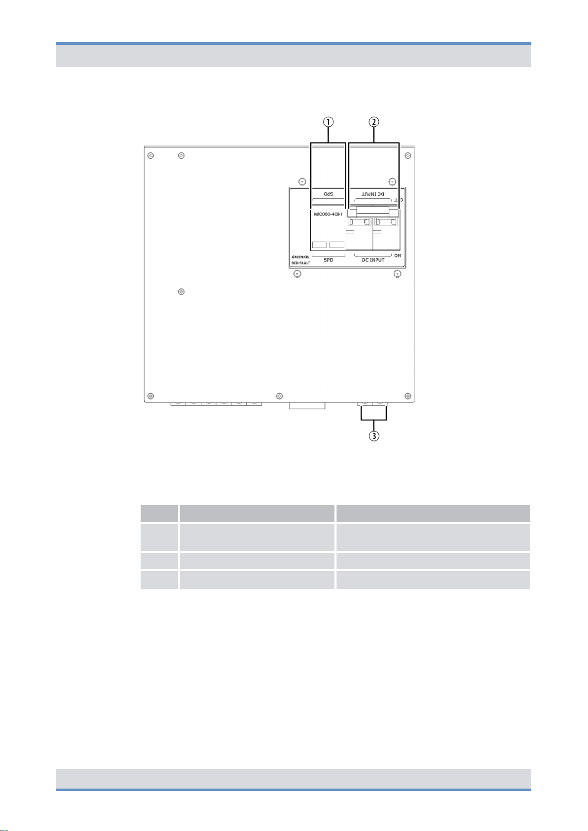
The following figure shows the front view of the DPDM. The following table describes it in
detail.
36 Operation Manual 90DIBR5advancedOM02 - 1.0
Page 37

DIB-R5 advanced
Product description
Components> Divider Unit (DIU)
Figure 15: DPDM (front view)
Legend: DPDM (front view)
No. Component Description
1 SPD ALARM Connection for monitoring the Surge Pro-
2 DC INPUT -48V Connection for the negative voltage line
3 RTN Connection for the positive voltage line
4 DC OUTPUT -48V Connection for the negative voltage line
5 RTN Connection for the positive voltage line
3.2.4 Divider Unit (DIU)
The Divider Unit (DIU) is a component of the antenna coupling system and is used for the
distribution of the signals received by all antennas onto the installed CHUs.
Different DIUs are used in the DIB-R5 advanced:
tection Device (SPD)
(input voltage)
(input voltage)
(output voltage)
(output voltage)
nÄ RX FILTER
Ä
Passive Divider Unit (PDU) ‒ only in case of a CHU expansion
n
The type used and the number of DIUs depends on the number of antennas and carriers.
37Operation Manual 90DIBR5advancedOM02 - 1.0
Page 38

Product description
Components> Divider Unit (DIU)
3.2.4.1 RX FILTER
The RX FILTER is used for receiving and repeating the received Rx signals. The Rx signals are distributed by the RX FILTER and passed on to the respective Channel Units
(CHU).
The number of RX FILTER depends on the number of receiving antennas (Rx antennas).
One RX FILTER is required for each Rx antenna.
The following figure shows the front view of the RX FILTER. The following table describes
it in detail.
DIB-R5 advanced
Figure 16: RX FILTER (front view)
Legend: RX FILTER (front view)
No. Component Description
1 RX1 Connector for the connection with CHU 1
2 RX2 Connector for the connection with CHU 2
3 RX3 Connector for the connection with CHU 3
38 Operation Manual 90DIBR5advancedOM02 - 1.0
Page 39

DIB-R5 advanced
3.2.4.2 Passive Divider Unit (PDU) ‒ only in case of a CHU expansion
Product description
Components> Divider Unit (DIU)
No. Component Description
4 RX4 Connector for the connection with CHU 4
5 Exp. BS Connector for the connection with a Passive Divider Unit
(PDU) in a second equipment rack ‒ only in case of more
than four CHUs
The Passive Divider Unit (PDU) is used for receiving and distributing the Rx signal
received by an RX FILTER. The Rx signals are passed on to the respective TETRA
Channel Units (CHU) by the PDU. The number of PDUs depends on the number of
receiving antennas (Rx antennas). One PDU is required for every Rx antenna.
PDUs are used only in base stations with more than four CHUs.
The following figure shows the front view of the PDU. The following table describes it in
detail.
Figure 17: PDU (front view)
39Operation Manual 90DIBR5advancedOM02 - 1.0
Page 40

Product description
Components> Transmitting filter
Legend: PDU (front view)
No. Component Description
1 RX1 Connector for the connection with CHU 1
2 RX2 Connector for the connection with CHU 2
3 RX3 Connector for the connection with CHU 3
4 RX4 Connector for the connection with CHU 4
5 RX-IN Connector for the connection with an RX
3.2.5 Transmitting filter
The DIB-R5 advanced offers a high degree of flexibility and enables demand-oriented
variants with respect to antenna configurations.
Depending on the antenna configuration, different transmitting filters are used that are
required for transmitting and receiving. Only one of the two transmitting filters is used in
the process.
One of the following transmitting filters is used in the DIB-R5 advanced:
DIB-R5 advanced
FILTER in a second equipment rack ‒ only
in case of more than four CHUs
nÄ DUPLEXER
Ä
TX FILTER
n
3.2.5.1 DUPLEXER
The DUPLEXER is used for separating the receiving and transmitting paths and is used if
a common transmitting/receiving antenna (Tx/Rx antenna) is used.
The following figure shows the front view of the DUPLEXER. The following table
describes it in detail.
Figure 18: DUPLEXER (front view)
40 Operation Manual 90DIBR5advancedOM02 - 1.0
Page 41
DIB-R5 advanced
3.2.5.2 TX FILTER
Product description
Components> Transmitting filter
Legend: DUPLEXER (front view)
No. Component Description
1 RX1 Connector for the connection with CHU 1
2 RX2 Connector for the connection with CHU 2
3 RX3 Connector for the connection with CHU 3
4 RX4 Connector for the connection with CHU 4
5 Exp. BS Connector for the connection with a PDU in a second equip-
ment rack ‒ only in case of more than four CHUs
6 TX-IN Tx connector
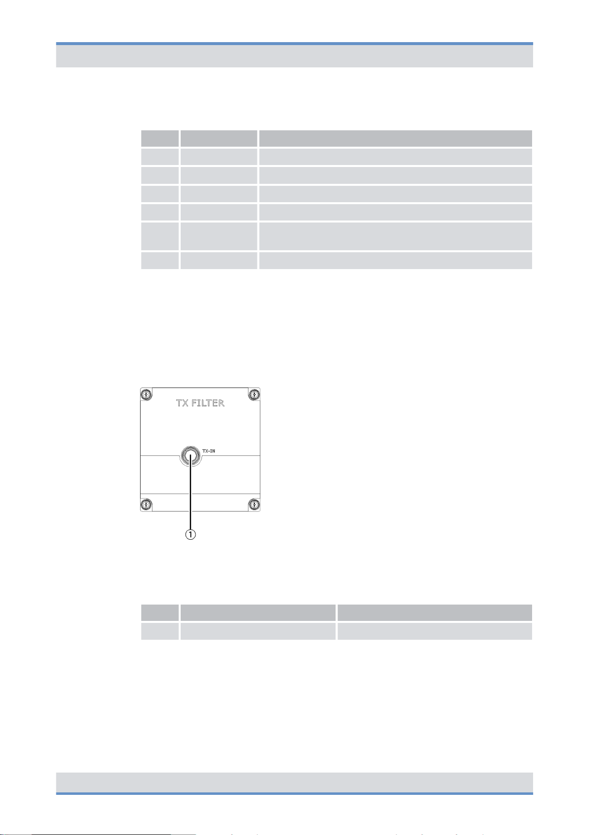
The TX FILTER is used for filtering the transmitting signal in the tuning range and is
applied if a separate transmitting antenna (Tx antenna) is used.
The following figure shows the front view of the TX FILTER. The following table describes
it in detail.
Figure 19: TX FILTER (front view)
Legend: TX FILTER (front view)
No. Component Description
1 TX-IN Tx connector
41Operation Manual 90DIBR5advancedOM02 - 1.0
Page 42
Product description
Components> TETRA Channel Unit (CHU)
3.2.6 TETRA Channel Unit (CHU)
The TETRA Channel Unit (CHU) is the transceiver module of the DIB-R5 and provides
four radio channels for the voice and data transmission in transmitting and receiving
direction (uplink and downlink) via one carrier signal. A transceiver consists of transmitter,
receiver and transceiver software for the TETRA protocol and generates a modulated RF
signal (carrier) with which signaling data and payload between the base station and the
mobile stations are exchanged. In addition to providing the carrier signal, the CHU provides monitoring and control functions, with which the fan speed can be controlled
dynamically, for example.
The CHU is a modular subrack for the DIB-R5 advanced and provides one carrier. The
DIB-R5 advanced can be expanded in a flexible way by additional CHUs, up to four
CHUs can be installed in one equipment rack. A CHU can be replaced during ongoing
operation in case of malfunctions to quickly re-establish radio coverage.
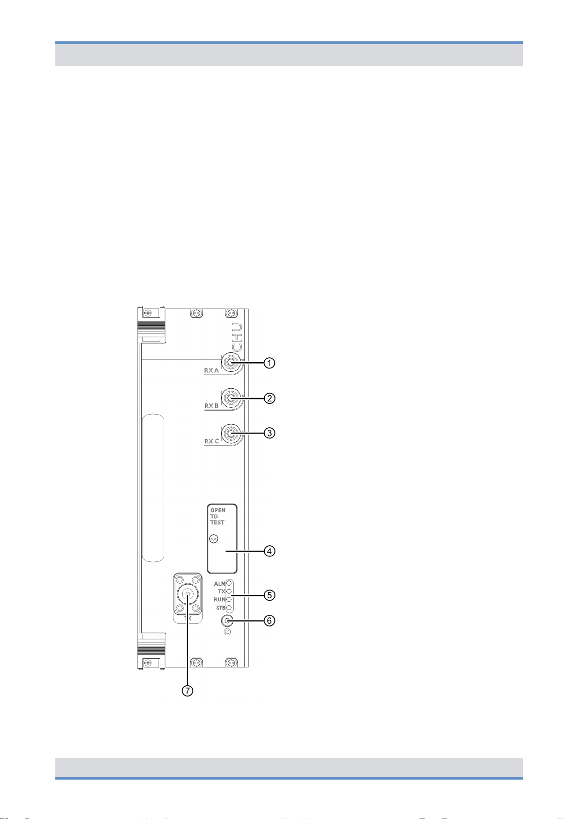
The following figure shows the front view of the CHU. The following table describes it in
detail.
DIB-R5 advanced
Figure 20: CHU (front view)
42 Operation Manual 90DIBR5advancedOM02 - 1.0
Page 43
DIB-R5 advanced
Product description
Components> TETRA Channel Unit (CHU)
Legend: CHU (front view)
No. Component Description
1 RX A Rx receiver input A
2 RX B Rx receiver input B
3 RX C Rx receiver input C
4 OPEN TO TEST Connectors for test and service purposes, refer to
Ä
Table “Legend: Connectors for test and service
purposes (OPEN TO TEST) of the CHU” on
page 43
5 Indicators (LEDs) Status display of the CHU, refer to
Ä
Table “Legend: Indicators (LEDs) of the CHU” on
page 44
6 Power button Power button for shutting down and restarting the
hardware component
7 TX Tx transmitter output
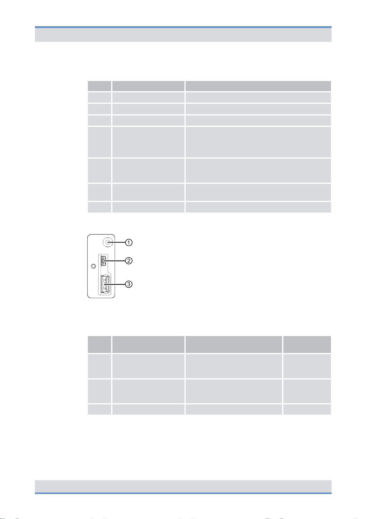
The following figure shows the connectors for test and service purposes (OPEN TO
TEST) of the CHU. The following table describes it in detail.
Figure 21: Connectors for test and service purposes (OPEN TO TEST) of the CHU
Legend: Connectors for test and service purposes (OPEN TO TEST) of the CHU
No. Component Description Connector
type
1 Multi-frame Connector for test and approval
measurements of the receiving
quality
2 Mini-USB USB port for the serial connection
to the console of the operating
system
SMB (male)
Mini-USB
3 USB-A USB port, e.g. for data exchange USB A
The following figure shows the indicators (LEDs) of the CHU. The following table
describes it in detail.
43Operation Manual 90DIBR5advancedOM02 - 1.0
Page 44

Product description
Components> Base Station Controller Unit (BSCU)
Figure 22: Indicators (LEDs) of the CHU
Legend: Indicators (LEDs) of the CHU
No. LED Color Description
1 ALM red Lights in case of an error
2 TX green Lights green if the transmitter of the CHU is switched on
3 RUN green Flashes if the CHU is in operation
4 STB yellow Lights if the CHU is in standby operation
DIB-R5 advanced
3.2.7 Base Station Controller Unit (BSCU)
The Base Station Controller Unit (BSCU) is the control unit of the base station and
secures the connections inside of the DIB-R5 advanced as well as to external network
constituents such as system controller nodes.
Furthermore, the BSCU receives and distributes satellite-based clock and timing signals
for the synchronization of the base stations, which are acquired via the integrated GNSS
component (Global Navigation Satellite System) with connected antenna. GNSS includes
all the common systems, such as GPS, Galileo and Glonass. As an option, time is
obtained via the Precision Time Protocol (PTP) from a so-called reference time source
(Grandmaster Clock).
In addition, the BSCU is the interface to the ACCESSNET-T IP, with which network constituents such as switching nodes, the network management system (NMS) or applications are connected.
The BSCU is a modular subrack for the DIB-R5 advanced. To increase availability, up to
two BSCUs can be installed. A BSCU can be replaced during ongoing operation in case
of malfunctions to quickly re-establish radio coverage, if a second BSCU is in operation.
The following figure shows the front view of the BSCU. The following table describes it in
detail.
44 Operation Manual 90DIBR5advancedOM02 - 1.0
Page 45

DIB-R5 advanced
Product description
Components> Base Station Controller Unit (BSCU)
Figure 23: BSCU (front view)
45Operation Manual 90DIBR5advancedOM02 - 1.0
Page 46
Product description
Components> Base Station Controller Unit (BSCU)
Legend: BSCU (front view)
No. Component Description
1 GNSS GNSS antenna connector (SMA)
2 Indicators (LEDs) Status display of the BSCU, refer to
3 OPEN TO TEST Connectors for test and service purposes, refer to
4 Power button Power button for shutting down and restarting the
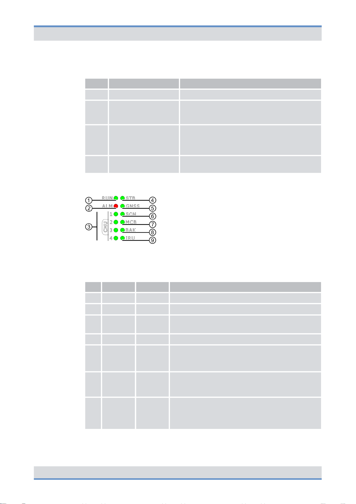
The following figure shows the indicators (LEDs) of the BSCU. The following table
describes it in detail.
DIB-R5 advanced
Ä
Table “Legend: Indicators (LEDs) of the
BSCU” on page 46
Ä
Table “Legend: Connectors for test and service
purposes (OPEN TO TEST) of the BSCU” on
page 47
hardware component
Figure 24: Indicators (LEDs) of the BSCU
Legend: Indicators (LEDs) of the BSCU
No. LED Color Description
1 RUN green Flashes if the BSCU is in operation
2 ALM red Lights in case of an error
3 CHU 1 to4green
4 STB green Lights if the BSCU is in standby operation
5 GNSS green
6 SCN green
7 MCB green
n Lights if connections to CHUs exist
n Flashes if data are being transferred
n Lights if a GNSS signal (e.g. GPS) is available
n Flashes if no GNSS signal is available
n Off if no connection exists to the GNSS module
n Lights if an ethernet connection exists for con-
necting a system controller node
n Flashes if data are being transferred
n Lights if a connection exists between the integrated
components ethernet switch and BSCU mainboard
(MCB)
n Flashes if data are being transferred
46 Operation Manual 90DIBR5advancedOM02 - 1.0
Page 47
DIB-R5 advanced
Product description
Components> Base Station Controller Unit (BSCU)
No. LED Color Description
8 BAK green
9 IRU green
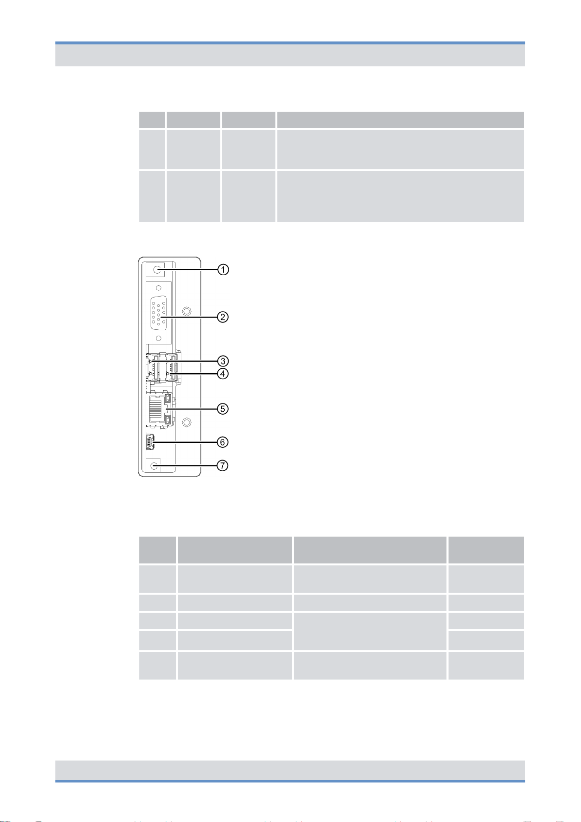
The following figure shows the connectors for test and service purposes (OPEN TO
TEST) of the BSCU. The following table describes it in detail.
n Lights if a connection exists between redundant
BSCUs
n Flashes if data are being transferred
n Lights if a connection exists to an Interconnection
Relay Unit (IRU) ‒ only in the case of two equipment racks
n Flashes if data are being transferred
Figure 25: Connectors for test and service purposes (OPEN TO TEST) of the BSCU
Legend: Connectors for test and service purposes (OPEN TO TEST) of the BSCU
No. Component Description Connector
type
1 10 MHz out Connector for measuring instru-
ments
2 VGA Monitor port VGA
3 USB1 USB port, e.g. for connecting a
4 USB2 USB A
5 LAN Ethernet port for the service com-
keyboard or a USB stick for software updates
puter
SMB (male)
USB A
RJ45
47Operation Manual 90DIBR5advancedOM02 - 1.0
Page 48

Product description
Components> Interconnection Relay Unit (IRU) ‒ only in the case of a CHU expansion
No. Component Description Connector
6 Mini-USB USB port for service purposes Mini-USB
DIB-R5 advanced
type
7 Reset button Reset button for restarting the
integrated BSCU Mainboard
(MCB) component
---
3.2.8 Interconnection Relay Unit (IRU) ‒ only in the case of a CHU expan-
sion
The Interconnection Relay Unit (IRU) is the receiving and distribution unit of the base station in a second equipment or compact rack and establishes the connection to a BSCU in
the first equipment or compact rack. All the control information as well as clock and time
signals are distributed by the IRU to the CHUs in the second equipment or compact rack
and kept synchronous.
The IRU is a modular subrack for the DIB-R5 advanced, up to two IRUs can be installed.
An IRU can be replaced during ongoing operation in case of malfunctions to quickly reestablish radio coverage.
The following figure shows the front view of the IRU. The following table describes it in
detail.
48 Operation Manual 90DIBR5advancedOM02 - 1.0
Page 49

DIB-R5 advanced
Product description
Components> Interconnection Relay Unit (IRU) ‒ only in the case of a CHU expansion
Figure 26: IRU (front view)
Legend: IRU (front view)
No. Component Description
1 Indicators (LEDs)
The following figure shows the indicators (LEDs) of the IRU. The following table describes
it in detail.
Status display of the IRU, refer to Ä Table “Legend:
Indicators (LEDs) of the IRU” on page 50
49Operation Manual 90DIBR5advancedOM02 - 1.0
Page 50

Product description
Components> Fan unit
Figure 27: Indicators (LEDs) of the IRU
Legend: Indicators (LEDs) of the IRU
No. LED Color Description
1 RUN green Flashes if the IRU is in operation
2 ALM red Lights in case of an error
DIB-R5 advanced
3 CHU 1 to4green
3.2.9 Fan unit
The fan unit is used for cooling the installed components within the DIB-R5 advanced.
The air filter pad is affixed to the inside of the front equipment rack door and filters the dirt
and dust particles from the air.
The fan unit is implemented in the form of a fan subrack for the DIB-R5 advanced and
contains six fans. Each fan features an LED, so that the status is visible from the outside.
The temperatures of the hardware components CHU and BSCU are monitored at all
times and the fan speed is controlled dynamically.
The following figure shows the front view of the fan unit. The following table describes it in
detail.
Figure 28: Fan unit (front view)
n Lights if connections to CHUs exist
n Flashes if data are being transferred
50
Legend: Fan unit (front view)
No. Component Description
1 Mounting screw Screw for fastening in the equipment rack
2 Handle Recessed handle for pulling out the fan unit
3 Indicators (LEDs) Status display of the fan unit, refer to
Ä
Table “Legend: Indicators (LEDs) of the fan
unit” on page 51
Page 51

DIB-R5 advanced
Product description
Components> Cavity combiner
The following figure shows the indicators (LEDs) of the fan unit. The following table
describes it in detail.
Figure 29: Indicators (LEDs) of the fan unit
Legend: Indicators (LEDs) of the fan unit
No. LED Color Description
1 PWR green Lights if the voltage supply of the fan unit is OK
2 ALM red Lights in case of an error
3 FAN 1 to 6 green Lights if the fan is OK
3.2.10 Cavity combiner
Combiners are used for combining several transmitting signals to a common transmitting
antenna. The transmitters are decoupled from each other so that no mutual interference
can occur.
The cavity combiner is used in DIB-R5 advanced for loss-free coupling of up to four carrier signals at one transmitting antenna. The cavity combiner is motor-tuned and allows
remote frequence changes.
The following figure shows the rear view of the cavity combiner. The following table
describes it in detail.
Flashes if the fan speed is not OK
51Operation Manual 90DIBR5advancedOM02 - 1.0
Page 52

Product description
Components> Backplane
DIB-R5 advanced
Figure 30: Cavity combiner (rear view)
Legend: Cavity combiner (rear view)
No. Component Description
1 CH1 Connector for the connection with CHU 1
2 CH2 Connector for the connection with CHU 2
3 +12 V Voltage supply
4 RS-485 Interface to backplane
5 ANT Tx transmitter output
6 CH3 Connector for the connection with CHU 3
7 CH4 Connector for the connection with CHU 4
3.2.11 Backplane
Within the DIB-R5 advanced, the backplane serves as central communication and supply
element. The backplane provides the synchronization signals (clock and time) and the
ethernet connections between the BSCUs and the CHUs and supplies the components
with operating voltage.
Then following figure shows the backplane from the rear view of the DIB-R5 advanced.
The following table describes it in detail.
52 Operation Manual 90DIBR5advancedOM02 - 1.0
Page 53

DIB-R5 advanced
Product description
Components> Backplane
Figure 31: Backplane (rear view)
Legend: Backplane (rear view)
No. Component Description
1 RTN Connection for the positive voltage line (input voltage)
2 DC -48V Connection for the negative voltage line (input voltage)
3 RTN Voltage supply connectors for the installed components
4 SW2 Connectors of the connection panel, refer to
Ä
SW1
MCB2
MCB1
5 I2C_M Connector of the PSU ‒ only for VAC voltage supply
6 SCN2 Connector of the connection panel, refer to
7 SCN1 Connector of the connection panel, refer to
8 IRU2 Connector for connecting a second equipment rack ‒ only in
Chapter 3.2.1.2 “Connection panel” on page 29
Ä
Chapter 3.2.1.2 “Connection panel” on page 29
Ä
Chapter 3.2.1.2 “Connection panel” on page 29
case of more than four CHUs
9 IRU1 Connector for connecting a second equipment rack ‒ only in
case of more than four CHUs
10 SYNC2_IN Synchronization connector (input) for the second equipment
rack ‒ only in case of more than four CHUs
53Operation Manual 90DIBR5advancedOM02 - 1.0
Page 54

Product description
Interfaces
DIB-R5 advanced
No. Component Description
11 SYNC1_IN Synchronization connector (input) for the second equipment
rack ‒ only in case of more than four CHUs
12 SYNC2_OUT Synchronization connector (output) of the first equipment
rack ‒ only in case of more than four CHUs
13 SYNC1_OUT Synchronization connector (output) of the first equipment
rack ‒ only in case of more than four CHUs
14 1PPS_OUT Synchronization connector (output) via a 1PPS signal (pulse
per second) for base stations, such as DIB-500 R4.1
15 CAN_F Not used for the time being
16 CAN_M
17 RS485_F Connector for alarm/connection box
18 RS485_M Connector for fan unit and cavity combiner
3.3 Interfaces
The following table provides an overview of the interfaces of DIB-R5 advanced. The use
of the interfaces is described in the corresponding chapters about the components of
DIB-R5 advanced.
Interfaces
Antenna configuration with
DUPLEXER
Antenna configuration
without DUPLEXER
Ethernet interfaces Number
Combined Rx
receiver input/Tx
transmitter output
Rx receiver inputs Number 1 to 2
Tx transmitter output Number 1
Rx receiver inputs Number 1 to 3
Number 1
Connection 7/16 socket
Connection 7/16 socket
Connection 7/16 socket
Connection 7/16 socket
Specification Ethernet, 10/100BaseT
n 3 with one BSCU
n 6 with two BSCUs
Connection RJ45
GNSS antenna connection Number 1
Connection N socket
Digital external alarm inputs Structure Optocoupler
54 Operation Manual 90DIBR5advancedOM02 - 1.0
Page 55

DIB-R5 advanced
Product description
Wiring diagrams
State (configurable)
Number 16
Connection Plug for cable cross sections (wire
Digital external alarm outputs Structure Relay
State (configurable)
Number 4
Connection Plug for cable cross sections (wire
n "active-open"
n "active-close"
or stranded wire) from 0.5 to
1.5 mm2 (28 to 14 AWG)
n "active-open"
n "active-close"
or stranded wire) from 0.5 to
1.5 mm2 (28 to 12 AWG)
3.4 Wiring diagrams
The internal wiring is already in place in the condition as supplied to the customer and
prepared for commissioning. All connecting cables inside of the DIB-R5 advanced feature
the corresponding part numbers and the respective connection designation of the corresponding hardware component, e.g. for port 1 = P1.
The cables that still need to be connected for commissioning the product, such as for the
voltage supply connector and the connector to the existing earthing system on site, must
be connected during the installation of the product.
The following table provides an overview of the wiring diagrams that are described in the
following chapters.
Wiring diagrams
Wiring diagram Described in
Ä
Internal wiring
Ä
Wiring of two equipment racks ‒ only in the case of a CHU
expansion
Ä
Internal wiring with four CHUs
and DUPLEXER
Ä
Antenna configurations
Ä
Chapter 3.4.1.1
“Internal wiring with
four CHUs and
DUPLEXER”
on page 56
Ä
Chapter 3.4.1.2
“Internal wiring with
four CHUs and TX
FILTER” on page 57
Ä
Chapter 3.4.2
“Wiring of two equipment racks ‒ only in the
case of a CHU expansion” on page 58
55Operation Manual 90DIBR5advancedOM02 - 1.0
Page 56

Product description
Wiring diagrams> Internal wiring
Wiring diagram Described in
Ä
Antenna configura-
tions
3.4.1 Internal wiring
The following table provides an overview of the internal wiring diagrams that are
described in the following chapters.
Overview of internal wiring diagrams
Ä
Antenna configuration with four
CHUs and DUPLEXER
Ä
Antenna configuration with four
CHUs and TX FILTER
DIB-R5 advanced
Ä
Antenna configuration with four CHUs and
DUPLEXER
Ä
Chapter 3.4.3.2
“Antenna configuration
with four CHUs and TX
FILTER” on page 59
Wiring diagram Described in
Ä
Internal wiring with four CHUs and
DUPLEXER
Ä
Internal wiring with four CHUs and TX
FILTER
3.4.1.1 Internal wiring with four CHUs and DUPLEXER
The following figure shows the internal wiring with four CHUs and DUPLEXER.
Ä
Chapter 3.4.1.1 “Internal wiring with four
CHUs and DUPLEXER” on page 56
Ä
Chapter 3.4.1.2 “Internal wiring with four
CHUs and TX FILTER” on page 57
56 Operation Manual 90DIBR5advancedOM02 - 1.0
Page 57

DIB-R5 advanced
Product description
Wiring diagrams> Internal wiring
Figure 32: Internal wiring with four CHUs and DUPLEXER
3.4.1.2 Internal wiring with four CHUs and TX FILTER
The following figure shows the internal wiring with four CHUs and TX FILTER.
Figure 33: Internal wiring with four CHUs and TX FILTER
57Operation Manual 90DIBR5advancedOM02 - 1.0
Page 58

Product description
Wiring diagrams> Wiring of two equipment racks ‒ only in the case of a CHU expansion
3.4.2 Wiring of two equipment racks ‒ only in the case of a CHU expansion
In case of a CHU expansion of the DIB-R5 advanced, two equipment racks positioned
next to each other are used. The internal wiring inside an equipment rack remains
unchanged, refer to Ä Chapter 3.4.1 “Internal wiring” on page 56.
Cable labeling for the connection in case of a CHU expansion
For variants with CHU expansion, the corresponding connecting cables are included in
the delivery. They are identified according to their intended purpose.
The following figure shows the connection between the equipment racks of the
DIB-R5 advanced.
DIB-R5 advanced
Figure 34: Wiring of two equipment racks ‒ only in the case of a CHU expansion
58 Operation Manual 90DIBR5advancedOM02 - 1.0
Page 59

DIB-R5 advanced
3.4.3 Antenna configurations
3.4.3.1 Antenna configuration with four CHUs and DUPLEXER
Product description
Wiring diagrams> Antenna configurations
The following table provides an overview of the antenna configurations that are described
in the following chapters.
Overview of antenna configurations
Antenna configuration Described in
Ä
Antenna configuration with four CHUs
and DUPLEXER
Ä
Antenna configuration with four CHUs
and TX FILTER
Ä
Antenna configuration with four CHUs
and DUPLEXER
Ä
Chapter 3.4.3.2 “Antenna configuration
with four CHUs and TX FILTER”
on page 59
The following figure shows the antenna configuration with four CHUs and DUPLEXER.
Figure 35: Antenna configuration with four CHUs and DUPLEXER
3.4.3.2 Antenna configuration with four CHUs and TX FILTER
The following figure shows the antenna configuration with four CHUs and TX FILTER.
59Operation Manual 90DIBR5advancedOM02 - 1.0
Page 60
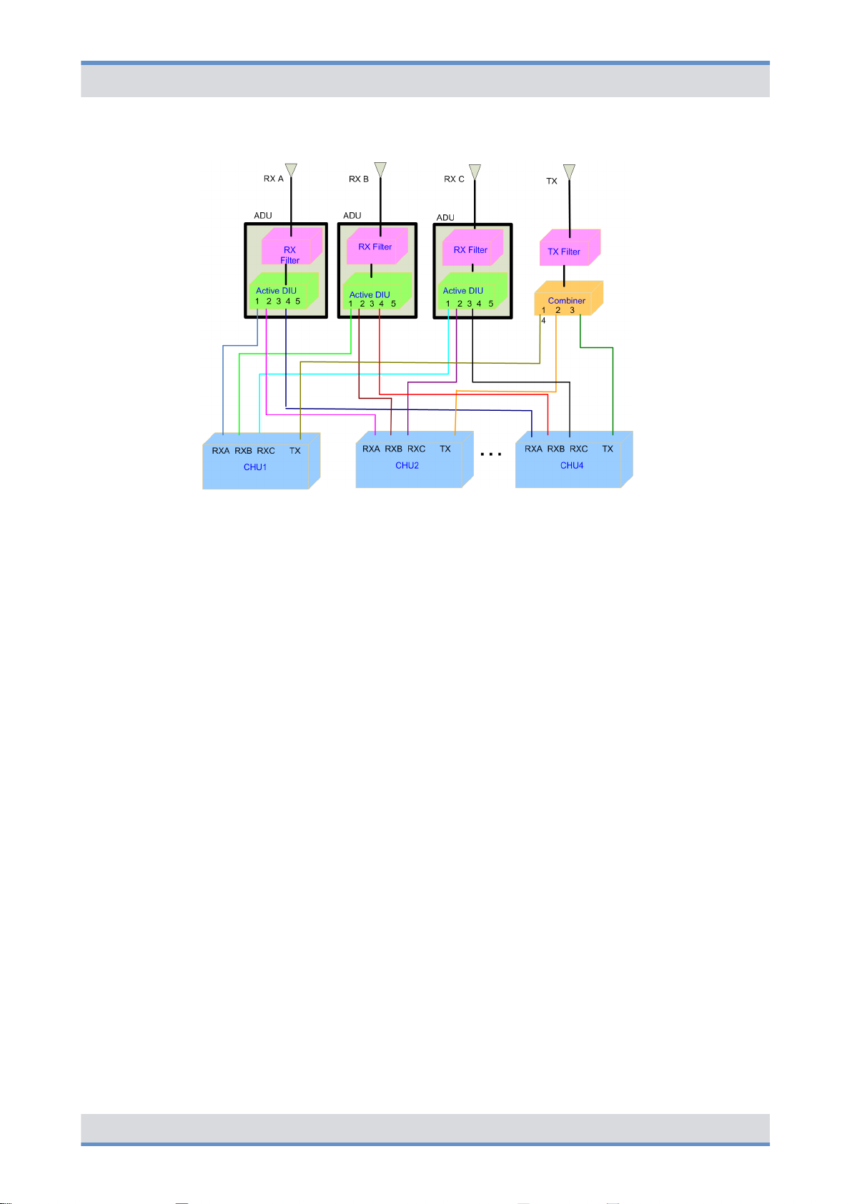
Product description
Redundancy options
DIB-R5 advanced
Figure 36: Antenna configuration with four CHUs and TX FILTER
3.5 Redundancy options
ACCESSNET-T IP provides numerous redundancy concepts to ensure the availability of
services and features reliably even in exceptional situations. The concept of designing
system functions, function blocks, network elements and connection routes redundantly,
may be required to ensure location reliability and system reliability. Location and system
reliability refers to the capability of the network to perpetuate the operation of the overall
system, even if one location or route drops out completely or partially (due to technical
failure, natural phenomena, acts of terrorism etc.).
The system technology allows flexible network structures and scalable redundancy solutions that account for the different requirements for availability and capacity within an
complete network.
If the DIB-R5 advanced should be isolated from the rest of the network, it still provides
most of its features in local fallback operation. Especially security-related features like
authentication and air interface encryption are supported. Hence, DIB-R5 advanced enables a fully functional fallback operation and full redundancy for the important components transceiver (CHU), control unit (BSCU) and voltage supply.
The following chapters describe the available redundancy options in conjunction with
DIB-R5 advanced:
nÄ Redundant main control channel (MCCH)
Ä
Transceiver redundancy
n
nÄ Controller redundancy
Ä
Fallback operation
n
nÄ Stand-alone operation
Ä
Redundant VAC voltage supply
n
nÄ Redundant connection to the transport network
nÄ Redundant synchronization (GNSS, PTP)
60 Operation Manual 90DIBR5advancedOM02 - 1.0
Page 61

DIB-R5 advanced
3.5.1 Redundant main control channel (MCCH)
Product description
Redundancy options> Fallback operation
The redundancy options can be combined with each other.
By redundant main control channels (MCCH) the operation of a base station is guaranteed even if the carrier with the MCCH drops out or should be disturbed.
If the carrier that provided the main control channel last drops out, an alternative carrier
will take on this task. The MCCH is thus transferred. This will maximally be repeated as
often as the number of carriers that are available at the base station. In this case, the
replacement carriers for the MCCH keep on sending on their original frequency, not on
the frequency of the failed carrier. This frequency change is useful especially when interfering carriers affect the MCCH frequency that was being used up to that point.
Irrespective of the number of carriers, each radio cell has only one MCCH, via which the
mobile stations receive information, e.g. on adjacent radio cells. As a rule, the first
channel of the first carrier of a base station is used as the MCCH, the three remaining
channels of that carrier and all the channels of all the other carriers are used as voice
channels or the Packet Data service. Redundant MCCH are enabled by default and apply
to all the base stations with more than one carrier.
3.5.2
3.5.3
3.5.4
Transceiver redundancy
To increase the system stability of carriers or to ensure the Base Station Function (BSF),
as many as two redundant transceivers can be used in one base station. If one transceiver fails, these spare transceivers ensure the radio coverage with the frequency of the
failed transceiver. Transceiver redundancy is mostly used in cases, in which only a few
frequencies are available.
Controller redundancy
The controller required for operating a base station can be designed redundantly. In this
case, two BSCUs (Base Station Controller Units) are used, whereby one BSCU is in
operation and the other is kept ready for operation (standby). In case of a failure of the
active BSCU or its ethernet connection, the standby BSCU is automatically switched to
active and takes over its function. This ensures continued operation of the base station.
Fallback operation
The radio coverage of base stations is also ensured if the base station loses the connection to an IP Node (IPN) with Switching Controller Function (SCF). In this case, the base
station changes to fallback operation. In fallback operation, the base station in its radio
cell still maintains the Base Station Function (BSF). Even in fallback operation, authentication and authorization validation are ensured since the corresponding subscriber data
are stored in the base station.
61Operation Manual 90DIBR5advancedOM02 - 1.0
Page 62

Product description
Redundancy options> Redundant VAC voltage supply
The connection to other network constituents is not possible in fallback operation, the following services and features, however, are available locally:
n Group calls
n Individual calls (semi-duplex and duplex calls)
n Transmission of SDS and status messages
n Class 2 and class 3 air interface encryption (encrypted voice and data communica-
tion)
n Authentication (with respect to the base station)
n Priority calls, emergency calls, pre-emptive priority calls
n Queue, depending on the priority level of the call
n Rejection of a call from/to an unknown subscriber
n Rejection with the reason "busy" if the subscriber is already making a call or the pri-
ority of the incoming call is minor
n Configurable call time limit
n Inactivity timer (ending semi-duplex calls after the configured inactivity time has
expired)
Fallback operation is the emergency operating mode of base stations in networks with
centralized switching architecture. The operating mode is signaled to the mobile stations
and taken into account by them for the cell selection.
DIB-R5 advanced
3.5.5
3.5.6
Stand-alone operation
The radio coverage of base stations with Switching Controller Function (SCF) in networks
with distributed switching architecture continues to be ensured if they lose the connection
to all other network constituents with SCF. In this case the base station switches to standalone operation.
In stand-alone operation, the base station in its radio cell will perpetuate the Base Station
Function (BSF) as well as all the other local services and gateways (Application Gateway
(AGW) and/or Packet Data Gateway (PGW)). As opposed to fallback operation, in standalone operation Call Detail Records (CDR) will still be generated.
Stand-alone operation is the emergency operating mode of base stations in networks with
distributed switching architecture. The operating mode is signaled to the mobile stations
and taken into account by them for the cell selection.Depending on the project requirements, the signaling can be switched off upon demand.
Redundant VAC voltage supply
For the reliable voltage supply, DIB-R5 provides two redundancy options for VAC voltage
supply to ensure operation of the base station at all times:
n
Ä
Redundant rectifier modules (Power Supply Module, PSM)
Ä
Redundant voltage supply feeds
n
Both redundancy options can be combined for the highest possible reliability.
62 Operation Manual 90DIBR5advancedOM02 - 1.0
Page 63

DIB-R5 advanced
3.5.6.1 Redundant rectifier modules (Power Supply Module, PSM)
3.5.6.2 Redundant voltage supply feeds
Product description
Redundancy options> Redundant synchronization (GNSS, PTP)
The voltage supply continues to be ensured through redundant rectifier modules (Power
Supply Module, PSM) and ensures the operation of DIB-R5 if one PSM should fail. The
active and the redundant PSMs are all in operation in this case and divide the load
among them. In case of a failure, the load on the remaining PSMs is increased accordingly.
In the combination with redundancy option "Redundant voltage supply feeds", two PSMs
each are supplied by one voltage supply feed.
The voltage supply continues to be ensured on site by the redundant voltage supply
feeds and secures the operation of DIB-R5 even if a feed should fail or fall below the
required voltage range. This is particularly meaningful in difficult environments in which,
for example, the infrastructure on site is unreliable. With this redundancy option, one
Power Distribution Module (PDM), two in case of redundancy, is always supplied by a
voltage supply feed.
If this redundancy option is selected, a second voltage supply feed must be taken into
account in the location planning.
3.5.7
3.5.8
Redundant connection to the transport network
With the redundant connection to the transport network, the connection to all network
components continues to be ensured in case of a failure of the IT infrastructure (e.g.
router).
Redundant synchronization (GNSS, PTP)
The clock and time signals required for the synchronization of base stations are being
obtained in parallel via a connected GNSS antenna and as an alternative via the Precision Time Protocol (PTP). If the satellite signal should no longer be available due to
external influences, a switch is automatically made to the network time.
63Operation Manual 90DIBR5advancedOM02 - 1.0
Page 64

Product description
Scope of delivery
3.6 Scope of delivery
DIB-R5 advanced
The DIB-R5 advanced is delivered in a 19" equipment rack, in case of more than four
CHUs in two 19" equipment racks. The scope of delivery varies depending on the variant.
The variants of DIB-R5 advanced are the result of the following properties:
n Voltage supply
n Combiner
n Number of transceivers
n Frequency range
n Redundancy options
Scope of delivery DIB-R5 advanced (per equipment or compact rack)
Designation Part number Number
DIB-R5 advanced 5503.xxxx.xx 1
RX FILTER 5502.0856.xx 1 to 3
Passive Divider Unit (PDU) 5502.0840.02 1 to 2*
DUPLEXER 5502.0862.xx 1
TX FILTER 5502.0879.xx 1
TETRA Channel Unit (CHU) 5502.0104.xx 1 to 4
Base Station Controller Unit (BSCU) 5502.0704.02 1 to 2
Interconnection Relay Unit (IRU) ‒ only in the case of
5502.0404.02 1*
two equipment or compact racks
Fan unit 5502.0604.02 1
Power Supply Unit (PSU) ‒ with VAC voltage supply 5502.1020.00 1
Power Supply Module (PSM) ‒ with VAC voltage supply 5502.0910.00 1 to 4
Cavity combiner 5502.0940.00 1
Backplane 5502.0656.02 1
AC Power Distribution Module (APDM) ‒ with V
AC
5502.0579.xx 1 to 2
voltage supply
DC Power Distribution Module (DPDM) ‒ with V
DC
5502.0585.xx 1
voltage supply
Alarm/connection box (connection panel) 5502.0640.02 1
GNSS splitter 5505.0962.00 1
n xx is variant-specific and, for example, dependent on the frequency range or
voltage supply
n * used only in the case of two equipment or compact racks
64 Operation Manual 90DIBR5advancedOM02 - 1.0
Page 65

DIB-R5 advanced
4 Operation
Operation
Safety measures and prerequisites
This chapter describes the procedure for the proper operation of the product at its location.
The work steps listed in the following table must be performed for the operation of the
product.
Overview of work steps to be performed (operation)
Work steps Described in
Ä
Switching on the DIB-R5 advanced
Ä
Function tests and
operating surveillance
Ä
Checking operating states
Ä
Chapter 4.2 “Switching on
the DIB-R5 advanced”
on page 66
Ä
Chapter 4.3.3 “Checking
operating states” on page 70
Ä
Checking the availability
Ä
Function tests and oper-
ating surveillance GNSS
4.1 Safety measures and prerequisites
The following security measures and prerequisites must be observed for all activities:
n The site must be prepared in compliance with the document "DIB-R5 advanced Site
Requirements".
n The product must have been set up and connected according to the document
"DIB-R5 advanced Installation Manual".
n The product must have been configured according to the document
"DIB-R5 advanced Configuration Manual".
n The DIB-R5 advanced may be set up and commissioned only of the required ambient
Ä
conditions are met at all times, refer to
n The safety regulations must be considered at all times, refer to chapter
“Safety regulations” on page 13.
n Observe all other activity-based security measures and prerequisites in the work
steps in this chapter.
Table “Ambient data” on page 66.
Ä
Chapter 4.3.4 “Checking
the availability” on page 72
Ä
Chapter 4.3.6 “Function
tests and operating surveillance GNSS” on page 74
Ä
Chapter 2
Ambient data
Operation Temperature range
(normal)
Temperature range
(extreme, as per
EN 300 394)
+5 °C to +45 °C (+41 °F to
+113 °F)
-30 °C to +55 °C (-22 °F to
+131 °F)
65Operation Manual 90DIBR5advancedOM02 - 1.0
Page 66

Operation
Switching on the DIB-R5 advanced
DIB-R5 advanced
Relative humidity 5 % to 85 % (non-con-
densing)
Degree of protection IP20
Altitude for operation max. 4000 m (13 123 ft)
Transport
(in original packaging)
Storage
(in original packaging)
Temperature range -40 °C to +70 °C (-40 °F to
Temperature range -40 °C to +70 °C (-40 °F to
4.2 Switching on the DIB-R5 advanced
The product is switched on via an on/off switch on the connection and control panel. After
switching on the DIB-R5 advanced, the integrated hardware components will automatically start up. Connections will be enabled. All the components are started up after
approx. three to five minutes.
To switch on the product, the connections must have been made properly and the voltage
source at the installation site must have been switched on already. The procedure for
switching on the voltage source depends on the circumstances at the respective installation site.
Several on/off switches with redundant voltage supply feeds
With redundant voltage supply feeds (optional), the DIB-R5 advanced features two on/
off switches and two separate voltage sources, if necessary. Each of them has to be
switched on for commissioning the product.
+158 °F)
+158 °F)
Switching on the DIB-R5 advanced
Preparation:
n The DIB-R5 advanced must be connected with the earthing system of the voltage
source at the installation site.
n All required connecting cables as well as antennas must be connected.
n The alarm contacts must be wired.
1. Switch on the voltage source via the corresponding equipment at the installation
site.
2. Set the on/off switch to the switch position "ON", refer to Figure 8.
The integrated hardware components start up.
ð
➔ You have successfully switched on the DIB-R5 advanced.
66 Operation Manual 90DIBR5advancedOM02 - 1.0
Page 67

DIB-R5 advanced
4.3 Function tests and operating surveillance
Operation
Function tests and operating surveillance
Performing function tests
Following the execution of the work steps, it is recommended to perform function tests in
order to ensure the proper mode of operation of the product.
The function tests are described in Ä Chapter 4.3 “Function tests and operating surveillance” on page 67.
After all the tasks have been performed on the product that have effects on the product
and/or its components, the proper operation of all the integrated network and hardware
components should be tested. We recommend logging the results of the test.
In addition, it is recommended to perform the tasks described in the following sections in
regular intervals during the operation.
The following table provides an overview of work steps for testing the function and for
operational monitoring.
Overview of work steps (function tests and operating surveillance)
Work steps Described in
Ä
Connecting the service computer
Ä
Checking operating
states
Ä
Checking operating states (via
LEDs)
Ä
Checking operating states
(audible check)
Ä
Checking operating states (via
the NMC-511 FaultManager)
Ä
Chapter 4.3.2 “Connecting the service
computer” on page 69
Ä
Chapter 4.3.3.1
“Checking operating
states (via LEDs)”
on page 70
Ä
Chapter 4.3.3.2
“Checking operating
states (audible check)”
on page 70
Ä
Chapter 4.3.3.3
“Checking operating
states (via the
NMC-511 FaultManager)” on page 71
Ä
Checking the availability
Ä
Chapter 4.3.4
“Checking the availability” on page 72
67Operation Manual 90DIBR5advancedOM02 - 1.0
Page 68

Operation
Function tests and operating surveillance > Connecting the service computer
Work steps Described in
Ä
Checking standby carriers ‒ optional
Ä
Function tests and operating surveillance GNSS
4.3.1 Work equipment for function tests
The following table provides an overview of the work equipment for function tests and
operating surveillance.
DIB-R5 advanced
Ä
Chapter 4.3.5
“Checking standby carriers ‒ optional”
on page 73
Ä
Chapter 4.3.6 “Function tests and operating
surveillance GNSS”
on page 74
Overview of work equipment (function tests and operating surveillance)
Work step Work equipment
Checking operating states via the NMC-511
FaultManager
Checking the reachability of network elements
Function tests and operating surveillance
GNSS
Checking standby carriers NMC-511 FaultManager
4.3.2 Connecting the service computer
The service computer may be any computer that meets the system requirements.
The system requirements for the service computer are described in the related product
documents, refer to the following table.
n configured NMC computer
n straight through ethernet cable
n NMC-511 FaultManager
n configured NMC or service computer
n straight through ethernet cable
n configured NMC computer
n NMC-511 FaultManager
n GNSS antenna(s)
n GNSS antenna cable
Required product documents
Product Document type Described in
Service computer Configuration Manual Chapter 2
68 Operation Manual 90DIBR5advancedOM02 - 1.0
Page 69

DIB-R5 advanced
Operation
Function tests and operating surveillance > Checking operating states
The service computer is connected via the connection panel. The ethernet interface
"SW1" is used by default for this purpose; with controller redundancy, the ethernet interface "SW2" is additionally used for the connection to the second BSCU. During the connection, the service computer is automatically assigned a local service IP address for the
respective DIB-R5 advanced.
Connecting the service computer
Preparation:
n The working appliances must be available, refer to Ä Chapter 4.3.1 “Work equipment
for function tests” on page 68.
n The service computer must have been started.
n The DIB-R5 advanced must be switched on.
4.3.3
Figure 37: Connections of the service computer (local)
Connect the ethernet cable to the connector on the DIB-R5 advanced (refer to
Figure 37) and to the ethernet port of the service computer.
➔ You have successfully connected the service computer.
Checking operating states
You can check manually whether the product and the hardware components installed
operate properly on the respective hardware component, if indicators are available, or via
a connected NMC-511 FaultManager network management client.
The following table provides an overview of the procedures for checking operating states
of the DIB-R5 advanced.
69Operation Manual 90DIBR5advancedOM02 - 1.0
Page 70

Operation
Function tests and operating surveillance > Checking operating states
Overview of the procedures for checking operating states
Work step Described in
Ä
Checking operating states (via LEDs)
Ä
Checking operating states (audible
check)
Ä
Checking operating states (via the
NMC-511 FaultManager)
4.3.3.1 Checking operating states (via LEDs)
The following table provides an overview of hardware components whose LEDs can be
checked.
Ä
Chapter 4.3.3.1 “Checking operating
states (via LEDs)” on page 70
Ä
Chapter 4.3.3.2 “Checking operating
states (audible check)” on page 70
Ä
Chapter 4.3.3.3 “Checking operating
states (via the NMC-511 FaultManager)”
on page 71
DIB-R5 advanced
Checking operating states (via LEDs)
Hardware component Described in
TETRA Channel Unit (CHU)
Base Station Controller Unit (BSCU)
Fan unit
Power Supply Module (PSM) ‒ with V
voltage supply
4.3.3.2 Checking operating states (audible check)
Upon switching on the DIB-R5 advanced, the fans briefly rotate at high speed and are
then adjusted according to the room temperature. No grinding or rattling noise should be
present at this time.
Checking operating states (audible check)
Preparation:
AC
Ä
Table “Legend: Indicators (LEDs) of the
CHU” on page 44
Ä
Table “Legend: Indicators (LEDs) of the
BSCU” on page 46
Ä
Table “Legend: Indicators (LEDs) of the
fan unit” on page 51
Ä
Table “Legend: PSM (front view)” on
page 35
n The DIB-R5 advanced must be switched on.
n The front equipment rack door must be open.
Check whether grinding or rattling noise can be heard.
If the corresponding noises can be heard, you must perform a fault analysis.
ð
➔ The function test has been completed.
70 Operation Manual 90DIBR5advancedOM02 - 1.0
Page 71

DIB-R5 advanced
4.3.3.3 Checking operating states (via the NMC-511 FaultManager)
Operation
Function tests and operating surveillance > Checking operating states
Using the NMC‑511 FaultManager network management client, faults occurring in an
ACCESSNET-T IP network can be detected and localized rapidly. This facilitates prompt
fault elimination.
All network constituents and connections of an ACCESSNET-T IP are monitored via the
NMC-511 FaultManager. Operating states and faults are detected by the network management system and visualized via the connected workstations, on which the NMC-511
FaultManager is installed and enabled.
The NMC-511 FaultManager displays the operating states and faults of the network constituents in the respective network in an alarm status list. This makes permanent network
monitoring possible.
Checking the operating statuses via the NMC-511 FaultManager requires an NMC computer that is configured accordingly, with installed NMC-511 FaultManager that is connected with the ACCESSNET-T IP.
Besides checking the respective hardware and software components, the application
connections between the network elements should also be checked to ensure the correct
connection.
Checking the operating state (via the NMC-511 FaultManager)
Preparation:
n The NMC-511 FaultManager must have been started.
1. Use the Equipment view of the NMC-511 FaultManager to navigate to the corre-
sponding network constituent (hardware or software component).
2. Ensure that the corresponding network constituent is shown in green in the
Equipment view of the NMC‑511 FaultManager.
If the respective network constituent is shown in red, you must perform a fault
ð
analysis, refer to NMC-511 FaultManager User Manual.
3. Check whether a predecessor alarm status is displayed for the respective network
constituent which displays a fault that may already have existed.
If the predecessor alarm status is shown in red, it is recommended to generate
ð
a report via the Analysis perspective.
4. Navigate to the Service perspective and check whether corresponding services are
shown in green.
If services are shown in red, you must perform a fault analysis, refer to
ð
NMC-511 FaultManager User Manual.
5. In the Equipment view, check whether all application connections are displayed in
green.
If application connections are shown in red, you must perform a fault analysis,
ð
refer to NMC-511 FaultManager User Manual.
➔ The function test has been completed.
71Operation Manual 90DIBR5advancedOM02 - 1.0
Page 72

Operation
Function tests and operating surveillance > Checking the availability
4.3.4 Checking the availability
After network elements have been connected with an existing switch or router at the site,
it must be checked whether the respective network element can be reached via the IP
address of the BSCU. The NMC-511 FaultManager is used to check whether the IP
address can be reached. If this should not be possible, the ping command should be
used to check whether it can be reached.
IP addresses of installed components
The configured IP addresses can be displayed via the NMC-511 FaultManager in the
Properties view and are also documented in the project-specific documentation.
Checking the availability
Preparation:
n The NMC or service computer must have been connected with the transport network.
n The NMC-511 FaultManager must have been started.
1. Check the status of the connections in the Visualization view of the NMC-511
FaultManager.
DIB-R5 advanced
Optional work step
The work steps described below are required only if the NMC-511 FaultManager cannot
check whether the network element can be reached or if no connection exists.
2. Use the Equipment view of the NMC-511 FaultManager to navigate to the corre-
sponding network constituent (hardware or software component).
3. Change to the Properties view and record the required IP address.
4.
Click on “Windows Start menu è Programs è Accessories è Command prompt”.
The command prompt is displayed.
ð
72 Operation Manual 90DIBR5advancedOM02 - 1.0
Page 73

DIB-R5 advanced
Operation
Function tests and operating surveillance > Checking standby carriers ‒ optional
5. Enter the following command to check the reachability of the network element:
ping <xxx>
<xxx> corresponds to the IP address of the respective component within the
DIB-R5 advanced.
The following output is displayed (example):
ð
C:\Users\User>ping <xxx>
Ping is executed for <xxx> with 32 bytes of data:
Response from <xxx>: Bytes=32 Time<1 ms TTL=63
Response from <xxx>: Bytes=32 Time<1 ms TTL=63
Response from <xxx>: Bytes=32 Time<1 ms TTL=63
Ping statistic for <xxx>:
Packets: Sent = 4, Received = 4, Lost = 0 (0% loss),
Approx. time information in milliseconds: Minimum = 0 ms,
maximum = 0 ms, average = 0 ms
4.3.5
➔ You have successfully checked the availability.
Checking standby carriers ‒ optional
The DIB-R5 advanced optionally provides the redundancy option "Transceiver redundancy" with up to two standby carriers that can replace two carriers that have dropped
out.
As a preventive maintenance measure, it is recommended to check the function of the
Ä
standby carriers at regular intervals, refer to
on page 83. This is done via the NMC-511 FaultManager.
Required product documents
Product Document type Described in
NMC-511 FaultManager User Manual Chapter 4
Chapter 7.2 “Periodical visual inspections”
73Operation Manual 90DIBR5advancedOM02 - 1.0
Page 74

Operation
Function tests and operating surveillance > Function tests and operating surveillance GNSS
Checking standby carriers
Preparation:
n The respective DIB-R5 advanced must be in operation.
n The NMC-511 FaultManager must have been started.
1. Select the corresponding operational carrier in the Equipment or Visualization view
of the NMC-511 FaultManager.
2. Right-click on the selected carriers to display the context menu.
The context menu will be displayed.
ð
Availability of maintenance functions
Not all the maintenance functions can be used for all the network constituents.
Maintenance functions that cannot be performed for the time being will be displayed in grey and cannot be selected.
DIB-R5 advanced
4.3.6
3. In the context menu, click on the System blocking maintenance function.
The corresponding carriers are excluded from functional operation and identi-
ð
fied in the Equipment view with the "Person" icon (operationally blocked by the
user).
Existing standby carriers are enabled.
4. In the NMC-511 FaultManager, check in the Equipment view of the Equipment
perspective whether the standby carriers become active and do not report alarm.
5. Unblock any blocked operational carriers after at least 5 minutes with the System
release maintenance function.
The system blocking of operational carriers has been revoked.
ð
Standby carriers are switched back to their original status.
➔ You have successfully checked the standby carriers.
Function tests and operating surveillance GNSS
The following chapters describe procedures for function tests and the operational monitoring concerning the GNSS functionality of the DIB-R5 advanced.
4.3.6.1 Checking the installation site of the GNSS antenna
To prevent damage, e.g. caused by insufficient guarding and/or fastening, the installation
site of the GNSS antenna should be checked following the installation of the GNSS
antenna.
74 Operation Manual 90DIBR5advancedOM02 - 1.0
Page 75

DIB-R5 advanced
Function tests and operating surveillance > Function tests and operating surveillance GNSS
Operation
Checking the installation site of the GNSS antenna
Preparation:
n The installation and connection of the GNSS antenna must have been completed.
1. Check the installation site of the GNSS antenna for proper condition, such as the
n fastening of the antenna mast,
n fastening of the GNSS antenna,
n cable routing.
Circumferential range of vision (angle of unobstructed visibility of the sky) of the
GNSS antenna.
A good circumferential range of vision (angle of unobstructed visibility of the sky
according to the recommendations of the manufacturer) must be maintained to ensure
proper reception of the GNSS antenna. The angle of the GNSS antenna supplied is 90°.
When using a third-party GNSS antenna, heed the corresponding documentation supplied with the GPS antenna.
2. Check the circumferential range of vision of the GNSS antenna.
➔ The visual inspection has thus been completed.
4.3.6.2 GNSS operational monitoring (via NMC-511 FaultManager)
The function of the GNSS receiver and the detectable GNSS satellites are monitored by
the DIB-R5 advanced based on the GNSS data received.
Using the NMC‑511 FaultManager network management client, faults occurring in an
ACCESSNET-T IP network can be detected and localized rapidly. This facilitates prompt
fault elimination.
All network constituents and connections of an ACCESSNET-T IP are monitored via the
NMC-511 FaultManager. Operating states and faults are detected by the network management system and visualized via the connected workstations, on which the NMC-511
FaultManager is installed and enabled.
The NMC-511 FaultManager displays the operating states and faults of the network constituents in the respective network in an alarm status list. This makes permanent network
monitoring possible.
The procedures for this purpose are described in corresponding documents, refer to the
following table.
Required product documents
Product Document type
NMC-511 FaultManager User Manual
75Operation Manual 90DIBR5advancedOM02 - 1.0
Page 76

Operation
Function tests and operating surveillance > Function tests and operating surveillance GNSS
In the NMC-511 FaultManager the operating conditions and errors on network constituents are represented by so-called alarm objects.
Alarm objects provide alarms/statuses for properties of hardware and software components. In addition, alarm objects contain information that aids in the context of fault management in the evaluation, localization and removal of errors.
GNSS module – Possible messages
No. Alarm object (NMC-511 FaultManager) Description
1 GNSS antenna status Status of the GNSS antenna con-
nection
2 Communication (GNSS) Status of communication with the
GNSS module
DIB-R5 advanced
76 Operation Manual 90DIBR5advancedOM02 - 1.0
Page 77

DIB-R5 advanced
5 Service interruption
Service interruption
Shutting down hardware components
This chapter describes the procedure for the service interruption of the product.
A service interruption may be required in the following cases:
n Work on an open equipment rack
n End of operation
n Malfunction
n The integration of further components,
Possible restrictions for the operation
If a product is taken out of service, the operation of other parts in the radio network may
be impaired as well. Discuss this problem with your service partner to obtain detailed
information on risks and on recommended procedures.
5.1 Shutting down hardware components
The installed hardware components CHU and BSCU operate with different software components that should be shut down properly. For this reason, these hardware components
must be shut down before switching off the DIB-R5 advanced.
The following table provides an overview of the order in which the hardware components
should be shut down.
Shutting down hardware components (order)
Order Hardware component
1 BSCU (standby) ‒ optional
With redundant BSCUs, the BSCU in standby operation must be shut
down first to prevent a switchover of the BSCUs. The operating status
of the BSCU is indicated via LEDs, refer to
tors (LEDs) of the BSCU” on page 46.
2 BSCU (operational)
Shutting down the CHU
When shutting down the BSCUs, all installed CHUs are also shut down automatically.
The CHUs do not have to be shut down individually except for service and maintenance
purposes.
Ä
Table “Legend: Indica-
77Operation Manual 90DIBR5advancedOM02 - 1.0
Page 78

Service interruption
Switching off the DIB-R5 advanced
Shutting down hardware components
Press the Power button on the hardware component to shut it down.
The software components are being shut down.
ð
The indicators (LEDs) go out after approx. 5 to 20 seconds.
The hardware component is properly shut down if the "RUN" LED is off.
➔ You have successfully shut down the hardware components.
5.2 Switching off the DIB-R5 advanced
The procedure for switching off the DIB-R5 advanced is described below.
DIB-R5 advanced
Several on/off switches with redundant voltage supply feeds
With redundant voltage supply feeds (optional), the DIB-R5 advanced features two on/
off switches and two separate voltage sources, if necessary. Each of them has to be
switched off for the service interruption of the product.
Switching off the DIB-R5 advanced
Preparation:
n The installed hardware components must have been shut down, refer to
Ä
Chapter 5.1 “Shutting down hardware components” on page 77.
1. Set the on/off switch to the switch position "OFF", refer to Figure 8.
The integrated hardware components are switched off.
ð
2. Switch off the voltage source at the location. Alternatively you can switch off the
fuse of the sub-distribution.
Risk of electric shock
Ensure by means of switch interlock that a source of electrical power cannot be
switched on unintentionally by an unauthorized third person.
3. Check whether all LED displays are inactive.
➔ You have successfully switched off the DIB-R5 advanced.
78 Operation Manual 90DIBR5advancedOM02 - 1.0
Page 79

DIB-R5 advanced
Service interruption
Switching off the DIB-R5 advanced
Recommissioning
The required recommissioning will be pointed out in the corresponding chapters.
79Operation Manual 90DIBR5advancedOM02 - 1.0
Page 80

Service interruption
Switching off the DIB-R5 advanced
DIB-R5 advanced
80 Operation Manual 90DIBR5advancedOM02 - 1.0
Page 81

DIB-R5 advanced
6 Recommissioning
Recommissioning
To recommission the product, you either have to connect the equipment rack to the
voltage source or switch it on, depending on the connection variant.
Recommissioning
For a new commissioning of DIB-R5 advanced, proceed as described in Ä Chapter 4.2
“Switching on the DIB-R5 advanced” on page 66.
81Operation Manual 90DIBR5advancedOM02 - 1.0
Page 82

Recommissioning
DIB-R5 advanced
82 Operation Manual 90DIBR5advancedOM02 - 1.0
Page 83

DIB-R5 advanced
7 Maintenance
7.1 Maintenance tasks
Maintenance
Periodical visual inspections
To ensure the proper operation of products, maintenance tasks and periodical visual
inspections are required.
The products have been designed for permanent and unsupervised operation. Nevertheless you have to perform checks every now and then. When doing so, you can detect and
remove dirt in the vicinity of or within equipment racks, so the air supply and heat dissipation of the products is always ensured.
The current status of the hardware components can be monitored via a connected
NMC-511 FaultManager. For more information on the NMC-511 FaultManager, please
refer to the product documentation of the NMC-511 FaultManager.
Soiling may impair the air supply and the heat dissipation and thus affect the operation.
For this reason, the activities listed below should be performed in the interval specified.
Maintenance tasks
Task/s Interval/s
Replace the fan after 30,000 operating hours
Replace the air filter pad Depends on the environmental conditions
Early fan replacement
Independent of the ambient data at the installation site, the fan may have to be replaced
earlier. For this reason, please comply with the following recommended visual inspections and intervals.
7.2 Periodical visual inspections
The table below lists the recommended tasks for maintaining the products. The visual
inspections should be performed in the intervals specified to be able to respond in due
time, e.g. in the case of changes at the location that may result in improper operation.
We recommend logging the results of the test.
83Operation Manual 90DIBR5advancedOM02 - 1.0
Page 84

Maintenance
Periodical visual inspections
Activities and intervals for visual inspections
Task/s Interval/s
DIB-R5 advanced
Site inspection based on the document "DIB-R5 advanced Site
Requirements", such as inspecting the:
n Grounding equipment
n Voltage supply connector
n TETRA antennas
n Installation location of the GNSS antenna
n Condition and fit of all supply lines, renew if necessary
n Connections between two DIB-R5 advanced ‒ only in the case
of a CHU expansion
Check the condition of the product with respect to:
n Readiness for operation
n Dirt and dust accumulations on and in the equipment rack,
remove if necessary
n Degree of contamination of contact pins, remove dirt if neces-
sary
n Check the fan unit for proper operation: Replace the air filter
pad as required
Check function of external alarms – if wired Once every year
Checking standby carriers – if available Once every year
n Upon location
changes
n Once every
year
Once every year
Shorter intervals may be required
Depending on the respective environmental conditions at the site of the product, shorter
intervals may be required.
84 Operation Manual 90DIBR5advancedOM02 - 1.0
Page 85

DIB-R5 advanced
8 Troubleshooting
Troubleshooting
Troubleshooting via the network management system (NMS)
The NMC-511 FaultManager can be used to detect faults within the ACCESSNET-T IP.
This is done via a NMC computer that has been configured accordingly.
The troubleshooting via the NMC-511 FaultManager should be performed prior to the
troubleshooting on site (e.g. at locations of network elements. It can provide information
whether a site must actually be visited.
The following table lists possible problems, causes and troubleshooting measures.
Troubleshooting
Problem Possible cause Troubleshooting
Base station cannot be
reached/switched on
On/off switch in switch position
"OFF"
Voltage supply at location not
operational
Cable connection defective Check internal wiring
APDM/DPDM defective Check fuse
PSU/PSM defective ‒ with V
voltage supply
Set on/off switch to switch position "ON"
Check fuse
Check distribution box or mains socket
Check voltage supply cable
Check cables
Check wiring
Carry out the visual inspection
Check operating state via
NMC-511 FaultManager
Check operating states via LEDs
AC
Check operating state via
NMC-511 FaultManager
Connection to transport network defective (stand-alone or
fallback operation)
Ethernet connection defective Check operating state via
NMC-511 FaultManager
Check reachability with ping
Cable connection defective Check operating state via LEDs on
switch/router
Check internal wiring
Check ethernet cable
85Operation Manual 90DIBR5advancedOM02 - 1.0
Page 86

Troubleshooting
Problem Possible cause Troubleshooting
Switch/router defective Check operating state via LEDs on
switch/router
DIB-R5 advanced
Call setup/registration not possible
Transmitting/receiving antenna
Check antenna
defective
Cable connection defective Check wiring of antenna(s) incl. antenna
cable
Check internal wiring
Carrier disabled Check status of carrier in the NMC-511
FaultManager
Carrier incorrectly configured Check configuration in the NMC-515
ConfigurationManager
Carrier defective Check status of carrier in the NMC-511
FaultManager and replace as required
No subscriber data available
on the base station
Check status in the NMC-511 FaultManager and, if necessary, in the NMC-515
ConfigurationManager
Subscriber unknown Check subscriber configuration in the
No authorization for call serv-
NMC-512 SubscriberManager
ices
Mobile station incorrectly con-
Check configuration of mobile station
figured
Mobile station defective Check mobile station
No GNSS signal GNSS antenna defective Check antenna
No unobstructed visibility of
the sky
Check installation location of the GNSS
antenna
Cable connection defective Check plug connections and antenna
cable
BSCU/CHU/HCU not ready for
operation
Electrical connection to backplane defective
PSU/PSM defective ‒ with V
Install insert correctly
Check PSU/PSM
AC
voltage supply
"ALM" LED is on Checking operating state in the NMC-511
FaultManager
Insert defective, e.g. BSCU,
CHU, HCU
Electrical connection to backplane defective
Check connection to backplane
Voltage supply missing Check voltage supply
Fan unit not (completely)
operational
Electrical connection to backplane defective
PSU/PSM defective ‒ with V
Check connection to backplane
Check PSU/PSM
AC
voltage supply
86 Operation Manual 90DIBR5advancedOM02 - 1.0
Page 87

DIB-R5 advanced
Problem Possible cause Troubleshooting
"ALM" LED is on Checking operating state in the NMC-511
FaultManager
"FAN 1-6" LED flashes Checking operating state in the NMC-511
FaultManager
Check fan
Troubleshooting
87Operation Manual 90DIBR5advancedOM02 - 1.0
 Loading...