

Page 1
Technical Data
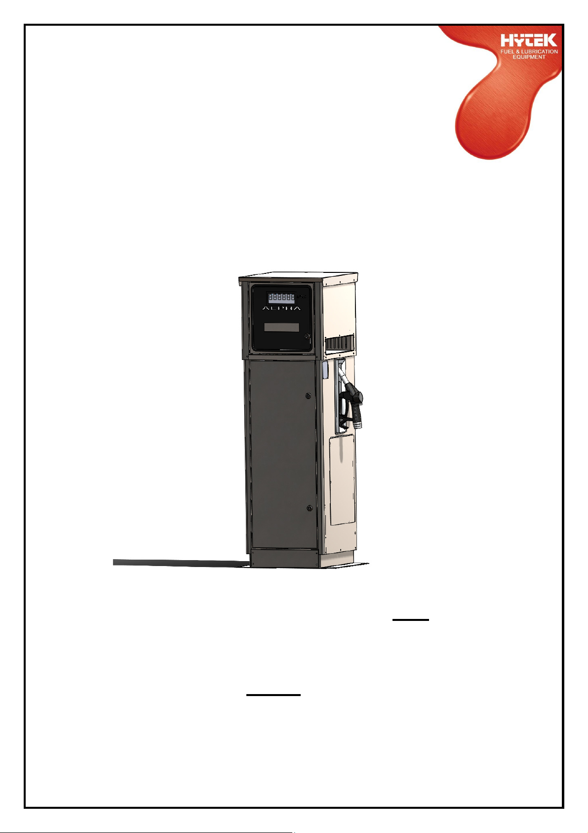
ALPHA ATEX APPROVED
PETROL PUMP
Applies to the following models only:
-ALPHA/50P -ALPHA/70P
Please read carefully before commencing installation
Registered Office: HYTEK (GB) LIMITED, Delta House, Green Street, Elsenham, Bishop’s Stortford
CM22 6DS UK. Registered in England No. 1915382
Tel: +44 (0) 1279 815 600 Fax: +44 (0) 1279 812 978 email: [email protected]
Web: www.hytekgb.com
S855/2
Page 2

ENVIRONMENTAL INFORMATION
European Directive 2012/19/EU requires that the equipment
bearing this symbol on the product and/or its packaging must
not be disposed of with unsorted municipal waste. The symbol
indicates that this product must be disposed of separately from
regular household waste streams. It is your responsibility to
dispose of this and other electric and electronic equipment via
designated collection facilities appointed by the government or
local authorities.
PRODUCT DESCRIPTION
This pump is ATEX certified to dispense petrol or other liquids
classed as category 1, 2 or 3 in accordance with European
Regulation No. 1272/2008. It bears the following certification
marking and number:
MANUFACTURED TO: EN13617-1
CERTIFICATE NO: CML 17ATEX9254
II
II
2 G
2503
IIII
IMPORTANT WARNING NOTES
1. On above ground storage tanks an angle check valve fitted
with the appropriate spring or pressure regulating valve must
be fitted at the tank outlet to prevent loss of fuel under gravity
in the event of vandalism or accidental damage.
2. This pump must only be used to dispense diesel or other
liquids classed as category 1, 2 or 3 in accordance with
European Regulation No. 1272/2008.
3. Installation of this equipment and its associated tank, pipe
work and fittings should only be carried out by qualified fuel
installation engineers.
S855/2
Page 3

4. The installation must be carried out in accordance with the
requirements of EN 60079-14 the latest relevant electrical and
local authority regulations and standards.
5. It must not be used with other liquids or for other applications.
We will accept no warranty claims or liability if it is used for
other liquids or applications.
CALIBRATION
The meter on this pump unit must be calibrated electronically to
ensure accuracy and reliability.
S855/2
Page 4

INSTALLATION INSTRUCTIONS
1. Check you have the following items:
1 off Alpha pump
1 off delivery hose
1 off front door key
2. Open the front panels using the key provided.
3. Remove the rear panels, if necessary, and store safely.
MOUNTING
4. Bolt the pump to a raised firm level foundation, at least
150mm in height, by means of the four 14 mm diametermounting holes provided. Locate the drip tray between the
pump base and the foundation with the lips around the holes
facing upwards.
NB: When the drip tray is fitted to the pump it must be sealed
to its foundation, with a suitable elastomeric substance, to
prevent leaked fuel "wicking" back underneath the pump. To
maintain the environmental integrity of the drip tray any
possible leak path through the pump mounting holes or the
cable and pipe entry holes must also be sealed.
S855/2
Page 5

PIPEWORK
5. Connect the 11/2” diameter pipe from the tank to the suction
inlet flexible connector of the pump. The inlet thread of the
flexible connector flange is 11/2” BSP taper female. Seal the
joints with a suitable thread sealing compound. The pipe work
must be sealed to the drip tray (if fitted) to ensure no leaking
fuel can flow underground. An alternative pipe work entry
point, for above ground pipe work, is provided at the rear of
the pump base. Push out the plastic cover plate if required.
NB:On above ground tanks an angle check valve fitted
with the appropriate spring or an anti-syphon valve must
be fitted in the suction line to prevent spillage or leakage
in the event of damage.
6. Connect the delivery hose and selected ATEX approved
nozzle to the pump outlet in accordance with the instructions
supplied with the individual components. Ensure the nylon
hose-sealing washers are in place on the hose end. It should
be hand tight plus a quarter turn.
S855/2
Page 6

ELECTRICAL
7. Remove the covers from the junction box.
8. Connect a constant 220/240V AC 50 Hz supply, fused at 16
amps, to the terminal block in the junction box as shown on
the wiring details diagram.
NB:The Alpha pump must have a continual 220/240V AC
supply, even when not in use
9. If the Alpha is to be operated in conjunction with a key/card
system, remove the link in the junction box (shown on the
Alpha Installation Wiring Diagram) and connect so that the
control system makes and breaks the connection.
Make connection - Pump on
Break connection - Pump off
Alternatively remove the link and connect a switched live
supply (230V AC 16A max.) to terminal 4 (shown on the Alpha
Installation Wiring Diagram)
Live supply switched on - Pump on
Live supply switched off - Pump off
10. A pulse output for connection to key/card systems is available
from the separate terminals located in the junction box. This is
a passive contact giving 10 or 100 pulses per litre. Contact
ratings are as follows:
Maximum current - 0.25 amps
Maximum voltage - 50 volts
Maximum power - 5 VA
11. Ensure all the terminal screws are tight and replace the
junction box covers.
S855/2
Page 7

INSTRUCTIONS FOR USE
1. Remove the nozzle from the holster.
2. Place the nozzle spout in the fuel tank.
3. Squeeze the nozzle trigger to dispense fuel.
On completion of the delivery release the trigger and replace
the nozzle in the holster.
S855/2
Page 8

MAINTENANCE
The Alpha should require minimum maintenance in normal regular
use, but as with all mechanical apparatus regular servicing will
prolong its life and ensure maximum efficiency & reliability.
The following should be carried out every 12 months or 1 million
litres which ever comes first.
-
Isolate power supply
-
Inspect & clean or replace pump filter
-
Inspect & clean or replace nozzle filter
-
Inspect & replace if necessary the V-belt
-
Check motor pulley grub screw is tight
-
Re-calibrate electronic display
S855/2
Page 9
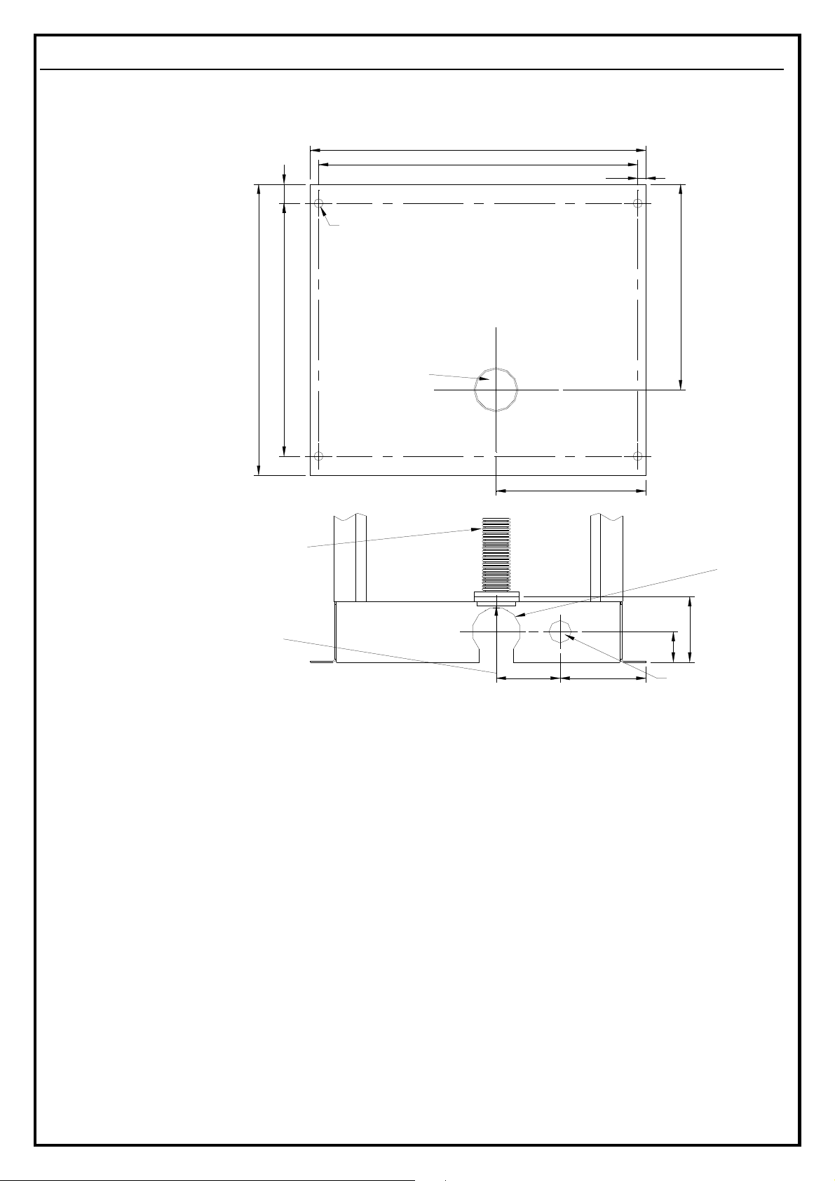
ALPHA BASE AND SUCTION CONNECTION DIAGRAMS
ALL DIMENSIONS IN MM
BASE VIEW FROM
ABOVE
REAR VIEW
1 1/2" STAINLESS STEEL FLEXIBLE
CONNECTOR (SUPPLIED AS STANDARD)
1 1/2" BSP TAPER FEMALE
THREADED STANDARD
TRIANGULAR SUCTION
WITH SUCTION HOLE
460
FLANGE ALIGNED
IN BASE
526
500
32396
FOUR 15MM DIA.
MOUNTING HOLES
SUCTION INLET
FRONT
LOCATION
215
82
133
13
340
76.5MM DIA.
ALTERNATIVE
SUCTION HOLE
SLOTTED TO
BOTTOM OF
BASE
105
44
22MM DIA. ALTERNATIVE
CABLE ENTRY HOLE
S855/2
Page 10
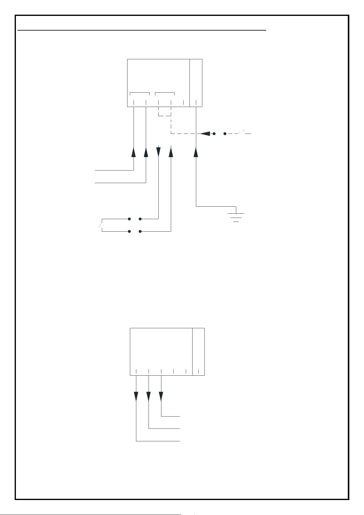
ALPHA INSTALLATION WIRING DIAGRAM
MAINS / 230VAC JUNCTION BOX CONNECTIONS
CONSTANT SUPPLY
220 / 240V AC
FUSE - 16A
KEY/CARD CONTROL
SYSTEM RELAY
L
N
220/240V AC
16A MAX
220-240V
INPUT
L
N
132
AUTH.
*
E
5
4
6
ALTERNATIVE
PUMPCONTROL KEY/CARDCONTROL
L
SYSTEM SWITCHED LIVE
SUPPLY 220/240V AC 16 A
MAX
EARTH
SUPPLIED WITH LINK FITTED BETWEEN TERMINALS 3 AND 4.
*
REMOVE LINK FOR REMOTE KEY/CARD CONTROL
LOW VOLTAGE / SIGNAL JUNCTION BOX CONNECTIONS
PULSE
OUTPUT
COM
1 32 54 6
OPT
REL
E
OPTO
ISOLATED
RELAY
COMMON
KEY/CARD CONTROL
SYSTEM PULSE
INPUT TERMINALS
50V 0.25A MAX
S855/2
Page 11
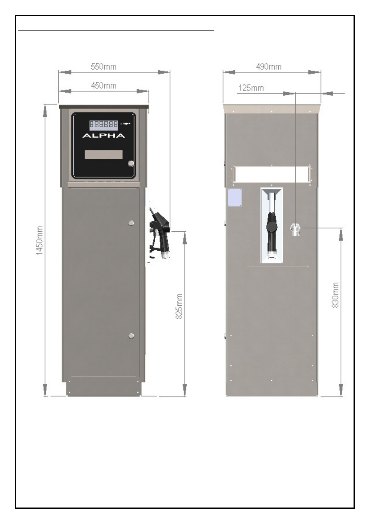
ALPHA EXTERNAL DIMENSIONS
S855/2
Page 12
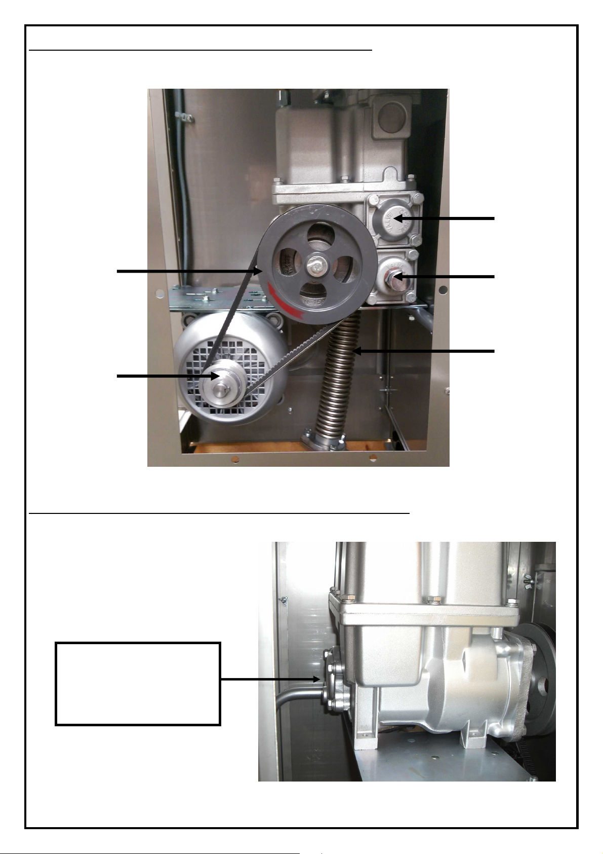
ALPHA SIDE ACCESS PANEL VIEW
THE FRONT
33
20 34
25
21
ALPHA PUMP UNIT FILTER LOCATION
FILTER LOCATION
AS VIEWED FROM
PUMP UNIT
S855/2
Page 13

ELECTRONIC DISPLAY/CALCULATOR
FEATURES
6-digit backlit Main LCD display: Up to 9999.99 or 99999.9 litres
per delivery
8-digit backlit totaliser LCD display: Up to 99999999 litres
Display retained during power failure
OPERATION
Stand-by mode: Upper line of LCD display shows previous delivery
Lower line of LCD display shows ongoing total
Nozzle removed: Upper line shows “all eights” then “all zeros”
Lower line shows “FUELLING”
Pump starts
Fuel drawn: Upper line shows litres dispensed
Lower line shows “FUELLING”
Nozzle Returned: Pump stops
Upper line of LCD display shows previous delivery
Lower line of LCD display shows ongoing total
S855/2
Page 14
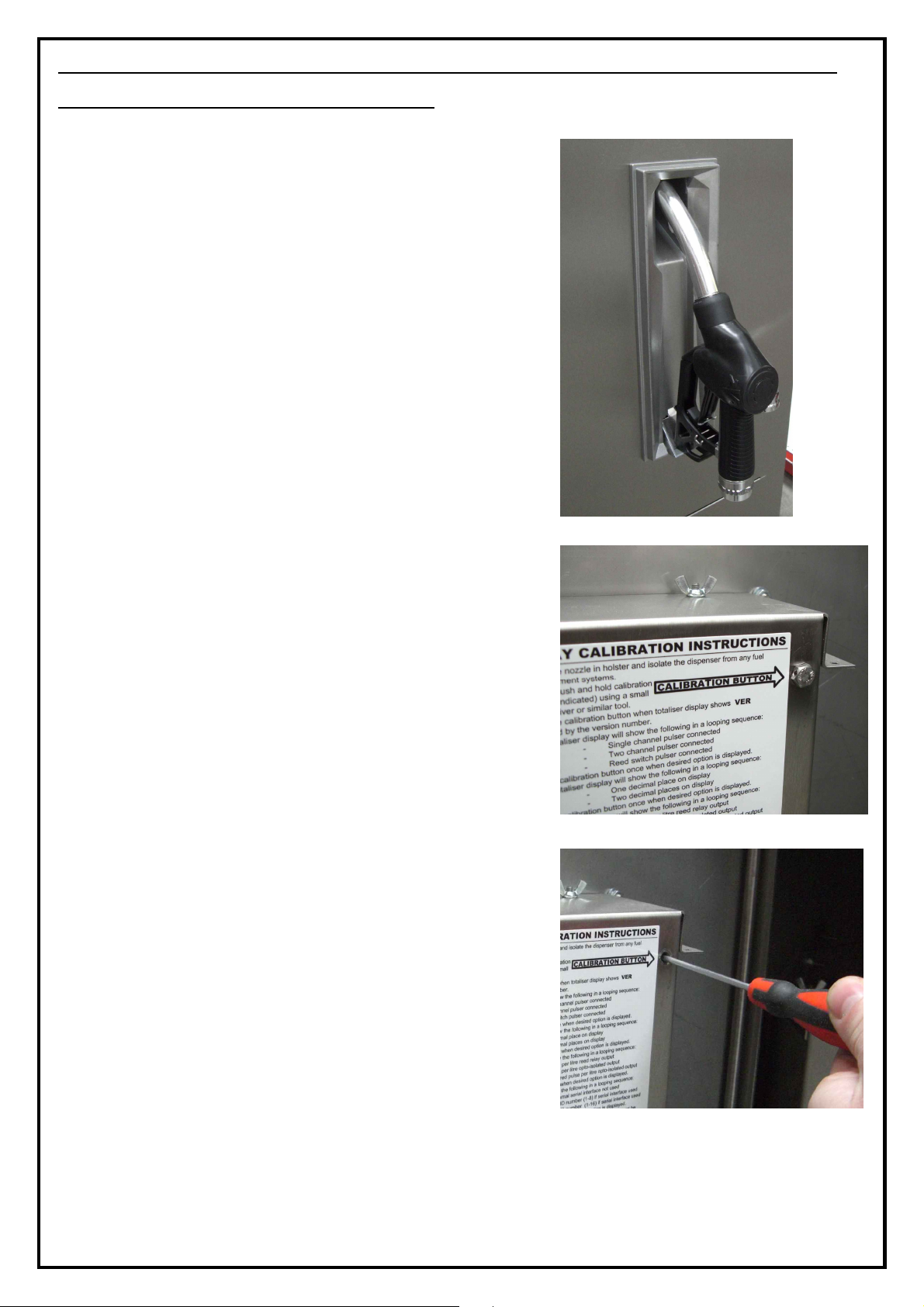
CALIBRATION PROCEDURE - (MUST BE CARRIED OUT TO
ENSURE PUMP ACCURACY)
1. Ensure the nozzle is stowed in the holster
and the dispenser is isolated from any
fuel management systems.
2. Remove calibration button cover bolt from
rear of display / calculator housing (if
fitted).
3. Gently push and hold the calibration
button using a small screwdriver or
similar tool.
S855/2
Page 15
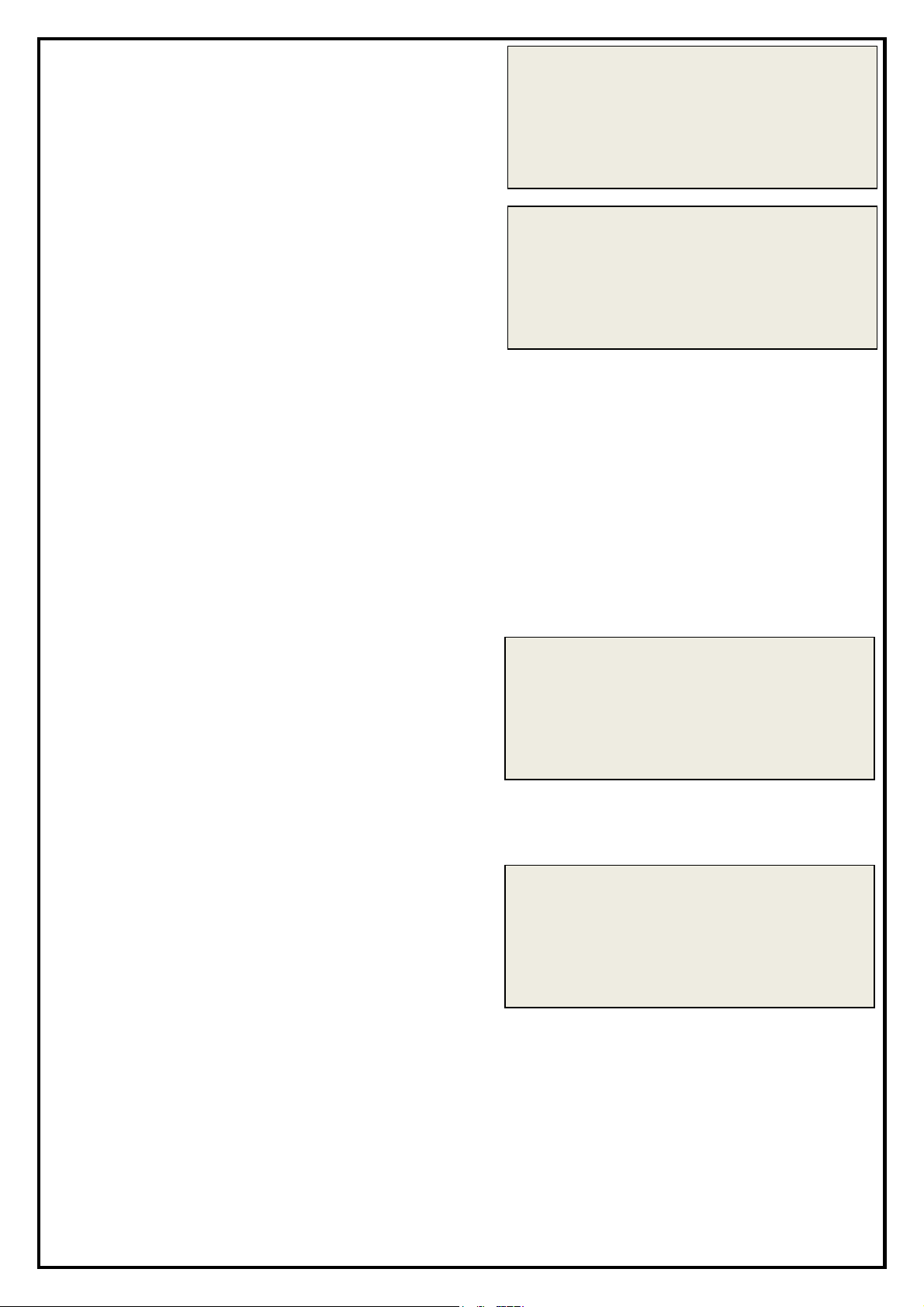
4.
00000.0
CALIB
VER 4.00
CALIB
CALIB
LITRES
CALIB
BACKLIGHT ON
Release the calibration button when
the totaliser display shows VER
followed by the version number on
the lower line of the display.
5. The lower line will show the following
in a looping sequence:
1 PULSE CHANNEL - Single
channel pulser connected
2 PULSE CHANNEL - Two channel
pulser connected
REED PULSER - Reed switch pulser
connected
Press calibration button once when desired option is displayed.
Select 2 PULSE CHANNEL for Weights & Measures Alpha, REED
PULSER for Alpha fitted with PULS.E18 reed switch pulser (pre
August 2003) or Adblue Alpha and 1 PULSE CHANNEL for all other
Alpha versions.
00000.0
1 PULSE CHANNEL
6. The lower line will show the following
in a looping sequence:
LITRES – Display measures in litres.
GALLONS – Display measures in
gallons (Imperial or US)
Press calibration button once when
desired option is displayed.
7. The lower line will show the following
in a looping sequence:
BACKLIGHT ON – backlight on
constantly.
BACKLIGHT OFF – backlight off.
ON FOR FUELLING – backlight only
on during fuelling.
00000.0
00000.0
Press calibration button once when
desired option is displayed.
S855/2
Page 16
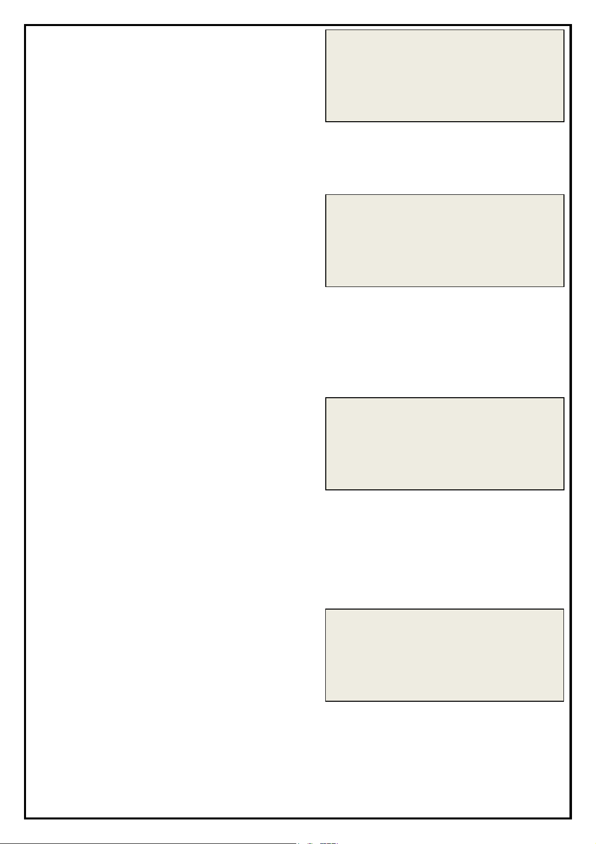
8. The lower line will show the following
0
0000.0
CALIB
CALIB
CALIB
00000.0
CALIB
in a looping sequence:
1 DECIMAL PLACE - One decimal
place on display
2 DECIMAL PLACE - Two decimal
places on display
Press calibration button once when
desired option is displayed.
9. The lower line will show the following
in a looping sequence:
1 DECIMAL PLACE
REED RELAY 10 - Ten pulse per
00000.0
litre reed relay output.
OPTO OUTPUT 10 - Ten pulse per
litre opto-isolated output.
OPTO OUTPUT 100 - One hundred
pulse per litre opto-isolated output.
Press calibration button once when
desired option is displayed.
10. The lower line will show the following
in a looping sequence:
TANK SW UNUSED – No “tank
00000.0
empty” switch connected.
TANK SW IS TA.F – “Tank empty”
switch connected is Hytek TA.F type*
(*Feature coming soon)
OPTO OUTPUT 10
TANK SW IS TA.F
TANK SW NOT TA.F – “Tank
empty” switch connected is standard
“normally closed” float switch*
(*Feature coming soon)
11. The lower line will show the following
in a looping sequence:
LEAK SW UNUSED – No “pump
leak” switch connected.
LEAK SW IS TA.F – “pump leak”
switch connected is Hytek TA.F type*
(*Feature coming soon)
LEAK SW NOT TA.F – “pump leak”
switch connected is standard
“normally open” float switch*
(*Feature coming soon)
LEAK SW IS TA.F
S855/2
Page 17
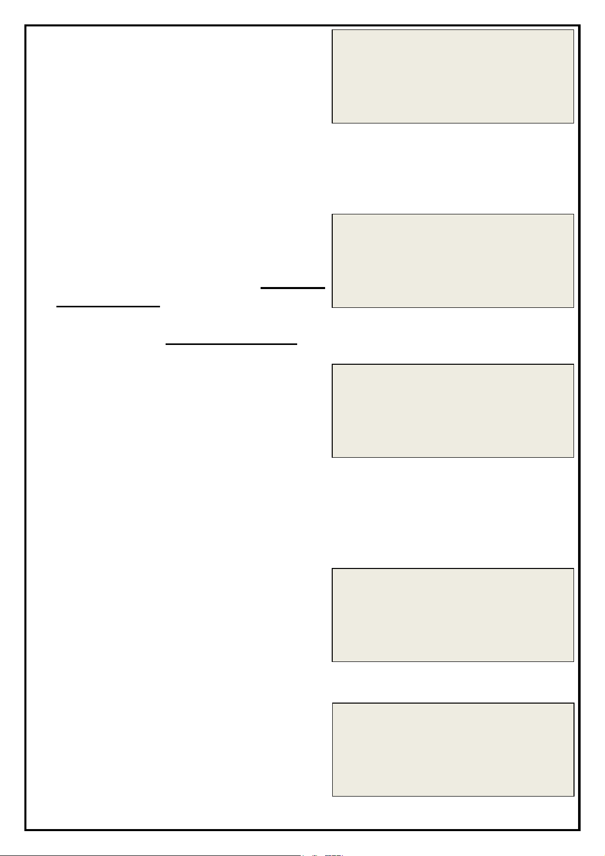
12. The lower line will show the following
CALIB
CALIB
CALIB
CALIBRATE PUMP
CALIB
DISPENSE 20L
CALIB
CALIBRATION OK
In a looping sequence:
NOZ 2 SW UNUSED – No additional
/remote nozzle switch connected.
2nd NOZ SW N/O– Additional nozzle
switch is normally open type.
2nd NOZ SW N/C – Additional
nozzle switch is normally closed
type.
13. The lower line will show the following
in a looping sequence:
STAND ALONE - Pump external
serial interface not used. SELECT
THIS OPTION
CONFIG NETWORK – Configure
serial network. DO NOT SELECT
00000.0
NOZ 2 SW UNUSED
00000.0
STAND ALONE
14. The lower line will show the following
in a looping sequence:
SAVE AND EXIT – Save all settings
entered and return to normal
operation.
CALIBRATE PUMP – Continue and
calibrate pump with 20 litre measure.
ABANDON CONFIG – Do not save
any settings entered and return to
normal operation.
15. If CALIBRATE PUMP was selected
TAKE NOZZLE will be shown.
Take the nozzle (the lower line will
show DISPENSE 20L) and dispense
20 litres into a calibrated test
00000.0
00000.0
measure.
16. Once 20 litres have been dispensed
hang up the nozzle. The lower line
should show CALIBRATION OK. If
there is an error in the calibration the
relevant error message will be
displayed.
00000.0
S855/2
Page 18

ERRORS
If an error occurs ERROR, followed by a brief description is shown on the
lower display. The errors are classified as follows:
FLOW TOO FAST The pulser has run too fast (in excess of 300 pulses
per second)
UNAUTH FLOW The meter has turned without the nozzle being
removed
CALIBRATE FAIL A time delay of 2 minutes or more has occurred
during the 20 litre calibration.
PULSER SIGNAL One of the pulse transmitter’s pulse trains has been
interrupted.
PULSE REVERSE The meter has run backwards during a delivery
PULSER POWER The pulser has been disconnected
The error condition is maintained until the nozzle is returned to its holster,
for at least 2 seconds, and then removed again to restart the fuelling
sequence.
TIMEOUT
If, during a delivery, no fuel is dispensed for 2 minutes the display will
show TIMEOUT alternating with REPLACE NOZZLE and the pump will
stop running until the nozzle is returned to its holster, for at least 2
seconds, and then removed again to restart the fuelling sequence.
S855/2
Page 19
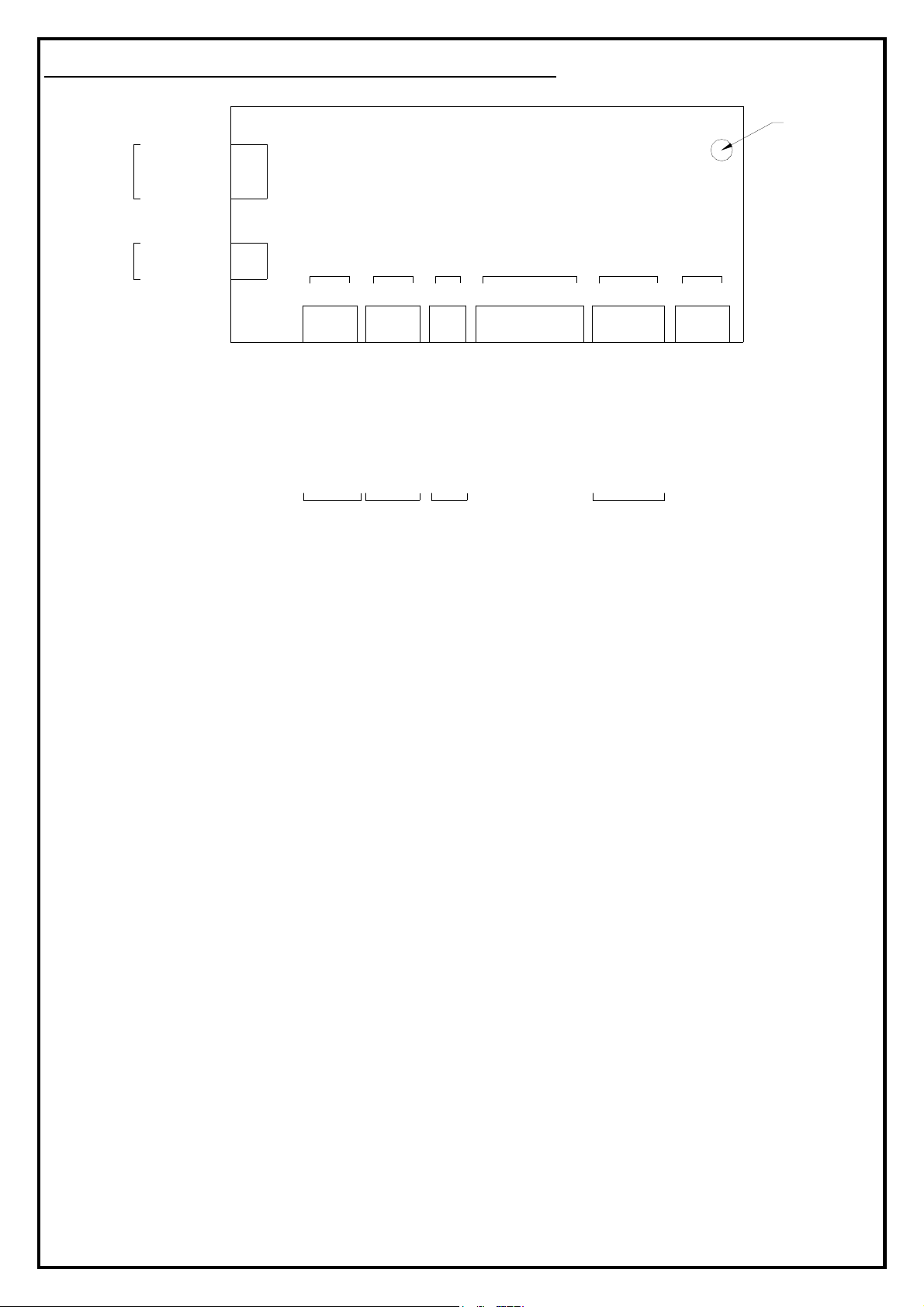
DISPLAY CONNECTION DIAGRAM
220/240 VAC
POWER
INPUT
220/240 VAC
MOTOR RELAY
OUTPUT
NEUTRAL
EARTH
LIVE
NEUTRAL - GREY
LIVE - BLACK
CALIBRATION
1 1 232
AC INPUT
PUMP
NOZZLE
GND
YELLOW
NOZZLE
SWITCH
INPUT
IN 12V
GREEN/BLUE
REED OPT
COM GND
21 3 21 21 321 3421 3
RED
COMMON - BROWN
REED RELAY - BLUE
OPTO ISOLATED - GRN/YEL
10:1 /
100:1
PULSE
OUTPUT
DISPLAY /
CALCULATOR
VIEWED FROM
REAR
SOLENOIDP/OUT
12V
12V DC SOL.
OUTPUT
(WEIGHTS &
MEASURES
VERSION
TANK LEAK EXT
GND SW GND SW GND SW
0V - BLUE
+12VDC - BROWN
ONLY)
SWITCHES
5 6 421 3
PULSE IN
+12VDCCH1 CH2 GND
+12VDC - RED (W&M GREEN)
CH 1 - YELLOW (W&M WHITE)
CH 2 - GREEN (W&M YELLOW)
PULSE
TRANSMITTER
INPUT
COMMS
+ -
GND
AND SCRN
0V - BLACK (W&M BROWN)
BUTTON
S855/2
Page 20
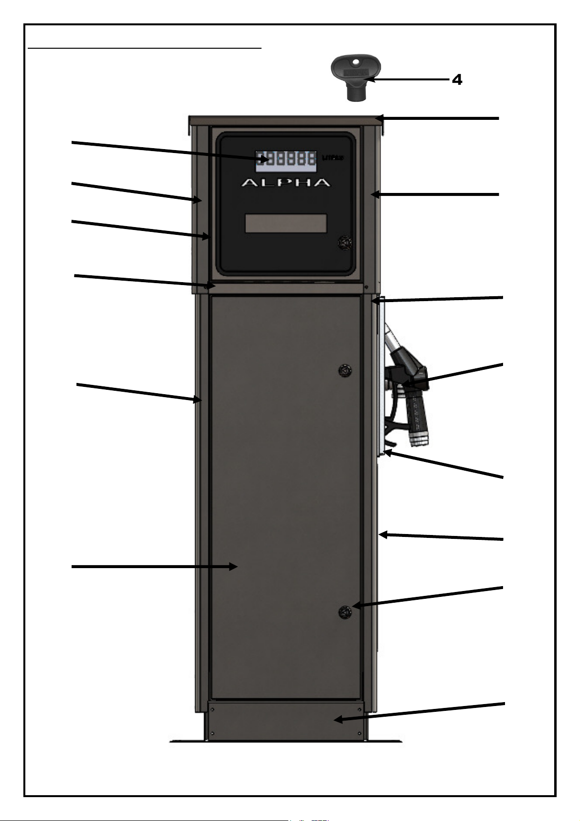
ALPHA EXTERNAL VIEW
1
2
3
11
5
7
8
6
12
13
14
2
10
9
S855/2
Page 21
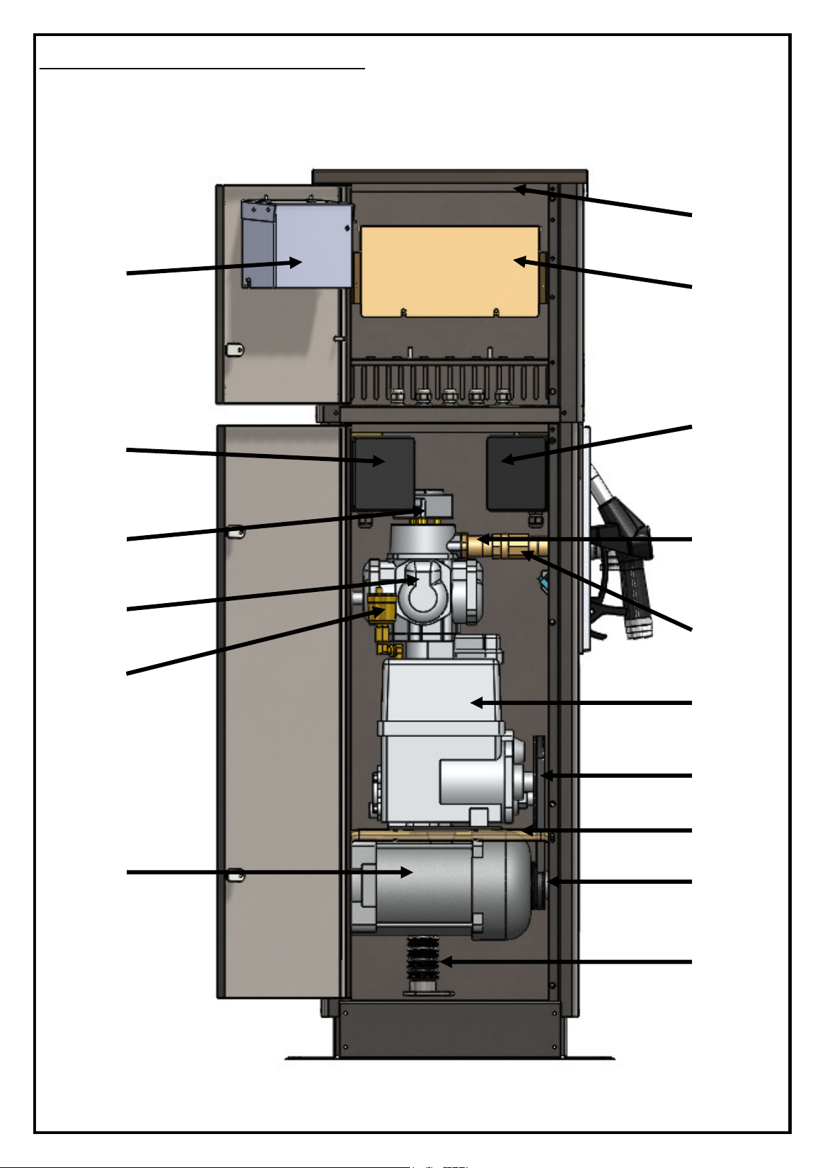
ALPHA INTERNAL VIEW
15
17
18
19
20
21
22
24
25
26
27
16
28
16
29
23
S855/2
Page 22

ALPHA PARTS LIST
DRG.
PART DESCRIPTION
PART NO.
PART NO.
EXTERNAL COMPONENTS
INTERNAL COMPONENTS
REF
1 LCD DISPLAY UNIT ALP.DISP.PCB.3A ALP.DISP.PCB.3A
(Above item includes LCD,
transformer board and fitting kit)
2 SIDE PANEL (UPPER CABINET) ALP.SPAN.E4 ALP.SPAN.E4
3 UPPER DOOR ALP.DOOR.E4 ALP.DOOR.E4
4 DOOR KEY 209.KEY 209.KEY
5 LOWER CABINET CAP ALP.CAP.H4 ALP.CAP.H4
6 SIDE PANEL (LOWER CABINET) ALP.SPAN.BL4 ALP.SPAN.BL4
7 LOWER DOOR ALP.DOORH4 ALP.DOORH4
LOWER DOOR (FRONT NOZZLE
OPTION)*
8 MOUNTING BASE ALP.BASE3 ALP.BASE3
9 LOCK (x 3) ALP.LOCK3 ALP.LOCK3
10 SIDE ACCESS PANEL ALP.ACCPAN3 ALP.ACCPAN3
11 NOZZLE HOLSTER WITH SWITCH ALP.NOZBOOT.P ALP.NOZBOOT.P
12 OUTLET ELBOW ELB.4FFCR ELB.4FFCR
13 SIDE PANEL WITH HOSE OUTLET ALP.SPAN.H4 ALP.SPAN.H4
SIDE PANEL WITH HOSE OUTLET
(FRONT NOZZLE OPTION)
14 TOP CAP ALP.CAP4 ALP.CAP4
15 DISPLAY COVER ALP.DISPCOV3A ALP.DISPCOV3A
16 MAINS/230VAC JUNCTION BOX ALP.JBOX.P ALP.JBOX.P
17 PULSER PULS.W PULS.W
18 4 PISTON METER (2 REV PER L) 209A.METER.REP 209A.METER.REP
19
20 MOTOR MOT.E75.ATEX MOT.E75.ATEX
21 FLEXIBLE SUCTION CONNECTOR TTLB TTLB
22 PULLEY PULL.2C PULL.25C
23 PUMP MOUNTING FRAME (x 2) ALP.PFRAME3 ALP.PFRAME3
24 PULLEY BELT VBLT.275 VBLT.28
25 PUMP UNIT (COMPLETE) 209A.PASSY.P 209A.PASSY.P
26 OUTLET CHECK VALVE CHK.1P.DRILL CHK.1P.DRILL
27 METER OUTLET PIPE ALP.OUTPIPE.W ALP.OUTPIPE.W
28 JUNCTION BOX ALP.DBOX3 ALP.DBOX3
29 UPPER PANEL (x 2) ALP.UPAN4 ALP.UPAN4
30 INLET FLANGE* FLNG FLNG
31 INLET GASKET* GSK.TRI.P GSK.TRI.P
32 RELAY (INSIDE JUNCTION BOX)* ALP.RELAY ALP.RELAY
33 PUMP MOUNTING PLATE* ALP.PPLATE3C ALP.PPLATE3C
34 CHECK VALVE* 209EP.21 209EP.21
35 BYPASS VALVE* 209EP.29 209EP.29
36 PUMP UNIT VANES* (X 6) 209EP.38 209EP.38
37 PUMP UNIT FILTER* 209EP.3 209EP.3
AIR SEPARATOR OUTLET FLOAT
CHAMBER
*Not shown on illustration
ALP.DOORHF4 ALP.DOORHF4
ALP.SPAN.HF4 ALP.SPAN.HF4
MINIVENT MINIVENT
P50
P70
S855/2
Page 23

S855/2
Page 24

E.U. DECLARATION OF CONFORMITY
Company Name: Hytek (GB) Ltd
Address: Delta House, Green Street. Elsenham,
Bishops Stortford, Hertfordshire, CM22 6DS, UK
Date of Issue: 25
Equipment Details: Alpha ATEX Fuel Pumps with Fuel Control
Applicable Directives: 2004/108/EC EMC Directive &
& Standards 2014/30/EU EMC Directive (effective date 20th April 2016)
EN 61000-6-3:2007 (+A1)
EN 61000-6-2:2005
2006/42/EC Machinery Directive
2012/19/EU Waste Electrical & Electronic Equipment Regulations
2011/65/EU Restriction of Hazardous Substances Directive (RoHS2)
EN 13617-1:2012 & EN 1127-1:2011
Marking: Ex II 2 G
Declaration Number: EU137/1
On behalf of the above named company, I declare under our sole responsibility that, on the date the
equipment accompanied by this declaration is placed on the market, the equipment conforms with
all technical and regulatory requirements of the above listed directives.
THE INFORMATION CONTAINED IN THIS DOCUMENT IS PROTECTED BY COPYRIGHT © AND PROPERTY
LAWS AND IS THE SOLE PROPERTY OF HYTEK (GB) LTD. ANY REPRODUCTION IN PART OR AS A WHOLE
WITHOUT THE WRITTEN PERMISSION OF HYTEK (GB) LTD IS PROHIBITED.
th
July 2017
ALPHA/50P, ALPHA/50LP, ALPHA/50FP, ALPHA/70P, ALPHA/70LP,
ALPHA/70FP
Electromagnetic compatibility (EMC) - Part 6-3: Generic standards Emission std. for residential, commercial & light-industrial environments
Electromagnetic compatibility (EMC) Part 6-2: Generic standards Immunity for industrial environments
2014/35/EU Low Voltage Directive
2014/68/EU Pressure Equipment Directive
2014/34/EU ATEX Directive
EC Type examination Certificate No.: CML 17ATEX9254
EN 13617-1:2012
Ta= -20°C to + 40°C
Notified Body: CML Ltd. Number 2503
Unit 1 Newport Business Park, New Port Road
Ellesmere Port, CH65 4LZ UK
Clive Wellings, Technical Manager
S855/2
 Loading...