

HY Technologies F2R4L, F4R4L, F4R4B, F2R4B User Manual

User’s Manual
Front and Rear Parking Sensor System
2 or 4 Front and 4 Rear In-Bumper Sensors
With Wired LED Display and Built-in Beeper
2 or 4 Front and 4 Rear In-Bumper Sensors
For Cars, Mini-VANs, 4X4s, SUVs, and Small Trucks
Note for 6-Sensor Parking System
If you purchased a 6-sensor system (F2R4B or F2R4L), it is
actually our 8-sensor system shipped with two(2) front sensors.
The two front sensors shipped with the 6-sensor system are
labeled as ‘E’ and ‘H’. Depending on your specific vehicle or
application, they can be plugged into either the control box’s
ports ‘E’ and ‘H’ or ports ‘F’ and ‘G’ corresponding to the same
sensor locations on the front bumper of vehicle as shown in
Fig. 2 in the User's Manual.
Install the two front sensors to bumper locations ‘E’ and ‘H’ for
better corner coverage of the front bumper, or install to bumper
locations ‘F’ and ‘G’ for a balanced front bumper coverage as
shown in Fig.2 in the User's Manual.
Two additional front sensors can be ordered at our online store
and added to the 6-sensor system to make it a 8-sensor
system as the control box is 8-sensor ready.
(LED System, F2R4L, F4R4L)
With Beeper Only
(Beeper Only System, F2R4B, F4R4B)
ISO9001
All Rights Reserved HY Technologies Milpitas California USA http://parkingsensors.net

Front and Rear Parking Sensor System
Included in the Box *
● 6 or 8x Sensors (in-bumper type) with
attached cable and 2-pin mini connector.
Cable Length: Front Sensor = 26.2ft
(8.0m); Rear Sensor = 8.2ft (2.5m)
● 1x LED Display with built-in beeper,
On/Off switch, and 8-pin plug with
19.7ft/6m attached cable – for LED
System (F2R4L, F4R4L)
● 1x Beeper with 8.2ft/2.5m attached cable
– for Beeper Only System (F2R4B,
F4R4B)
Features *
● Front and Rear Parking Sensor System to
provide good coverage of both front and
rear end of vehicle
● 2 or 4 front and 4 rear in-bumper sensors
to give the look of factory installed system
● Rear sensors are activated while reversing
and front sensors are activated while
forward-parking with foot-braking
● Beeping faster when getting closer to
obstacle
● Designed for cars, SUVs, 4x4s,
Mini-VANs, and small trucks
● Limited 12 Month Warranty
Specifications *
● FCC CE ISO9001 Approved
● Operating Voltage: DC +10.5 ~ +16V
● Detecting Range: Front: 1.0 ~ 3.3 ft (0.3 ~
1.0m); Rear: 1.0 ~ 4.9 ft (0.3 ~ 1.5m).
● Measuring Error: ± 0.1 ft (or 0.1m)
● Sensor Detection Angle: 60°
● Sensor Diameter: 0.83 in/21mm
● Sensor Length: 0.71 in/18 mm.
● Detection Response Time: 300ms
● Audible Alert when obstacle within: 1.0 ~
3.3 ft (0.3 ~ 1.0m) in front; 1.0 ~ 4.9 ft (0.3
~ 1.5m) in rear.
● Ultrasonic Frequency: 40Khz
● Audible Alert Volume: 60 db
* For reference only and may be changed without prior notice.
● 1x Control Box
● 1x Double-Sided Self-Adhesive Pad for
affixing control box to vehicle
● 1x Power Cable for Control Box including
four wires (red, black, yellow and blue) with
4-pin connector. Length: 3.3ft/1.0m
● 1x Drill Bit (Hole Saw) - Φ21mm.
● 2 or 8x Plastic Sensor Spacers with
wedged thickness for non-vertical bumpers
● 1x User’s Manual in English
Beeper Only System (F2R4B, F4R4B)
● Audible alert (beeper) without display for
easy installation without cluttering the dash
LED System (F2R4L, F4R4L)
● Wired LED Display with Built-in Audible Alert
(Beeper) with On/Off Switch
● Seven (7) LED Lights on each side of the
display to indicate both orientation of
obstacles and Safe/Warning/Stop zone
● Distance display in feet or meters
● Maximum Power Consumption: 4W
● Current Consumption: 100~300mA
● Operating Temperature Range: -20 ~ +70°C
● Dimensions of the Control Box: WxDxH =
3.9" x 2.8" x 1.0" (10.0cm x 7.2cm x 2.5cm)
● LED System (F2R4L, F4R4L)
Dimensions of the LED Display: WxDxH =
5.2" x 1.2" x 1.1" (13.4cm x 3.0cm x 2.8cm)
● Beeper Only System (F2R4B, F4R4B)
Size of the Beeper: diameter = 1.6" (4.0cm);
thickness = 0.7" (1.7cm)
- 1 -
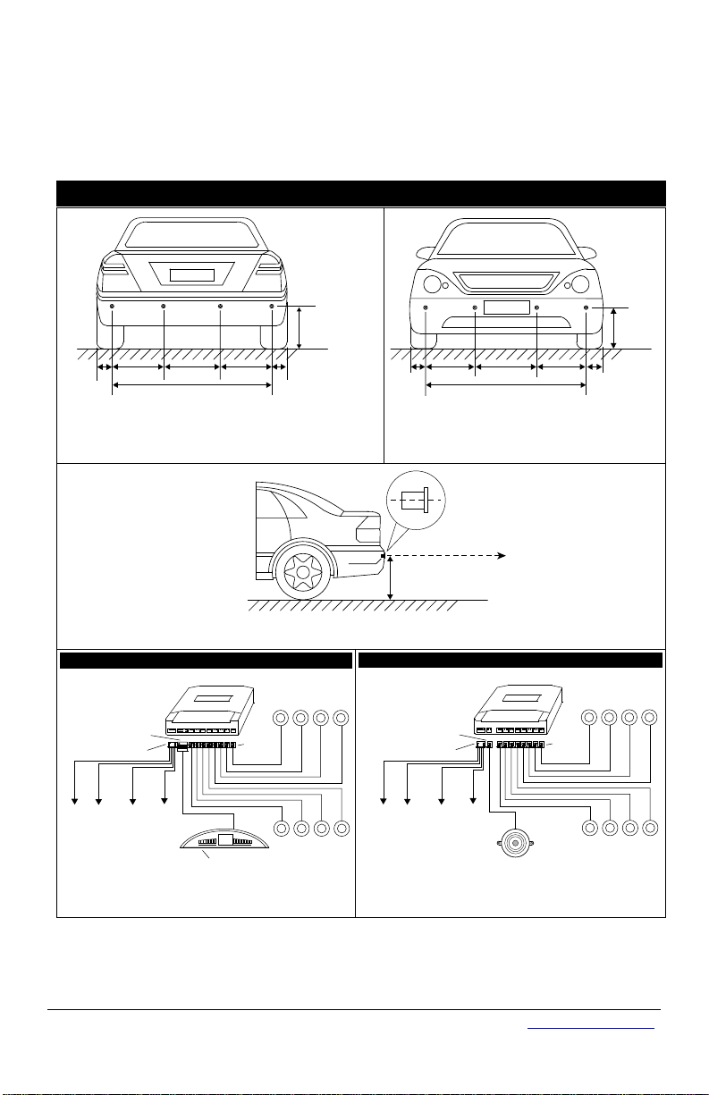
Fig. 4 Control Box, Display, Sensors, and Wiring
L2
H
L1 L3 L4
L1
Fig.1 Mounting Height and Position (Rear Sensors)
H = 50 ~ 80cm (20” ~ 32”)
L1 = 6 ~ 15cm (2” ~ 6”)
L2 = L3 = L4 or L2 = L4 = 0.3L, L3 = 0.4L
Ground
L
Ground
50 ~ 80cm (20” ~ 32”)
Sensor Center Line
Parallel to Ground
Sensor
Sensor Mounting Height
Fig.3 Mounting Height and Angle of Sensors
D
C
BA
L5 L8
L7 L6 L5
H
Fig. 2 Mounting Height and Position (Front Sensors)
H = 50 ~ 80cm (20” ~ 32”)
L5 = 6 ~ 15cm (2” ~ 6”)
L6 = L7 = L8 or L6 = L8 = 0.3L, L7 = 0.4L
Ground
L
E
F
GH
Control Box
A B
C D
PWR
Beeper On/Off Switch
on Back of Display
R
L
8.8
LED Display
Power Plug
Sensor
Plugs
EFG
H
DISP
D
C
B
A
Rear Sensors
EF
G
H
Front Sensors
Display Plug
Control Box
8-SENSOR SYSTEM - WIRING, SENSOR MOUNTING HEIGHT AND POSITION
Fig. 5 Control Box, Beeper, Sensors, and Wiring
To Reverse Light
(+) 12V
Red
To Ground (-)
Control Box
A B
C D
PWR
Power Plug
Sensor
Plugs
EFG
H
DISP
D
C
B
A
Rear Sensors
EF
G
H
Front Sensors
To Brake Light
(+) 12V
Yellow
Black
Beeper Plug
Control Box
Beeper
To Igniton or ACC
(+) 12V
Blue
To Reverse Light
(+) 12V
Red
To Ground (-)
To Brake Light
(+) 12V
Yellow
Black
To Igniton or ACC
(+) 12V
Blue
LED DISPLAY SYSTEM (F2R4L, F4R4L)
BEEPER ONLY SYSTEM (F2R4B, F4R4B)
All Rights Reserved HY Technologies Milpitas California USA http://parkingsensors.net
- 2 -

How the System Works
The Parking Sensor System determines obstacle distance by measuring the time needed for the
ultrasonic wave emitted by a sensor to reach an obstacle and for the sensor to receive the
ultrasonic wave reflected from the obstacle. Given the speed of the ultrasonic wave, the system
can then calculate and display the distance between the sensor and the obstacle.
To provide good coverage for both front and rear end of vehicle, the system comes with 6 or 8
sensors (2 or 4 front and 4 rear sensors). ♦ To have the look of factory installed system, the 6 or
8 sensors are in-bumper type (to be installed in the front and rear bumpers by drilling holes
through the bumpers). ♦ Controlled by +12V from the back up light, the rear sensors are
activated when the vehicle is put in reverse. ♦ Controlled by +12V from the brake light, the front
sensors are activated when parking/driving forward with foot-braking. ♦ For LED System (F2R4L,
F4R4L), it comes with a wired LED display which shows the distance of an obstacle in front or
rear of the vehicle (displayed as 0.0 if obstacle is within 1 ft or 0.3m). Seven (7) LED Lights
(Green/Yellow/Red) on each side of the distance display indicate both orientation of obstacles
and Safe/Warning/Stop zone. The audible alert (beeper) is built in the display with On/Off switch.
♦ For Beeper Only System (F2R4B ,F4R4B), it comes with a beeper (audible alert) only for easy
installation without cluttering the dash. ♦ The system beeps faster as vehicle gets closer to an
obstacle and sounds continuously when vehicle is within 1 ft or 0.3m from an obstacle.
Note: the front sensors may continue to work for 20 more seconds after foot brake is released.
Tools Needed
Φ21mm drill bit (include), drill, tape measure, chalk or marker, wire stripper, vinyl electrical tape,
cable/wire ties, voltage meter, screw driver set, pliers.
Note: Use a bi-metal 22mm drill bit (not included) if drilling through metal bumpers. For metal
bumpers, holes drilled need to be slightly larger than diameter of sensors.
Installation and Wiring
IMPORTANT: (a) Read this manual thoroughly before proceeding to installation. You can also
have the system installed by a professional installer such as your local auto mechanic/auto
electrician/car stereo store. (b) Turn off the engine and ACC during installation. (c) Double
check that all wiring is correct before powering on the system. (d) During installation, avoid
flatting, perforating, cutting, and extending the wires of sensors to reduce unnecessary signal
loss. (e) Never pull the sensor cables too hard or sensors may not work properly or at all.
1. Installing the Control Box
a) Find a flat and clean surface for the control box inside the vehicle near driver's side taillight
assembly but away from it for least 1 ft. As the control box is not water-proof type, you need
to mount the control box to a location that is protected from water. Keep it away from areas
of high heat, high humidity, direct sunlight, and electromagnetic devices.
b) Place the control box in place temporarily without securing it to the vehicle as you may need
to adjust the location of the control box while wiring. Note: After the system is working
properly, use the double-sided self-adhesive pad (included) to secure it to the vehicle.
c) Insert the 4-pin plug of the power cable for the control box into its 4-pin socket labeled
"PWR" on the front side of the control box. See Fig. 4 (LED System) or Fig.5 (Beeper Only
System).
Important Notes for Installing the Control Box:
Don't mount the control box near or under the dash or in the cab of a truck.
The control box is designed to be mounted near the rear end of a vehicle (near taillight
assembly) to avoid interferences from the engine which may cause false alert such as
continuous beeping and 0.0 display (LED System only).
If Installing the System to a Truck, as the control box is not water-proof type, you may need to
first mount the control box in a small water-proof metal or plastic box (not included with the
system), then fix it to a location near the rear end of the truck.
- 3 -
 Loading...