

Page 1

- 11 -
The specifications and features of the system, Terms & Conditions, Return Policy, and Warranty
included in this User's Manual may be changed or updated at any time for any reasons without
prior notice.
HY Technologies ● http://parkingsensors.net
Copyright © 2009 HY Technologies ● Milpitas ● California ● USA All Rights Reserved
Made In China
User’s Manual
Front and Rear Parking Sensor System
4 Front and 4 Rear In-Bumper Sensors
With Beeper Only
Model F4R4BX
For Cars, Mini-VANs, 4X4s, SUVs, and Small Trucks
(Vehicle Length Under 17 Feet)
ISO9001
HY Technologies ● http://parkingsensors.net
Copyright © 2009 HY Technologies ● Milpitas ● California ● USA All Rights Reserved
Page 2

- 1 -
Front and Rear Parking Sensor System
4 Front and 4 Rear In-Bumper Sensors
With Beeper Only
For Cars, Mini-VANs, 4X4s, SUVs, and Small Trucks
(Vehicle Length Under 17 Feet)
Included in the Box
● 8x Sensors (in-bumper type) with
attached cable and 2-pin mini plug. Cable
Length: Front Sensor = 6.0m (19.6ft); Rear
Sensor = 2.5m (8.2ft)
● 1x Beeper with attached cable (yellow,
red-white). Length: 2.5m (8.2ft).
Double-sided self-adhesive pad on bottom
of the beeper.
● 1x Control Box
● 1x Double-Sided Self-Adhesive Pad with
Velcro Attachment for affixing control box
to vehicle
● 1x Power Cable for Control Box with five
wires (black, yellow, blue, white, and red)
with a 5-pin connector on one end. Length:
2.5m (8.2ft). Note: the red wire for ACC is
7m (23ft) with 5A fuse near the 5-pin plug
● 1x Drill Bit (Hole Saw) - Φ22.3 mm (7/8”)
● 1x User’s Manual
Features
● Front and Rear Parking Sensor System to
provide good coverage of both front and
rear end of vehicle
● 4 front and 4 rear in-bumper sensors to
give the look of factory installed system
● Rear sensors activated while reversing and
front sensors activated while forward
parking with braking
● Wedged sensor edge to adjust for
non-vertical bumpers
● Audible alert (beeper) without display
meaning easy to install and neat dash
● Beeping faster when getting closer to
obstacle
● Designed for cars, SUVs, 4x4s, Mini-VANs,
and small trucks (vehicle length under 17’)
● Limited 12 Month Warranty
Specifications (for reference only and may be changed without prior notice)
● FCC CE ISO9001 Approved
● Operating Voltage: DC +10.5 ~ +16V
● Detecting Range
Front Sensors:
E,H: 0.8m (2.6t); F,G: 1.2m (3.9ft)
Rear Sensors:
A,D: 1.0m (3.3ft); B,C: 2.0m (6.6ft)
● Sensor Detection Angle: 90°
● Sensor Diameter: Φ22mm (0.87”)
● Sensor Length: 21mm (0.83”)
● Detection Response Time: 300ms
● Ultrasonic Frequency: 40Khz
● Audible Alert Volume: 60 db
● Maximum Power Consumption: 4W
● Current Consumption: 100~300mA
● Operating Temperature Range: -30 ~ +70°C
● Dimensions of the Control Box: WxDxH =
11.0cm x 8.0cm x 3.0cm (4.3" x 3.1" x 1.2")
● Size of the Beeper: diameter = 3.0cm(1.2”);
thickness = 1.5cm(0.6")
HY Technologies ● http://parkingsensors.net
Copyright © 2009 HY Technologies ● Milpitas ● California ● USA All Rights Reserved
- 10 -
Customer Service and Technical Support
For customer service and technical support, visit our Web site as listed below, then click on the
link Contact Us
.
Spare and Replacement Parts
To order spare and replacement parts for your system, visit our Web site as listed below, then
click on the link Replacement Parts
.
HY Technologies ● http://parkingsensors.net
Copyright © 2009 HY Technologies ● Milpitas ● California ● USA All Rights Re served
Page 3
- 9 -
the customer. It is the customer's responsibility to make all arrangements with us for refused
shipments.
You are responsible for the shipping and handling cost to mail the defective parts, returns,
exchanges, and items for Warranty back to us and for us to ship them to you.
You are responsible for the customs duty, tariff or import tax charged by the customs in your
country.
HY Technologies ● http://parkingsensors.net
Copyright © 2009 HY Technologies ● Milpitas ● California ● USA All Rights Reserved
- 2 -
HY Technologies ● http://parkingsensors.net
Copyright © 2009 HY Technologies ● Milpitas ● California ● USA All Rights Re served
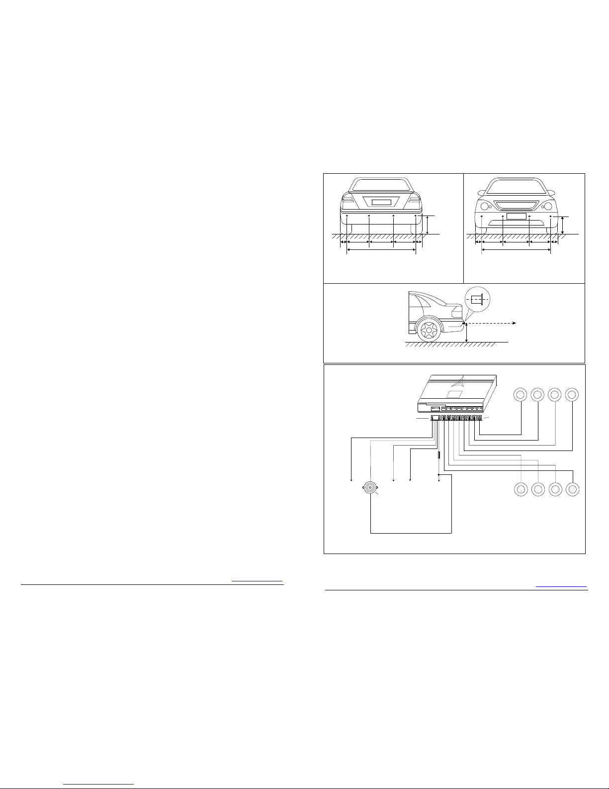
Fig. 4 Control Box, Beeper, Sensors, and Wiring
Control Box
H G F E
PWR
Power Plug
Sensor
Plugs
D C B A
DISP
H
G
F
E
Front Sensors
DC
B
A
Rear Sensors
To ACC +12V
Red
To Brake Light +12V
To Back Up Light +12V
White
Yellow
Blue
Black
To Chassis or Gnd (-)
Beeper
Red-White
Fuse(5A)
L2
H
L1 L3 L4
L1
Fig.1 Mounting Height and Position (Rear Sensors)
H = 50 ~ 80cm (20” ~ 32”)
L1 = 6 ~ 15cm (2” ~ 6”)
L2 = L3 = L4 or L2 = L4 = 0.3L, L3 = 0.4L
Ground
L
Ground
50 ~ 80cm (20” ~ 32”)
Sensor Center Line
Parallel to Ground
Sensor
Sensor Mounting Height
Fig.3 Mounting Height and Angle of Sensors
A
B
CD
L5 L8
L7 L6 L5
H
Fig. 2 Mounting Height and Position (Front Sensors)
H = 50 ~ 80cm (20” ~ 32”)
L5 = 6 ~ 15cm (2” ~ 6”)
L6 = L7 = L8 or L6 = L8 = 0.3L, L7 = 0.4L
Ground
L
H
G
FE
Page 4

- 3 -
How the System Works
The Parking Sensor System determines obstacle distance by measuring the time needed for
the ultrasonic wave emitted by a sensor to reach an obstacle and for the sensor to receive the
ultrasonic wave reflected from the obstacle. Given the speed of the ultrasonic wave, the system
can then calculate and display the distance between the sensor and the obstacle.
To provide good coverage for both front and rear end of vehicle, the system comes with 8
sensors (4 front and 4 rear sensors). ♦ To have the look of factory installed system, the 8
sensors are in-bumper type (to be installed in the front and rear bumpers by drilling holes
through the bumpers). ♦ Controlled by +12V from the back up light, the rear sensors are
activated when the vehicle is put in reverse. ♦ Controlled by +12V from the brake light, the front
sensors are activated when forward parking/driving with braking. ♦ It comes with a beeper
(audible alert) which beeps faster as vehicle gets closer to obstacle and sounds continuously
when vehicle is within 0.4m (1.3ft) from an obstacle.
Note:
♦ The front sensors will continue to work for 10 more seconds after brake is released.
♦ The system may beep once under the following conditions to let the driver know the system is activated and ready or
deactivated: (1) When vehicle is started or ACC is turned on or off (2) When vehicle is put in Reverse gear.
Tools Needed
Φ22.3mm (7/8") drill bit (include), drill, tape measure, chalk or marker, wire stripper, vinyl
electrical tape, cable/wire ties, voltage meter or test light, screw driver set, pliers.
Note: Use a bi-metal 22.3mm (7/8") drill bit (not included) if drilling through metal bumpers.
Installation and Wiring
IMPORTANT: (a) Read this manual thoroughly before proceeding to installation. You can also
have the system installed by a professional installer such as your local auto mechanic/auto
electrician/car stereo store. (b) Turn off the engine and ACC during installation. (c) Double
check that all wiring is correct before powering on the system. (d) During installation, avoid
flatting, perforating, cutting, and extending the wires of sensors to reduce unnecessary signal
loss.
1. Installing the Control Box
a) Find a flat and clean surface for the control box inside the vehicle near the driver's side
taillight assembly. Note: To avoid possible interferences from the taillight assembly, keep
the control box away from the taillight assembly for
at least 12”. As the control box is not
w
ater-proof type, you need to mount the control box to a location that is protected from water.
Keep it away from areas of high heat, high humidity, direct sunlight, and electromagnetic
devices.
b) Place the control box in place temporarily without securing it to the vehicle as you may need
to adjust the location of the control box while wiring. Note: After completing all wiring, use
the double-sided self-adhesive pad (included) to secure it to the vehicle.
c) Insert the 5-pin plug of the power cable for the control box into its 5-pin socket labeled
"PWR" on the front side of the control box. See Fig. 4 for details.
Important Notes for Installing the Control Box:
Don't mount the control box near or under the dash or in the cab of a truck.
The control box is designed to be mounted near the rear end of a vehicle to avoid interferences from the engine which may
cause false alert such as continuous beeping.
If Installing the System to a Truck, as the control box is not water-proof type, you may need to first mount the control box in a
small water-proof metal or plastic box (not included with the system), then fix it to a location near the rear end of the truck.
Note: Some lights (turn signal/brake/reverse/stop lights) may emit interferences that can affect the signals the control box
receives therefore cause the system to give false alert. After installation, if you experience false alert caused by turn signal
light, or brake/reverse/stop lights, try to put the control box as far as possible away (at least 12 inches) from the taillight
assembly (turn signal/brake/reverse/stop lights).
- 8 -
Terms & Conditions, Return Policy, and Warranty
IMPORTANT: the parking sensor systems and parts sold and distributed by us are only devices
used to assist a driver while parking. They should not be considered as a substitute for driver
responsibility when operating a vehicle. No warranty as to operational efficiency is granted. We
don't guarantee or assume liability for collisions or damages that take place when parking your
vehicle with use of the parking sensor systems or parts. We will not be liable for any claims,
actions, suit proceedings, costs, expenses, damages or liabilities arising out of use of the
systems or parts. By placing an order for the parking sensor system(s) or parts, customer
agrees to take full responsibility of use of such system(s) or parts.
Returns/exchanges can only be accepted if they are within 15 days of your receipt of your order.
Before your return, you must e-mail our Customer Service to get your Return Merchandise
Authorization Number (RMA#) for your return to be processed.
We offer 12-month limited warranty on our products from date of purchase. After an item(s)
is/are returned to us, it/they will be checked and tested by our technical support. If the item(s)
is/are found as defective in materials and workmanship, and qualified for our warranty, they will
be either repaired or replaced for free (shipping cost excluded). If they are found as not qualified
for our warranty, then you need to pay for the repaired or replacement items at their full retail
prices (see below: Items with the following conditions are not qualified for our warranty).
The warranty excludes defects or damage due to misuse, abuse or neglect.
This warranty does not cover any cost incurred in inspection, installation and repair services
involved.
Items with the following conditions are not qualified for our warranty:
Customer can cut or extend wires or cables for more flexible installations, but please note that
items with wires or cables cut void the warranty on the items.
Customer can paint sensors to match his vehicle color, but please note that sensors painted by
customer void the warranty on the sensors.
Sensors with any type of glue or silicone applied void the warranty on the sensors.
Items with seal (if any) broken, case (if any) opened, repaired, modified, or disassembled by
customer void the warranty.
Items for return must be in new, uninstalled, unused, re-sellable condition, including the
original packaging, manufacturer's containers, documentation, warranty cards, manuals,
and all accessories.
Re-packing and Re-stocking fee:
Unopened returns are subject to a 15% re-stocking fee.
Opened returns are subject to a 25% re-packing and re-stocking fee.
Returns which are damaged or have parts missing (not caused by shipping process) may be
subject to a greater re-stocking fee, or charged at their full retail prices and deducted from
refund amount.
Shipping and Handling fee is not refundable.
Returns are not acceptable if the packaging is not in its original condition or the item has
been used or installed.
International orders are not returnable.
If a domestic or international shipment is refused by the customer or customs and returned back
to us, a 15% restocking fee will apply less the shipping cost and any other fees incurred if any to
Page 5
- 7 -
Warnings
● To avoid collision with obstacle because of the inertia of vehicle while backing up/parking,
keep your vehicle speed at about 3 miles per hour and stop the vehicle immediately once
you hear the continuous beeping. This is because even if you have applied brake, your
vehicle will still go for some distance (inertia) before it comes to a complete stop.
● Because the parking system detects obstacle by emitting ultrasonic wave and receiving
reflected ultrasonic wave from obstacle, the system may fail to give both visual and audible
alert if an obstacle has smooth ball-shaped or sloped surfaces as such surfaces may not
reflect ultrasonic wave back to the sensors. Drivers in these situations should pay more
attention while parking their vehicles.
● In falling rain or snow, the system may give alert as falling rain or snow may be detected as
obstacles. Keep surface of sensors clean of snow, mud, dirt, and other debris.
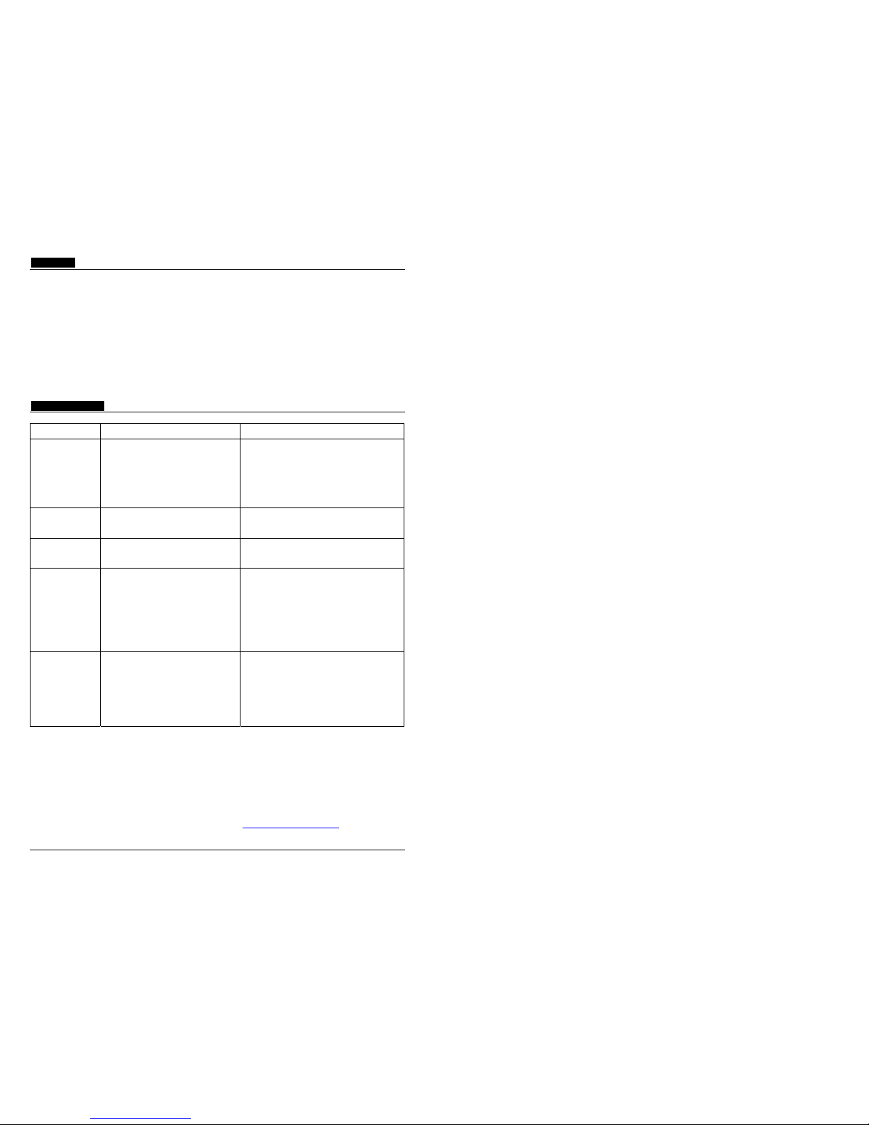
Troubleshooting
Problem Cause Solution
No beeping when
reversing or
forward parking
with braking
Or system is not
detecting any
obstacle in front
and rear
1. Red wire not connected to ACC.
2. Black wire not grounded properly.
3. Blue wire not connected to backup light.
4. White wire not connected to brake light.
5. Beeper not connected properly.
6. Faulty beeper.
7. Faulty control box.
1. Check if red wire gets +12V from ACC.
2. Check if black wire is grounded properly.
3. Check if blue wire gets +12V from backup light.
4. Check if white wire gets +12V from brake light.
5. Check beeper connection to control box.
6. Replace the beeper.
7. Replace the control box.
System is not
detecting any
obstacle in front
White wire not connected to brake light. Check if white wire gets +12V from brake light.
System is not
detecting any
obstacle in rear
Blue wire not connected to backup light. Check if blue wire gets +12V from backup light.
Beeps
continuously
1. Object within 0.3m is detected.
2. Faulty sensor(s).
3. Faulty control box.
4. Holes drilled for senso rs are too tight
(especially for a metal bumper).
1. Unplug all sensors, and then plug back in one
sensor at a time to find out which sensor is
causing the problem. Adjust angle of the sensor
so it points upward a few degrees above
horizontal line. Refer to 4. Installing the Sensors
for details.
2. Replace the sensor(s).
3. Replace the main control box.
4. Carefully enlarging sensor holes a little with a
small round file.
Beeps even there
is no obstacle
behind or in the
front
1. Ground is detected, or sensor angle is
low towards the ground, or sensors
installed too low (mounting height below
0.5m).
2. Holes drilled for senso rs are too tight
(especially for a metal bumper).
1. Unplug all sensors, and then plug back in one
sensor at a time to find out which sensor is
causing the problem. Adjust angle of the sensor
so it points upward a few degrees above
horizontal line. Refer to 4. Installing the Sensors
for details.
2. Carefully enlarging sensor holes a little with a
small round file.
For more installation related questions and Frequently Asked Questions (FAQs) with
answers, and product photos, visit our Web site at http://parkingsensors.net
- 4 -
2. Wiring the Control Box - Refer to Fig. 4 for the following wiring.
a) Locate the +12V wire from the back up light near the taillight assembly. If necessary, remove
the taillight assembly and use a voltage meter or test light to locate/verify it. The wire is easy
to be identified/confirmed as it has +12V only when vehicle is in reverse. Strip 1/2" of the
wire found. Connect the blue wire of the power cable to it. Wrap it with vinyl electrical tape.
b) Locate the (-) negative wire from the back up light near the taillight assembly. Or instead of (-)
negative wire from the back up light, you can also locate a chassis ground point near by.
Strip 1/2" of the wire found. Connect the black wire of the power cable to it. Wrap it with
vinyl electrical tape.
c) Locate the +12V wire from the brake light near the taillight assembly. If necessary, remove
the taillight assembly and use a voltage meter or test light to locate/verify it. The wire is easy
to be identified/confirmed as it has +12V only when the brake is pressed. Strip 1/2" of the
wire found. Connect the white wire of the power cable to it. Wrap it with vinyl electrical tape.
d) Under the dashboard, locate the ACC wire. It is easy to be identified/confirmed as it has
+12V only when the key of the vehicle is in the ACC position or the vehicle is running. The
cigarette lighter on the front control panel is one of the ACC wires. Strip 1/2" of the wire
found. Connect the red wire of the power cable to it. Wrap it with vinyl electrical tape.
3. Installing the Beeper
a) Find a place for the beeper near the middle or rear end of the vehicle on the driver side.
Place the beeper in place temporarily without securing it to the vehicle. Note: After
completing all wiring, secure it with the included self-adhesive pad on the bottom of the rear
beeper.
b) Hide the wire under the carpet or weather trim.
4. Installing the Sensors
IMPORTANT: (a) To avoid false alert from the system detecting the ground, the sensors should
be mounted in the bumpers 50cm to 80cm (20" to 32") above the ground and the face of the
sensors need to be vertical or slightly upward angled (Fig.3). (b) Horizontally, the sensors
should be equally spaced if possible or symmetric to the center of the bumper (Fig.1 and 2). (c)
The recommended mounting positions for the outer two sensors is about 15cm (5.9") from the
corner of the bumper for better corner coverage (Fig.1 and 2).
Note: The bumper surface for mounting the sensors should be as flat and vertical as possible. The sensors come with wedged
edge. Rotate the sensors to adjust for non-vertical bumper.
For exact color match, you may have the sensors spray-painted. For best results, spray paint no more than two thin coats
(not to be applied with brush or touch-up). And it is recommended that you have the sensors professionally painted by an auto
body shop.
Note: although the sensors can be spray-painted for exact color match to your vehicle, sensors painted void warranty on them.
a) Refer to Fig. 1 and 2 for the recommended mounting height and position of the front and rear
sensors. You may need to make adjustments to them for your specific vehicle.
b) Work under the front and rear bumpers to check the internal structure of them before
marking the positions for drilling holes. Remove the bumpers if the view is blocked.
c) With chalk or marker, mark the position of sensors on the bumpers. Make sure that the
sensors can be pushed all the way in and that you can feed the wires through.
d) Drill the holes through the bumpers at the marks with the Φ22.3mm (7/8”) drill bit included.
Note: if drilling through metal bumper, you will need a bi-metal Φ22.3mm (7/8”) drill bit (not
included).
e) If necessary, smooth the sharp edge of the holes with a polishing head or small round file.
f) Run the sensor wires into the holes drilled. Push the sensors into the holes. When pushing
the sensors only apply pressure at the edges, not on the middle of the sensor to avoid
damage to the sensor element. The sensors are tapered for a snug fit
g) Adjust the sensors for non-vertical bumper surface by rotating the sensors as needed.
Page 6
- 5 -
h) For front sensors, run the sensor wires from the front bumper into the inside of the vehicle
through the existing wiring holes or rubber grommet in the fire wall, and then to the control
box in the back of the vehicle (hide the wire under the door or weather trim). Note: Keep the
sensor wires away from moving parts and engine heat.
i) For rear sensors, run the sensor wires from the rear bumper into the trunk or inside of the
vehicle through the existing small vent or rubber grommet in the rear of the trunk or vehicle,
and then to the control box.
Note: Do not cut the excess sensor wires to avoid signal loss. Sensors with wires cut also
void their warranty.
j) Attach sensor wires to the vehicle body with cable/wire ties so that they will not get in the
way of any moving parts and there are no loose wires hanging down.
k) Plug all sensors into their corresponding sockets at the control box.
Note: Only use Sensor A, B, C, and D as rear sensors, and Sensor E, F, G, and H as front sensors. Don't switch the front
sensors with the rear sensors or it may cause false alert such as continuous beeping.
Installing Sensors in Metal Bumpers
If you have a continuous beeping or false alert problem after installation of the system, unplug all sensors from the control box,
and then plug back in one sensor at a time and test to find out which specific sensor(s) is causing the problem.
If you find a sensor that is causing false alert, please check if the sensor hole in the bumper is too tight as instructed below:
If a sensor causes false alert or gives inconsistent results, pull it out of its hole in the bumper for about 0.5 inch, tape it to the
bumper so it faces upward a little bit and test to see if the false alert will stop. If the false alert stops, then the hole drilled for the
sensor is a little bit tight which can apply pressure on the sensor and cause the system to give false alert.
If this is the case, then carefully enlarging the hole a little bit with a small round file should solve the problem.
HY Technologies ● http://parkingsensors.net
Copyright © 2009 HY Technologies ● Milpitas ● California ● USA All Rights Reserved
- 6 -
Testing Your New Parking Sensor System
For the rear sensors, back up your vehicle slowly (about 3 miles per hour) to approximately
2.0m (6.6 ft) from a flat vertical surface such as a wall. Continue to back up slowly and check
the performance against Chart 1.
For the front sensors, do the same test while forward parking with braking.
Note: have somebody watch the vehicle while you are doing the test.
Using the Beeper
The beeper beeps faster as vehicle gets closer to obstacle and sounds continuously when
vehicle is within 0.4m (1.3ft) from the obstacle.
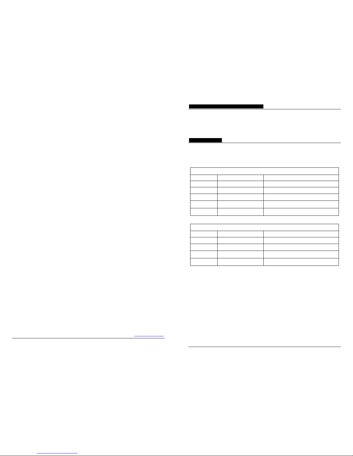
Chart 1. Obstacle Distance, Alert Zones, and Audible Alert
Reversing
Alert Zones Obstacle Distance Beeping (Audible Alert)
Safe Zone
2.0~1.5m Starting to beep at 2.0m
Safe Zone
1.5~1.0m Beeping Fast to Faster
Safe Zone
1.0~0.6m Beeping Faster to Fastest
Warning Zone
0.6~0.3m Beeping Fastest
Stop Zone
0.3~0.0m Beeping Continuously
Forward-Parking
Alert Zones Obstacle Distance Beeping (Audible Alert)
Safe Zone
1.2~1.0m Starting to beep at 1.2m
Safe Zone
1.0~0.6m Beeping Faster to Fastest
Warning Zone
0.6~0.3m Beeping Fastest
Stop Zone
0.3~0.0m Beeping Continuously
Note: 1meter = 3.3feet
Detection Range of the System
The parking sensor system detects obstacle by emitting ultrasonic wave and receiving reflected ultrasonic wave from an
obstacle. Different materials have different reflection and absorption of the ultrasonic wave, and the actual detection distance
varies depending on what materials an obstacle is composed of. Human skin and clothes actually absorb the ultrasonic wave,
and can only reflect very small portion of the ultrasonic wave back to the sensors, hence the system may detect human skin
and clothes within a much shorter range compared to other materials. Drivers in these situations should pay more
attention while parking their vehicles.
 Loading...