

Page 1

User’s Manual
Backup Parking Sensor System
Wireless Digital Display with Built-in Audible Alert
For Cars, VANs, SUVs, and Trucks
4 Rear In-Bumper Type Sensors
MODEL B-2681-04, B-2691-04
CE ISO9001
HY Technologies y http://parkingsensors.net y http://parking-sensors.hyt.com
Copyright 8 2006 HY Technologies y Milpitas y California y USA All Rights Reserved
Page 2

Backup Parking Sensor System
4 Rear In-Bumper Type Sensors
Wireless Digital Display with Built-in Audible Alert
For Cars, VANs, SUVs, and Trucks
MODEL B-2681-04, B-2691-04
Included in the Box
¾ 4x Sensors with attached cable and 2-pin mini
connector. Cable Length: 2.5m (8.2ft)
¾ 1x Main Control Box with double-sided
self-adhesive and Velcro attachment
¾ 1x Wireless Digital Display with double-sided
self-adhesive on the bottom of the base
Features
¾ 4 Rear Sensor Backup Parking System
¾ In-bumper type sensors to give the look of factory
installed system
¾ System works when vehicle is in reverse
¾ Wireless Digital Display with Built-in Audible Alert
(Beeper)
Specifications
¾ CE and ISO9001 Approved
¾ Wireless Display RF Range: 0~20m (65.6ft)
¾ RF Frequency: 433KHz
¾ Operating Voltage: DC 10V ~ 15V
¾ Detecting Range: 0.3m ~ 2.0m (1ft ~ 6.6ft)
Displayed as 0.0 when less than 0.3m (1ft)
¾ Measuring Error: ± 0.1m (0.3ft)
¾ Sensor Detection Angle: 90°
¾ Detection Response Time: 300ms
¾ Audible Alert when obstacle within: 0.1m ~ 1.5m
(0.3ft ~ 4.9ft)
¾ 1x Drill Bit - Φ22.3mm (7/8”)
¾ 1x Power Cable for Wireless Digital Display with
earphone type plug. 2.5m (8.2ft) long
¾ 1x Power Cable for Main Control Box with 4-pin
plug and 5A fuse. 2.5m (8.2ft) long
¾ 1x User’s Manual
¾ 7 LED Lights (Green/Yellow/Red) on each side of the
display indicating orientation of obstacles and
Safe/Warning/Stop zone
¾ Designed for cars, VANs, SUVs, and trucks
¾ Distance display in meters
¾ 12 Month Warranty
¾ Sensor Diameter: Φ22.3mm (7/8”)
¾ Ultrasonic Frequency: 40Khz
¾ Audible Alert Volume: 73 db
¾ Maximum Power Consumption: 3W
¾ Current Consumption: 100~300mA
¾ Operating Temperature Range: -30 ~ +70°C
¾ Dimensions of the Wireless Display: Width x Depth x
Height = 8.6cm x 3.2cm x 2.1cm (3.4" x 1.3” x 0.83")
¾ Dimensions of the Main Control Box: Width x Depth x
Height = 9.0cm x 7.0cm x 2.3cm (3.5” x 2.7" x 0.91")
Note: The specifications are for reference only. They may be changed without prior notice.
Tools Needed
Φ22.3mm (7/8”) drill bit (include), drill, tape measure, chalk or marker, wire stripper, vinyl electrical tape,
cable/wire ties, voltage meter, screw driver set, pliers.
Note: Use a bi-metal 22.3mm (7/8") drill bit (not included) if drilling through metal bumpers.
- 1 -
Page 3
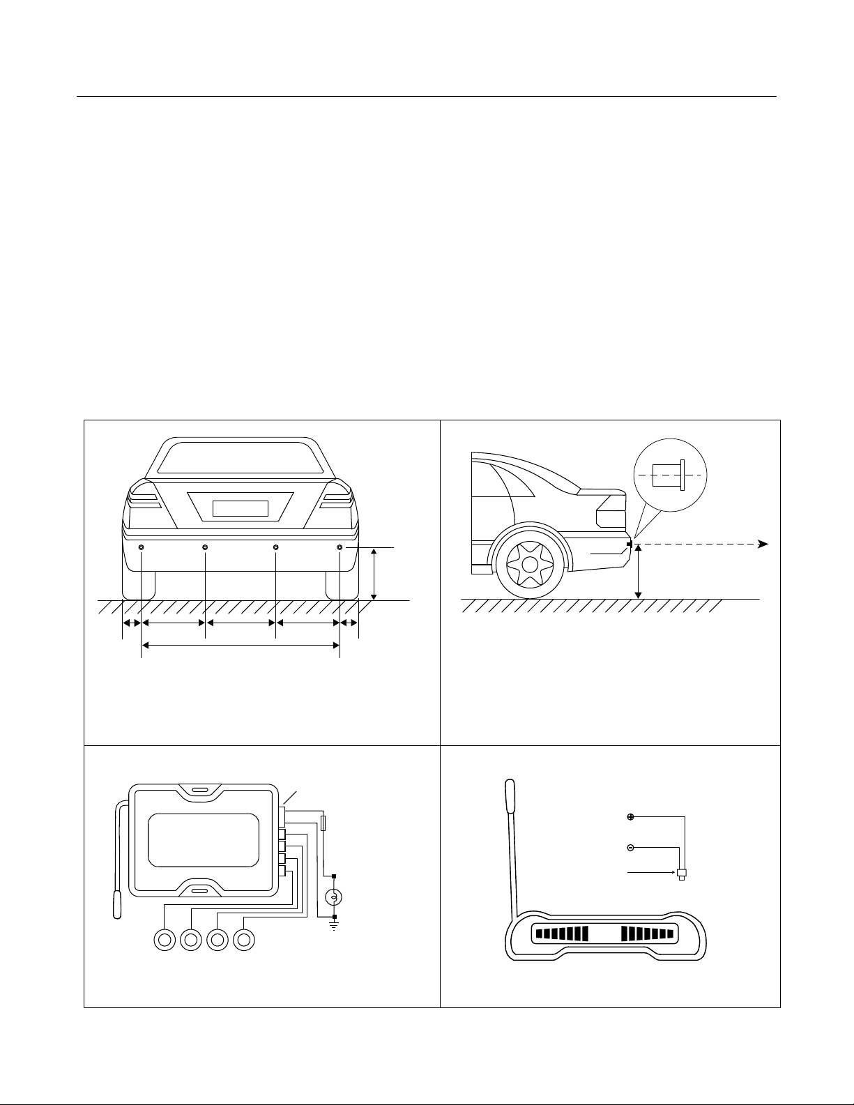
Flexible Antenna
Main Control Box
Sensors
ABCD
Red
Black
Back Up Light
Fuse (5A)
0.5
L
R
Fig.4 Front View of Wireless Digital Display
Flexible Antenna
Fig. 3 Main Control Box and Wiring
+12V from
Reverse Gear or
Ignition Switch
Chassis Ground
+
-
Red
Black
(+) 12V
( - ) or Chassis
Ground
Power Plug
(Socket on back
of display)
Power Connector
Fig.1 Mounting Height and Position of Sensors
H = 50 ~ 80cm (20” ~ 32”)
L1 = 6 ~ 15cm (2” ~ 6”)
L2 = L3 = L4 or L2 = L4 = 0.3L, L3 = 0.4L
Ground
50 ~ 80cm (20” ~ 32”)
Sensor Center Line
Parallel to Ground
Sensor
Sensor Mounting Height
Fig.2 Mounting Height and Angle of Sensor
L2
H
L1 L3 L4
L1
Ground
L
A
B
CD
How the System Works
The Backup Parking Sensor System determines obstacle distance by measuring the time needed for the
ultrasonic wave emitted by a sensor to reach an obstacle and for the sensor to receive the ultrasonic wave
reflected from the obstacle. Given the speed of the ultrasonic wave, the system can then calculate and display
the distance between the sensor and the obstacle.
To have the look of factory installed system, the system comes with 4 in-bumper type sensors to be installed in
the rear bumper by drilling holes through the bumper. The main control box and the wireless display get their
power by tapping into the back up light wires so that the system will work only when vehicle is put in reverse. It
is supplied with a wireless digital display which shows the exact distance from an obstacle and eliminates the
wiring between the display and main control box. The wireless display can be mounted up to 20m (66 feet) away
from the main control box (still requires its own +12V power supply). This is especially convenient for installation
on long vehicles. Seven (7) LED Lights (2xGreen/3xYellow/2xRed) on each side of the wireless distance
display indicate both orientation of obstacles and Safe/Warning/Stop zone. The audible alert (beeper) is built in
the wireless display. It beeps faster as vehicle gets closer to obstacle and sounds continuously when vehicle is
within 0.3m (1ft) from the obstacle.
- 2 -
Page 4

Installation and Wiring
IMPORTANT: (a) Read this manual thoroughly before proceeding to installation. You can also have the system
installed by a professional installer such as your local auto mechanic/auto electrician/car stereo store. (b) Turn off
the engine and ACC during installation. (c) Double check that all wiring is correct before power on the system. (d)
During installation, avoid flatting, perforating, cutting, and extending the wires of sensors to reduce unnecessary
signal loss.
1. Installation of the Main Control Box
a) Find a flat and clean surface inside the vehicle close to driver's side taillight assembly as the main control
box gets its power from the back up light and has all the rear sensors plugged into it. For trucks, you may
install it inside the driver's side taillight assembly. Keep it away from areas of high heat, high humidity, direct
water contact, direct sunlight, and electromagnetic devices.
b) Place the main control box in place temporarily without securing it to the vehicle as you may need to adjust
the location of the main control box while wiring.
c) After completing all wiring, use the double-sided self-adhesive with Velcro attachment included to secure the
main control box to the vehicle.
2. Installation of the Wireless Digital Display
a) Find a place for the wireless display on top of the dashboard where the driver can see it easily. Place the
wireless display in place temporarily without securing it to the top of the dashboard.
b) After completing all wiring, secure it with the included self-adhesive on the bottom of the display base.
3. Wiring Power Supply to the Wireless Digital Display
a) Insert the earphone type plug of the power cable of the Wireless Display into its socket on the back of the
display.
b) Locate the +12V and the (-) negative wires from the reverse gear for the back up lights under the dashboard
or near the reverse gear.
c) Strip 1/2" of the wires found.
d) Connect the red wire of the power cable to the +12V wire (Fig. 4)
e) Connect the black wire of the power cable to the (-) negative or chassis ground (Fig. 4).
f) Wrap the connections with vinyl electrical tape.
Note: You can also connect the red wire to the ignition switch or ACC. But connecting it to the reverse gear or
back up light is better as the display only needs to work when the vehicle is put in reverse.
4. Wiring Power Supply to the Main Control Box
a) Insert the 4-pin plug of the power cable of the main control box into its socket on the side of the main control
box (Fig. 3).
b) Locate the +12V and the (-) negative wires from the back up light near the taillight assembly. If necessary,
remove the taillight assembly to locate them.
c) Strip 1/2" of the wires found.
d) Connect the red wire of the power cable to the +12V wire (Fig. 3)
e) Connect the black wire of the power cable to the (-) negative or chassis ground (Fig. 3).
f) Wrap the connections with vinyl electrical tape.
5. Installation of the Sensors
IMPORTANT: (a) To avoid false alert from the system detecting the ground, the sensors should be mounted
between 50cm to 80cm (20" to 32") above the ground and the face of the sensors need to be vertical or slightly
upward angled (Fig. 2). (b) Horizontally, the sensors should be equally spaced if possible or symmetric to the
center of the bumper. (c) The outer two sensors should be mounted about 15cm (5.9") from the corner of the
bumper for better corner coverage.
Note: The bumper surface for mounting the sensors should be as flat and vertical as possible.
a) Refer to Fig. 1 for mounting height and position of the sensors.
b) Work under the rear bumper to check the internal structure of it before marking the positions for drilling holes.
If the view is blocked, you may need to remove the bumper.
- 3 -
Page 5

c) With chalk or marker, mark the position of sensors on the rear bumper. Make sure that the sensors can be
pushed all the way in and that you can feed the wires through.
d) Drill the holes through the bumper at the marks with the Φ22.3mm drill bit included. Note: if drilling through
metal bumper, you will need a bi-metal Φ22.3mm (7/8") drill bit (not included).
e) If necessary, smooth the sharp edge of the holes with a polishing head or small round file.
f) Run the sensor wires into the holes drilled. Push the sensors into the holes. Note: When pushing in the
sensors only apply pressure at the edges, not on the middle of the sensor to avoid damage to the sensor
element. The sensors are tapered for a snug fit.
g) Adjust the sensors for non-vertical bumper surface by rotating the sensors themselves (Fig.2). The sensors
are made with wedge-shaped edge for this purpose.
h) Run the sensor wires from the bumper into the trunk or inside of the vehicle through the existing small vent
or rubber grommet in the rear of the trunk or vehicle, and to the main control box. Note: Do not cut the
sensors wires.
i) Attach sensor wires to the vehicle body with cable/wire ties so that they will not get in the way of any moving
parts and there are no loose wires hanging down.
j) Plug one sensor at a time into its corresponding socket at the main control box, start the engine and put the
vehicle in reverse, the display should show the correct obstacle distance. Repeat the procedure for the
remaining sensors. Note: When you shift into reverse gear, the system will beep once indicating it is
activated.
Testing Your New Backup Parking Sensor System
Back your vehicle slowly (about 3 miles per hour) to approximately 2.5m (8.2 feet) from a flat vertical surface
such as a wall. Continue to back up slowly and check the performance against Chart 1.
Using the Wireless Digital Display
The display has a built-in beeper (audible alert). There are seven (7) LED Lights (Green/Yellow/Red) on each
side of the two-digit distance display (Fig. 4). The color LED lights have two functions: indicating the orientation of
obstacle and showing if you are in Safe/Warning/Stop zone (Chart. 1).
Chart 1. Orientation of Obstacle, Digital Distance Display, and Beeping (Audible Alert)
Viewing from the Front of the Display
Obstacle
Distance
Safe Zone
(> 2.0m)
Safe Zone
(2.0~1.5m)
Warning
Zone
(1.5~1.0m)
Warning
Zone
(1.0~0.7m)
Stop Zone
(0.7~0.4m)
Stop Zone
(0.4~0.0m)
LEDs on the Left Side
of the Display
Responding to
Sensor D or C
Beeping
Digital
Distance
Display
LEDs on the Right Side
of the Display
Responding to
Sensor B or A
Outer Green Flashing No -.- Outer Green Flashing
Outer Green on Starting to
Actual distance Outer Green on
beep at 1.5m
1 Yellow/2 Green on Fast
Actual distance 1 Yellow/2 Green on
3 Yellow/2 Green on Faster
1 Red/ 3 Yellow/2 Green
on
2 Red/3 Yellow/2 Green on
Fastest
Continuously 0.0 2 Red/3 Yellow/2 Green on
and Red flashing
Actual distance 3 Yellow/2 Green on
Actual distance 1 Red/3 Yellow/2 Green on
and Red flashing
- 4 -
Page 6

Warning
z To avoid collision with obstacle because of the inertia of vehicle while backing up/parking, keep your vehicle
speed at about 3 miles per hour and stop the vehicle immediately once you hear the continuous beeping.
This is because even if brake is applied, your vehicle will still go for some distance (inertia) before it comes to a
complete stop.
z Because the back up parking system detects obstacle by emitting ultrasonic wave and receiving reflected
ultrasonic wave from obstacle, the system may fail to give both visual and audible alert if an obstacle has
smooth ball-shaped or sloped surfaces as such surfaces may not reflect ultrasonic wave back to the sensors.
Drivers in these situations should pay more attention while parking their vehicles.
z In heavy falling rain or snow, the system may give alert as falling rain or snow may be detected as obstacles.
Keep surface of sensors clean of snow, mud, dirt, and other debris.
Troubleshooting
Problem Cause Solution
Display doesn't light up when
reversing
Display light up but system is
not detecting any obstacle
System showing distance but
no beeping or system
beeping but no distance
display
Wrong LEDs light up
Display constantly shows 0.0
or beeps continuously
No power to the display.
No power to the main control box.
Faulty display.
Check display power connection.
Check main control box power
connection.
Replace the display.
Contact Technical Support for help.
Sensors not connected.
Faulty display.
Faulty main control box.
Check sensor connection.
Replace the display.
Replace the main control box.
Contact Technical Support for help.
Faulty display.
Faulty main control box.
Replace the display.
Replace the main control box.
Contact Technical Support for help.
Sensors are plugged into the wrong
sockets at the main control box
Install the sensors in the bumper as
labeled in Fig. 1 and plug sensors
as labeled on the sensor wires into
their corresponding sockets at the
main control box (Fig. 3)
Object within 0.30m is detected Unplug all sensors, and then plug
back in one sensor at a time to find
out which sensor is causing the
problem. Adjust angle of the sensor.
Refer to 5. Installation of the
Sensors for details.
Display shows a distance and
beeps even there is no
obstacle behind
Ground is detected.
Sensor angle is low.
Sensor is installed too low (mounting
height below 0.5m)
Unplug all sensors, and then plug
back in one sensor at a time to find
out which sensor is causing the
problem. Adjust angle of the sensor.
Refer to 5. Installation of the
Sensors for details.
For more installation related questions and Frequently Asked Questions (FAQs) with answers, and
product photos, visit our Web site at http://parkingsensors.net
or http://parking-sensors.hyt.com
- 5 -
Page 7

IMPORTANT
The Parking Sensor Systems sold and distributed by HY Technologies are only a device used to assist a driver
while parking. They should not be considered as a substitute for driver responsibility when operating a vehicle.
No warranty as to operational efficiency is granted. We don't guarantee or assume liability for collisions or
damages that take place when parking your vehicle with the use of the Parking Sensor System. We will not be
liable for any claims, actions, suit proceedings, costs, expenses, damages or liabilities arising out of the use of
this product. By purchasing, installing and using such a Parking Sensor System, customers agree to take full
responsibility of use of such System.
HY Technologies y http://parkingsensors.net y http://parking-sensors.hyt.com
Copyright 8 2006 HY Technologies y Milpitas y California y USA All Rights Reserved
- 6 -
 Loading...