

Page 1

Contents
General.....................................................................................................................................................1
Radio Overview ........................................................................................................................................2
Software Specifications ............................................................................................................................5
Circuit Description ....................................................................................................................................6
CPU Pins................................................................................................................................................13
TC-780 VHF Parts List 1 (Main Board Unit) ...........................................................................................18
TC-780 UHF Parts List 1 (Main Board Unit) ...........................................................................................18
TC-780 VHF/UHF Parts List 1 (Keyboard Unit) ......................................................................................18
Adjustment Description...........................................................................................................................18
Troubleshooting Flow Chart ...................................................................................................................27
Disassembly and Assembly for Repair ...................................................................................................32
Exploded View........................................................................................................................................36
TC-780 Parts List 2.................................................................................................................................37
Packing...................................................................................................................................................39
TC-780 VHF PCB View ..........................................................................................................................41
TC-780 UHF PCB View..........................................................................................................................41
TC-780 VHF/UHF PCB View..................................................................................................................41
TC-780 Block Diagram ...........................................................................................................................41
TC-780 VHF Schematic Diagram ...........................................................................................................41
TC-780 UHF Schematic Diagram...........................................................................................................41
TC-780 VHF/UHF Schematic Diagram...................................................................................................41
Specifications .........................................................................................................................................42
Page 2

TC-780 Service Manual
General
Manual Scope
This manual is intended for use by experienced technicians familiar with similar types of communication
equipment. It contains all service information required for the equipment and is current as of the
publication date.
Safety and General Information
The following general safety precautions as would normally apply, should be observed during all phases
of operation, service and repair of this equipment.
z This equipment should be serviced by qualified technicians only.
z Use only HYT supplied or approved antenna.
z Turn off your radio prior to entering any area with a potentially explosive atmosphere.
z To avoid electromagnetic interference and/or compatibility conflicts, turn off your radio in any
facility where posted notices instruct you to do so.
z When instructed to do so, turn off your radio when on board an aircraft. Any use of a radio must
be in accordance with airline regulations or crew instructions.
z To avoid possible interference with blasting operations, turn off your radio when you are near
electrical blasting caps, in a blasting area, or in areas posted: “Turn off two-way radio.” Obey all
signs and instructions.
z For vehicles with an air bag, do not place a radio in the area over an air bag or in the air bag
deployment area.
z Do not use any portable radio that has a damaged antenna. If a damaged antenna comes into
contact with your skin, a minor burn can result.
z Do not expose the radio to direct sunlight over a long time, nor place it close to heating source.
z If you wear a radio on your body when transmitting, ensure that the radio and its antenna are at
least 2.5cm away from your body.
1
Page 3
TC-780 Service Manual
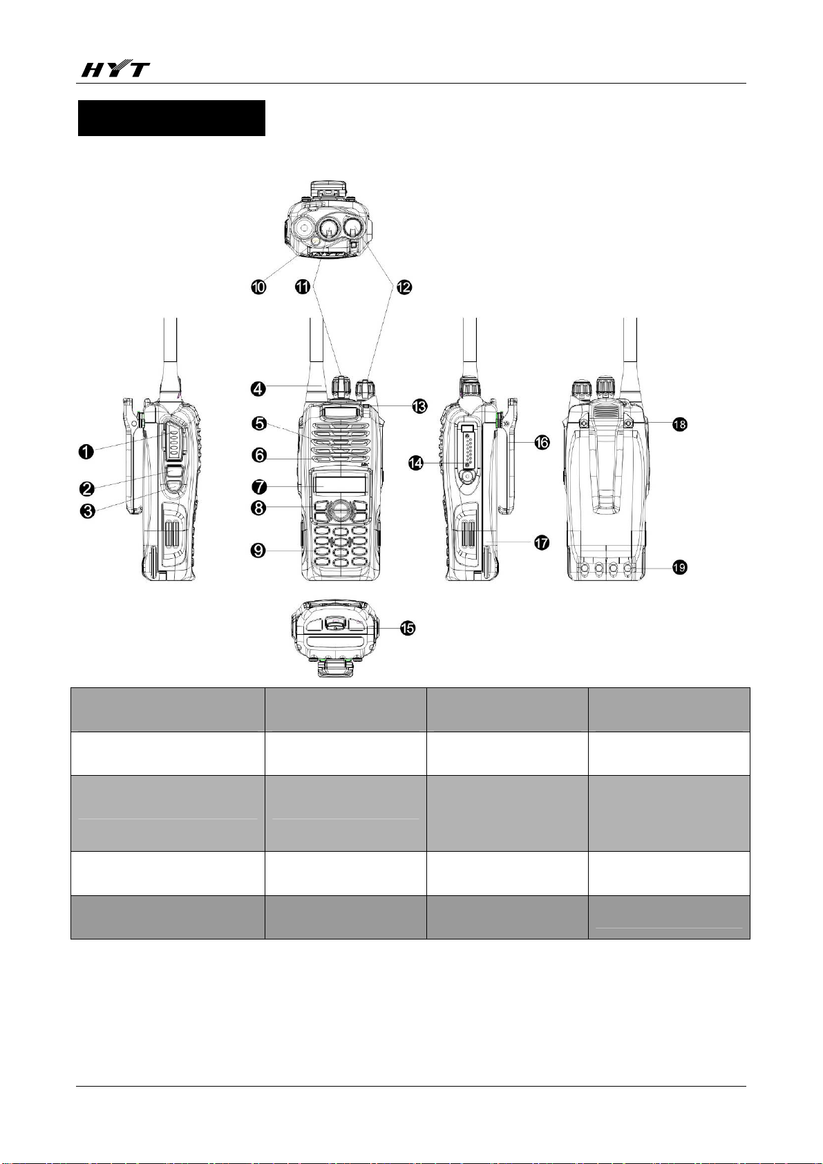
Radio Overview
1 PTT (Push-to-Talk) Key ○2 SK1 (Side Key 1) ○3 SK2 (Side Key 2) ○4 Antenna
○
5 Microphone
○
9 Numeric Keypad
○
13 LED Indicator
○
17 Battery
○
﹡PTT (Push-to-Talk) Key
Press and hold down the PTT key to transmit; release it to receive.
﹡SK1 (Side Key 1)
6 Speaker
○
10 TK (Top Key)
○
14 Accessory Jack ○15 Battery Latch
○
18 Screw, Belt Clip ○19 Charging Piece
○
7 LCD Display
○
11 Channel Selector
○
Knob
8 Function Keypad
○
12 Radio On-Off
○
/Volume Control Knob
16 Belt Clip
○
2
Page 4
TC-780 Service Manual
Programmable function key.
﹡SK2 (Side Key 2)
Programmable function key.
﹡LCD Display
Used to display radio status information.
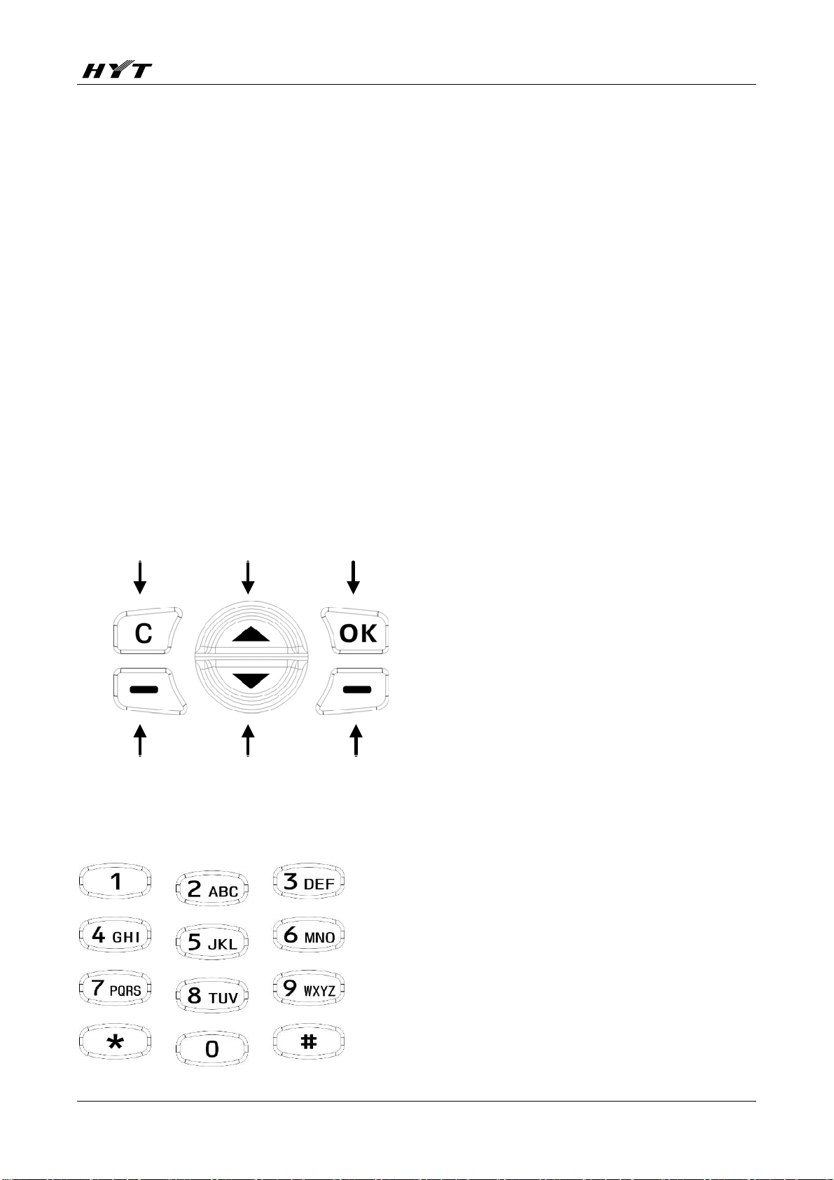
﹡Function Keypad
z Exit key
Use the Exit key to return to the previous menu.
z Up key
z Down key
z Menu/Select key
Used to enter the menu mode. When you are in the menu mode, this key is also used to make menu
selections.
Exit Up Menu/Select
Call Back Down Redial
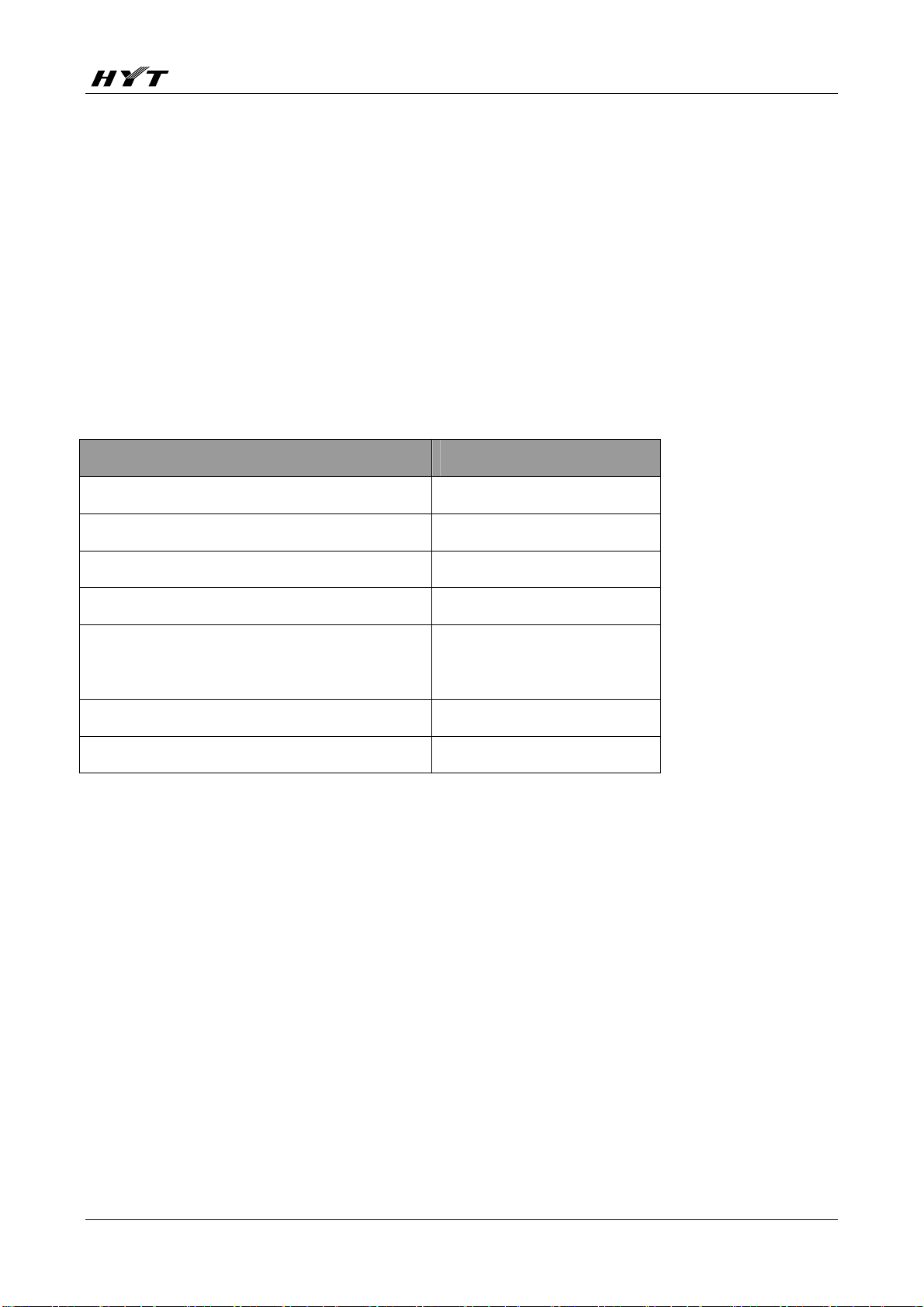
﹡Numeric Keypad
Used to enter information for programming the radio’s lists.
﹡TK (Top Key)
3
Page 5
TC-780 Service Manual
Programmable function key.
﹡Channel Selector Knob
Rotate the knob to select a desired channel.
﹡Radio On-Off/Volume Control Knob
Rotate the knob clockwise to turn the radio on, and rotate the knob fully counter-clockwise until a click is
heard to turn the radio off.
Turn the knob clockwise to increase the volume, or counter-clockwise to decrease the volume.
﹡LED Indicator
The following table indicates LED mode and corresponding radio status:
Status LED
Transmit Red
Receive Green
Low battery alert
Flash red
After transmitting a call (within auto reset time) Orange
After receiving a call (within auto reset time) Flash orange slowly
Missed call alert
Flash orange rapidly
Scan Flash green
﹡Accessory Jack
The jack is used to connect audio accessories, or other accessories such as programming cable.
4
Page 6

TC-780 Service Manual
Software Specifications
Specifications
z 256 Conventional Channels
z 32 Channel Groups
TM
z 2-Tone/DTMF/HDC1200/HDC2400
z ATIS Encode
z Priority Channel Scan
When the radio operates in talkaround mode, the channel scan feature provides users with an easy way
to monitor and join other channels.
a) Revert Channel
Press of the PTT during radio scanning shall cause the radio to transmit on the programmed revert
Encode & Decode
channel.
b) Nuisance Channel Delete
To ensure accurate scanning, press the Nuisance Channel Delete key to temporarily remove the
nuisance channel from the current scan list.
z Busy Channel Lockout
A channel already in use is not available to other users.
z Programmable Function Buttons
Six of the radio’s buttons can be programmed as shortcut buttons for your most often used features.
z Time-out Timer
The feature allows for more efficient use of channels by limiting the amount of time of each transmission.
The range is from 15 seconds to 600 seconds.
z Emergency
Press the Emergency key to emit emergency alarm, or send ENI (Emergency Number Identity) /
background tone to a pre-defined person or the dispatch center, whichever is defined by the Emergency
option. Press the button again to cancel the emergency procedure.
z VOX
z Dual Home Channels
z Optional Functions
a) Man Down
5
Page 7
TC-780 Service Manual
b) External Scrambler
c) Patrol Record
d) GPS Function
Description
1. User Mode
This mode is for normal operation by end users.
2. All Reset Mode
Allows you to initialize tuning items, channel frequency, and conventional functions. See the
Adjustment Description section for details.
3. Clone Mode
a) Factory Wired Clone Mode
b) Dealer Wired Clone Mode
c) Factory Wireless Clone Mode
d) Dealer Wireless Clone Mode
Press SK1 and
press TK to toggle between factory and dealer modes.
4. Manual Adjust Mode
Allows you to adjust frequency deviation, power level, sensitivity, squelch level, and etc.
Note: You must select
Manual Adjust Mode
from Optional Features
in the programming
to enter clone mode; press SK2 to toggle between wired and wireless clone modes;
5. PC Adjust Mode
Allows you to adjust the radio manually or automatically via PC.
software, before you
can enter manual
Circuit Description
Circuit Composition
The overall circuit is composed of PLL-VCO circuit, transmit circuit, receive circuit, baseband processing
6
Page 8
TC-780 Service Manual
circuit, power supply circuit, and MCU control circuit.
Frequency Configuration
The receiver section utilizes double conversion. The first IF is 44.85MHz and the second IF is 455 KHz.
The first local oscillator signal is supplied by PLL and VCO circuit. The second local oscillator signal is
generated from TCXO (44.395MHz); The PLL and VCO circuit also generates the frequencies required
by the transmit section.
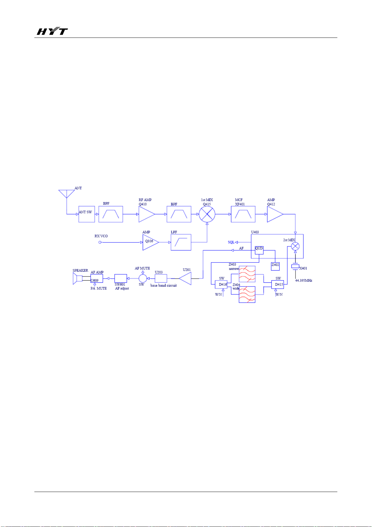
1. Receive Circuit
Configuration of the receive circuit is shown in Figure 1.
Figure 1 Receive Circuit
2. RF AMP BPF
The signal from antenna is amplified at RF amplifier (Q410) after passing through a
transmit/receive switch circuit and a band pass filter. The amplified signal is filtered by a band
pass filter to eliminate unwanted signals before it goes to the first mixer.
3. The First Mixer
The signal output by RF AMP BPF is mixed with the first local oscillator signal output by PLL frequency
synthesizer at the first mixer (Q415) to create a 44.85 MHz first IF signal. The first IF signal is then fed
through a crystal filter (XF401) to further remove spurious signals.
4. IF Amplifier
The first IF signal is amplified by Q412 and then enters U403 (TA31136FN). The signal is mixed with the
7
Page 9
TC-780 Service Manual
second local oscillator signal (44.395MHz) again to create a 455 KHz second IF signal, which passes
through a ceramic filter (wide band: Z404; narrowband: Z403) to eliminate unwanted signals. The
resulting signal is detected by U403 to output audio signal from Pin 9.
5. Audio Amplifier
The Rx audio signal output by U403 is amplified by U201, and then passes through the audio processor
U203 (the received signalling is separated from the signal for decoding). The amplified signal then is fed
to AF MUTE, volume switch SW601 (volume control) and Q615 (PA MUTE control). The resulting signal
is finally fed to the audio amplifier U609 to output audio signal from speaker.
6. Squelch
Noise signal is derived from the Rx audio signal output by Pin 9 of U403, and is processed by U403 to
produce an SQL level. The SQL level is then compared in CPU (U605) to generate a level which controls
AF MUTE and PA MUTE. It controls Q204 and Q615 to enable or disable the audio path.
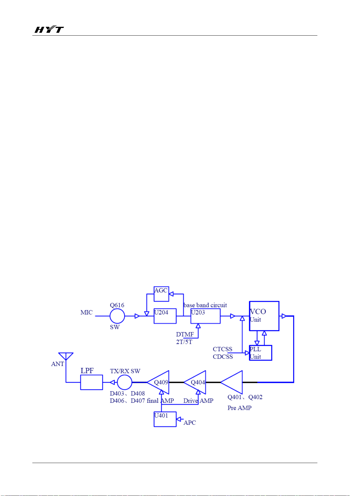
Transmit Circuit
The transmit circuit is composed of MIC circuit, frequency synthesizer, driver and final-stage power
amplifier circuit, and the APC circuit.
Figure 2 Transmit Circuit
8
Page 10

TC-780 Service Manual
1. MIC Circuit and Modulation Circuit
The audio signal from microphone is amplified by U204 after passing through the MIC control switch
(Q616). The resulting signal is then amplified, pre-emphasized and etc by U203. Simultaneously,
DTMF/2-Tone/5-Tone signallings generated by the MCU are amplified by U203, and then mixed with
MIC audio signal, and finally fed to VCO for modulation.
2. Driver and Final-Stage Power Amplifier Circuit
RF signal from local oscillator circuit is amplified by Q401 and Q402. The amplified signal is fed to the
driver stage Q404 and then the final-stage power amplifier (Q409) for amplification. The resulting signal
then passes through LPF to filter harmonics before reaching the antenna for transmit.
3. APC
The automatic power control (APC) circuit stabilizes the transmit power by detecting the drain current of
final-stage amplifier.
Frequency Synthesizer
PLL-VCO circuit generates frequency for receiving the first local oscillator signal and transmitting signals.
PLL-VCO circuit consists of Tx frequency oscillator (Q103), Rx frequency oscillator (Q101), buffer
amplifier (Q105), RF amplifier (Q107), PLL IC (U101), second harmonic circuit (Q108 and Q109) and
Tx/Rx VCO control switch (Q111, Q112, Q110 and Q102).
In transmit mode, IC120 transmits the operating frequency data to PLL IC. PLL IC is turned on to activate
Tx VCO. The outputted signal is amplified by Q703, Q124, and then divided by PLL IC (step: 2.5 KHz or
5 KHz, 6.25 KHz). The divided signal is compared with the reference signal from 16.8MHz crystal
oscillator X101 (frequency stability: 2.5ppm) in the phase comparator. The frequency control voltage
output from the phase comparator controls Tx VCO after passing through LPF. In the meantime,
modulation signal (Tx) is passed to Tx VCO for frequency modulation.
The working principle in receive mode is similar to that in transmit mode.
9
Page 11

TC-780 Service Manual
Figure 3 PLL Circuit
Control Circuit
The control circuit is comprised of MCU control circuit and power supply controller.
1. MCU
U605 (MCU) operates at 9.8304 MHz. The CPU controls data transmission among receive circuit,
transmit circuit, control circuit, display circuit and peripheral circuit.
Figure 4 Control Circuit
10
Page 12

TC-780 Service Manual
2. Power Supply
Power supply of the radio is derived from the battery that supplies battery B+ after passing through fuse,
and then passes through power switch. MCU controls power management IC (U602, U603, and U604)
to generate voltage including C5V, 5CNS, R5V, T5V.
Figure 5 Power Switch Circuit
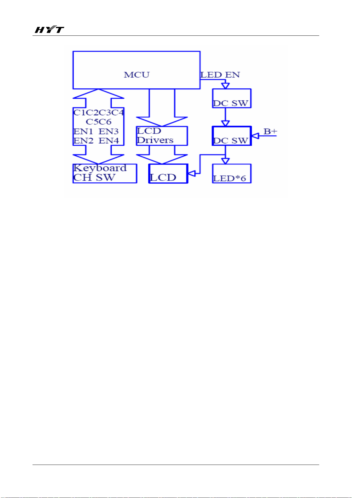
Keypad and Display Circuit
The display circuit is comprised of MCU (U605), LCD module, keyboard, LED and other components.
The backlight enable pin LED_EN is controlled by MCU. When the pin LED_EN is H, the backlight shall
be turned on.
11
Page 13
TC-780 Service Manual
Figure 6 Display Circuit
12
Page 14

TC-780 Service Manual
CPU Pins
No. Port Name Pin Name I/O Function Remarks
Automatic power control/Rx
bandpass control.
Adjust APC and Rx bandpass
1 P94/DA1 APC/TV O
2 P93/DA0 TONEO O
3 P92 LCM_SDI O
4 P91 LCM_SCK O
5 P90 TONE_IN I 2-Tone/5-Tone input decode
through DA (0-5V).
DTMF/2-Tone/5-Tone/Beep
output /ALARM output (DA
generates waveform).
Cannot output from speaker.
LCM data, display module control
data pin.
LCM clock, display module control
clock pin.
6 BYTE BYTE BYTE Ground through resistor
Pull down in operating mode, and
7 CNVSS CNVSS CNVSS
8 P87/XCIN DC_SW O
9 P86/XCOUT shift O Frequency shift
10 RESET RESET I Reset when low level input. (PROG8)
11 XOUT XOUT O
12 VSS GND I GND (PROG7)
13 XIN XIN I
14 VCC VCC I VCC (PROG1)
15 P85/NMI NMI NC
16 P84/INT2 AF_TCLK I AK2346MSK serial clock (TCLK)
17 P83/INT1 AUX1 O
pull up when programming (PROG9)
Control transmit transient.
H: disable transmit PA; L: enable
transmit PA.
Crystal oscillator output pin.
Connect to crystal oscillator.
Crystal oscillator input pin.
Connect to crystal oscillator.
Connect to VCC through 47K
resistor.
Programmable port used for future
development.
Used for future
development.
18 P82/INT0 AF_RDF I AK2346MSK Rx detect (RDF/FD)
19 P81 DTMF_SD I DTMF decode data input.
Programmable port used for future
20 P80 AUX5 I/O
21 P77 NC
22 P76/TA3O CTC_OUT O (PWM) output CTCSS/CDCSS to
development.
13
Used for future
development.
Page 15

TC-780 Service Manual
VCO for modulation.
23 P75 GPS_In I GPS input
(PWM) output CTCSS/CDCSS to
24 P74/TA2O CTC_PLL O
25 P73 AUX2 I/O
PLL for modulation.
Programmable port used for future
development.
Used for future
development.
26 P72/TA1O NC
Accessory Port
27 P71/RxD2/TB5IN
(patrol record)
Accessory Port
28 P70/TxD2
(patrol record)
Serial data output (communicate
29 P67/TxD1 TXD1 O
with computer) (PROG10)
Serial data input (communicate
30 P66/RxD1 RXD1 I
with computer) (PROG4)
For programming only.
31 P65 NC
Ground through 47K resistor. (PROG3)
For programming only; monitor
32 P64 NC
output. (PROG2)
Used for future
33 P63/TxD0 TXD0 I Connect with option board
development.
Used for future
34 P62/RxD0 RXD0 O Connect with option board
development.
I/O AT24
EEPROM DATA
35 P61 EEP_SI O AT25 EEPROM data input
input/output
36 P60 EEP_CLK O AT25/AT24 EEPROM clock pin
1: 1M EEPROM; 0:512K
37 P57/RDY EEP_ID 1
EEPROM
38 P56/ALE NC
For programming only.
39 P55/HOLD NC
Ground through 47K resistor. (PROG) 6
AK2346 DIR. Control the I/O of
data transmission.
H: output control word; L: read
40 P54/HLDA AF_DIR O
data.
41 P53/BLCK AF_SCK O AK2346 SCLK
42 P52/RD NC O
AK2346 TDATA. MSK data output
43 P51/BHE AF_TDATA O
pin.
For programming only.
Connect to VCC through 47K
44 P50/WR NC
resistor. (PROG) 5
14
Page 16

TC-780 Service Manual
AK2346 DATA I/O(SDAT).
45 P47/CS3 AF_DIO I/O
Output control word or read data.,
Control power supply.
H: supply power; L: soft power
46 P46/CS2 SBC O
down.
Battery save control.
47 P45/CS1 SAVE O
H: valid; L: battery save.
R5C Control power of receiver.
48 P44/CS0 R5C O
L: off; H: valid.
T5C Control power of transmitter.
49 P43/A19 T5C O
L: off; H: valid.
Control backlight.
50 P42/A18 LED_EN O
;L: off; H: valid.
51 P41/A17 C5 I/O Key 5
52 P40/A16 C6 I/O Key 6
53 P37/A15 C1 I/O Key 1
54 P36/A14 C2 I/O Key 2
55 P35/A13 C3 I/O Key 3
56 P34/A12 C4 I/O Key 4
Power on/off detect.
57 P33/A11 PWS I
H: soft power down; L: on.
58 P32/A10 DTMF_ACK O DTMF decode data read clock.
Accessory connection detect.
59 P31/A9 OPT_SEL I
H: no; L: yes.
60 Vcc VCC I VCC
Wide band control.
H: wide band path open; L: wide
61 P30/A8 W_CON O
band path closed.
62 Vss GND I GND
Control audio power amplifier. H:
63 P27/A7 PA_MUTE O
on; L: off.
Narrow band control. H: narrow
band path open; L: narrow band
64 P26/A6 N_CON O
path closed.
Red light control.
65 P25/A5 LEDR O
H: on; L: off.
Green light control.
66 P24/A4 LEDG O
H: on; L: off.
67 P23/A3 EN4 I EN4 Channel Selector knob 4 Original: EN2
68 P22/A2 EN3 I EN3 Channel Selector knob 3 Original: EN4
69 P21/A1 EN2 I EN2 Channel Selector knob 2 Original: EN3
70 P20/A0 EN1 I EN1 Channel Selector knob 1 Original: EN1
15
Page 17

TC-780 Service Manual
Control PLL pump current to
improve phase lock speed.
71 P17/INT5
PUMP_SW
O
H: high current; L: low current.
Rise edge is generated when the
72 P16/INT4 DTMF_EST I
decode chip detects DTMF data.
73 P15/INT3 MANDOWN I
Man down detect.
Audio path switch.
74 P14 AF_MUTE O
H: on; L: off.
Motor control.
75 P13 MOTO_CON
H: valid; L: stop.
PLL unlock detect.
76 P12 PLL_UL I
H: locked; L: unlocked.
PLL chip select output.
77 P11 PLL_STB O
H: select; L: off.
MIC switch.
78 P10 MIC_MUTE O
H: off; L: on.
79 P07/D7 PTT_EXT I External PTT input
80 P06/D6 PLL_CLK O PLL clock output
81 P05/D5 PLL_DATA O PLL data output
Tx/Rx control.
82 P04/D4 T/R O
H: Rx; L: Tx.
Control transient.
H: APC circuit works; L: APC
83 P03/D3 APC_SW O
circuit is disabled.
PTT detect.
84 P02/D2 PTT I
H: release; L: press.
B indicates the
second AK2346
(using the same
clock with the
first AK2346) (for
85 P01/D1 AK2346B_DIR I/O AK2346B register
5-Tone model)
B indicates the
second AK2346
(using the same
clock with the
first AK2346) (for
86 P00/D0 AK2346B_DATA O AK2346B data
5-Tone model)
Reserved for
patrol module.
87 P107/AN7 NC
Not used.
Determine option board according
to different levels.
88 P106/AN6 OPTION1 I
Used for future development.
16
Page 18

TC-780 Service Manual
89 P105/AN5 VOX I MIC signal input
90 P104/AN4 BATT I BATT Battery level detect.
Battery identification.
91 P103/AN3 BATTSEL I
92 P102/AN2 RSSI I RSSI detect pin.
93 P101/AN1 SQL I Squelch level input.
94 AVSS GND I
95 P100/AN0 CTC_IN I CTCSS signal input.
96 VREF VCC I A/D conversion reference voltage.
97 AVCC VCC I A/D conversion power input.
98 P97 NC
99 P96 LCM_RST O LCM reset/TP1
100 P95 LCM_CD O
Identify battery chemistry.
A/D conversion power grounded
input.
LCM_data/command
identification.
H: data; L: command.
Reserved for
patrol module.
Not used.
17
Page 19

TC-780 Service Manual
TC-780 VHF Parts List 1 (Main Board Unit)
TC-780 UHF Parts List 1 (Main Board Unit)
TC-780 VHF/UHF Parts List 1 (Keyboard Unit)
Adjustment Description
Required Test Instruments
1. Radio communication test set 1 set
2. Scanner 1 set
3. 3A/10V power supply 1 set
4. Digital voltmeter 1 set
5. 3A ammeter 1 set
Preparation
1. All Reset
1) Enter the Mode
Turn on the radio while holding down and SK1, and then release the keys to enter all reset mode.
2) Select Frequency Band
Press
3) Select Reset Type:
/ to select the corresponding frequency band, and then press .
18
Page 20

TC-780 Service Manual
“Reset function”
“Reset radioINFO”
“Reset all data”
Press
/ to select a reset type. Press
C
to return to the previous menu, or to confirm and
enter the lower level menu. When confirming initiation data, the LCD displays as follows according to the
three reset types:
"Confirm ?" "Confirm ?" "Confirm ?"
"Reset function" "Reset radioINFO" "Reset all data"
C
Press
to return to the previous menu, or to confirm and enter data initiation process. The
radio displays:
“Wirting data..."
"Please Wait"
4) After reset is completed, the radio displays “Successful”.
2. VCO
Item
Condition
Measurement Adjustment
Test
Instrument
Termin
al
Part Method
Specifications/
Remarks
1. Setting
2. Tx VCO
Lock
Voltage
3. Rx VCO
Lock
Voltage
1. Power supply
1. CH: Tx high. 3.6V±0.1V
2. CH: Tx low. Check >0.5V
1. CH: Rx high. 4.0V±0.1V
2. CH: Rx low.
Digital
Voltmeter
VCO
Adjusting
Fixture
Adjustment Procedures
1. Procedures before Adjustment
Turn on the radio while holding down SK2 and
mode.
2. Adjustment Items
CV TC114
TC104
Check >0.5V
, and then release the keys to enter manual adjust
19
Page 21

TC-780 Service Manual
The purpose of manual adjustment is to adjust Tx frequency deviation, transmit power, Rx sensitivity,
squelch, and etc.
1) SK2 Key
Set the operating frequency. Center frequency F3 is for one-point adjustment; F1, F3 and F5 are for
three-point adjustment, and F1 through F5 are for five-point adjustment. Frequency switches from low to
high in cycle.
2)
Key
Set channel bandwidth. Value switches in the cycle of 25K -> 20K -> 12.5K. The red LED glows once
when 25K is selected.
3) PTT/SK1 (or the Channel Selector knob)
Press the PTT to adjust up, and press SK1 to adjust down. You may also rotate the Channel Selector
knob clockwise to adjust up, or counter-clockwise to adjust down. Press the PTT to select a value for
items BATT LOW, SQL and VOX.
4) Select an Adjustment Item
After entering the adjustment mode, the radio enters the first adjustment item. Press
/ to select an
adjustment item and save the adjustment value of the previous item. When adjusting Tx items, LED
glows red; when adjusting Rx items, LED glows green
5) Save an Adjustment Value
After adjustment is completed, you need to press
/ to save the adjustment value and go to another
adjustment item.
6) Adjustment of Tuning Frequency Points (Tuning frequencies are set through the programming
software.)
¾ Five-point Adjustment (MHz)
TX: {TX1, TX2, TX3, TX4, TX5};
RX: {RX1, RX2, RX3, RX4, RX5}.
¾ Three-point Adjustment (MHz)
TX: {TX1, TX3, TX5};
RX: {RX1, RX3, RX5}.
¾ One-point Adjustment (MHz)
TX: {TX3};
20
Page 22

TC-780 Service Manual
RX: {RX3}.
7) Frequency Table of Five-point Adjustment
Frequency Band
(MHz)
136-174(V) TX1:136
400-470(U1) TX1:400
450-520(U2) TX1:450
Point 1 (MHz) Point 2 (MHz) Point 3 (MHz) Point 4 (MHz) Point 5 (MHz)
RX1:136.15
RX1:400.15
RX1:450.15
TX2:145.5
RX2:145.65
TX2:417
RX2:417.15
TX2:467.5
RX2:467.65
TX3:155
RX3:155.15
TX3:435
RX3:435.15
TX3:485
RX3:485.15
TX4:164.5
RX4:164.65
TX4:452
RX4:452.15
TX4:502.5
RX4:502.65
TX5:174
RX5:173.85
TX5:470
RX5:469.85
TX5:520
RX5:519.85
8) After all reset is completed, channel data corresponding to each frequency band in user mode is
shown in the following table:
Channel Rx Frequency
(MHz)
1 RX1 TX1 None High 25KHZ
2 RX3 TX3 None High 25KHZ
3 RX5 TX5 None High 25KHZ
4 RX1 RX1 None Low 20KHZ
5 RX3 RX3 None Low 20KHZ
6 RX5 RX5 None Low 20KHZ
7 RX1 RX1 None Low 12.5KHZ
8 RX3 RX3 None Low 12.5KHZ
9 RX5 RX5 None Low 12.5KHZ
10 RX3 RX3 67HZ Low 25KHZ
11 RX3 RX3 254.1HZ Low 25KHZ
12 RX3 RX3 023 Low 25KHZ
Tx Frequency
(MHz)
Signalling Power Channel
Spacing
13 RX3 RX3 754 Low 25KHZ
14 RX3 RX3 2-TONE Low 25KHZ
15 RX3 RX3 5-TONE Low 25KHZ
16 RX3 RX3 None Low 25KHZ
3. Operations and Objectives
Transmitter
Item Condition
Test
Instrument
21
Method Objective
Page 23

TC-780 Service Manual
Power in tuning
mode (Power In
tune)
Tx Low Power
(Tx L Power)
CDCSS
Balance
(DCS Pll)
CDCSS
Deviation
(DCS Dev)
CTCSS
(67.0Hz)
Low Frequency
Deviation
(CTCSS L Dev)
CTCSS
(136.5Hz)
Medium
Frequency
Deviation
(CTCSS M Dev)
Enter the adjustment
mode and select an item.
The radio transmits.
Adjust point 5 of wide
band.
Enter the adjustment
mode and select an item.
Adjust point 5 of wide
band.
Enter the adjustment
mode and select an item.
Adjust point 3 of wide
band, point 1 of medium
band and point 3 of
narrow band.
Enter the adjustment
mode and select an item.
Adjust point 3 of wide
band, point 1 of medium
band and point 3 of
narrow band.
Enter the adjustment
mode and select an item.
Adjust point 3 of wide
band, point 1 of medium
band and point 3 of
narrow band.
Enter the adjustment
mode and select an item.
Adjust point 3 of wide
band, point 1 of medium
band and point 3 of
narrow band.
Radio
Communication
Tes t S e t
TX TEST
Radio
Communication
Tes t S e t
TX TEST
HPF: 20Hz
LPF: 3kHz
PTT (up)
SK1 (down)
or
the Channel
Selector
knob
(1-255)
PTT (up)
SK1 (down)
or
the Channel
Selector
knob
(1-255)
(1-255) Make the demodulate
PTT (up)
SK1 (down)
or
the Channel
Selector
knob
(1-255)
PTT (up)
SK1 (down)
or
the Channel
Selector
knob
(1-255)
PTT (up)
SK1 (down)
or
the Channel
Selector
knob
(1-255)
Adjust power to
300±200mW
Adjust power to
1W±0.2W
waveform on the radio
communication test set
to square waveform.
Adjust frequency
deviation to 750Hz,
600Hz, 400Hz for wide,
medium and narrow
bands respectively.
Adjust frequency
deviation to 750Hz,
600Hz, 400Hz for wide,
medium and narrow
bands respectively.
Adjust frequency
deviation to 750HzHz,
600HzHz, 400Hz for
wide, medium and
narrow bands
respectively.
22
Page 24

TC-780 Service Manual
CTCSS
(254.1Hz)
High Frequency
Deviation
(CTCSS H Dev)
Tx Max Audio
Deviation
(Tx Max Dev)
2-Tone
Deviation
(Tone2 Dev)
DTMF Deviation
(DTMF Dev)
MSK Deviation
(MSK Dev)
Enter the adjustment
mode and select an item.
Adjust point 3 of wide
band, point 1 of medium
band and point 3 of
narrow band.
Enter the adjustment
mode and select an item.
Adjust point 3 of wide
band, point 1 of medium
band and point 3 of
narrow band.
Enter the adjustment
mode and select an item.
The radio transmits
(disable MSK, MIC,
DTMF, CTCSS/CDCSS).
Adjust point 3 of wide
band, point 1 of medium
band, and point 3 of
narrowband.
Enter the adjustment
mode and select an item.
The radio transmits
(disable MSK, MIC,
2-Tone, CTCSS/CDCSS).
Adjust point 3 of wide
band, point 1 of medium
band, and point 3 of
narrowband.
Enter the adjustment
mode and select an item.
The radio transmits
(disable DTMF, MIC,
2-Tone, CTCSS/CDCSS).
Adjust point 3 of wide
band, point 1 of medium
band, and point 3 of
narrowband.
Radio
Communication
Tes t S e t
Audio Test
Cable
TX TEST
HPF: 20Hz
LPF: 15KHz
Audio Signal:
1KHz 120mV
Radio
Communication
Tes t S e t
TX TEST
HPF: 20Hz
LPF: 15KHz
PTT (up)
SK1 (down)
or
the Channel
Selector
knob
(1-255)
PTT (up)
SK1 (down)
or
the Channel
Selector
knob (1-63)
PTT (up)
SK1 (down)
or
the Channel
Selector
knob
(1-255)
PTT (up)
SK1 (down)
or
the Channel
Selector
knob
(1-255)
PTT (up)
SK1 (down)
or
the Channel
Selector
knob (1-63)
Adjust frequency
deviation to 750Hz,
600Hz, 400Hz for wide,
medium and narrow
bands respectively.
Adjust frequency
deviation to 4±0.2KHz,
3.2±0.2KHz,
2.0±0.2KHz for wide,
medium and narrow
bands respectively.
Adjust frequency
deviation to
3.2±0.2KHz,
2.5±0.2KHz,
1.8±0.2KHz for wide,
medium and narrow
bands respectively.
Adjust frequency
deviation to
3.2±0.2KHz,
2.5±0.2KHz,
1.8±0.2KHz for wide,
medium and narrow
bands respectively.
Adjust frequency
deviation to
2.5±0.2KHz,
2.0±0.2KHz,
1.6±0.2KHz for wide,
medium and narrow
bands respectively.
23
Page 25

TC-780 Service Manual
VOX GAIN1
(bVox Gain Min)
VOX GAIN10
(bVox Gain
Max)
Tx High Power
(Tx H Power)
Tx Medium
Power (Tx
M Power)
Tx Low Battery Enter the adjustment
Receiver
Item Condition
Enter the adjustment
mode and select an item.
Adjust point 1 of wide
band.
Enter the adjustment
mode and select an item.
Adjust point 1 of wide
band.
Enter the adjustment
mode and select an item.
Adjust point 5 of wide
band.
Enter the adjustment
mode and select an item.
Adjust point 5 of wide
band.
mode and select an item.
Adjust point 1 of wide
band (transmitting at high
power).
Radio
Communication
Tes t S e t
TX TEST
HPF: 20Hz
LPF: 15KHz
Radio
Communication
Tes t S e t
TX TEST
Radio
Communication
Tes t S e t
TX TEST
Power Supply Save Adjust
Test
Instrument
Save Adjust the frequency to
1KHz, and amplitude to
10mv for modulation
signal, and then press
the PTT to save.
Save Adjust the frequency to
1KHz, and amplitude to
6mv for modulation
signal, and then press
the PTT to save.
PTT (up)
SK1 (down)
or
the Channel
Selector
knob
(1-255)
PTT (up)
SK1 (down)
or
the Channel
Selector
knob
(1-255)
Method Objective
Adjust power to 5W,
(4.7W) ±0.2W.
Note:
VHF: 5W
UHF: 4.7W
Adjust power to
2±0.2W
the
voltage
to 5.8V
and
then
press
the
PTT
key to
save.
24
Page 26

TC-780 Service Manual
s
f
Bandpass Waveform Enter the adjustment
mode and select the Rx
Sensitivity item. Adjust
point 5 of wide band.
Rx Sensitivity Enter the adjustment
mode and select an
item. Adjust point 5 of
wide band.
12dB Sensitivity RSSI
(RSSI 12dB)
Enter the adjustment
mode and select an
item. Adjust point 1 of
wide band and point 1
of narrow band.
AK2346 Rx Volume
Adjust
(Rx Max Volume)
Enter the adjustment
mode and select an
item. Adjust point 1 of
wide band.
Scanner
Bandpass Test
Fixture
PTT (up)
SK1 (down)
or
the Channel
Selector knob
(1-255)
Radio
Communication
Test Cable
Audio Test
Cable
RX TEST
HPF: 300Hz
PTT (up)
SK1 (down)
or
the Channel
Selector knob
(1-255)
Save Adjust the RF
LPF: 3KHz
Audio Setting:
Frequency:
1kHz
Frequency
Deviation:
3kHz
PTT (up)
Radio
Communication
Test Cable
Audio Test
Cable
SK1 (down)
or
the Channel
Selector knob
(0-8)
RX TEST
HPF: 300Hz
LPF: 3KHz
Load
Resistance:
20ohms
Adjust the bandpa
waveform to:
UHF:
VHF:
When level
adjusted to
-119dBm,
SINAD≥12Db
level of the radio
communication
test set until the
audio SINAD
gets to12dB.
Press PTT to
save the current
RSSI value.
When the
volume is
adjusted to the
maximum level,
AC Level is
adjusted to
1.8W±0.2W
(20ohms). Single
path inputs AC
Level of
3.0V±0.2V, while
dual paths input
AC Level of
6V±0.2V.
25
Page 27

TC-780 Service Manual
SQL Value of Normal
Squelch Open
(SqlNorOpen)
SQL Value of Normal
Squelch Close
(SqlNorSquelch)
SQL Value of Tight
Squelch Open
(SqlTigOpen)
SQL Value of Tight
Squelch Close
(SqlTigSquelch)
Rx Low Battery Enter the adjustment
Note: Frequency deviation
of receiver: 3 KHz for wide
band, 2.5 KHz for medium
band, and 1.5 KHz for
narrow band.
Enter the adjustment
mode and select an
item. Adjust point 5 of
wide band, point 1 of
medium band, point 5
of narrow band.
Enter the adjustment
mode and select an
item. Adjust point 5 of
wide band, point 1 of
medium band, point 5
of narrow band.
Enter the adjustment
mode and select an
item. Adjust point 5 of
wide band, point 1 of
medium band, point 5
of narrow band.
Enter the adjustment
mode and select an
item. Adjust point 5 of
wide band, point 1 of
medium band, point 5
of narrow band.
mode and select an
item. Adjust point 1 of
wide band.
Radio
Communication
Test Cable
Audio Test
Cable
RX TEST
HPF: 300Hz
LPF: 3KHz
Save Adjust the level
to -120dBm and
press PTT to
save.
Save Adjust the level
to -122dBm and
press PTT to
save.
Save Adjust the level
to -117dBm and
press PTT to
save.
Save Adjust the level
to -119dBm and
press PTT to
save.
Save Adjust the
voltage of power
supply to 7.2V
and press PTT to
save.
26
Page 28

TC-780 Service Manual
Troubleshooting Flow Chart
MCU
27
Page 29

TC-780 Service Manual
MCU Check
Normal power-on
alert tone?
No
Speaker works well?
Yes
9.8304 MHz
works normally?
Yes
Q610 works
Normally?
Yes
No
Yes
`
No
The RF circuit can’t
be driven.
Replace the speaker
Read and write
available?
Replace Q610
Yes
No
Check the
control circuit
Reset
Check reading
& writing circuit
VCO
Yes
Pin10 is of
high level?
Yes
MCU works normally.
No
Check M5V
28
Page 30

TC-780 Service Manual
VCO Check
Power supply is
normal?
Yes
Oscillator
CV voltage in Rx is
normal?
Yes
Check if
Q105 outputs
normally?
Yes
Check if
feedback is
normal.
NO
NO NO
NO
`
NO
Replace Q306
Check
if Q102 works
well.
Yes
Check Q105
Check Q107
Replace
Q102
if 16.8MHz
Oscillates?
Check CPU data circuit
Transmit Circuit
Yes
Check
Yes
NO
Check power
supply circuit.
29
Page 31

TC-780 Service Manual
No output power
Check transistor,
offset voltage &
low pass network
Repair the
transmission
network
The power is
normal?
Yes
NO
The current is
normal?
Yes
NO
Power supply
works well?
Control voltage is
normal?
High
Check drive
stage
Drive stage is
normal?
NO
Check the
suited network
NO
Yes
Low
Check power
supply circuit
Check Q607
VCO
Troubleshooting
flow chart
Yes
Finished
Receive Circuit
Finished
Finished
Yes
Yes
If the power is
normal.
NO
Replace Q404
If the power is
normal.
NO
Replace Q408
30
Page 32

TC-780 Service Manual
No receive
Power
Supply of audio IC
is normal?
Yes
Baseband
IC outputs
normally?
Yes
Check volume
switch and AF
MUTE
NO
Control
voltage PA_MUTE
is normal?
NO
Replace U609
Baseband IC
inputs normally?
NO
U403 outputs
normally?
NO
The second
local oscillator is
normal?
YesNO
Replace Q615
Yes
Replace
AK2346
Yes
Check U201
NO
Replace X401
Yes
Z402 voltage
is normal?
Yes
Check IF
input and PIN16
output
Yes
Check
output of Q415
Yes
Check Q410 path
NO
NO
NO
Replace Z402
Check U403
Check VCO
31
Page 33

TC-780 Service Manual
Disassembly and Assembly for Repair
Disassemble the Radio Case
1. Remove the Radio On-Off/Volume Control knob ① and Channel Selector knob ②.
2. Lift the chassis by its bottom and pull it out of the radio case ③.
Figure 1
Disassemble the Speaker
1. After you separate the chassis from the case, turn it for a certain degree, then disassemble the
FPC from the connector on the PCB. Then remove the screw ④ on the speaker fixing ring,
and remove the speaker fixing sheet ⑤.
2. Remove the speaker ⑥ and microphone ⑦.
Note: Take care not to
damage the FPC
connecting the speaker
and the chassis.
32
Page 34

TC-780 Service Manual
Figure 2
Disassemble the Transmit and Receive Units
1. Screw out the waterproof ring ⑧, the nut ⑨, and screws ⑩ locking the keypad PCB, shown in figure 3.
Figure 3
33
Page 35

TC-780 Service Manual
2. Rotate the keypad PCB module ○11 for 180 degrees, and then remove FPC○12 and FFC○13 from the
connector on the PCB.
11
12
13
Figure 4
3. Remove the five DB head screws ○14 on the PCB, screws ○15 locking the PCB, and the screw ○16
locking the side PTT keyboard.
4. Use an electric soldering iron to remove the two leads connecting motor from the PCB, and then to
unsolder the soldering tin at the antenna connector.
5. Lift the PCB
17 and remove it from the chassis.
○
34
Page 36

TC-780 Service Manual
n
s
n
t
e
d
4
1
4
1
7
1
4
1
4
1
5
1
1
5
1
5
1
4
5
1
5
1
5
1
5
1
6
1
Figure 5
Precautions for Assembly
Assemble the Radio Case and Chassis
1. Make sure the waterproof cushion surrounding the chassis is well fitted into the slot ① of the chassis.
2. Correctly position and assemble the speaker on the radio case ②.
Note: Make sure that the
speaker is fully assembled i
the radio case.
3. Fix the speaker sheet to the speaker, and secure it with screw ③.
4. Insert the top of the chassis into the radio case ④.
Note: Never have the speak
magnetic core being presse
5. Press the bottom of the chassis downwards to fit the chassis
the FPC.
into the radio case.
Note: If the chassis is
assembled into the radio ca
while the waterproof ring is
in position, use your fingers
place it at the right position.
35
Page 37

TC-780 Service Manual
Exploded View
Figure 6
36
Page 38

TC-780 Service Manual
5
2
1
44
43
3
4
42
41
6
40
39
8
7
38
9
37 36
11
10
12
35
1413
34
1615
17
32
33
19
18
31
30
21
20
22
23
24
25
26
27
28
29
TC-780 Parts List 2
No. Material No. Description Qty.
1 6000135000000 PTT key cover (RoHS) 1
37
Page 39

TC-780 Service Manual
2 6100068000000 PTT key (silica rubber) (RoHS) 1
3 6100319000000 Emergency key (silica rubber) (RoHS) 1
4 7500210000000 Adhesive tape, light guide 3M(9448) (RoHS) 1
5 6000609000000 Light guide (RoHS) 1
6 7400208000000
Felt, speaker PES+PBO(U500PBO) ¢40.0 (RoHS)
1
7 5001210000170 Speaker 20Ω 1W/3W 90dB Φ40mm H5.0mm (RoHS) 1
8 6201545000000 Fixing sheet, speaker (RoHS) 1
9 7102003500200 Machine screw M2.0*3.5mm (RoHS) 4
10 7500230000000 Upper sponge, LCD (RoHS) 1
11 5110000000410 LCD module (RoHS) 1
12 7102504000400 DB head screw (screw 2.5*4, nut 2.0*3) (RoHS) 5
13 7102004021030 Self-tapping screw ST1.9*4.0mm (RoHS) 12
14 4210015000000 FPC (4Pin) 0.8T*30mm (RoHS) 1
15 5402001000010 Vibrating motor (RoHS) 1
16 4305030000050 E rotary switch (RoHS) 1
17 4302020000040 Volume switch (RoHS) 1
18 4100710200100 Side PTT keyboard (RoHS) 1
19 7500114000000 Cooler pad (RoHS) 1
20 4400000000000 SMA connector, male, 50Ω (RoHS) 1
21 6100316000000 O_Ring (RoHS) 1
22 6000608000000 Rear cover PC(EXL9330) (RoHS) 1
23 6100069000000 Waterproof ring, volume control knob (RoHS) 2
24 7206004200000 Nut M6.0*4.2mm (RoHS) 2
25 6100322000000 Waterproof ring, battery connector (RoHS) 1
26 5202003100150 Battery connector (RoHS) 1
27 6100290000000 Waterproof ring, expansion port (RoHS) 1
28 7102504000300 Machine screw M2.5*4.0mm (RoHS) 1
29 6201507000000 Cover, expansion port (RoHS) 1
30 6100318000000 Waterproof ring (RoHS) 1
31 6300050000000 Aluminum chassis ADC12 (RoHS) 1
32 7500219000000 Motor (RoHS) 1
33 6201543000000 Sheet, motor (RoHS) 1
34 1300007100020 TC-780 PCB 1
35 4100710100100 FFC (14Pin) (RoHS) 1
36 1300007100030 Keyboard 1
37 7300028000000 Metal dome, function key (RoHS) 1
38 6000198000020 Earpiece jack (RoHS) 1
39 7400128010100 Waterproof PC pad (RoHS) 1
40 41007101002C0 FPCB (20Pin) (RoHS) 1
41 6000680000000 Battery latch (RoHS) 1
42 7000036000000 Spring (RoHS) 2
43 6000612000000 Front cover PC(EXL9330)+PMMA(CP-61) (RoHS) 1
44 6100317000000 Numeric keypad (RoHS) 1
38
Page 40

TC-780 Service Manual
Packing
39
Page 41

TC-780 Service Manual
40
Page 42

TC-780 Service Manual
TC-780 VHF PCB View
TC-780 UHF PCB View
TC-780 VHF/UHF PCB View
TC-780 Block Diagram
TC-780 VHF Schematic Diagram
TC-780 UHF Schematic Diagram
TC-780 VHF/UHF Schematic Diagram
41
Page 43

TC-780 Service Manual
Specifications
General
Frequency Range
Channel Capacity
Channel Spacing
Operating Voltage 7.4V
Battery
Battery Life (5-5-90 duty cycle)
Operating Temperature -25℃-+60℃
Dimensions (H×W×D)
(with battery, without antenna)
Weight (with antenna & battery)
Sensitivity 0.25μV(W)/0.28μV(N)
Selectivity 70(W)/60dB(N)
Intermodulation 65dB
VHF: 136-174MHz
UHF: 350-390MHz 400-470MHz 450-520MHz
256
25/20/12.5KHz
1700mAh (Li-Ion)
About 14 hours
124×54×35mm
340g
Receiver
Spurious Response Rejection 70dB
Rated Audio Power Output
Rated Audio Distortion
Frequency Stability ±2.5 ppm
RF Power Output 5W/1W
Spurious and Harmonics
Modulation Limiting 5 KHz(W)/2.5 KHz(N)
FM Noise 45/40dB
Modulation Distortion <3%
Frequency Stability ±2.5 ppm
All specifications are tested according to TIA/EIA-603, and subject to change without notice due to continuous
development.
1W
<5%
Transmitter
-36dBm<1GHz
-30dBm>1GHz
42
Page 44

TC-780 Service Manual
HYT endeavors to achieve the accuracy and completeness of this manual, but no warranty of accuracy or reliability is
given. All the specifications and design are subject to change without prior notice due to continuous technology
development. Changes which may occur after publication are highlighted by Revision History contained in Service
Manual.
No part of this manual may be copied, reproduced, translated, stored in a retrieval system, distributed, or transmitted in
any form or by any means, electronic or mechanical, for any purpose without the express written permission of HYT.
43
 Loading...