

Page 1
TC-610/620 Service Manual
58
Adjustment Description
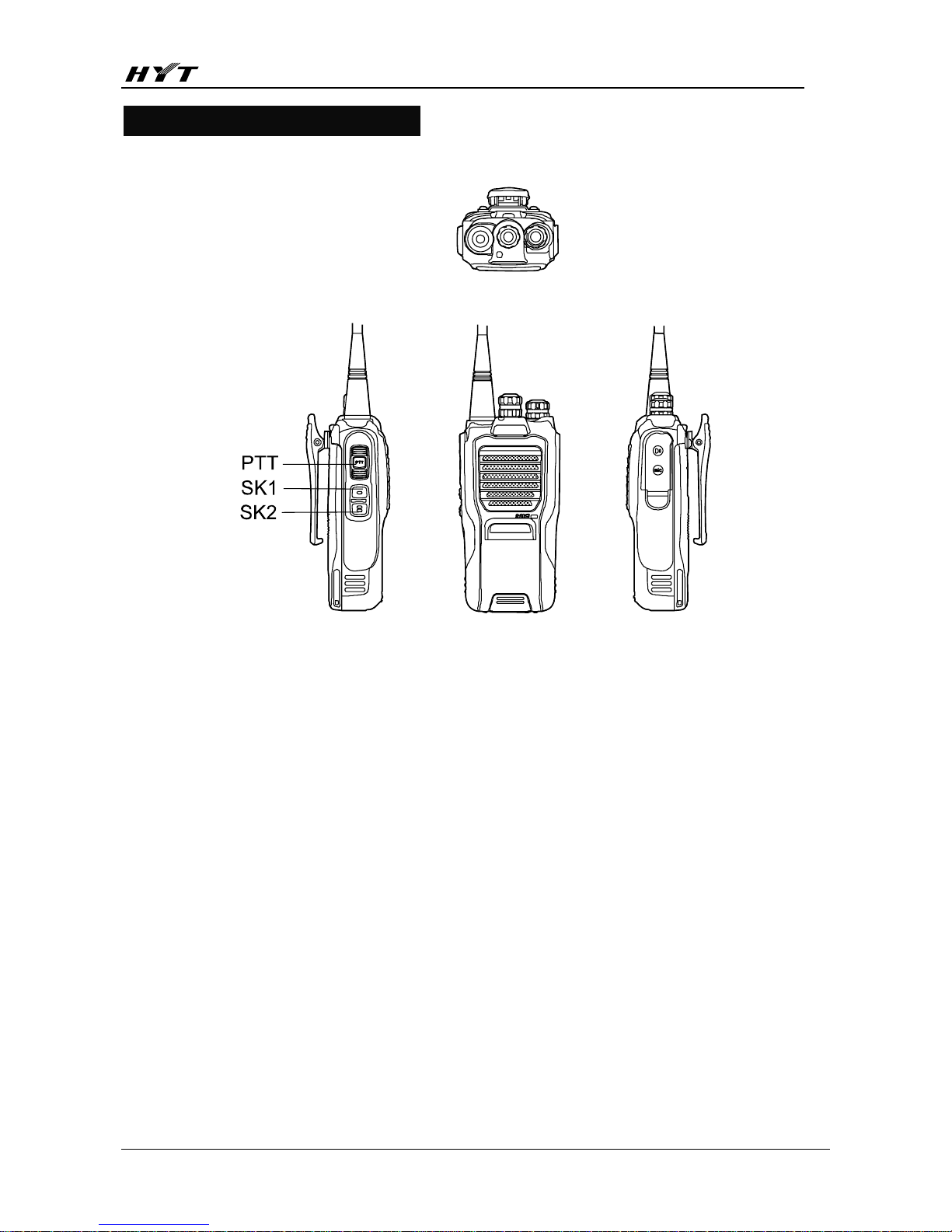
ⅠDiagram of Operation Key (Take TC-610 for example)
Ⅱ Instrument
Radio Communication Test Set (HP8921) 1 set
10V/3A DC Regulated Power Supply 1 set
Digital Voltmeter 1 set
Ammeter 1 set
Ⅲ Preparation Before Adjustment
Put the board to be tested on the test clamp and turn the power on.
Note: Each test point must be in good contact with the clamp.
Ⅳ Adjustment Steps
1. Operations Before Adjustment
1)Adjustment of PCB Board
After program is downloaded onto the PCB board and EEPROM is initialized with the configuration file
(program is downloaded with the test frame and initialization can be done through the programming
software or wired clone), check relative specifications at each position. If adjustment is required, connect
the programming cable and enter the adjustment mode for PC adjustment
2) Adjustment of Radio Unit
1. Rotate to CH1. Power on the radio while holding down the PTT key and SK2 key for 2s at least.
The orange LED (red LED + green LED) lights, indicating the entry into the adjustment mode. Release
the keys to enter the corresponding Tx adjustment item (preset power) of the adjustment mode. The red
LED lights. Adjust each specification according to the operation instructions.
2. Or connect the programming cable for real time adjustment in PC mode.
Page 2
TC-610/620 Service Manual
63
W
Rotate to CH6,
CH7 and CH8
respectively and
CTCSS is set to
low, medium and
high respectively.
Press PTT to
enable this
function.
Wide band
Short press PTT to
switch frequencies
on each channel.
Adjust VR601 with
a ceramic
alignment
screwdriver and
check each
frequency. Enter
the mode to adjust
finely with SK1/SK2
to limit the CTCSS
deviation to the
required range if
necessary.
500~900Hz (It
is
recommended
to adjust to
550-650Hz)
CTCSS
Deviation
N
Long press PTT
(≥1.5s) to enter
narrow band on
CH6, CH7 and CH8
and short press
PTT to switch
frequencies.
Radio
communication
test set
BPF:
<20Hz~300Hz
Antenna
VR601
SK1
SK2
Enter the mode to
adjust finely with
SK1/SK2 to limit
the CTCSS
deviation to the
required range if
necessary.
300~500Hz
Page 3

TC-610/620 Service Manual
63
W
Rotate to CH6,
CH7 and CH8
respectively and
CTCSS is set to
low, medium and
high respectively.
Press PTT to
enable this
function.
Wide band
Short press PTT to
switch frequencies
on each channel.
Adjust VR601 with
a ceramic
alignment
screwdriver and
check each
frequency. Enter
the mode to adjust
finely with SK1/SK2
to limit the CTCSS
deviation to the
required range if
necessary.
500~900Hz (It
is
recommended
to adjust to
550-650Hz)
CTCSS
Deviation
N
Long press PTT
(≥1.5s) to enter
narrow band on
CH6, CH7 and CH8
and short press
PTT to switch
frequencies.
Radio
communication
test set
BPF:
<20Hz~300Hz
Antenna
VR601
SK1
SK2
Enter the mode to
adjust finely with
SK1/SK2 to limit
the CTCSS
deviation to the
required range if
necessary.
300~500Hz
Page 4

TC-610/620 Service Manual
64
Rotate to
CH9.
VOX 1
Press SK1 or
SK2 to enable
the function.
Radio
communication
test set
BPF:
<20Hz~15kHz
AF:1kHz
10mV
Adjust with SK1/SK2 and
rotate the Channel
Selector knob to save
after one-point adjustment.
Rotate to
CH10.
VOX 2
Press SK1 or
SK2 to enable
the function.
Radio
communication
test set
BPF:
<20Hz~15kHz
AF:1kHz
6mV
Adjust with SK1/SK2 and
rotate the Channel
Selector knob to save
after one-point adjustment
Rotate to
CH11.
VOX 3
Press SK1 or
SK2 to enable
the function.
Radio
communication
test set
BPF: <
20Hz~15kHz
AF:1kHz
4.5mV
Adjust with SK1/SK2 and
rotate the Channel
Selector knob to save
after one-point adjustment
Rotate to
CH12
VOX 4
Press SK1 or
SK2 to enable
the function.
Radio
communication
test set
BPF: <
20Hz~15kHz
AF:1kHz
3.5mV
Adjust with SK1/SK2 and
rotate the Channel
Selector knob to save
after one-point adjustment
VOX
Rotate to
CH13.
VOX 5
Press SK1 or
SK2 to enable
the function.
Radio
communication
test set
BPF:
<20Hz~15kHz
AF:1kHz
2mV
Antenna
Accessory
jack
SK1
SK2
Adjust with SK1/SK2 and
rotate the Channel
Selector knob to save
after one-point adjustment
Tx Low
Voltage
Threshold
Digital voltmeter
Power
supply
port
Power
supply
Adjust the output voltage
of the power supply and
check the alarm level
6.2V-7.0V
(≤7.0V: LED
flashes;
≤6.2V: a
warning tone
is heard and
transmission
is suspended)
Rotate to
CH8.
Low
frequency
Rx
Sensitivity
(bandpass)
Short press
PTT to switch
to other
frequencies.
Radio
communication
test set
SSG:
-119dBm
MOD: 1KHz
DEV: 3.0KHz
Filter: 0.3~3KHz
Antenna
Accessory
jack
SK1
SK2
Check bandpass waveform
.
Adjust with SK1/SK2.
Rotate the Channel
Selector knob to save
after five-point
adjustment.
Check: Rotate
the Volume
Control knob
to an
appropriate
position to
make the
output
unlimited.
SINAD:
≥12dB
Page 5

TC-610/620 Service Manual
65
Rotate to CH1 and
SQL level 1 ON is set.
Press SK1 or SK2 to
enable the function.
The channel spacing
is wide band.
Low frequency
Short press PTT to
switch frequencies.
Radio
communication
test set
SSG: -122dBm
MOD: 1KHz
DEV: 3KHz
Filter: 0.3~
3KHz
Squelch
Level 1:
-122±1dB
Rotate to CH2 and
SQL level 5 ON is set.
Press SK1 or SK2 to
enable the function.
The channel spacing
is wide band.
Low frequency
Short press PTT to
switch frequencies.
Radio
communication
test set
SSG: -119dB
MOD: 1KHz
DEV: 3KHz
Filter: 0.3~
3KHz
Squelch
Level 5:
-119±1dB
W
Rotate to CH3 and
SQL level 9 ON is set.
Press SK1 or SK2 to
enable the function.
The channel spacing
is wide band.
Low frequency
Short press PTT to
switch frequencies.
Radio
communication
test set
SSG: 114dBm
MOD: 1KHz
DEV: 3KHz
Filter: 0.3~
3KHz
Antenna
Accessory
jack
SK1
SK2
Adjust the output
signals of SSG to
squelch level.
Rotate the
Channel Selector
knob to save
after five-point
adjustment.
Squelch
Level 9
-114±1dB
Radio
communication
test set
SSG: -121dBm
MOD: 1KHz
DEV: 1.5KHz
Filter: 0.3~
3KHz
Squelch
Level 1:
-121±1dB
Radio
communication
test set
SSG: -118dBm
MOD: 1KHz
DEV: 1.5KHz
Filter: 0.3~
3KHz
Squelch
Level 5:
-118±1dB
SQL ON
N
Long press PTT
(≥1.5s) to enter narrow
band on the above
three channels. Press
SK1 or SK2 to enable
this function. Short
press PTT to switch
frequencies.
Radio
communication
test set
SSG: -113dBm
MOD: 1KHz
DEV: 1.5KHz
Filter: 0.3~
3KHz
Same as above
Squelch
Level 5:
-113±1dB
Page 6

TC-610/620 Service Manual
66
Rotate to CH4 and
SQL level 1 OFF is
set. Press SK1 or
SK2 to enable the
function.
The channel spacing
is wide band.
Low frequency
Short press PTT to
switch frequencies.
Radio
communication
test set
SSG: -124dBm
MOD: 1KHz
DEV: 3KHz
Filter: 0.3~3KHz
Squelch
Level 1:
-124±1dB
Rotate to CH5 and
SQL level 5 OFF is
set. Press SK1 or
SK2 to enable the
function.
The channel spacing
is wide band.
Low frequency
Short press PTT to
switch frequencies.
Radio
communication
test set
SSG: -121dBm
MOD: 1KHz
DEV: 3KHz
Filter: 0.3~
3KHz
Squelch
Level 5:
-121±1dB
W
Rotate to CH6 and
SQL level 9 OFF is
set. Press SK1 or
SK2 to enable the
function.
The channel spacing
is wide band.
Low frequency
Short press PTT to
switch frequencies.
Radio
communication
test set
SSG: -116dBm
MOD: 1KHz
DEV: 3KHz
Filter: 0.3~3KHz
Antenna
Accessory
jack
SK1
SK2
Adjust the output
signals of SSG to
the squelch
level. Rotate the
Channel Selector
knob to save after
five-point
adjustment.
Squelch
Level 9:
-116±1dB
Radio
communication
test set
SSG: -123dBm
MOD: 1KHz
DEV: 1.5KHz
Filter: 0.3~3KHz
Squelch
Level 1:
-123±1dB
Radio
communication
test set
SSG: -120dBm
MOD: 1KHz
DEV: 1.5KHz
Filter: 0.3~3KHz
Squelch
Level 5:
-120±1dB
SQL OFF
N
Long press PTT
(≥1.5s) to enter
narrow band on the
above three
channels. Press SK1
or SK2 to enable this
function. Short press
PTT to switch
frequencies.
Radio
communication
test set
SSG: -115dBm
MOD: 1KHz
DEV: 1.5KHz
Filter: 0.3~3KHz
Antenna
Accessory
jack
SK1
SK2
Same as above
Squelch
Level 9:
-115±1dB
Rx
Low
Voltage
Threshold
Digital voltmeter
Power
supply port
Power
supply
Adjust the output
voltage of the
power supply
and check the
alarm level (LED
flashes red and
a warning tone is
heard)
≤6.50V
Page 7

TC-610/620 Service Manual
67
Appendix 1: Reference Software Values for TC-610/620 Source Radio
Wide Narrow
Test Items
Freq. 1 Freq. 2 Freq. 3 Freq. 4 Freq. 5 Freq. 1 Freq
. 2
Freq. 3 Freq. 4 Freq.
5
Adjust Preset Tx Power 446
Tx Low Power 742 714 692 676 672
Tx H i g h P o wer 1111 10 7 6 1 0 5 5 10 4 7 10 7 2
CDCSS Deviation 66 67 67 67 69 38 38 39 40 39
CTCSS (67Hz)
Deviation
121 125 128 131 135 69 72 72 75 77
CTCSS (151.8Hz)
Deviation
121 124 126 128 131 68 70 72 73 75
CTCSS (254.1Hz)
Deviation
133 135 137 140 143 75 77 78 78 81
VOX 1 55
VOX 2 45
VOX 3 25
VOX 4 19
VOX 5 15
Tx Low Voltage
Threshold
158
Squelch Level 1 ON 27 25 27 25 24 18 18 17 17 20
Squelch Level 5 ON 21 19 19 18 19 14 13 13 13 14
Squelch Level 9 ON 9 9 9 9 9 7 7 7 7 7
Squelch Level 1 OFF 39 30 31 32 32 27 26 24 25 26
Squelch Level 5 OFF 28 25 25 25 26 21 21 19 17 19
Squelch Level 9 OFF 12 11 12 11 13 8 8 8 8 8
Rx Low Voltage
Threshold
166
Bandpass Filter 353 401 428 470 500
Page 8

TC-610/620 Service Manual
68
Appendix 2: Reference Voltage Setting of Battery Capacity
Check in transmit mode
Green LED (70%-100%)
>7.35V
18min
Orange LED (50%-70%) 7.15V - 7.35V 12min
Red LED (30%-50%) 7.00V - 7.15V 12min
LED flashes red(<30%)
6.20V
- 7.00V
18min
LED flashes red with a warning tone
5.80V
- 6.20V
Halt <5.80V
Check in transmit and standby modes (or press the battery capacity check key.
Green LED (70%-100%)
>7.55V
18min
Orange LED (50%-70%) 7.35V -7.55V 12min
Red LED (30%-50%) 7.00V - 7.35V 20min
LED flashes red (<30%) 6.50V - 7.00V 18min
LED flashes red
and a warning tone is heard
every 10 seconds.
5.80V - 6.50V
Page 9

TC-610/620 Service Manual
69
Troubleshooting Flow Chart
Tx Section
Page 10

TC-610/620 Service Manual
70
Rx Section
Page 11

TC-610/620 Service Manual
71
MCU
 Loading...