

Page 1

TC-580 Service Manual
40
Adjustment Description
Required Test Instruments
Radio communication test set (HP8921) 1 set
10V/3A regulated DC power supply 1 set
Digital voltmeter 1 set
Ammeter 1 set
Preparation
Place the board to be tested on the test fixture (please ensure good connection between each test point
and the fixture), and connect the board to a power supply.
Tuning Procedures
1. Operations before Tuning
1) PCB Tuning:
Before the PCB arrives each work station for specification inspection, programs must be
downloaded and EEPROM must be initialized by the profiles (downloading with a test
framework/ initializing via programming software or through wired clone). If any adjustment is
required, apply a programming cable to enter the adjustment mode for PC programming or
manual adjustment.
2) Radio Tuning:
1) Manual Tuning: Hold down PTT and SK1 for 2 seconds while powering on the radio. Then
the LCD displays “Tuning Mode”. After the keys are released, press OK, and then press
UP/DN to select your desired tuning item. To enter this item, press OK again. To return to the
previous menu, press C. The LED solidly glows red for TX group items and green for RX
group items. Follow the operation instructions to tune each item.
2) Automatic Tuning: Connect a programming cable to the radio for real-time tuning through
PC.
3) Wired Clone:
1) Connect two radios using a cloning cable. Then hold down SK1 for 2 seconds while
powering the source radio on, and the radio enters Clone mode, with red LED flashing once.
The target radio can be directly turned on to enter the mode.
2) Press SK2 in Clone mode to switch to Factory Clone mode, with red LED flashing twice.
Page 2
TC-580 Service Manual
41
(Note: The Factory Clone Mode option must be checked through the programming software.)
3) Press PTT to begin cloning. During cloning, LED of the source radio glows red, while LED
of the target radio glows green. Upon completion of cloning, LED of the source radio solidly
glows orange. If any error occurs during cloning, LED of the source radio flashes orange.
Press OK to return to Clone mode upon either cloning success or failure.
4) You can clone the data to multiple target radios in the same way.
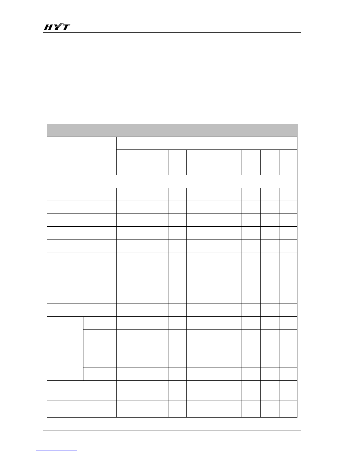
2. Description of Tuning Items
TC-580 Tuning Items
Wide Band Narrow Band
Channel
Tunable Frequency
Freq.
1
Freq.
2
Freq
. 3
Freq.
4
Freq.
5
Freq.
1
Freq.
2
Freq.
3
Freq.
4
Freq.
5
TX Section
1 Preset Power Y
2 Frequency Tolerance Y
3 TX Low Power Y Y Y Y Y
4 TX High Power Y Y Y Y Y
5 CDCSS Balance Y Y Y Y Y
6 CDCSS Deviation Y Y Y Y Y Y Y Y Y Y
7 CTCSS L Deviation Y Y Y Y Y Y Y Y Y Y
8 CTCSS M Deviation Y Y Y Y Y Y Y Y Y Y
9 CTCSS H Deviation Y Y Y Y Y Y Y Y Y Y
10 DTMF Deviation Y Y Y Y Y Y Y Y Y Y
VOX Gain 1 Y
VOX Gain 2 Y
VOX Gain 3 Y
VOX Gain 4 Y
11
VOX
Gain
VOX Gain 5 Y
12
TX Low Voltage
Threshold
Y
13
Max. Deviation of TX
Audio
Y Y Y Y Y Y Y Y Y Y
Page 3
TC-580 Service Manual
42
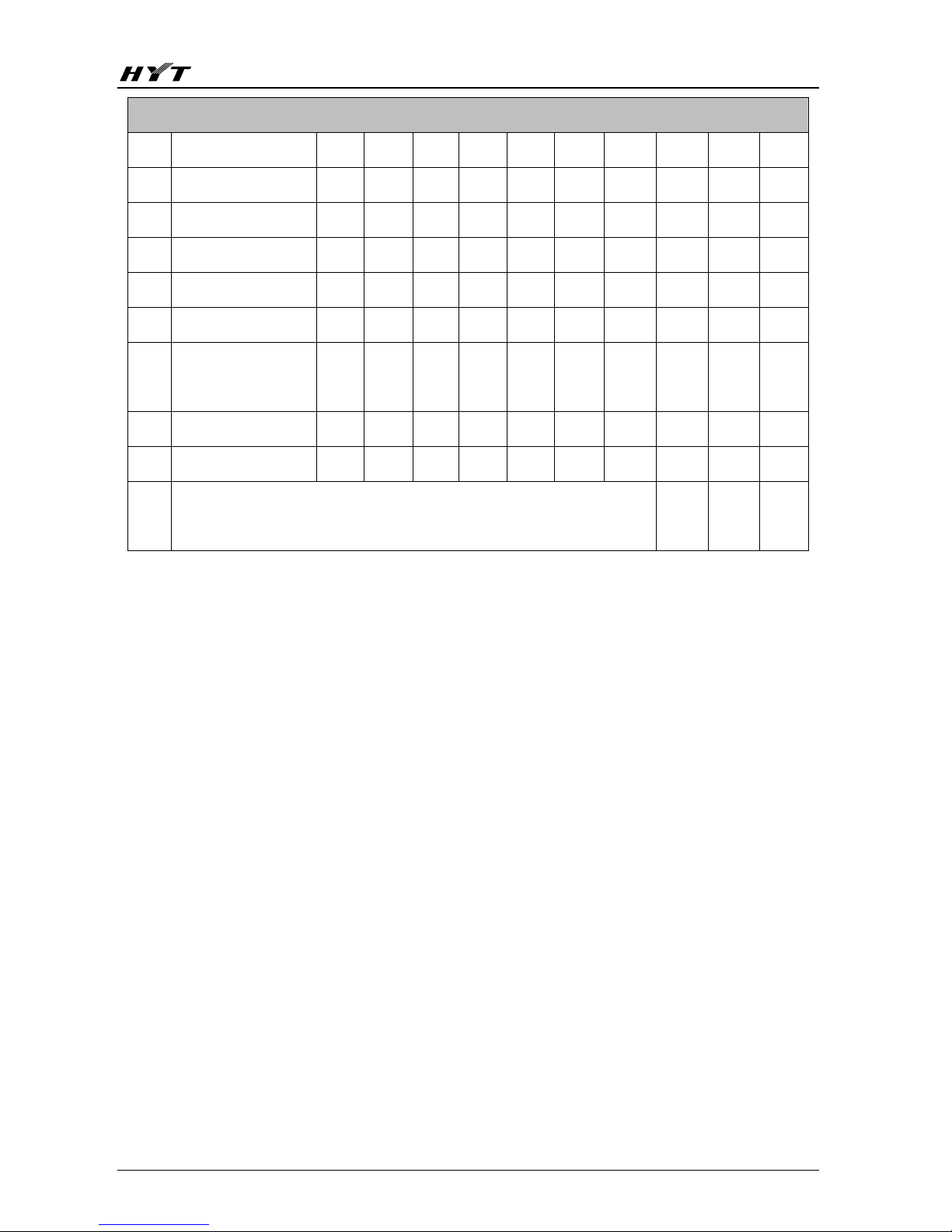
RX Section
14
SQL Level 1 ON
Y Y Y Y Y Y Y Y Y Y
15 SQL Level 5 ON Y Y Y Y Y Y Y Y Y Y
16 SQL Level 9 ON Y Y Y Y Y Y Y Y Y Y
17 SQL Level 1 OFF Y Y Y Y Y Y Y Y Y Y
18 SQL Level 5 OFF Y Y Y Y Y Y Y Y Y Y
19 SQL Level 9 OFF Y Y Y Y Y Y Y Y Y Y
20
RX Low Voltage
Threshold
Y
21 Max. RX Volume Y
22 Bandpass Filter Y Y Y Y Y
Note:
Y indicates frequencies that can be tuned, and the rest are blank
channels not available for tuning.
1) Entry into a tuning item
Hold down PTT and SK1 for 2 seconds while powering on the radio. Then the LCD displays
“Tuning Mode”. Press OK to enter the item. (Please note that TX Item is the default item.) And use
UP/DN to switch between TX Item and RX Item. After the item is selected, press OK to enter
submenu under this item. Press OK to enter the desired tuning item or press C to return to the
previous menu.
2) Wide/Narrow Bandwidth Switch and Frequency Switch in a Tuning Item
After an item is entered, press UP/DN to switch the frequency or wide/narrow bandwidth. Press OK
to save and return to the previous menu upon completion of tuning.
3) Value Tuning
Short press SK1 under certain bandwidth and certain tuning item to decrease the tuning value in
the step of 1; hold down the key to decrease the value continuously in steps of 1. The tuning value
will remain unchanged once it reaches the allowed minimum value.
Short press SK2 under certain bandwidth and certain tuning item to increase the tuning value in the
step of 1; hold down the key to increase the value continuously in steps of 1. The tuning value will
remain unchanged once it reaches the allowed maximum value.
4) Measures on special items
SQL On 5, SQL Off 5 and RX Low Voltage Threshold: These tuning items are related to AD
Page 4
TC-580 Service Manual
43
sampling. Press SK1 or SK2 after entering the above items, to activate AD sampling (including
calculation) once. Press OK to save the current AD sampling value and exit. If neither of SK1 or
SK2 is pressed, the tuning value will not be updated, and AD sampling will not be activated.
5) Description of key-press
Please refer to “Software Specifications →Description of Modes → Manual Tune Mode →
Description of key-press” on page 12.
6) Tuning Items
TX group items: include the Preset Power, Frequency Tolerance, TX Low Power, TX High Power,
CDCSS Balance, CDCSS Deviation, CTCSS Deviation (low), CTCSS Deviation
(Medium), CTCSS Deviation (high), DTMF Deviation, TX Low Voltage
Threshold and Max. Deviation of TX Audio tuned in tuning mode via software,
and VCO Lock Voltage tuned out of the tuning mode via hardware.
Rx Group Items: include the Squelch, RX Low Voltage Threshold, Max. RX Volume and RX
Bandpass Filter tuned in tuning mode, and VCO Lock Voltage tuned out of the
tuning mode.
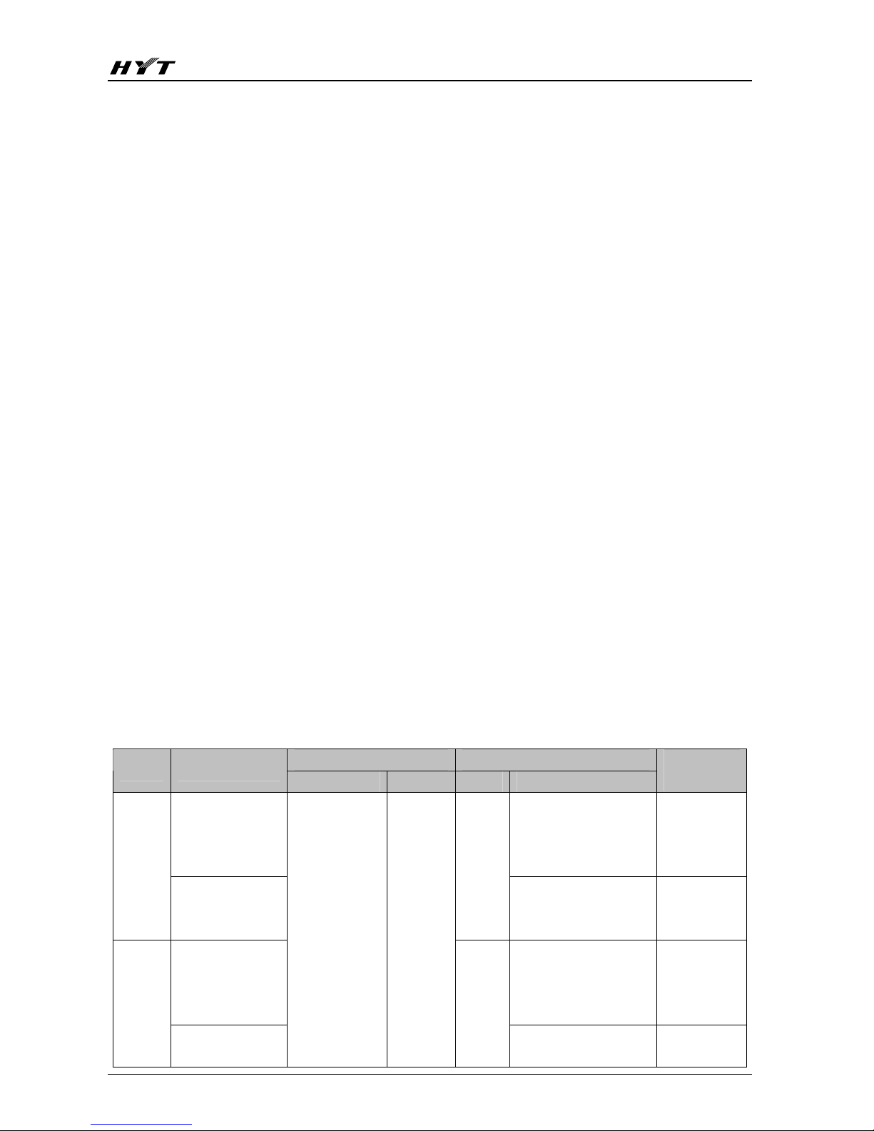
3. Specific Operations and Requirements
1) Tuning out of the mode
Note: CH1, CH2 and CH3 must be preset as wide bandwidth with low, medium and high frequency
respectively and CH4, CH5 and CH6 as narrow bandwidth with low, medium and high frequency
respectively. Make sure the antenna or load is connected before adjustment.
Tuning of TX/RX VCO Voltage
Test Adjustment
Item Condition
Test Instrument Test point Part Method
Specifications
/ Remarks
Set the channel to
CH3 and press
PTT to transmit.
Adjust TC101 with
ceramic tuning tool until
the lock voltage meets
the requirements.
4.0V±0.2V TX
VCO
Lock
Voltage
Set the channel to
CH1 and press
PTT to transmit.
TC101
Check
≥0.5V
Set the channel to
CH3.
Adjust TC102 with
ceramic tuning tool until
the lock voltage meets
the requirements.
4.0V±0.2V
Rx
VCO
Lock
Voltage
Set the channel to
CH1.
Digital
Voltmeter
CV
TC102
Check
≥0.5V
Page 5

TC-580 Service Manual
44
2) Tuning in the mode
Note: Make sure the antenna or load is connected before adjustment.
TX group items: go to tune TX items under TX Item menu.
Test Adjustment
Item Condition
Test Instrument Test point Part Method
Specifications
/ Remarks
Preset
Power
Switch to and
enter Pre Power,
and set to WFP3.
Communication
Test S e t
Antenna
Connector
Press
SK1/
SK2
Press SK1/SK2 to tune
the TX preset power
value, and press
OK to
save and exit.
1.0W
Frequency
Tolerance
Switch to and
enter Freq Offset,
and set to WFP3.
Communication
Test S e t
Antenna
Connector
Press
SK1/
SK2
Press SK1/SK2 to tune
the TX carrier frequency
tolerance, and press
OK
to save and exit.
<
300Hz
Switch to and
enter TX Power
H. WFP1 at low
frequency is set
by default.
High Power
Short press
UP/DN to switch
the frequency
(refer to the
tunable
frequencies).
Press SK1/SK2 to tune
the TX power, and press
OK to save and exit
upon completion of all
settings.
UHF:
4.0W±0.2W
I≤1.4A
VHF/245MHz
: 4.5W~5.0W
I≤1.5A
Switch to and
enter TX Power L.
WFP1 at low
frequency is set
by default.
TX Power
Low Power
Short press
UP/DN to switch
the frequency
(refer to the
tunable
frequencies).
Communication
Test Set /
Ammeter
Antenna
Connector
Press
SK1/
SK2
Press SK1/SK2 to tune
the TX power, and press
OK to save and exit
upon completion of all
settings.
1W±0.3W
I≤1.0A
Switch to and
enter CDC
Blance. WFP1 at
low frequency is
set by default.
CDCSS
Balance
Short press
UP/DN to switch
the frequency.
Communication
Test Set
BPF:
<20Hz~300Hz
Antenna
Connector
Press
SK1/
SK2
Press SK1/SK2 to tune
the CDCSS waveform,
and press
OK to save
and exit upon
completion of all
settings.
Page 6

TC-580 Service Manual
45
Switch to and enter
CDC Dev. WFP1 at
low frequency is set
by default.
Wide Band
Short press UP/DN to
switch the frequency.
700±50Hz
Tune WFP5 in CDC
Dev, and then press
UP to enter NFP1 at
low frequency.
CDCSS Deviation
Narrow Band
Short press UP/DN to
switch the frequency.
Communication
Test Set
BPF:
<20Hz~300Hz
AF Genl Lvl: off
Antenna
Connector
Press
SK1/
SK2
Press
SK1/SK2 to
tune the CDCSS
deviation, and press
OK to save and exit
upon completion of
all settings.
450±50Hz
Switch to and enter
CTC Dev L. WFP1 at
low frequency is set
by default.
Short press
UP/DN to
switch the frequency.
Low Frequency
Tune WFP5 in CTC
Dev L, and then press
UP to enter NFP1 at
low frequency.
Switch to and enter
CTC Dev M. WFP1 at
low frequency is set
by default.
Short press
UP/DN to
switch the frequency.
Medium Frequency
Tune WFP5 in CTC
Dev M, and then
press
UP to enter
NFP1 at low
frequency.
Switch to and enter
CTC Dev H. WFP1 at
low frequency is set
by default.
Short press
UP/DN to
switch the frequency.
CTCSS Deviation
High Frequency
Tune WFP5 in CTC
Dev H, and then press
UP to enter NFP1 at
low frequency.
Communication
Test Set
BPF:
<20Hz~300Hz
AF Genl Lvl:
off
Antenna
Connector
Press
SK1/
SK2
Press
SK1/SK2 to
tune the CTCSS
deviation, and press
OK to save and exit
upon completion of
all settings.
Wide band:
700±50Hz
Narrow
band:
450±50Hz
Page 7

TC-580 Service Manual
46
Wide Band
Switch to and enter
DTMF Dev. WFP1 at
low frequency is set
by default.
Short press
UP/DN to
switch the frequency.
3±0.1kHz
DTMF Deviation
Narrow
Band
Tune WFP5 in DTMF
Dev, and then press
UP to enter NFP at
low frequency.
Communication
Test Set
BPF:
<20Hz~15KHz
AF Genl Lvl: off
Antenna
Press
SK1/
SK2
Press SK1/SK2
to tune the
DTMF
deviation, and
press
OK to
save and exit
upon
completion of all
settings.
1.8±0.1kHz
Wide Band
Switch to and enter
TX Max Dev. WFP1 at
low frequency is set
by default.
Short press
UP/DN to
switch the frequency.
3.9KHz~4.1KHz
Max. Modulation Frequency Deviation
Narrow Band
Tune WFP5 in TX
Max Dev, and then
press
UP to enter
NFP1 at low
frequency.
Communication
Test Set
BPF:
<20Hz~15KHz
AF Genl Lvl:
120mV
Antenna
Earpiece
Socket
Press
SK1/
SK2
Press SK1/SK2
to tune the
audio deviation,
and press
OK to
save and exit
upon
completion of all
settings.
1.9KHz~2.1KHz
Switch to VOX Gain
and press OK to enter
its menu. Select VOX
Gain1 and enter, and
set to WFP3.
VOX Gain
In the menu of VOX
Gain, press
UP/DN to
switch among items
from VOX Gain1 to
VOX Gain5.
Communication
Test Set
BPF:
<20Hz~15KHz
AF Genl Lvl:
1.5mV
Antenna
Earpiece
Socket
Press
SK1/
SK2
Press SK1/SK2
to begin
sampling. Press
OK to save and
return to the
previous menu
upon
completion of
sampling.
VOX Gain1:
7.0mV
VOX Gain2:
4.0mV
VOX Gain3:
3.0mV
VOX Gain4:
2.5mV
VOX Gain5:
1.5mV
TX Low Voltage Threshold
Switch to and enter
TX Low Batt, and set
to WFP3.
Digital Voltmeter
Power
Supply
port
Power
Supply
Check the
value, adjust the
output voltage
and inspect the
emergency
level.
A. 6.4~6.6V: the
alert tone sounds
to indicate
transmission
inhibition upon
press of PTT.
B. ≤6.2V: the alert
tone will sound to
indicate
transmission
inhibition if
PTT is
held down.
Page 8

TC-580 Service Manual
47
RX group items: go to tune RX items under RX Item menu.
Test Adjustment
Items Condition
Test Instrument Test point Part Method
Specifications /
Remarks
Switch to and enter
BPF Tune. WFP1 at
low frequency is set
by default.
RX Sensitivity (Bandpass)
Short press UP/DN to
switch the frequency.
Communication
Test Set
SSG: -119dBm
MOD: 1KHz
DEV: 3.0KHz
Filter: 0.3~3KHz
Antenna
Earpiece
Socket
Press
SK1/
SK2
Check the bandpass
waveform and press
SK1/SK2 to adjust
the BPF Tune
waveform. Press
OK
to save and exit upon
completion of all
settings.
Adjust the
volume to an
appropriate
value before
tuning, so that
the output
amplitude is not
limited.
SINAD: ≥12dB
Switch to and enter
SQL Open5. WFP1 at
low frequency is set
by default.
Short press
UP/DN to
switch the frequency.
Squelch level
(Level 5):
-121dB
Wide Band
Refer to method of
SQL Open5 for that of
SQL Open1 and SQL
Open9.
Communication
Test Set
SSG: -121dB
MOD: 1KHz
DEV: 3KHz
Filter: 0.3~3KHz
Squelch Level:
Level 1: -124dB
Level 9: -117dB
Tune WFP5 in SQL
Open5, and then
press
DN to enter
NFP1 at low
frequency.
Squelch Level
(5):
-120dB
Squelch Open
Narrow Band
Refer to method of
SQL Open5 for that of
SQL Open1 and SQL
Open9.
Communication
Test Set
SSG: -120dB
MOD: 1KHz
DEV: 1.5KHz
Filter: 0.3~3KHz
Antenna
Earpiece
Socket
Press
SK1/
SK2
Tune the SSG
output signal to
squelch level. Press
OK to save and exit
upon completion of
all settings.
Squelch Level:
Level 1: -123dB
Level 9: -116dB
Switch to and enter
SQL Close5. WFP1
at low frequency is
set by default.
Short press
UP/DN to
switch the frequency.
Squelch level
(Level 5):
-123dB
Squelch Close
Wide Band
Refer to method of
SQLClose 5 for that
of SQL Close 1 and
SQL Close 9.
Communication
Test Set
SSG: -123dBm
MOD: 1KHz
DEV: 3KHz
Filter: 0.3~3KHz
Antenna
Earpiece
Socket
Press
SK1/
SK2
Tune the SSG output
signal to squelch
level. Press
OK to
save and exit upon
completion of all
settings.
Squelch Level:
Level 1:
-126dB
Level 9:
-119dB
Page 9

TC-580 Service Manual
48
Tune WFP5 in SQL
Close5, and then press
UP to enter NFP1 at
low frequency.
Squelch level
(Level 5):
-122dB
Squelch Close
Narrow Band
Refer to method of
SQLClose 5 for that of
SQL Close 1 and SQL
Close 9.
Communication
Test Set
SSG: -122dBm
MOD: 1KHz
DEV: 1.5KHz
Filter: 0.3~3KHz
Antenna
Earpiece
Socket
Press
SK1/
SK2
Refer to the
above.
Squelch
Level:
Level 1:
-125dB
Level 9:
-118dB
RX Low Voltage Threshold
Switch to Rx Low Batt,
and set to WFP3.
Digital Voltmeter
Power
Supply
Port
Power
Supply
Check the value,
adjust the output
voltage and
inspect the
emergency level
(red LED flashes
and alert tone
sounds).
7.0~7.2V: the
red LED
flashes and
alert tone
sounds.
Max. RX Volume
Switch to Rx Max Dev,
and set to WFP3.
Communication
Test Set
SSG: -47dBm
MOD: 1KHz
DEV: 3KHz
Filter: 0.3~3KHz
Antenna
Earpiece
Socket
Press
SK1/
SK2
Press
SK1/SK2 to
tune the maximum
volume, Press
OK
to save and exit
upon completion
of all settings.
1.3~1.5W
(2.28~2.45V)
Appendix 1: Reference Value for TC-580U Source Radio
Wide Band Narrow Band
Tuning Item
Freq. 1 Freq.
2
Freq.
3
Freq.
4
Freq.
5
Freq.
1
Freq.
2
Freq.
3
Freq.
4
Freq.
5
TX Item Section
Preset Power 167
Frequency Tolerance 608
TX Low Power 176 167 167 170 159
TX High Power 400 397 389 390 387
CDCSS Balance 89 91 110 113 89
CDCSS Deviation 101 101 117 115 115 57 61 71 73 68
CTCSS L Deviation 152 163 136 169 171 96 104 85 106 110
CTCSS M Deviation 139 151 175 170 162 89 97 110 111 101
CTCSS H Deviation 151 155 173 169 174 94 98 109 109 109
DTMF Deviation 94 96 102 102 112 55 55 59 62 63
TX Low Voltage
Threshold
202
Page 10

TC-580 Service Manual
49
VOX Gain1 71
VOX Gain2 32
VOX Gain3 20
VOX Gain4 14
VOX
Gain
VOX Gain5 4
Max Deviation of TX
Audio
16 17 18 19 22 16 17 18 20 22
Rx Item Section
SQL Level 1 ON 78 69 65 67 65 82 72 68 66 70
SQL Level 5 ON 61 50 44 44 47 64 55 48 48 48
SQL Level 9 ON 32 23 19 20 21 38 26 23 23 24
SQL Level 1 OFF 85 78 76 75 79 91 84 79 80 79
SQL Level 5 OFF 72 63 59 58 61 75 66 59 62 61
SQL Level 9 OFF 46 35 31 33 31 51 39 34 33 36
RX Low Voltage
Threshold
200
Max. RX Volume 33
Bandpass Filter 210 320 429 536 631
Note: The value is subject to that of the source radio.
Appendix 2: Reference Value for TC-580 Battery Strength
Detection in TX status
Green LED glows (70%-100%) >7.46V Duration: 18 minutes
Orange LED glows (50%-70%) 7.15V - 7.35V Duration: 12 minutes
Red LED glows (30%-50%) 7.00V - 7.15V Duration: 12 minutes
Red LED flashes (<30%) 6.20V - 7.00V Duration: 18 minutes
Red LED flashes and Alert tone sounds 5.80V - 6.20V
Radio is powered off. <5.80V
Detection in Rx and Standby status (or press the Battery Strength Indicator key)
Green LED glows (70%-100%) >7.55V Duration: 18 minutes
Orange LED glows (50%-70%) 7.35V -7.55V Duration: 12 minutes
Red LED glows (30%-50%) 7.00V - 7.35V Duration: 20 minutes
Red LED flashes (<30%) 6.50V - 7.00V Duration: 18 minutes
Red LED flashes and low battery
alert tone sounds every ten
seconds.
5.80V - 6.50V
Page 11

TC-580 Service Manual
50
Troubleshooting Flow Chart
TX Section
No transmission
Start
Normal TX
power supply?
LED of D609
glows red?
Check the TX
power
TX VCO locked? Check TX VCO
Check TX path
Replace D609
No Sound during
transmission
LED fails to
glow/flash
Check antenna
connection
Check Q402, Q403
and Q404
Yes
No
Check the APC
circuit
Low TX Power
Check the audio path
(MIC, D108)
Replace D609
Yes
No No
Page 12

TC-580 Service Manual
51
RX Section
Page 13

TC-580 Service Manual
52
MCU Section
Normal power-on alert
tone and LCD display?
Normal power-on
alert tone and LCD
display
Normal power-on
alert tone but no
LCD Display
No power-on alert
tone but normal
LCD display
No power-on alert
tone and no LCD
display
Speaker works
normally?
LCD works
normally?
Replace
LCD
Replace
speaker
Keys work
normally?
Key dome
works normally?
Other
controlling pins
work normally?
Re-download the
program or replace
MCU
MCU
operating voltage
VCC works
normally?
Check
power
supply
circuit
MCU works
normally?
Replace
dome
MCU
works
normally
Yes
No
No
Yes
No
Yes
Yes
No
No
Yes
Yes
No
No
Yes
Start
 Loading...