

Page 1
www.hytera.us
8110031 000200
TC-310 OBR
2015
Hytera Communications Corporation Limited.
Page 2

1
Preface
Thank you for purchasing Hytera’s HYT TC-310 On-Site
Business Radio. With its unique compact design and crystal clear
sound quality the HYT TC-310 OBR is the ideal radio solution
for schools, retail locations, hotel management, restaurants,
manufacturing and other small to mid-sized organizations looking
for quick, easy and dependable communications at a great value.
Note: Read this user guide carefully to ensure you know
how to properly operate the radio before use. The
information presented herein can help you to derive
optimum performance from your radio.
MODELS COVERED BY THIS MANUAL:
TC-310 OBR UHF Two-Way Radio
Page 3

Icon Information
The following icons are available through this manual:
Warning/Caution: represents important safety information, to make
users aware of misoperations that may cause malfunction of the radio,
personal injury or property damage.
Note: indicates important information which helps you make better use of
your radio.
Copyright Information
HYT is registered trademarks of Hytera Communications Corporation Limited
(the Company) in P.R.C and other countries and/or areas. Hytera retains
the ownership of its trademarks and product names. All other company and/
or product names used in this manual are trademarks and/or registered
trademarks of their respective owners.
Disclaimer
Hytera endeavors to achieve the accuracy and completeness of this manual,
but no warranty of accuracy or reliability is given. All the above specications
and designs are subject to change without notice due to continuous
development. No part of this manual may be copied, reproduced, translated,
and stored in a retrievable system, distributed, or transmitted in any form or
by any means, electronic or mechanical, for any purpose without the express
written permission of Hytera.
FCC Regulations
Federal Communication Commission (FCC) requires that all radio
communication products should meet the requirements set forth in the above
standards before they can be marketed in the U.S, and the manufacturer shall
post a RF label on the product to inform users of operational instructions, so
as to enhance their occupational health against exposure to RF energy.
Operational Instructions and Training Guidelines
To ensure optimal performance and compliance with the occupational/
controlled environment RF energy exposure limits in the above standards and
guidelines, users should transmit not more than 50% of the time and always
adhere to the following procedures:
● RF energy will be generated only when the radio is transmitting.
● The radio must be at least 2.5 centimeters away from human body when
transmitting.
Page 4

FCC License Information
This device complies with Part 15 and Part 90 of the FCC Rules. Operation is
subject to the condition that this device does not cause harmful interference.
On-Site business two-way radios operate on radio frequencies that are
regulated by the FCC. To transmit on these frequencies, you are required to
have a license issued by the FCC. Application is made available on FCC Form
601 and Schedules D, H, and Remittance Form 159. To obtain these FCC
forms, request document 000601 which includes all forms and instructions.
If you wish to have the document faxed, mailed or have questions, use the
following contact information.
Faxed contact the Fax-On-Demand system at: 1-202-418-0177
Mailed call the FCC forms hotline at:
1-800-418-FORM
1-800-418-3676
Questions regarding FCC license contact the
FCC at:
1-888-CALL-FCC
1-888-225-5322
Or: http://www.fcc.gov
Before lling out your application, you must decide which frequency (ies) you
can operate on. For questions on determining the radio frequency, please
contact us or your local dealer for more technical support.
Changes or modifications not expressly approved by Hytera may void the
user’s authority granted by the FCC to operate this radio and should not be
made. To comply with FCC requirements, transmitter adjustments should be
made only by or under the supervision of a person certified as technically
qualied to perform transmitter maintenance and repairs in the private land
mobile and xed services as certied by an organization representative of the
user of those services.
Replacement of any transmitter component (crystal, semiconductor, etc.) not
authorized by the FCC equipment authorization for this radio could violate FCC
rules.
Usage of this radio outside the country where it was intended to be distributed
is subject to government regulations and may be prohibited.
Page 5

1
Contents
Safety Information --------------------------------------------------------------------------------- 2
Product Inspection -------------------------------------------------------------------------------- 3
Radio Overview ------------------------------------------------------------------------------------- 4
Battery Information -------------------------------------------------------------------------------- 6
Antenna Information ------------------------------------------------------------------------------ 10
Assembly and Disassembly ------------------------------------------------------------------- 10
Attaching/Removing the Battery ---------------------------------------------------------- 10
Attaching/Removing the Antenna --------------------------------------------------------- 11
Attaching/Removing the Belt Clip --------------------------------------------------------- 11
Attaching/Removing the External Earpiece/Mini USB Device -------------------- 12
Basic Operations ----------------------------------------------------------------------------------- 13
Turning the Radio On/Off ------------------------------------------------------------------- 14
Adjusting the Volume ------------------------------------------------------------------------ 14
Selecting a Channel ------------------------------------------------------------------------- 14
Transmitting ------------------------------------------------------------------------------------ 14
Receiving --------------------------------------------------------------------------------------- 14
Programmable Auxiliary Functions ---------------------------------------------------------- 14
Advanced Operations ---------------------------------------------------------------------------- 15
CTCSS/CDCSS ------------------------------------------------------------------------------- 15
Battery Save ----------------------------------------------------------------------------------- 15
Time-out Timer (TOT) ----------------------------------------------------------------------- 15
Battery Strength Indicator ------------------------------------------------------------------ 16
Monitor ------------------------------------------------------------------------------------------ 16
Scan --------------------------------------------------------------------------------------------- 17
Busy Channel Lockout (BCL) ------------------------------------------------------------- 19
Low Battery Alert ----------------------------------------------------------------------------- 19
Voice-Operated Transmit (VOX) ---------------------------------------------------------- 19
Compandor ------------------------------------------------------------------------------------ 20
Scrambler --------------------------------------------------------------------------------------- 20
Troubleshooting ----------------------------------------------------------------------------------- 21
Care and Cleaning -------------------------------------------------------------------------------- 22
Optional Accessories ---------------------------------------------------------------------------- 22
Default Frequency List --------------------------------------------------------------------------- 23
Frequency and Codes Chart ------------------------------------------------------------------- 23
CTCSS AND CDCSS CODES ------------------------------------------------------------------- 25
Default Factory Feature List -------------------------------------------------------------------- 27
Hytera’s Limited Warranty for the United States and Canada----------------------- 27
Page 6

2
Safety Information
The following safety precautions shall always be observed during operation,
service and repair of this equipment.
● This equipment shall be serviced by qualied technicians only.
● Do not modify the radio for any reason.
● Use only Hytera supplied or approved batteries and chargers.
● To avoid electromagnetic interference and/or compatibility conicts, turn off
your radio in any area where posted notices instruct you to do so.
● Turn off your radio before boarding an aircraft. Any use of a radio must be
in accordance with airline regulations or crew instructions.
● For vehicles with an air bag, do not place a radio in the area over an air
bag or in the air bag deployment area.
● Turn off your radio prior to entering any area with explosive and ammable
materials.
● Do not charge your battery in a location with explosive and flammable
materials.
● Turn off your radio before entering a blasting area.
● Do not use any portable radio that has a damaged antenna. If a damaged
antenna comes into contact with your skin, a minor burn can result.
● Do not expose the radio to direct sunlight over a long time, nor place it
close to heating source.
● When transmitting with a portable radio, hold the radio in a vertical position
with the microphone 3 to 4 centimeters away from your mouth. Keep
antenna at least 2.5 centimeters away from your body when transmitting.
WARNING: If you wear a radio on your body, ensure the radio
and its antenna are at least 2.5 centimeters away from your body
when transmitting.
Page 7
3
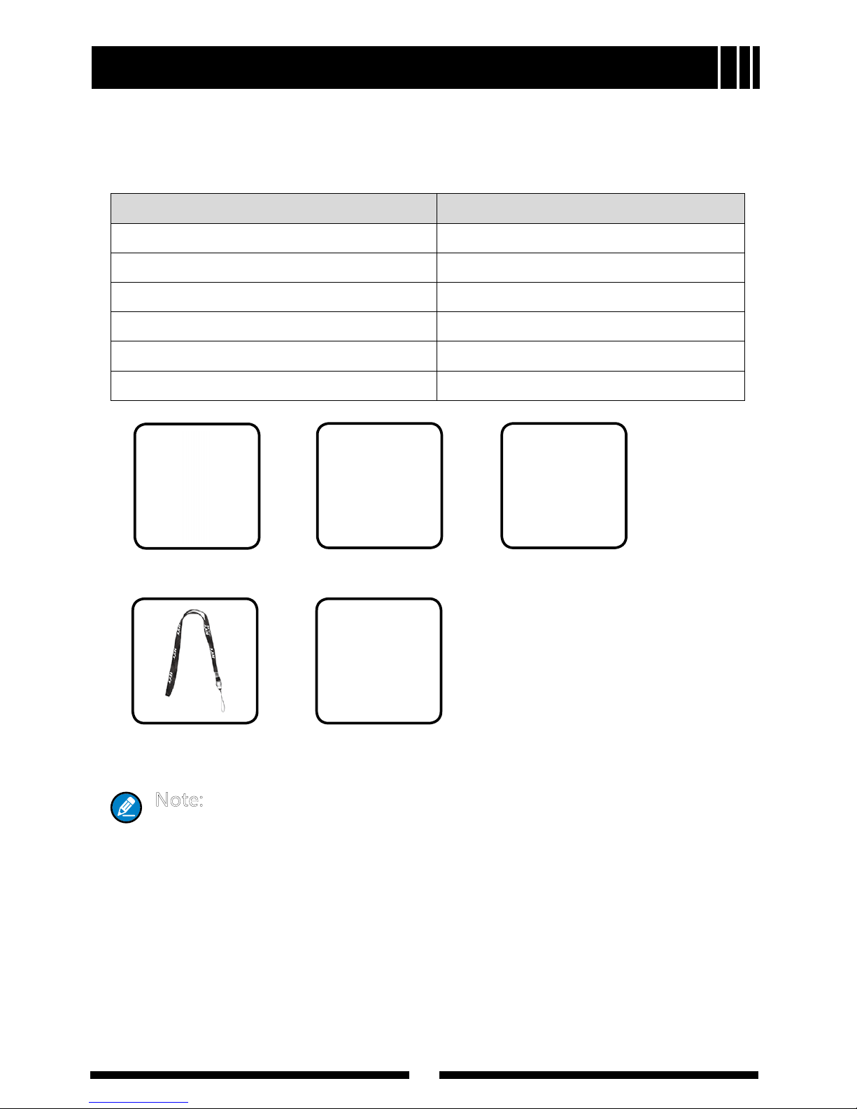
Product Inspection
Please unpack the package box carefully and check that all shipped items are
received; report any missing or damaged items to your reseller.
Accessories supplied with the radio
Item Qty. (PCS)
Antenna 1
Strap 1
Belt Clip 1
Li-Ion Battery 1
Switching Power 1
Owner’s Manual 1
Note: Frequency band is marked on the label of antenna; if not,
please refer to the label on the radio unit for frequency band
information.
Antenna Li-Ion Battery Switching Power
Strap Belt Clip
Page 8

4
Radio Overview
(1) Strap Hole (13) Charge Indicator
(2) Power On/Off Key (14) Speaker
(3) Antenna (15) Accessory Cover
(4) Volume Control Key [+] (16) Model Label
(5) PTT (Push-to-Talk) Key (17) Audio Accessory Jack
(6) Volume Control Key [-] (18) MINI USB Port
(7) Programmable Function Key (19) Screw for Belt Clip
(8) Microphone (20) Battery
(9) Channel Selector Knob (21) Belt Clip
(10) Channel Mark (22) Charging Piece
(11) Status Indicator (23) Battery Latch
(12) HYT Logo
Page 9

5
Radio Overview
﹡PTT (Push-to-Talk) Key
Press and hold down the PTT key to transmit, and release it to receive.
﹡LED Indicator
Status indications and alert tones are shown in the table below:
Power On (to enter
User Mode)
When the radio is turned on, an alert tone sounds and
the Status Indicator ashes orange once.
When the radio is currently on a blank channel, it
sounds beep tones continuously.
Power Off
When the radio is turned off, the power-off alert tone is
heard.
Low Battery Alert
The Status Indicator ashes red, and a low-pitched tone
sounds at an interval of 10 seconds.
Transmitting
The Status Indicator glows red.
When TOT timer expires, the radio sounds beep tones
continuously.
A TOT pre-alert tone sounds before the TOT timer
expires.
Receiving
The Status Indicator glows green when carrier is
present.
Scanning
The Status Indicator flashes green once per second,
while scanning is in process.
Scan Start Alert (programmable via CPS software with
programming cable): one beep is heard.
When signals are received on a certain channel, the
Status Indicator solidly glows green.
Scan End Alert (programmable via CPS software with
programming cable): one beep is heard.
VOX
One beep sounds when the feature is enabled.
Two beeps sound when the feature is disabled.
Compandor
Scrambler
Channel Lock
﹡Battery Latch
Used to secure or remove the battery.
﹡Audio Accessory Jack
Used to connect audio accessories.
Page 10
6
Radio Overview
﹡Mini USB Port
Used to connect accessories such as programming cable, cloning cable and
switching power.
Battery Information
Initial Use
New batteries from the factory are not fully charged, so be sure to charge a
new battery for at least 5 hours before initial use. Three full charge-discharge
cycles would optimize the capacity and performance of your battery. When
battery power runs low, it is time to recharge or to replace the battery.
Applicable Battery Packs
Please only use the battery specied by Hytera. Other batteries may burst,
causing bodily injury and property damage.
Caution:
1. Do not dispose of the battery in fire!
2. Recycling and disposal of the battery shall comply with your local
regulations.
3. Never attempt to dismantle the battery.
Note:
1.Chargethebatteryatatemperatureamong5℃ -40℃ .Violation
of the said limit may cause battery leakage or even damage.
2. When charging the battery that is attached to a radio, turn the
radio off to ensure a full charge.
3. Never charge a wet battery or a wet radio with battery attached.
Please dry it with a soft cloth prior to charge.
4.The battery will eventually wear out. When the operating time
of a fully charged battery is noticeably shorter than its normal
performance, you need to buy a new one. Please replace it ASAP.
5. If the product shuts off automatically due to low battery, please
charge the battery soon, or the battery could suffer damage.
6. If you plan not to use the radio for a long time, please remove
the battery from it to avoid any unexpected damage.
Page 11

7
Battery Information
7. Do not charge fully charged batteries for an “extra boost”. This
action will significantly reduce battery life.
8. Do not insert the radio or battery into the charger when it
doesn’t need to be charged, because continuous charging will
shorten the battery life. Note: Never use a charger to hold the
radio.
To Prolong Battery Life
1. Battery performance will decrease greatly at a temperature below 0℃.
Therefore, a spare battery is necessary in cold weather. However, the
replaced battery that fails to function at a low temperature may work at
room temperature, so keep it in place for later use.
2. The dust on the battery contact may make the battery work or charge
abnormally. Please use a clean and dry cloth to wipe the contacts before
charging or attaching the battery to the radio.
Battery Storage
1. If you plan to store a battery for a long time, please fully charge it rst to
avoid battery damage due to over-discharge.
2. To avoid battery capacity reduction due to over-discharge, recharge a
battery after storing it for a certain period of time: 6 months for Li-Ion & Li-
polymer batteries.
3. Store your battery in a cool and dry environment at room temperature to
reduce self-discharge.
Charging the Battery
When the Status Indicator ashes red, and an alert tone sounds at intervals of
ten seconds indicating the battery power runs low, please charge the battery
immediately. Only use the charger specied by Hytera. The Charge Indicator
will indicate the charging progress.
Page 12

8
Battery Information
Please follow steps below to charge the radio with switching power:
1. Plug the AC connector of the switching power into an AC outlet socket.
2. Plug the Mini USB connector of the switching power into the Mini USB port
at one side of the radio unit.
3. Make sure that the battery is in good contact with the switching power. The
charging process begins when the Charge Indicator at one side of the radio
unit glows orange.
4. When charging is completed, the Charge Indicator glows green. Then you
may remove the radio.
Status Charge Indicator of the Radio
Charging Solidly glows orange
Fully charged Solidly glows green
Please follow steps below to charge the radio/battery with a desktop
charger:
Page 13

9
Battery Information
1. Plug the AC connector of the switching power into an AC outlet socket.
2. Plug the Mini USB connector of the switching power into the Mini USB port
on back of the desktop charger.
3. Place the radio with the battery attached, or the battery alone, into the
charger.
4. Make sure that the battery is in good contact with charging pieces of the
desktop charger. The charging process begins when the charger LED
glows orange.
5. When charging is completed, the charger LED glows green. Then you may
remove the radio or battery.
Status Charger LED
Charging Solidly glows orange
Fully charged Solidly glows green
You can also use Hytera Six-Unit Switching Power to charge up to six radios/
batteries simultaneously, as shown in Figure 1. Please refer to the Owner’s
Manual for Six-Unit Switching Power for detailed operation procedures.
Figure 1 Schematic Diagram of Six-Unit Charger
When multiple desktop chargers are used simultaneously, you may connect
the chargers in parallel to create a multi-unit charger.
Assembly Method: Slide the latch of a charger into the slot on the bottom of
another charger, as shown in Figure 2.
Page 14

10
Battery Information
Figure 2 Diagram of Multi-Unit Charger Assembly
Antenna Information
● Stubby antenna is durable and ideal for communication at low transmit
power.
● Communication range may vary with terrain and your operating conditions.
Rainy days or forest locations may narrow your communication range, so
please make full preparations in advance to avoid potential inconvenience.
Assembly and Disassembly
Attaching/Removing the Battery
Attaching the Battery
1. Press the belt clip (in direction of ①) to make its bottom up. Then push the
battery (in direction of ②) into the radio. See Figure 1.
Note: Make sure the battery tab is fully inserted into the radio’s
slot.
2. Press the battery bottom (in direction of ③) gently until a click is heard,
which indicates that the battery is properly attached to the radio. See
Figure 2.
Note: If the battery is loose or unsecured, please take it down and
attach it again.
Latch of Desktop Charger
Page 15

11
Assembly and Disassembly
Removing the Battery
1. Make sure the radio is powered off first. Press the belt clip down (in
direction of ①) to make its bottom up. Then lift the battery latch (in
direction of ②). See Figure 3.
2. When the battery bottom gets tilted, release the latch and remove the
battery (in direction of ③) as shown in Figure 4.
Attaching/Removing the Antenna
Attaching the Antenna
1. Align the threaded end of the antenna with the antenna connector located
on the radio’s top side.
2. And turn the antenna clockwise to fasten it. See Figure 5.
Removing the Antenna
Turn the antenna counter-clockwise until you can remove it.
Figure 1 Figure 2
Figure 3 Figure 4
Page 16

12
Assembly and Disassembly
Attaching/Removing the Belt Clip
Attaching the Belt Clip
Unfasten the two screws for belt clip by a screwdriver, then place the belt clip
on the radio and align its two holes with two threaded holes of the radio, and
secure the two screws again. See Figure 6.
Removing the Belt Clip
Use a screwdriver to loosen the screws and remove the belt clip.
Note: Please be careful to avoid missing of screws.
Attaching/Removing the External Earpiece/Mini USB Device
Attaching the External Earpiece
1. Loosen the strap (in direction of ①), and tie it to the strap hole (in direction
of ②).
2. Uncover the accessory jack cover (in direction of ③), and insert the
earpiece plug into the jack (in direction of ④).
3. Then rotate the other end of the strap into the connector of the earpiece
cable (in direction of ⑤).
Note: If you want to adjust the connector’s position, please
hold the connector and draw the cable to avoid cable damage (in
directionof⑥ ).
Figure 6Figure 5
Page 17

13
Assembly and Disassembly
Removing the External Earpiece
Take converse steps to remove the external earpiece.
Note: When the earpiece is not in use, make sure the accessory jack
is properly covered to prevent intrusion of dust.
Attaching the External Mini USB Device
Uncover (not remove) the Accessory Cover (in direction of ①), and insert the
Mini USB connector into the Mini USB port (in direction of ②). See Figure 8.
Removing the Mini USB Device
Pull the Mini USB connector out and remove it.
Note: When the Mini USB Device is not in use, make sure the
accessory jack is properly covered to prevent intrusion of dust.
Figure 7
Figure 8
Page 18

14
Basic Operations
Turning the Radio On/Off
Long press the Power On/Off Key until an alert tone is heard to turn the radio
on/off.
Adjusting the Volume
Press [+] to increase or [-] to decrease the volume level. During volume
adjustment, the radio will sound alert tones at your selected volume level.
Selecting a Channel
Rotate the Channel Selector Knob to align your desired channel number with
the Channel Mark.
Transmitting
Press and hold down the PTT key, and speak into the microphone at your
normal voice level. Hold the radio about 2.5 to 5 centimeters away from your
mouth.
Receiving
Release the PTT key to receive.
Typical Coverage Area
Ofce Space Multi-Level
Inside steel/concrete ofce space buildings Inside multi-level buildings
Up to 200,000 sq ft Up to 15 oors
Programmable Auxiliary Functions
Auxiliary functions to the programmable key (with long/short press) can be
programmed via programming cable and CPS software.
● None
● Monitor
● Monitor Momentary
● Scan
● Scrambler
● Voice-operated Transmit (VOX)
● Compandor
● Squelch Off
Page 19

15
Programmable Auxiliary Functions
● Squelch Off Momentary
● Battery Strength
● Channel Lock (When this function is enabled, your current operating
channel will remain unchanged even if you rotate the Channel Selector
Knob. And this feature always remains valid after PC programming.)
Advanced Operations
The following functions can be programmed via programming cable and CPS
software. Contact your retailer for additional information.
CTCSS/CDCSS
You may set up talkgroups with unique CDCSS/CTCSS to prevent unwanted
conversations at the same frequency. If CTCSS/CDCSS is set on the current
channel, CTCSS/CDCSS match is required for the radio to unmute to an
incoming signal. If CTCSS/CCSS is not set, the radio can receive calls from all
users operating at the same frequency.
This feature does not mean that your conversation will not be heard by others.
Radios with the same CTCSS/CDCSS or with no CTCSS/CDCSS can also
receive calls from you.
Battery Save
This feature can reduce power consumption (enabled by your dealer).
If the radio is not operated (no key-press or knob-rotation) in Standby status,
it will automatically enter Battery Save mode upon expiration of a preset time
(30 seconds by default via programming software). The radio may exit the
Battery Save mode and get activated once any key is pressed or any signal is
received.
Time-out Timer (TOT)
This feature can prevent users from transmitting on a channel for an extended
period of time, and protect the radio from damage caused by prolonged
transmission. If the preset time expires, the radio will automatically terminate
transmission and keep beeping until the PTT key is released.
A pre-alert function to warn you of the TOT expiration in advance can be
programmed via programming cable and CPS software.
Page 20

16
Advanced Operations
Battery Strength Indicator
When you intend to know the battery strength, press the programmed Battery
Strength Indication key to illuminate the Status Indicator and learn the battery
strength by different colors. To exit this function, release the key.
Status Indicator of different colors represents different battery strength levels.
Refer to the table below:
Battery Strength Status Indication
70% - 100% Solidly glows green.
50% - 70% Solidly glows orange.
30% - 50% Solidly glows red.
10% - 30%
There is no indication upon press of the programmed
Battery Strength Indication key. However, the
indicator keeps ashing red in operation status.
Less than 10%
There is no indication upon press of the programmed
Battery Strength Indication key. However, the
indicator keeps flashing red in standby status and
keeps sounding a low-pitched tone at an interval of 10
seconds. If you press PTT at this time, the radio will
sound an alarm sound to warn you of the transmission
inhibition.
Monitor
● Squelch Off
Purpose: In this mode, the speaker is unmuted in any condition so as to
receive any sound on the current channel. When audio signal is received on
the channel, audio will be heard. Otherwise, background noise will be heard.
Operation: Press the Squelch Off key to enter this mode, and press it again to
exit.
● Squelch Off Momentary
Purpose: Refer to Squelch Off.
Operation: Hold down the Squelch Off Momentary key to enter this mode,
and release the key to exit.
Page 21

17
Advanced Operations
● Monitor
Purpose: In this mode, the receiving party can receive incoming calls
regardless of CTCSS/CDCSS condition. If the carrier condition is not satised,
the receiving party will fail to receive any incoming calls.
Operation: Press the Monitor key to enter this mode, and press it again to
exit.
● Monitor Momentary
Purpose: Refer to Monitor.
Operation: Hold down the Monitor Momentary key continuously to enter this
mode, and release the key to exit.
Scan
The Scan feature enables a two-way radio to continuously scan each channel
for activity. Press the key programmed as Scan, scan starts from the current
channel and ascends through the channel numbers in scan list. The Status
Indicator flashes green during scanning. When signals are received on a
certain channel with signaling matches, the Status Indicator solidly glows
green. To exit Scan mode, press this key again.
When Scan feature is activated, the radio begins continuous scanning for
activity on channels that can be scanned. If any activity is detected, the radio
will switch the channel to receive the call (the channel that can be scanned are
programmed by your dealer).
No Priority Channel
Suppose there is a scan list of 6 channels and all channels are non-prioritized,
the normal scan operation may proceed in the following sequence, as shown
in Figure 1.
Priority Channel Scan
Suppose there is a scan list of 5 channels and Channel 2 is prioritized as
Priority 1, the scan operation may proceed in the following sequence, as
shown in Figure 2.
Page 22

18
Advanced Operations
Figure 1 Normal Scan Sequence Figure 2 Priority Scan Sequence
● Scan On/Off
You can enter Scan mode through any of the following two methods:
Key-operated Entry
Press the programmed Scan key to enter Scan mode, provided that there are
no less than 2 channels in the scan list. Press the Scan key again or power
the radio off to exit this mode.
Auto Entry
If Auto Scan is enabled on a channel, the radio will automatically enter Scan
mode when it switches to this channel. When it switches to other channels or
is powered off, the radio will exit from Scan mode.
● Talk Back
This option defines whether users can talk back on the channel where
scanning pauses.
Checked: When the radio is staying on a scanned channel, it transmits on
the scanned channel; when the radio is not staying on a scanned channel, it
transmits on a preset channel.
Unchecked: The radio transmits on the preset channel.
● Priority Scan
This function enables users to scan the most frequently used channel so that
messages will not be missed. The priority channels are programmed by your
dealer via programming software. Please contact your local dealer for more
information.
Page 23

19
Advanced Operations
Note:Eventhoughtheradiostaysonanon-prioritychannel,
activities on the priority channel are still under detection. The radio
will switch to the priority channel once any activity is detected.
● Available Keys in Scan Mode
PTT key, Volume Control Key [+]/[-], Squelch Off key, Squelch Off
Momentary key, Monitor and Monitor Momentary keys.
Busy Channel Lockout (BCL)
This function can help avoid interference between radios operating on the
same channel. When the channel is already in use, the radio will sound a
continuous warning tone and return to Receive mode upon PTT press. To
cancel the tone, release the PTT key.
Low Battery Alert
When battery power runs low, the Status Indicator flashes red and a low-
pitched tone will sound at an interval of ten seconds to remind users to replace
or charge the battery.
Voice-Operated Transmit (VOX)
With the dedicated VOX earpiece, you can enjoy hands-free communication.
After this function is enabled, the radio will automatically begin transmitting
when you speak, and terminate transmitting when you stop talking, with no
need of PTT press.
Operation Steps:
1. Push the PTT/VOX switch on the earpiece to VOX.
2. Plug the earpiece into the accessory jack of the radio.
3. Press the programmed VOX key to activate the VOX feature.
4. Speak through the microphone on the earpiece to transmit your voice.
Operation Instructions:
1. Press the PTT key on you radio to disable the VOX during its operation,
and release the key to reactivate this function.
2. Press the programmed VOX key to enable/disable the VOX feature, with
corresponding alert tone. When it is enabled, the alert tone sounds once;
when it is disabled, the alert tone sounds twice.
3. The VOX feature will be disabled automatically after the radio is turned off
or programmed.
Page 24

20
Advanced Operations
4. The VOX function will work with a dedicated earpiece.
5. You dealer may set VOX sensitivity or disable the VOX feature through the
programming software. The VOX key will be null once the VOX feature is
disabled.
Compandor
With this feature, you can communicate with clear voice in despite of various
noises. It can be enabled/disabled through the programmed key, or set on a
denite channel via programming cable and CPS software. When this function
is enabled, one beep sounds; when it is disabled, two beeps sound.
Scrambler
This technology can encrypt audio signals, and provide real security for
privacy between communication parties. It can enable/disable through the
programmed keys, or set on a denite channel via programming cable and
CPS software. When this function is enabled, one beep sounds; when it is
disabled, two beeps sound.
Note:
1.IfyouintendtoswitchbetweenVOXandPTTfunctions,unplug
theearpiece,toggletheswitchtoVOXorPTTandplugthe
earpiece again.
2. After the above operations are completed, the radio takes
approximately 2-3secondstoperformauto-detectionuntilit
operates normally. During the detection process, do not handle
the earpiece; otherwise, it may malfunction due to detection
errors.
3. If the earpiece functions abnormally, please pull and plug it
again as instructed above.
4.YoumayselectVOXlevelsaccordingtotheoperating
environment.ToomuchnoiseandtoohighVOXlevelmaycause
the radio to transmit continuously.
5.Useonlythe VOXearpiece specifiedbyHytera, andproperly
plugitintothejack;otherwise,theVOXfunctionmaynotwork.
Page 25

21
Troubleshooting
Symptom Solution
Cannot power on the radio.
● The battery may have run out. Please
recharge the battery or replace it with a
new one.
● The battery may have been improperly
installed. Please remove the battery and
insert it again.
The fully charged battery runs
down quickly.
● The battery may have worn out. Please
replace it ASAP.
● The battery is not fully charged. Make
sure the battery is removed only after
the Charge Indicator of the radio or the
charger LED glows green.
Cannot communicate with
group members.
● Make sure you are on the same channel
- check whether the Channel Lock
function is enabled and you are operating
on an undesired channel. When this
function is enabled, your current
operating channel will remain unchanged
even if you rotate the Channel Selector
Knob.
● Make sure that radios in your group use
the same CTCSS/CDCSS signaling and
operate on the same channel.
● Group members may be too far away
from each other. Please make sure that
you are within the communication range.
Hear non-group members.
● The CTCSS/CDCSS settings should be
changed for all radios in your group via
programming cable and CPS software.
No voice or low voice received
from the transmitting party.
● Please ensure an adequate volume level
is selected.
● Or please send the radio to your retailer
for microphone examination.
Noises always on.
● In Monitor mode, group members may
have been too far away from each other.
Please move within the communication
range and then re-power the radio on.
● Please confirm whether there is strong
interference near the radio.
Page 26

22
Care and Cleaning
● Do not hold the radio by its antenna or external earpiece directly.
● Do not place the radio in a dusty or dirty environment.
● Clean the radio with a lint-free cloth to remove dirt or grease, to avoid poor
contact due to excessive dust.
● Clean the radio using a lint-free cloth moistened with clean water and a
mild dishwashing liquid.
● Avoid subjecting the radio to corrosives, solvents or spirits.
Optional Accessories
Note: Pictures above are for reference only and may vary from
actualproduct.However,featuringfunctionsshallbeheld.
The above items are the main optional accessories of this radio,
and please contact your retailer for more other accessories.
Earset with in-line
MIC EHS12
Earset with In-Line
MIC & VOX EHS09
Six-unit Switching
Power PS4001
Belt Clip BC16
Programming Cable (USB
to Serial Port) PC30
Rapid-Rate Charger
(for Li-Ion Battery) CH06L01
Carrying Case
HY1010-3BP
Page 27

23
Default Frequency List
Channel Table No. Frequency (MHz) Code (Hz)
1 2 464.5500 67.0
2 8 467.9250 67.0
3 9 461.0375 67.0
4 10 461.0625 67.0
5 11 461.0875 67.0
6 12 461.1125 67.0
7 13 461.1375 67.0
8 14 461.1625 67.0
9 1 464.5000 67.0
10 3 467.7625 67.0
11 4 467.8125 67.0
12 5 467.8500 67.0
13 6 467.8750 67.0
14 7 467.9000 67.0
15 15 461.1875 67.0
16 16 461.2125 67.0
Frequency and Codes Chart
If the default frequencies are not adequate for communication needs, you can
re-program your device using the following optional business frequencies via a
Customer Programming Cable and Software.
Contact your point of purchase for additional re-programming information.
Table No. Frequency (MHz) Table No. Frequency (MHz)
1 464.5000 46 466.3375
2 464.5500 47 466.3625
3 467.7625 48 467.7875
4 467.8125 49 467.8375
5 467.8500 50 467.8625
6 467.8750 51 467.8875
7 467.9000 52 467.9125
8 467.9250 53 469.4875
9 461.0375 54 469.5125
10 461.0625 55 469.5375
Page 28

24
Table No. Frequency (MHz) Table No. Frequency (MHz)
11 461.0875 56 469.5625
12 461.1125 57 462.1875
13 461.1375 58 462.4625
14 461.1625 59 462.4875
15 461.1875 60 462.5125
16 461.2125 61 467.1875
17 461.2375 62 467.4625
18 461.2625 63 467.4875
19 461.2875 64 467.5125
20 461.3125 65 451.1875
21 461.3375 66 451.2375
22 461.3625 67 451.2875
23 462.7625 68 451.3375
24 462.7875 69 451.4375
25 462.8125 70 451.5375
26 462.8375 71 451.6375
27 462.8625 72 452.3125
28 462.8875 73 452.5375
29 462.9125 74 452.4125
30 464.4875 75 452.5125
31 464.5125 76 452.7625
32 464.5375 77 452.8625
33 464.5625 78 456.1875
34 466.0375 79 456.2375
35 466.0625 80 456.2875
36 466.0875 81 468.2125
37 466.1125 82 468.2625
38 466.1375 83 468.3125
39 466.1625 84 468.3625
40 466.1875 85 468.4125
41 466.2125 86 468.4625
42 466.2375 87 468.5125
43 466.2625 88 468.5625
44 466.2875 89 468.6125
45 466.3125 90 468.6625
Frequency and Codes Chart
Page 29

25
CTCSS AND CDCSS CODES
CTCSS Codes
CTCSS Hz CTCSS Hz
1 67.0 21 131.8
2 69.3 22 136.5
3 71.9 23 141.3
4 74.4 24 146.2
5 77.0 25 151.4
6 79.7 26 156.7
7 82.5 27 162.2
8 85.4 28 167.9
9 88.5 29 173.8
10 91.5 30 179.9
11 94.8 31 186.2
12 97.4 32 192.8
13 100.0 33 203.5
14 103.5 34 210.7
15 107.2 35 218.1
16 110.9 36 225.7
17 114.8 37 233.6
18 118.8 38 241.8
19 123.0 39 250.3
20 127.3
CDCSS Codes
CDCSS Hz CDCSS Hz CDCSS Hz
1 23 37 223 73 446
2 25 38 225 74 452
3 26 39 226 75 454
4 31 40 243 76 455
5 32 41 244 77 462
6 36 42 245 78 464
7 43 43 246 79 465
8 47 44 251 80 466
9 50 45 252 81 503
10 51 46 255 82 506
11 53 47 261 83 516
12 54 48 263 84 523
Page 30

26
CDCSS Hz CDCSS Hz CDCSS Hz
13 65 49 265 85 526
14 71 50 266 86 532
15 72 51 271 87 546
16 73 52 274 88 565
17 74 53 306 89 606
18 114 54 311 90 612
19 115 55 315 91 624
20 116 56 325 92 627
21 122 57 331 93 631
22 125 58 332 94 632
23 131 59 343 95 645
24 132 60 346 96 654
25 134 61 351 97 662
26 143 62 356 98 664
27 145 63 364 99 703
28 152 64 365 100 712
29 155 65 371 101 723
30 156 66 411 102 731
31 162 67 412 103 732
32 165 68 413 104 734
33 172 69 423 105 743
34 174 70 431 106 754
35 205 71 432
36 212 72 445
Hytera offers free download CPS software to modify/congure OBR radios per
user specic requirements. The software is available on www.hytera.us.
CTCSS AND CDCSS CODES
Page 31

27
Default Factory Feature List
Key Default Feature Note
SK1 (Short Press) Monitor
Please refer to Monitor for detailed
feature description.
SK1 (Long Press) Scan
Please refer to Scan for detailed
feature description.
﹡Programmable Function Key
The side key can be programmed with long/short press functions via
Programming Cable and CPS Software.
Note: Short Press means key press shorter than 1 second, while
Long Press means key press longer than 1 second.
Hytera’s Limited Warranty for the United States and Canada
HYTERA AMERICA, INC. warrants its manufactured Communication Products
against defects in material and workman-ship under normal use and service
for a period of time from the date of purchase by end-user as scheduled below:
HYT Brand: TC-310 - OBR One (1) year
Warranty Exclusions:
Defects or damage resulting from use of the Product other than its normal
and customary manner. Defects or damage from misuse, accident, water, or
neglect Defects or damage from improper testing, operation, maintenance,
installation, alteration, modification, or adjustment. Breakage or damage
to antennas unless caused directly by defects in material workmanship
of HYTERA AMERICA, INC. or its direct affiliates. A Product subjected to
unauthorized Product modifications, disassembles, or repairs (including,
without limitation, the addition to the Product of non-HYTERA AMERICA,
INC. supplied equipment) which adversely affect performance of the Product
or Interfere with HYTERA AMERICA, INC.’s normal warranty inspection and
testing of the Product to verify any warranty claim. A Product which has had
the serial number removed or made illegible is not covered by this Warranty
either. A Product which, due to illegal or unauthorized alteration of the software/
firmware in the Product, does not function in accordance with HYTERA
AMERICA, INC.’s published specifications or the FCC type acceptance
Page 32

28
labeling in effect for the Product at the time the Product was initially distributed
from HYTERA AMERICA, INC.
Rechargeable batteries are likewise not covered by this Warranty if:
i) Any of the seals on the battery enclosure of cells are broken or show
evidence of tampering.
ii) The damage or defect is caused by charging or using the battery in
equipment or service other than the Product for which it is specied. Freight
costs to the repair depot.
iii) Unapproved upgrades or modications.
Who’s Covered
This warranty is not transferable and it only extends to the first consumer
purchaser.
For Warranty Service or any additional information please contact your Hytera
/ HYT point of purchase.
Hytera’s Limited Warranty for the United States and Canada
Page 33

C10524 L06774
8110031 000200
2015
Hytera Communications Corporation Limited.
Hytera Communications Corporation Limited.
 Loading...