

Hyster S40XM, S45XM, S50XM, S60XM, S65XM Operating Manual
...
OPERATING MANUAL
CHALLENGER
H45XM,H50XM,H55XM,H60XM,H65XM
SPACESAVER
S40XM, S45XM, S50XM, S55XM, S55XMS, S60XM,
S65XM
DO NOT REMOVE THIS MANUAL FROM THIS UNIT
Property of American Airlines
HYSTER COMP ANY
P ART NO. 1458874

LIFT TRUCK MODEL SERIAL NUMBER
ENGINE MODEL SERIAL NUMBER
TRANSMISSION TYPE SERIAL NUMBER
MAST LIFT HEIGHT GROUP NUMBER
CARRIAGE TYPE GROUP NUMBER
DRIVE TIRE SIZE STEERING TIRE SIZE
SPECIAL EQUIPMENT OR ATTACHMENTS
REGISTERED TRADEMARKS
Hyster,
Hyster Company.
, Challenger, SpaceSaver, Monotrol, RACKLOADER, SitDrive and StanDrive are trademarks of
Property of American Airlines

FOREWORD
FOREWORD
To OWNERS, USERS, and OPERATORS:
The safe and efficient operation of a lift truck requires
skill and alertness on the part of the operator. To develop
the skill required the operator must:
• Receive training in the proper operation of THIS lift
truck.
• Understand the capabilities and limitations of the lift
truck.
• Become familiar with the construction of the lift truck
and see that it is maintained in good condition.
• Read and understand the warnings and operating
procedures in this manual.
In addition, a qualified person, experienced inlift truck operation,mustguidea newoperatorthroughseveral drivingand
load handling operations before the new operator attempts
to operate the lift truck alone.
HYSTER COMPANY 2003
It is the responsibility of the employer to make sure that
the operator can see, hear, and has the physical and
mental ability to operate the equipment safely.
Various laws and regulations require the employer to train
lift truck operators. These laws and regulations include:
• Occupational Safety and Health Act (USA)
• Canada Material Handling Regulations
NOTE: A comprehensive operator trainingprogram isavailable from HYSTER COMPANY. For further details, contact
your dealer for Hyster lift trucks.
This OPERATING MANUAL contains information necessary for the operation and maintenance of a basic fork lift
truck. Optional equipment is sometimes installed that can
change some operating characteristics described in this
manual. Make sure the necessary instructions are available and understood before operating the lift truck.
1
Property of American Airlines
FOREWORD
Some of the components and systems described in this
OPERATING MANUAL will NOT be installed on your unit.
If you have a question about any item described, contact
your dealer for Hyster lift trucks.
Additional information that describes the safe operation
and use of lift trucks is available from the following
sources:
• Employment safety and health standards or
regulations (Examples: “Occupational Safety and
Health Standards (USA)”, “Canada Material Handling
Regulations”.
• Safety codes and standards (Example: American
National Standard, ANSI B56.1, Safety Standard For
Low Lift And High Lift Trucks.
• Publications from government safety agencies,
government insurers, private insurers and private
organizations (Example: Accident Prevention Manual
For Industrial Operations, from the National Safety
Council).
• Guide for Users of Industrial Lift Trucks (Hyster Part
No. 852930) describes lift truck safety, good
maintenance practices, and training programs and is
available from your dealer for Hyster lift trucks.
NOTE: Hyster lift trucks are not intended for use on public
roads.
NOTE: The following symbols and words indicate safety information in this manual:
WARNING
Indicates a condition that can cause death or injury!
CAUTION
Indicatesa condition that can causeinjury or property
damage!
2
Property of American Airlines

CONTENTS
CONTENTS
FOREWORD 1..................................
To OWNERS, USERS, and OPERATORS 1......
CONTENTS 3...................................
MODEL DESCRIPTION 11.........................
GENERAL 1 1..................................
OPERATOR PROTECTION EQUIPMENT 11......
NAMEPLATE 12...............................
SAFETY LABELS 13...........................
INSTRUMENTS AND CONTROLS 17............
OPERATING PROCEDURES 33....................
GENERAL 33..................................
Know Your Lift Truck 33......................
Stability And Center Of Gravity 35.............
Capacity (Weight And Load Center) 36.........
INSPECTION BEFORE OPERATION 37..........
Checks With The Engine Stopped 37..........
Starting Procedures 38.......................
Starting Procedures, Gasoline Or LPG
Engine 38..................................
Starting Procedures, Diesel Engine 38.........
Checks With The Engine Running 39..........
OPERATING TECHNIQUES 40..................
Basic Operating Procedures 41...............
Driving And Direction Changes 42.............
Inching 43..................................
Steering (Turning) 44........................
Load Handling, General 46...................
Load Handling, Lifting, Lowering And
Tilting 47...................................
Load Handling, How To Engage And Disengage
A Load 49..................................
Load Handling, Travelling 52..................
HIGHWAY TRUCKS, RAIL CARS AND
DOCKS 56....................................
ATTACHMENTS 58............................
STOPPING 58.................................
PARKING 58..................................
MAINTENANCE 61...............................
GENERAL 61..................................
Serial Number Data 62.......................
HOW TO MOVE A DISABLED LIFT TRUCK 62....
HowToTowtheLiftTruck 62..................
HOW TO PUT A LIFT TRUCK ON BLOCKS 63....
How To Raise the Drive Tires 63..............
3
Property of American Airlines
CONTENTS
How To Raise the Steering Tires 64...........
MAINTENANCE SCHEDULE 67...................
MAINTENANCE PROCEDURES EVERY 8 HOURS
OR DAILY 81.....................................
HOW TO MAKE CHECKS WITH THE ENGINE
STOPPED 81..................................
Tires and Wheels 81........................
Forks 83...................................
Forks, Adjustment 83........................
Forks, Removal 83..........................
Forks, Installation 85.........................
Inspection Of Forks, Mast, and Lift Chains 85...
Safety Labels 87............................
Operator Restraint System 87................
Steering Column Latch 89....................
Check For Fuel, Oil Or Coolant Leaks 89.......
Drive Belt 89...............................
Engine Oil 89...............................
Transmission Oil Temperature 92.............
Hydraulic System Oil 93.....................
Battery 94.................................
Air Filter 94................................
HOW TO MAKE CHECKS WITH THE ENGINE
RUNNING 95..................................
Gauges, Lights, Horn, Fuses and Relays 98....
“Check Engine” Light(Mazda and GM3.0L LPG
Closed--Loop With Emission System) 98........
“Check Engine” Light
(GM 3.0 Liter Gasoline) 98....................
Engine Oil Pressure 98.......................
Cooling System 99..........................
Steering System 99..........................
Service Brakes 99...........................
Parking Brake 100............................
Fuel System 101.............................
Water Separator, Diesel Engine 101.............
Fuel Filter, Diesel Engine 102..................
Remove Air From The Diesel Fuel System 102...
Control Levers and Pedals 102.................
Lift System Operation 102.....................
Cooling System 103..........................
HOW TO ADD FUEL TO THE LIFT TRUCK 104....
Liquefied Petroleum Gas (LPG) 105.............
Gasoline or Diesel Fuel 108....................
4
Property of American Airlines
CONTENTS
WHEELS AND TIRES 108.......................
General 108.................................
How To Change A Solid Rubber Tire
S40--65XM Models 109.......................
RemoveAndInstallTheTireOnThe
Wheel 109...................................
How To Repair A Pneumatic Tire H45--65XM
Models 1 11..................................
Remove The Wheels From The Lift Truck 111....
Remove The Wheel From The Tire 112..........
Install The Wheel in the Tire 1 15................
AddAirToTheTires 117......................
Install the Wheels 118.........................
INSTALLATION PROCEDURES, DUAL DRIVE
WHEELS 119...................................
SOLID RUBBER TIRES 119......................
Remove The Tire From The Wheel 120..........
Install The Tire On The Wheel 120..............
OPERATING PROCEDURES FOR A NEW OR
REBUILT ENGINE 123...........................
CHANGES TO THE OVERHEAD GUARD 123......
HOW TO PUT INTERNAL COMBUSTION
ENGINE (I.C.E.) TRUCKS IN STORAGE 123.......
HOW TO PUT BATTERIES IN STORAGE 124......
HOW TO STORE A LIFT TRUCK 125.............
HOW TO MOVE A LIFT TRUCK ON A
TRANSPORT 127...............................
Loading 127.................................
Unloading 128...............................
PREPARATION FOR USE 129....................
Preparation After Transport 129................
Preparation After Storage 129..................
5
Property of American Airlines
CONTENTS
NOTES
6
Property of American Airlines
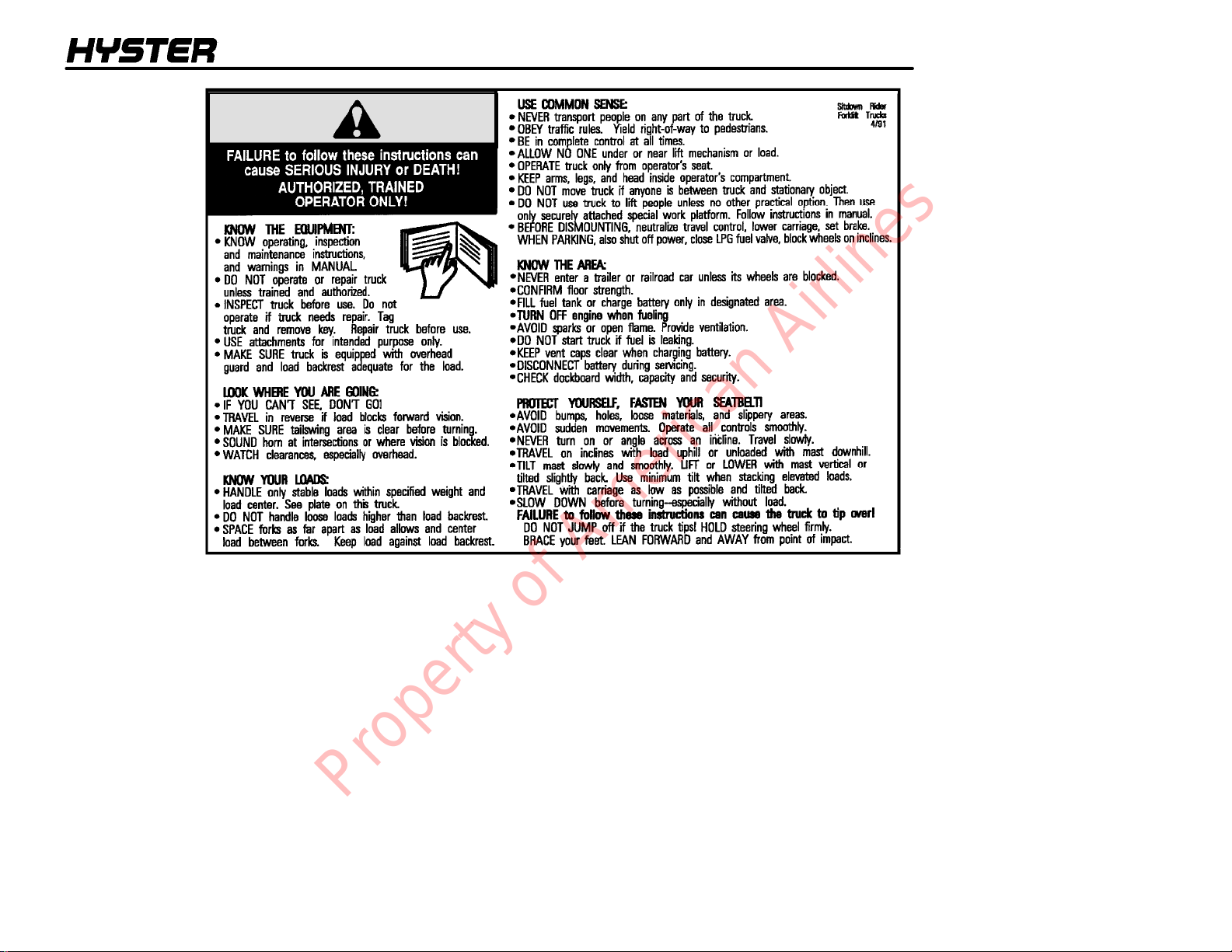
A WARNING
label with this
information
must be on the
lift truck.
WARNING
7
Property of American Airlines
WARNING
NOTES
8
Property of American Airlines
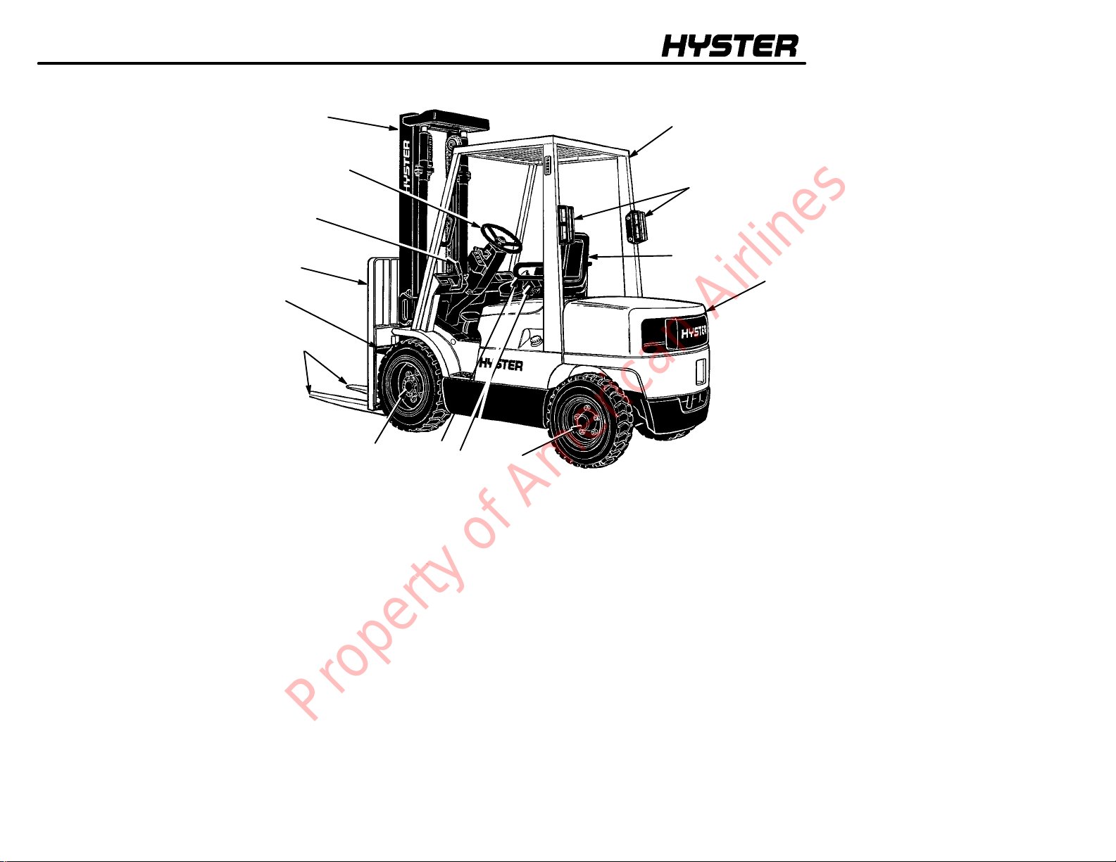
MODEL DESCRIPTION
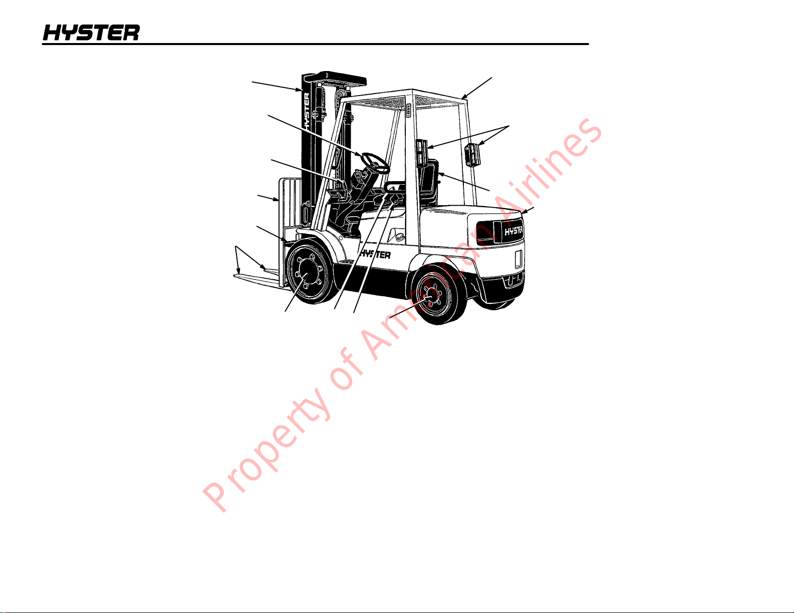
1. OVERHEAD GUARD
2. TAIL LIGHT, BRAKE
LIGHT, REVERSE LIGHT
3. SEAT
4. COUNTERWEIGHT
5. STEERING AXLE
6. SEAT BELT AND
HIP RESTRAINT
7. DRIVE AXLE
8. FORKS
9. CARRIAGE
10. LOAD BACKREST
EXTENSION
11. PARKING BRAKE
12. STEERING WHEEL
13. MAST
FIGURE 1. MODEL VIEW SHOWING MAJOR COMPONENTS OF S40--65XM SERIES
13
12
11
10
9
8
7
6
6
5
1
2
3
4
12779
9
Property of American Airlines
MODEL DESCRIPTION
1. OVERHEAD GUARD
2. TAIL LIGHT, BRAKE
LIGHT, REVERSE LIGHT
3. SEAT
4. COUNTERWEIGHT
5. STEERING AXLE
6. SEAT BELT AND
HIP RESTRAINT
7. DRIVE AXLE
8. FORKS
9. CARRIAGE
10. LOAD BACKREST
EXTENSION
11. PARKING BRAKE
12. STEERING WHEEL
13. MAST
FIGURE 2. MODEL VIEW SHOWING MAJOR COMPONENTS OF H45--65XM SERIES
13
12
11
10
9
8
7
6
6
5
1
2
3
4
12626
10
Property of American Airlines

MODEL DESCRIPTION
MODEL DESCRIPTION
GENERAL
This OPERATING MANUAL is for the following models of
lift trucks:
S45XM, S45XM, S50XM, S55XM, S55XMS,
S60XM, S65XMS
H40XM, H50XM, H55XM, H60XM, H65XM
These lift trucks are available with the following engines:
• Mazda M4--2.0G or M4--2.2G engine which use
gasoline or LPG fuel
• GM 3.0L engine that uses gasoline or LPG fuel
• Perkins 704--26 (UB) diesel engine
H45--65XM only
The single--speed powershift transmission can be
equipped with two types of controls:
• A MONOTROLR pedal that controls both the for-
ward and reverse operation of the powershift transmission and the speed of the engine.
• A direction control lever on the left side of the
steering column that controls the forward, neutral
and reverse operation of the powershift transmission. A separate accelerator pedal controls the engine speed.
The S40--65XM lift trucks are equipped with solid rubber
tires. The H45--65XM lift trucks are equipped with pneumatic tires or solid rubber tires that look like pneumatic
tires. See Wheels And Tires in the MAINTENANCE
SECTION for a description of these tires.
OPERATOR PROTECTION EQUIPMENT
The LOAD BACKREST EXTENSION is installed to keep
loose parts of the load from falling back toward the operator. It must be high enough, with openings small enough
to prevent the parts of the load from falling backwards. If
a load backrest extension that is different from the one
installed on your lift truck is required, contact your Hyster
lift truck dealer.
The OVERHEAD GUARD is intended to offer reasonable
protection to the operator from falling objects, but can not
protect against every possible impact. Therefore, it must
11
Property of American Airlines
MODEL DESCRIPTION
not be considered a substitute for good judgment and
care when handling loads. Do not remove the overhead
guard.
The SEAT BELT AND HIP RESTRAINT provide additional
means to help the operator keep the head and torso substantially within the confines of the lift truck frame and
overhead guard if a tipover occurs. This restraint system
is intended to reduce the risk of the head and torso being
trapped between the lift truck and the ground, but it can
not protect the operator against all possible injury in a
tipover. The hip restraint will help the operator resist side
movement. It is not a substitute for the seat belt. Always
fasten the seat belt.
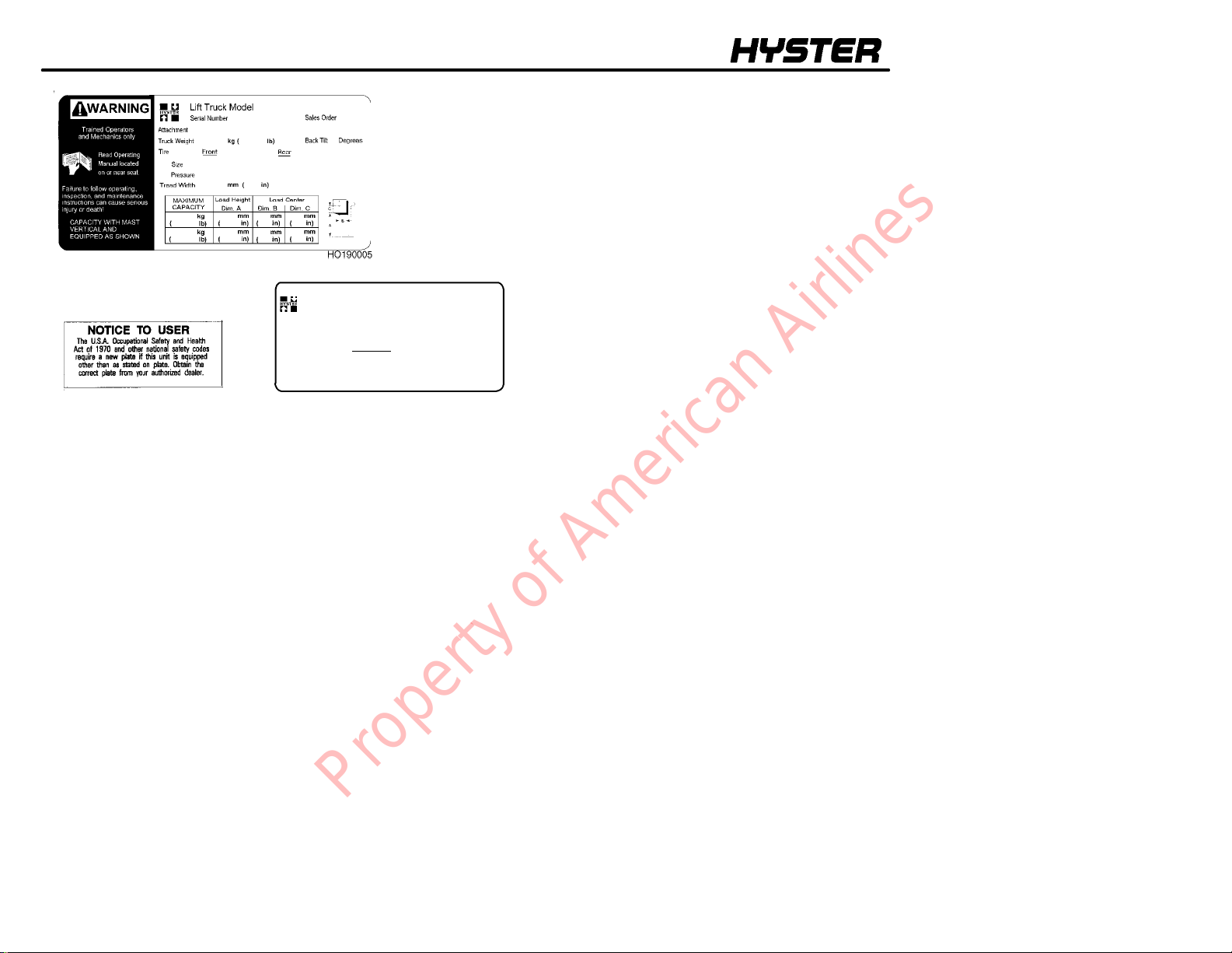
NAMEPLATE
WARNING
Any change to the lift truck, the tires or its equipment
can change the lifting capacity. If the Nameplate does
not show the maximum capacity , or if the lift truck
equipment, including the battery for electric trucks,
does not match that shown on the Nameplate, the lift
truck must not be operated.
The capacity is specified in kilograms (kg) and pounds
(lb). The capacity is the maximum load that the lift truck
can handle for the load condition shown on the Nameplate.
The maximum capacity for the lift truck, at full load height,
must be shown on the Nameplate. Special capacities
with the load height reduced or with optional load centers,
may also be shown on the Nameplate.
The lift truck serial number code is on the Nameplate. The
serial number code is also stamped on the lift truck frame
When a lift truck is shipped incomplete from the factory,
the Nameplate is covered by an INCOMPLETE label as
shown in FIGURE 3. If the equipment on the truck is
changed, the Nameplate is covered by a NOTICE label as
shown in FIGURE 3. If your lift truck has either of these
labels, do not operate the lift truck. Contact your dealer
for HYSTER lift trucks to obtain a complete correct Nameplate.
.
12
Property of American Airlines

MODEL DESCRIPTION
WARNING
DO NOT add to or modify the lift truck. Any change to
the lift truck, the tires or its equipment can change
the lifting capacity. The lift truck must be rated as
equipped and the nameplate must show the new capacity rating.
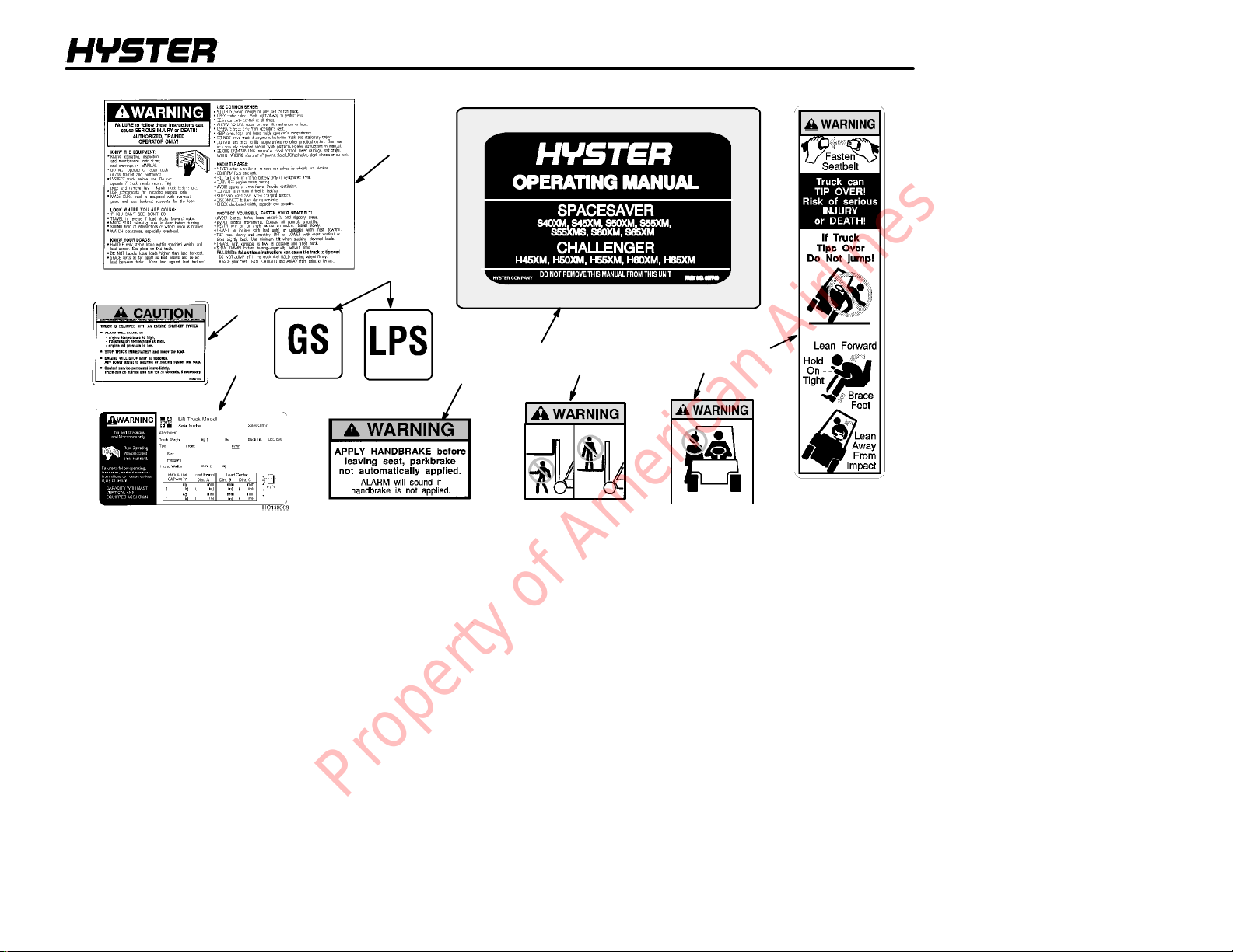
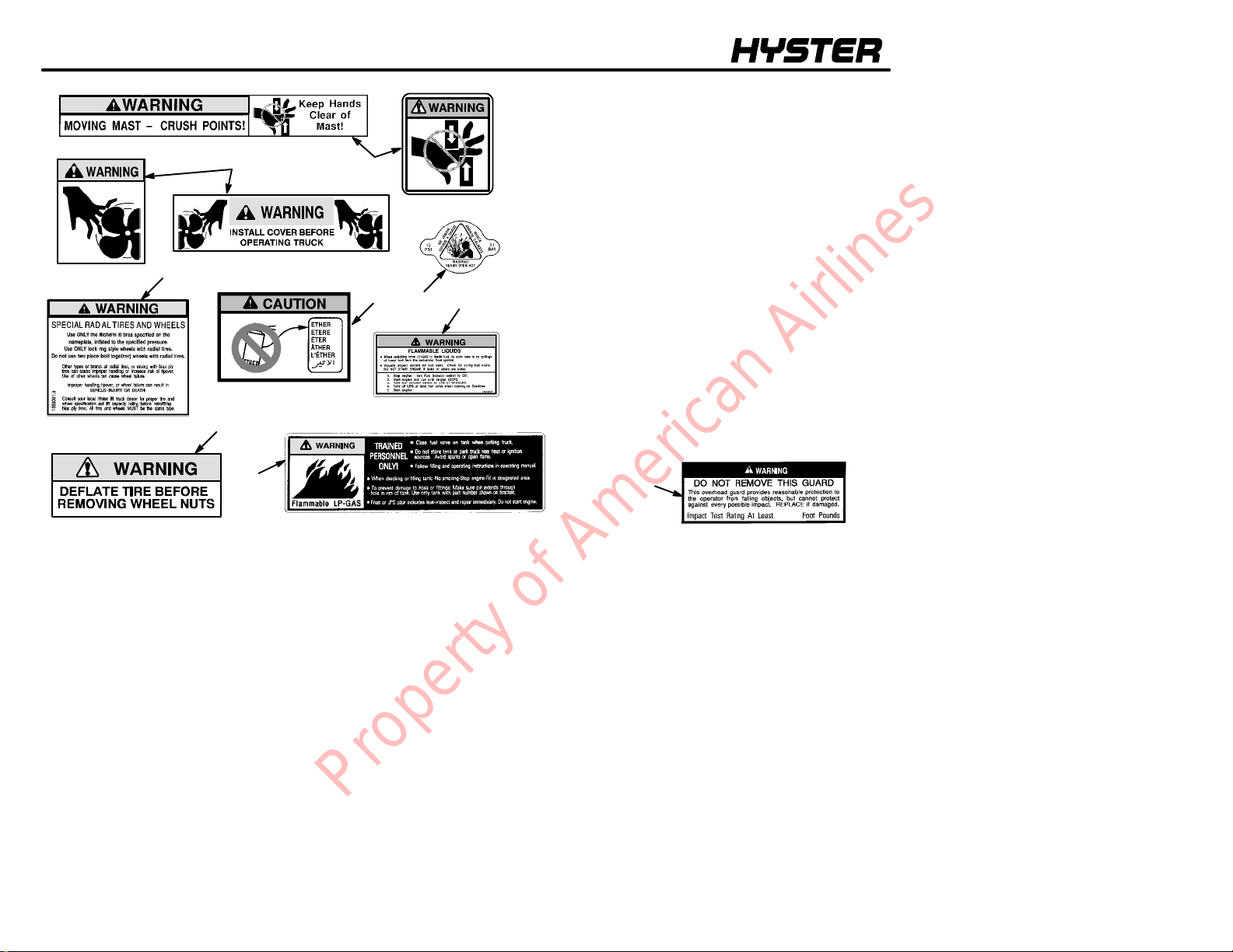
SAFETY LABELS
Safety labels are installed on the lift truck to give information about possible hazards. It is important that all safety
labels are installed on the lift truck and can be read. See
FIGURE 4.
13
Property of American Airlines
MODEL DESCRIPTION
NAMEPLATE
NOTICE LABEL
FIGURE 3. NAMEPLATE AND LABELS
TRUCK MODEL
Serial no.
Approx.weight
This unit was shipped incomplete from factory/
The U.S.A. Occupational Safety and Health Act of 1970 and other
national safety codes require the installation of a c ompleted Nameplate
showing unit configurationand ratedcapacity.Completed Nameplates
may be obtained through your HYSTER dealer.
NOTICE TO USER
1304058R
INCOMPLETE LABEL
14
Property of American Airlines
MODEL DESCRIPTION
1
3
2
5
SEE THE PARTS MANUAL FOR THE PART NUMBER AND LOCATION OF LABELS
FIGURE 4. WARNING AND SAFETY LABELS (1 of 2)
6
4
7
8
9
Property of American Airlines
15
MODEL DESCRIPTION
Y
)
11
12
16
10
13
14
15
1. WARNING, OPERATION
2. DRIVE TRAIN PROTECTION CAUTION
3. OPTIONAL FIRE SAFETY RATING
4. CASE WITH OPERATING MANUAL
5. NAMEPLATE
6. WARNING FOR PARKING BRAKE
7. NO ONE ON OR UNDER FORKS
8. NO RIDERS
9. TIPOVER WARNING
10. MAST WARNING
1 1. FAN WARNING
12. RADIAL TIRE WARNING--H45--65XM Only
13. ETHER WARNING--H45--65XM Only
14. RADIATOR CAP WARNING -- H45--65XM
Only
15. DUAL FUEL WARNING
16. TWO--PIECE WHEEL WARNING
H45--65XM Only
17. FLAMMABLE LP--GAS
18. GUARD LABEL
16
17
SEE THE PARTS MANUAL FOR THE PART NUMBER AND LOCATION OF LABELS
FIGURE 4. WARNING AND SAFET
LABELS(2of2
18
Property of American Airlines
MODEL DESCRIPTION
5
4
3
2
1
6
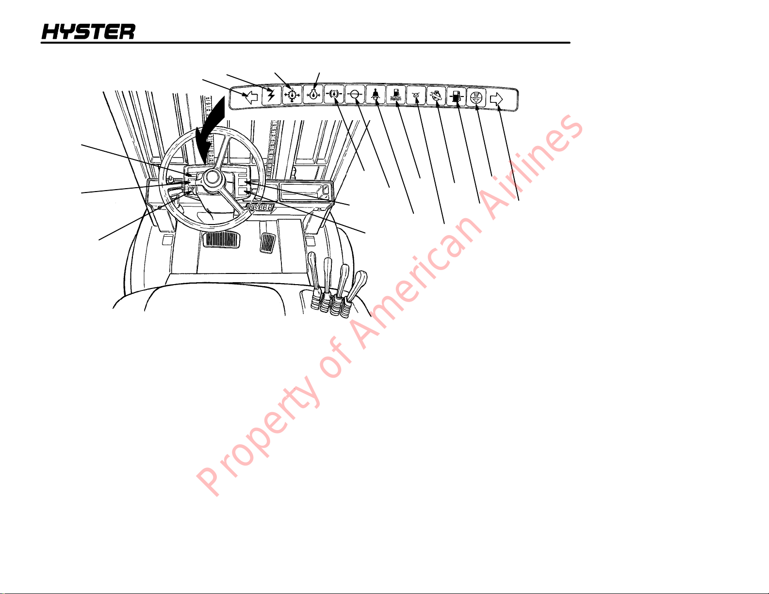
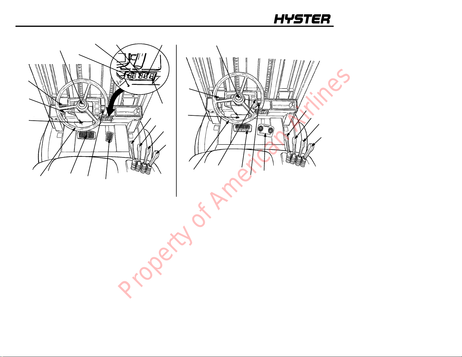
FIGURE 5. INSTRUMENTS
7
17
8
18
11
9*
10
*
USED ONLY ON S40--65XM
MODEL TRUCKS
13
12
14
15
16
17
Property of American Airlines
MODEL DESCRIPTION
INSTRUMENTS AND CONTROLS
WARNING
If any of the instruments, levers, or pedals do not operate as described in the following tables, report the problem immediately. DO NOT operate the lift truck until the problem is corrected.
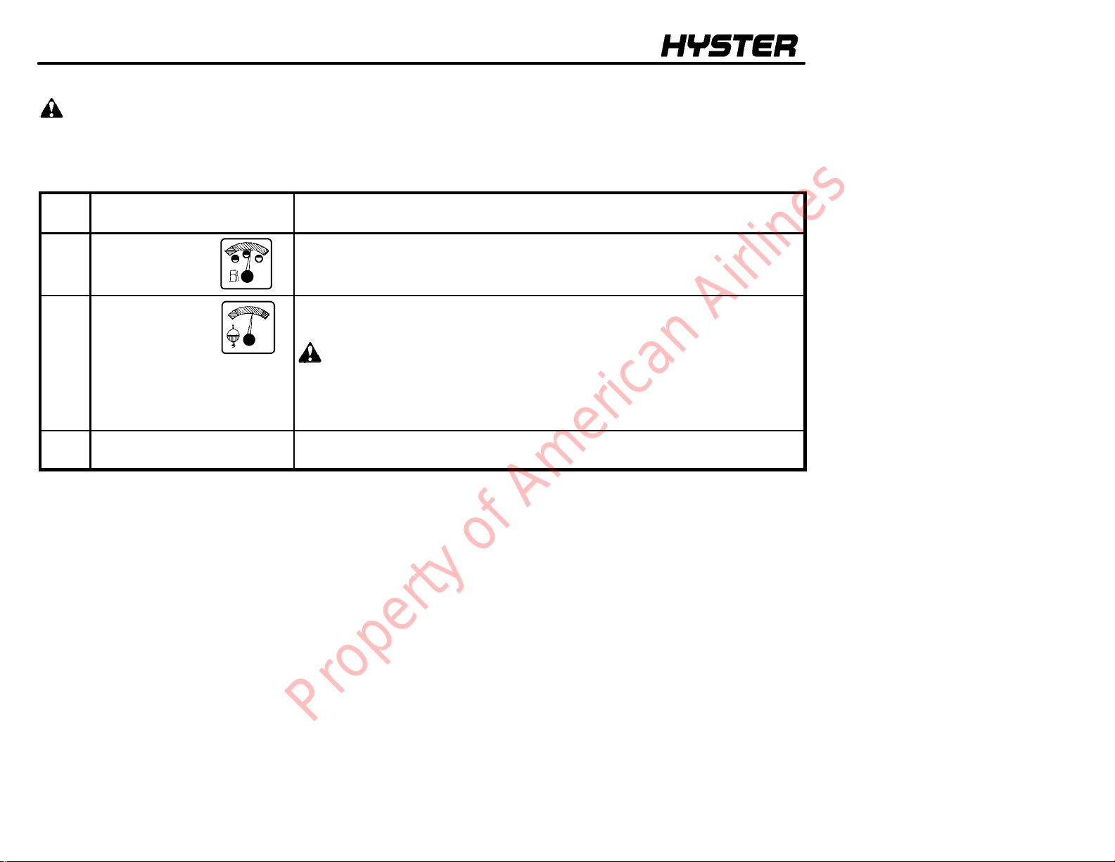
TABLE 1. INSTRUMENTS (See FIGURE 5.)
ITEM
NO.
1
2
Fuel Gauge
Coolant
Temperature
Gauge
ITEM
FUNCTION
This gauge indicates the amount of fuel in the gasoline or diesel fuel tank.
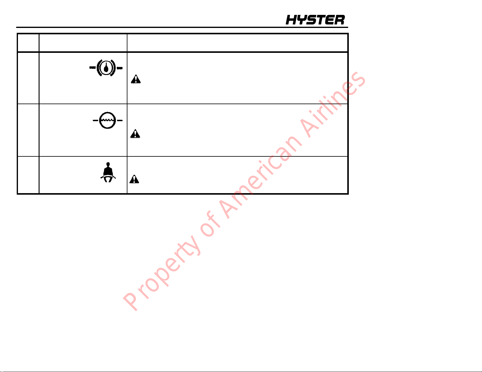
This gauge indicates engine coolant temperature when the key switch is in the
ON position. During normal operation the gauge needle will be in the green
area.
CAUTION
Do not continue to operate the lift truck when the gauge indicates that
the engine is too hot (needle in the red zone).
NOTE: Engine will stop after a 30 second warning buzzer if coolant is over
121°C (250°F) on S40--65XM series with protection system.
3 Hour Meter The hour meter operates when the key switch is in the ON position. Periodic
Maintenance recommendations are based on these hours.
18
Property of American Airlines
MODEL DESCRIPTION
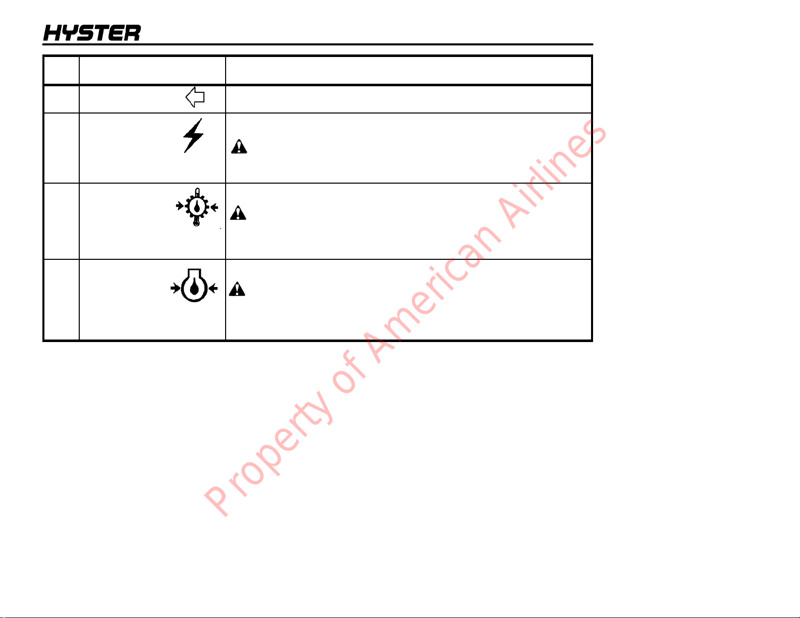
ITEM
NO.
4
Left--Hand
Turn Indicator
5 Warning Light,
Alternator
6
Warning light,
Transmission
Oil Temperature
7 Warning Light,
Engine Oil
Pressure
ITEM FUNCTION
The light is on when the turn indicator lever is in the left turn position.
The light will be ON when the key switch is ON and the engine is not running.
The light must go OFF when the engine is running.
CAUTION
Do not continue to operate the lift truck if the red light is ON at engine
speeds above idle.
The red light is ON when the key switch is in the START position and must go
OFF when the engine is running.
CAUTION
Do not continue to operate the lift truck if the red light is ON.
NOTE: Engine will stop after a 30 second warning buzzer if transmission oil is
over 121°C (250°F) on S45--65XM series with protection system.
The red light is ON when the key switch is in the ON position and must go OFF
when the engine is running.
CAUTION
Stop the engine immediately if the red light is ON while the engine is
running.
NOTE: Engine will stop after a 30 second warning buzzer if engine oil pressure
is less than 13.8 kPa (2 psi) on S40--65XM series with protection system.
19
Property of American Airlines
MODEL DESCRIPTION
ITEM
NO.
8 Warning Light,
Brake Fluid
Level
9 Warning Light,
Coolant Level in
the Radiator
(Used only on
S40--65XM model trucks.)
10 Warning Light,
Fasten Seat Belt
ITEM FUNCTION
The red light is ON when the key switch is in the START position and must go
OFF when the engine is running. If the light is ON when the engine is running,
the brake fluid level in the reservoir is too low.
CAUTION
Do not continue to operate the lift truck if the light is ON during
operation.
The red light is ON when the key switch is in the START position and must go
OFF when the engine is running. If the light is ON when the engine is running,
the level of the coolant in the radiator is too low.
CAUTION
Do not continue to operate the lift truck if the light is ON during
operation.
The red light is ON for ten seconds anytime the key switch is turned to the ON
position.
WARNING
Always fasten the seat belt when operating the lift truck.
20
Property of American Airlines
MODEL DESCRIPTION
ITEM
NO.
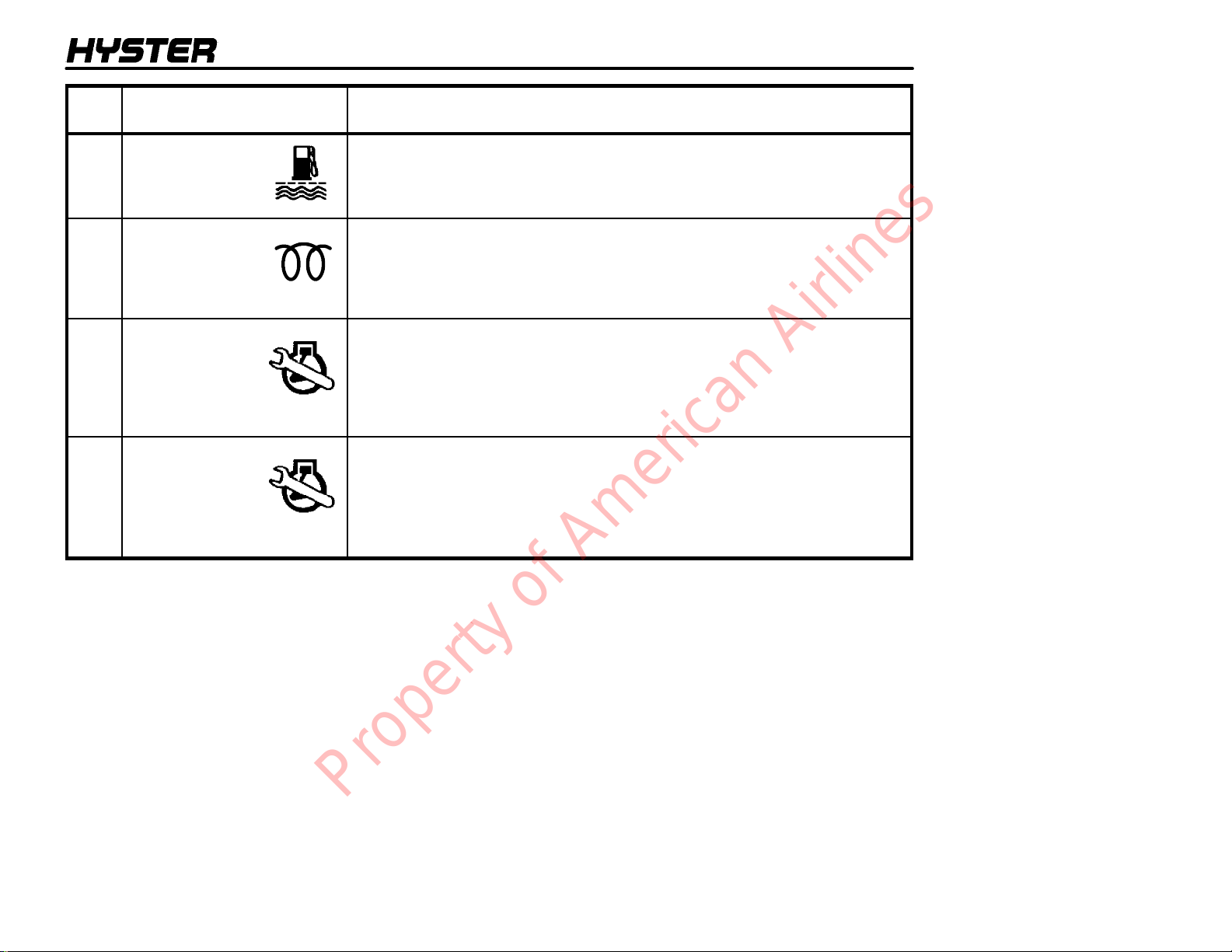
11
Water separator
Warning Light,
(Diesel Only)
12 Indicator Light,
Cold Start
(Diesel Only)
13 Malfunction
Indicator Lamp
(Lift trucks with
GM 3.0L engine, gas
fuel system)
13 Malfunction
Indicator Lamp
(Lift trucks with Gas-
oline or LPG closed
loop low emission
system)
ITEM FUNCTION
The red light is ON when the key switch is in the START position and must go
OFF when the engine is running. If the light is ON when the engine is running,
the water separator must be drained.
The red light is ON when the key switch is ON and the glow plugs are
activated. The length of time that the light is ON (glow plugs activated) is
determined by the temperature of the engine. When the light goes out, the
engine can be started. When the starter is cranking, the light will come ON
again until the starter is off and the engine is running.
This light will be ON when the key switch is ON and the engine is not running.
This light will illuminate when the Electronic Control Module computer senses a
fault in the operation of the engine. If the engine will start, the operation of the
engine will not be correct until the fault is corrected. A trained service person
must make repairs and adjustments if this light is ON when the engine is
running.
This light will be ON when the key switch is ON and the engine is not running.
This light will illuminate when the Electronic Control Module computer senses a
fault in the operation of the closed loop low emission system and the engine is
running. A trained service person must make repairs and adjustments if this
light is ON when the engine is running.
21
Property of American Airlines
MODEL DESCRIPTION
ITEM
NO.
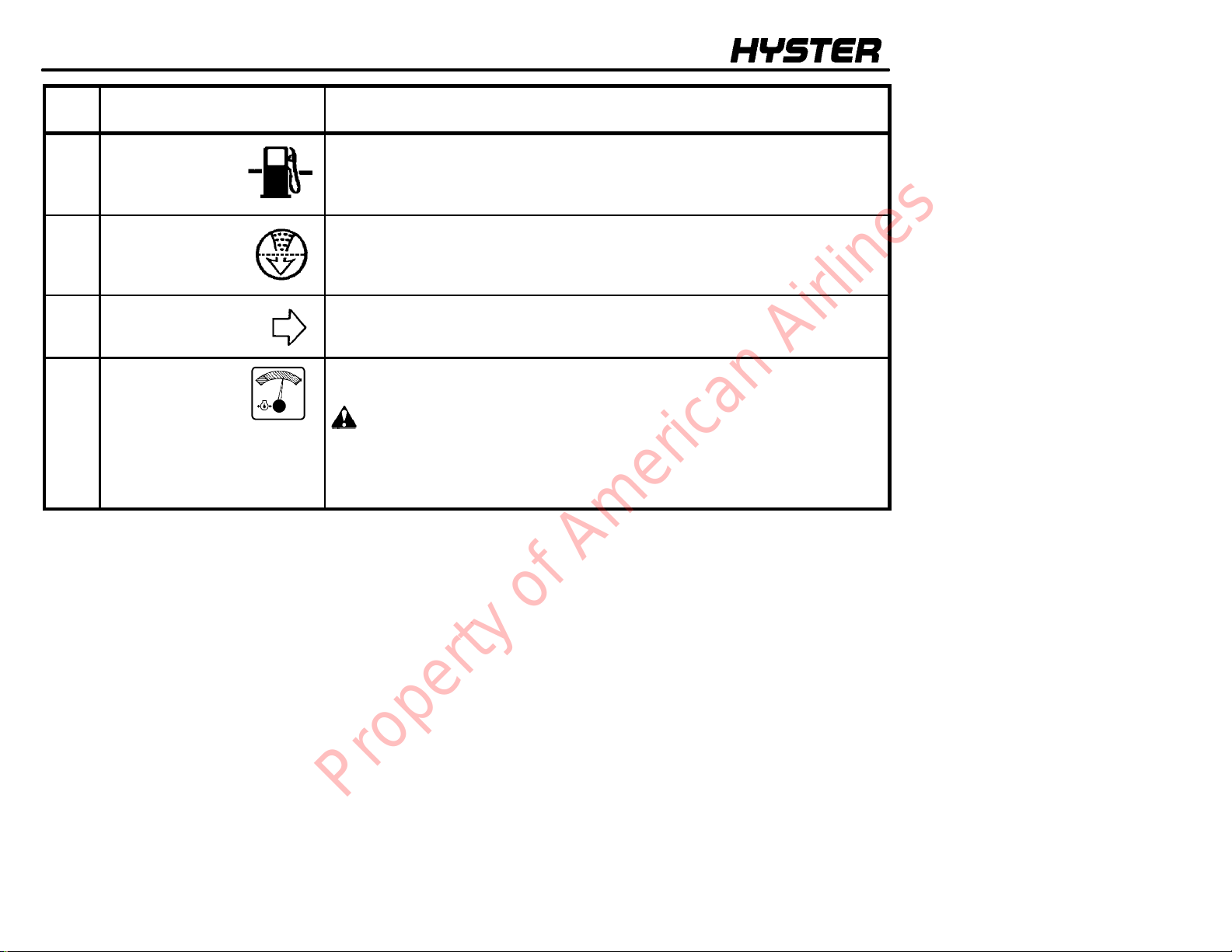
14 Indicator Light,
Low LPG Fuel
Level
15 Indicator Light,
Air Filter Restriction
16 Right--Hand
Turn Indicator
17
Engine Oil
Pressure Gauge
ITEM FUNCTION
The red light is ON when the key switch is in the START position and must go
OFF when the engine is running. If the light is ON when the engine is running,
the fuel level in the tank is low.
The red light is ON when the when the key switch is in the START position and
must go OFF when the engine is running. If the light is ON when the engine is
running, the air cleaner has a restriction and needs cleaning.
The light is on when the turn indicator lever is in the right turn position.
This gauge indicates the pressure of the oil in the engine. During normal
operation the gauge needle will be in the green area.
CAUTION
Do not continue to operate the lift truck when the gauge indicates low
oil pressure (needle in the red area).
NOTE: Engine will stop after a 30 second warning buzzer if engine oil pressure
is less than 13.8 kPa (2 psi) on S40--65XM series with protection system.
22
Property of American Airlines
MODEL DESCRIPTION
ITEM
NO.
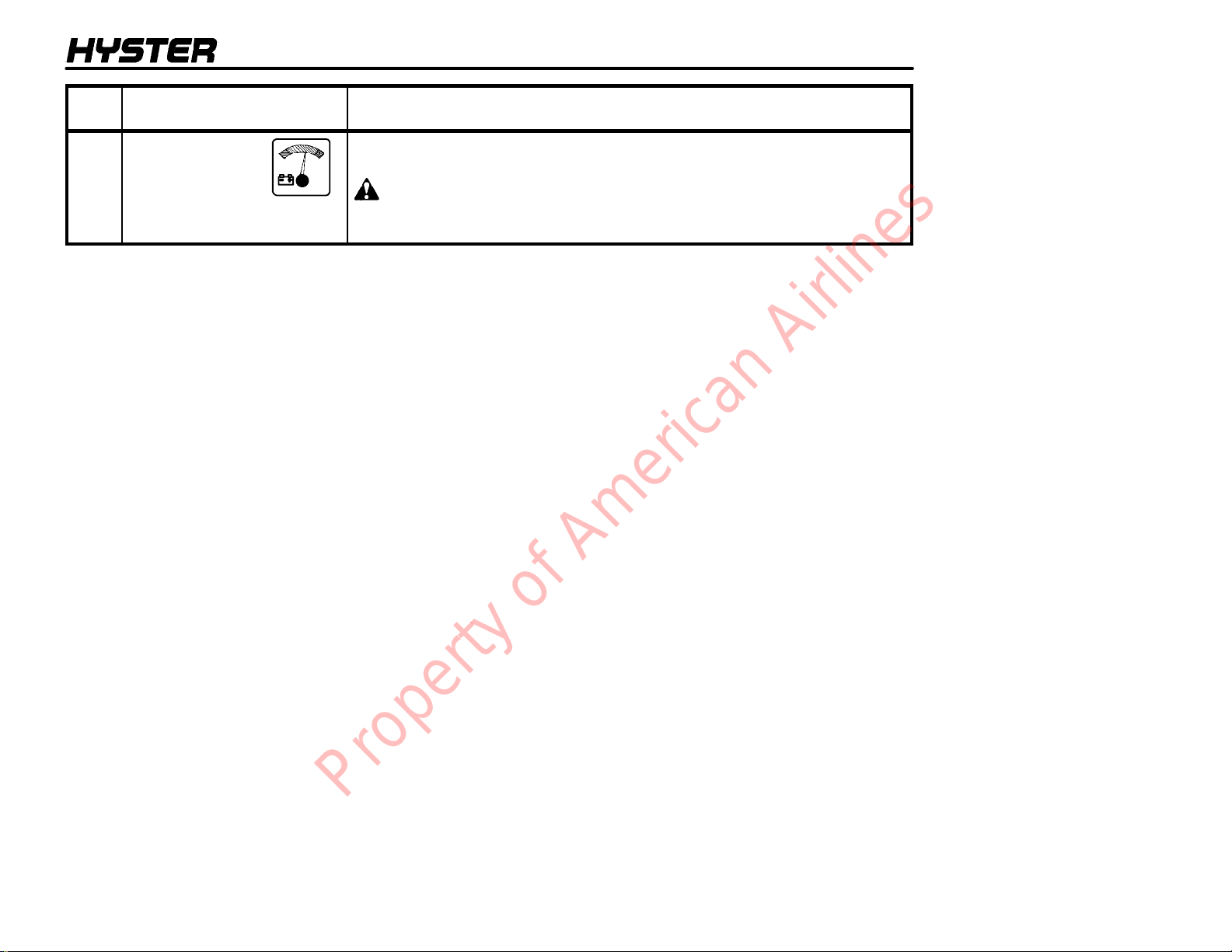
18 Voltmeter This gauge indicates the output of the alternator. During normal operation the
ITEM FUNCTION
gauge needle will be in the green area.
CAUTION
Do not continue to operate the lift truck when the gauge indicates in the
yellow or red areas of the gauge.
23
Property of American Airlines
MODEL DESCRIPTION
11
12
10
9
13
14
5
4
2
1
19
17
18
16
5
6
4
3
2
1
UNITS WITH DIRECTION CONTROL LEVER UNITS WITH MONOTROLR PEDAL
17
7
16
8
15
FIGURE 6. CONTROLS
11
12
13
14
24
Property of American Airlines
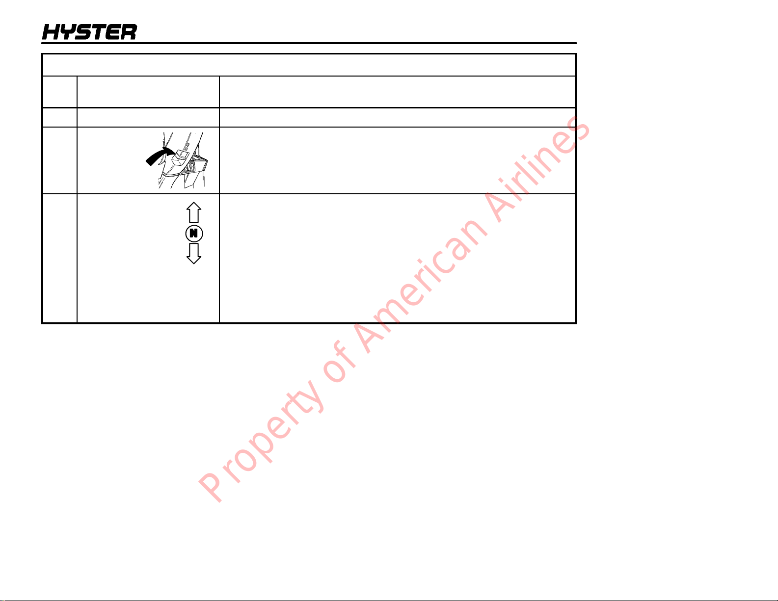
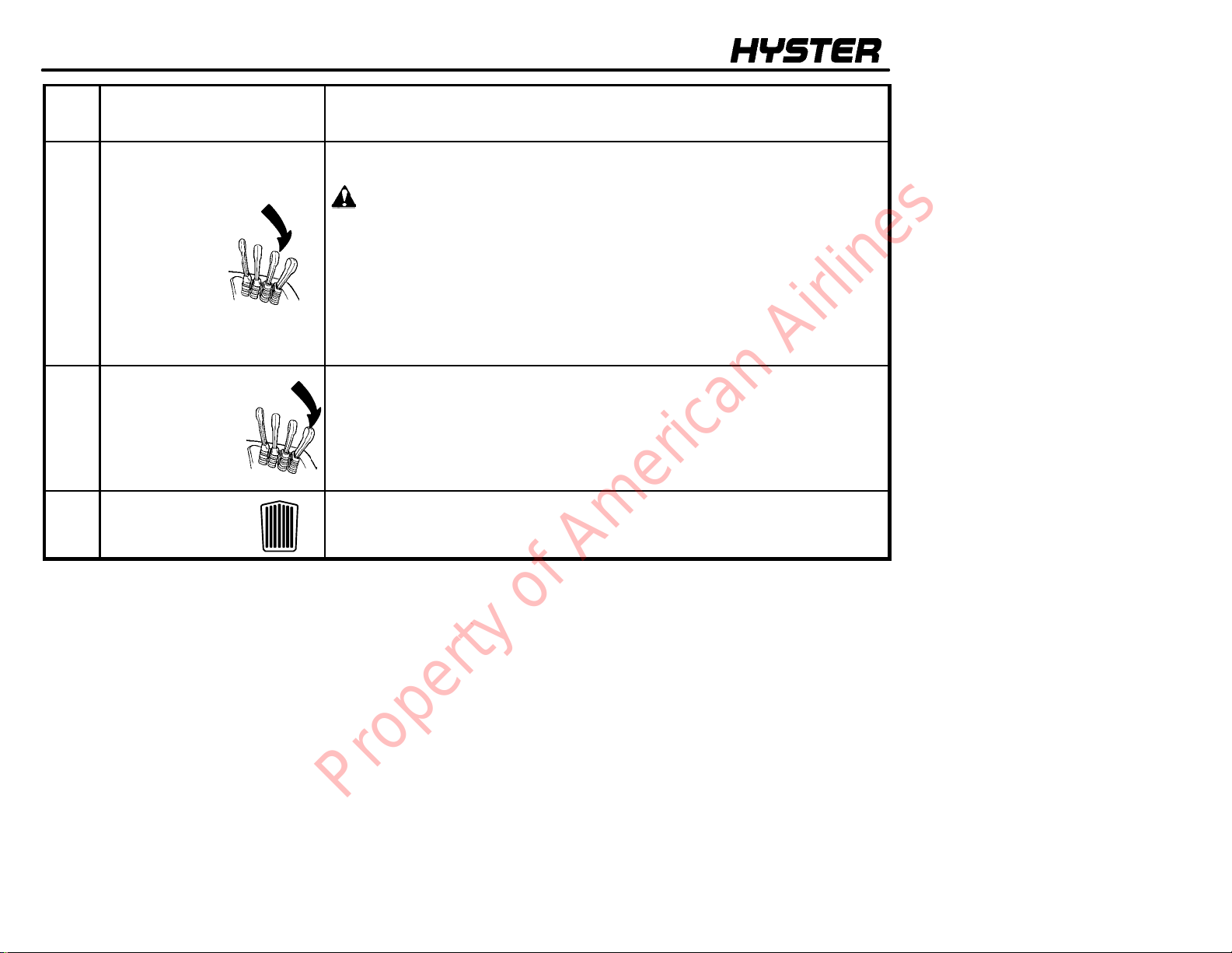
TABLE 2. CONTROLS (See FIGURE 6.)
MODEL DESCRIPTION
ITEM
NO.
1
Steering Wheel
2 Latch for Tilt
Steering Column
3 Direction Control
Lever
ITEM FUNCTION
The steering wheel controls the position of the steer tires.
A latch located on the lower left side of the steering column allows the operator
to select different positions for the steering wheel. Raise the latch to release the
steering column. Move the steering column to the selected position. Release
the latch to lock the steering column in position.
The direction control lever for the transmission is on the left side of the steering
column. The direction control lever is used on lift trucks without a
MONOTROLR pedal. This direction control lever has three positions:
FORWARD, NEUTRAL (N) and REVERSE. Move the lever to one of the
direction positions for travel. The direction control lever must be in the
NEUTRAL (N) position before the engine can be started. The reverse lights
and the optional reverse alarm will be on in the REVERSE position during
normal operation.
NOTE: There is a switch in the seat that actuates an audible buzzer. If the
operator leaves the seat with the key switch ON and the lever is not in
NEUTRAL, the buzzer will pulse ON and OFF for 10 seconds.
25
Property of American Airlines
MODEL DESCRIPTION
ITEM
NO.
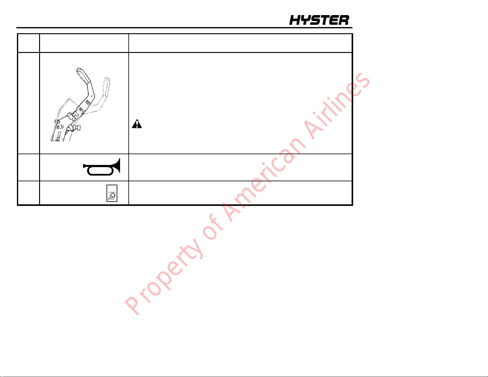
4 Parking Brake Lever The lift truck is equipped with a lever to apply the parking brake. Pull the lever
ITEM FUNCTION
to apply the parking brake. Use your thumb to release the button on the lever
when the lever is moved to release the parking brake.
On lift trucks with a MONOTROLR pedal, applying the parking brake puts the
transmission in NEUTRAL. The parking brake must be applied when leaving
the lift truck or when starting the engine.
NOTE: There is a switch in the seat that actuates an audible buzzer. If the
operator leaves the seat or turns the key to the OFF position without applying
the parking brake, the buzzer will be ON for 10 seconds.
WARNING
Correct adjustment is necessary to provide adequate braking. See the
MAINTENANCE section for adjustment procedures.
Always apply the parking brake when leaving the lift truck.
5
Horn
6 Switch The switch controls the operation of front drive lights. Push on the top of the
The horn button controls the operation of the horn.
switch to turn the lights ON.
26
Property of American Airlines
MODEL DESCRIPTION
ITEM
NO.
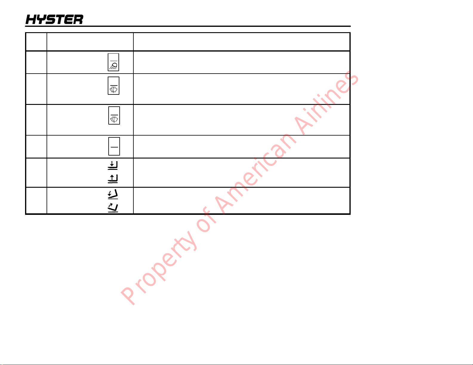
7 Switch The switch controls the operation of the rear drive lights. Push on the top of the
8 Switch The switch controls the operation of the front windshield wiper and windshield
9 Switch The switch controls the operation of rear windshield wiper and windshield
10 Switch The switch controls the operation of the heater. Push on the top of the switch to
11
Lift/Lower
Control
Lever
12 Tilt
Control
Lever
ITEM FUNCTION
switch to turn the lights ON.
washer. Push the front of the switch to the first position to turn ON the
windshield wiper. Push the front of the switch past the ON position to activate
the windshield washer.
washer. Push the front of the switch to the first position to turn ON the
windshield wiper. Push the front of the switch past the ON position to activate
the windshield washer.
turn the heater ON.
The lift/lower control lever is the first lever to the right of the operator’s seat.
Pull backward on the control lever to raise the carriage and forks. Push the
control lever forward to lower the carriage and forks.
The tilt control lever is on the right of the lift/lower control lever. Push the
control lever forward to tilt the mast and forks forward. Pull backward on the
control lever to tilt the mast and forks backward.
27
Property of American Airlines
MODEL DESCRIPTION
ITEM
NO.
13 Control Leverfor Auxiliary
Hydraulic Functions (3
lever). See FIGURE 6.
14 Control Leverfor Auxiliary
Hydraulic Functions (4
lever).
See FIGURE 6.
15
Accelerator Pedal
ITEM FUNCTION
rd
The third control lever is installed to the right of the tilt control lever. This control
lever can have two methods of operation, depending on the attachment.
WARNING
The control lever with a detent must be installed when an attachment
with a clamp is installed. See your dealer for Hyster lift trucks to get the
correct control lever.
Control Lever with a Detent -- Attachments with a clamp action: The lever
is spring--loaded toward the operator. The lever is operated by moving it to the
right, then forward and backward.
Control Lever without a Detent -- Attachments without a clamp action:
The lever is operated by moving it forward and backward.
th
The fourth control lever is installed to the right of the third control lever. The
lever is spring--loaded toward the operator. The lever is operated by moving it
to the right, then forward and backward.
This pedal controls the speed of the engine and is operated by the operator’s
right foot. It is used on units that have a direction control lever.
28
Property of American Airlines
 Loading...