

Hyster S70XL, S80XL, S120XL D004, S135XL, S155XL Operating Manual
...
OPERATING MANUAL
SPACESAVER
S70XL, S80XL, S80XL BCS, S100XL,
S120XLS, S120XL (D004)
S135XL, S155XL, S155XLS, S135XL
(B024, C024)
DO NOT REMOVE THIS MANUAL FROM THIS UNIT
, S155XL
2
2
Property of American Airlines
HYSTER COMPANY P ART NO. 897366
LIFT TRUCK MODEL SERIAL NUMBER
ENGINE MODEL SERIAL NUMBER
TRANSMISSION TYPE SERIAL NUMBER
MAST LIFT HEIGHT GROUP NUMBER
CARRIAGE TYPE GROUP NUMBER
DRIVE TIRE SIZE STEERING TIRE SIZE
SPECIAL EQUIPMENT OR ATTACHMENTS
Hyster,
countries.
EZXchanget,HSMt, ReachStackert, SitDrivet, StanDrivet, Multiquipt, and Unisourcet are trademarks of Hyster
Company in the united States and/or in certain countries where rights in unregistered trademarks are recognized. Hyster
Company products included in this document may be covered by U.S. Patenet No. 6,684,148 and other U.S. and foreign
patents pending. EHyster Company 2005. All rights reserved.
,Fortist, Fortenst, Pacesetter VSMt, DuraMatcht, Spectrumt, TouchPointt, TouchControlt,
,Vista, MONOTROL and Yardmaster are registered trademarks of Hyster Company in certain
Property of American Airlines

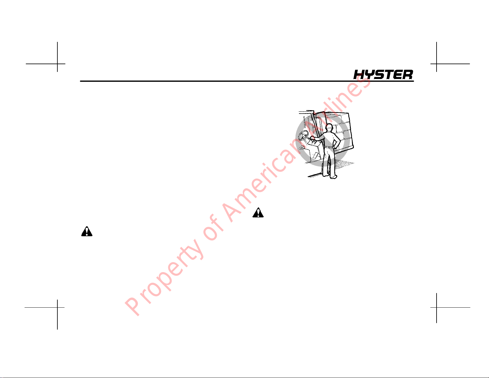
FOREWORD
FOREWORD
To OWNERS, USERS, and OPERATORS:
The safe and efficient operation of a lift truck requires
skill and alertness on the part of the operator. To develop
the skill required the operator must:
• receive training in the proper operation of THIS lift
truck.
• understand the capabilities and limitations of the lift
truck.
• become familiar with the construction of the lift truck
and see that it is maintained in good condition.
• read and understand the warnings and operating
procedures in this manual.
In additionaqualified person,experienced in lift truck operation, must guide a new operator through several driving and
load handling operations before the new operator attempts
to operate the lift truck alone.
It is the responsibility of the employer to make sure that
the operator can see, hear, and has the physical and mental ability to operate the equipment safely.
Various laws and regulations require the employer to train
lift truck operators. These laws and regulations include:
Occupational Safety and Health Act (USA)
Canada Material Handling Regulations
NOTE: A comprehensive operator training program is
available from HYSTER COMPANY. For further details,
contact your dealer for Hyster lift trucks.
This OPERATING MANUAL contains information necessary for the operation and maintenance of a basic fork lift
truck. Optional equipment is sometimes installed that can
change some operating characteristics described in this
manual. Make sure the necessary instructions are available and understood before operating the lift truck.
Some of the components and systems described in this
OPERATINGMANUALwillNOTbeinstalledonyourunit.
If you have a question about any item described, contact
your dealer for Hyster lift trucks.
HYSTER COMPANY 2005 897366 -- ENGLISH
1
Property of American Airlines
FOREWORD
Additional information that describes the safe operation
and use of lift trucks is available from the following
sources:
• employment safety and health standards or regulations
(Examples: “Occupational Safety and Health Standards
(USA)”, “Canada Material Handling Regulations”.
• safety codes and standards (Example: Industrial Truck
Standards Development Foundation, ITSDF B56.1,
Safety Standard For Low Lift And High Lift Trucks.
• publications from government safety agencies,
government insurers, private insurers and private
organizations (Example: Accident Prevention Manual
For Industrial Operations, from the National Safety
Council).
NOTE: Hyster lift trucks are not intended for use on public
roads.
NOTE: The following symbols and words indicate safety
information in this manual:
W ARNING
Indicates a condition that can cause injury!
CAUTION
Indicates a condition that can cause property damage!
2
Property of American Airlines

CONTENTS
CONTENTS
FOREWORD 1..................................
CONTENTS 3...................................
MODEL DESCRIPTION 7.........................
GENERAL 7..................................
OPERATOR PROTECTION EQUIPMENT 8......
NAMEPLATE 8...............................
SAFETY LABELS 9............................
INSTRUMENTS AND CONTROLS 13.............
OPERATING PROCEDURES 23....................
GENERAL 23..................................
Know Your Lift Truck 23......................
Stability and Center Of Gravity 23..............
Capacity
(Weight and Load Center) 25..................
INSPECTION BEFORE OPERATION 25..........
Checks With the Engine Stopped 25...........
Starting Procedures 26.......................
Gasoline Or LPG Engine 26...................
Diesel Engine 27............................
Checks With the Engine Running 28...........
OPERATING TECHNIQUES 29..................
Basic Operating Procedures 29................
Driving And Direction Changes 32.............
Operator Presence System 33................
Inching 33..................................
Steering (Turning) 34........................
Load Handling, General 36...................
Load Handling, Lifting,
Lowering, And Tilting 38......................
Load Handling, How To Engage And Disengage A
Load 40....................................
Load Handling, Traveling 43..................
HIGHWAY TRUCKS, RAILROAD CARS AND
DOCKS 47....................................
ATTACHMENTS 49.............................
STOPPING 49.................................
PARKING 49..................................
MAINTENANCE 51...............................
GENERAL 51..................................
HOW TO MOVE A DISABLED LIFT TRUCK 52.....
HowToTowTheLiftTruck 52.................
How To Put A Lift Truck On Blocks 53..........
HowToRaiseTheDriveTires 53..............
How To Raise The Steering Tires 53...........
3
Property of American Airlines
CONTENTS
MAINTENANCE SCHEDULE 55....................
HOW TO MAKE THE CHECKS WITH THE
ENGINE STOPPED 69..........................
Hydraulic System Oil 69......................
Engine Oil 72...............................
Drive Belts 72...............................
Cooling System 72..........................
Air Filter 74.................................
Fuel System 74.............................
Primary Fuel Filter, Diesel Engine 74...........
Battery 75.................................
Tires And Wheels 76.........................
Forks 77...................................
Forks, Adjustment 77........................
Forks, Removal And Installation 77............
Inspection Of Forks, Mast, and Lift Chains 80....
Safety Labels 82............................
Operator Restraint System 83................
Automatic Locking Retractor (ALR) 83..........
Emergency Locking Retractor (ELR) 83.........
Hood And Seat Latches 84...................
HOW TO MAKE THE CHECKS WITH THE
ENGINE RUNNING 86..........................
Gauges, Lights, Horn And Fuses 87............
Oil Level, Powershift Transmission 90..........
Oil Level, Oil Clutch System 90................
Control Levers and Pedals 91.................
Lift System Operation 92.....................
Inching/Brake Pedal 92.......................
Service Brakes 93...........................
Parking Brake 93............................
Steering System 93..........................
HOW TO ADD FUEL TO THE LIFT TRUCK 94.....
Liquified Petroleum Gas (LPG) 94.............
Gasoline Or Diesel Fuel 97...................
WHEELS AND TIRES 98..........................
HOW TO CHANGE A SOLID RUBBER TIRE 98....
INSTALLTHE WHEELS 99......................
Steering Wheels 99..........................
Drive Wheels 99.............................
OPERATING PROCEDURES FOR A NEW OR
REBUILT ENGINE 99...........................
4
Property of American Airlines
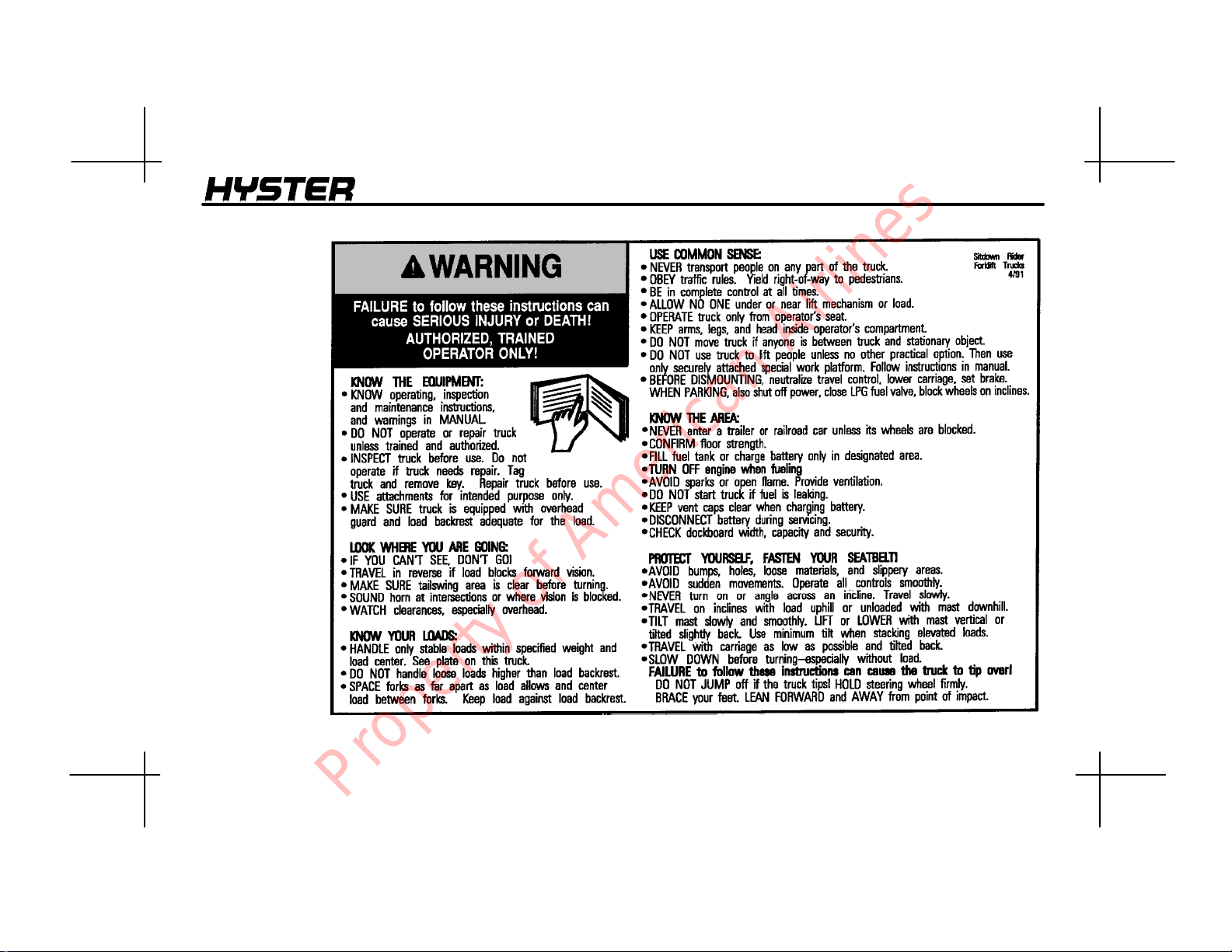
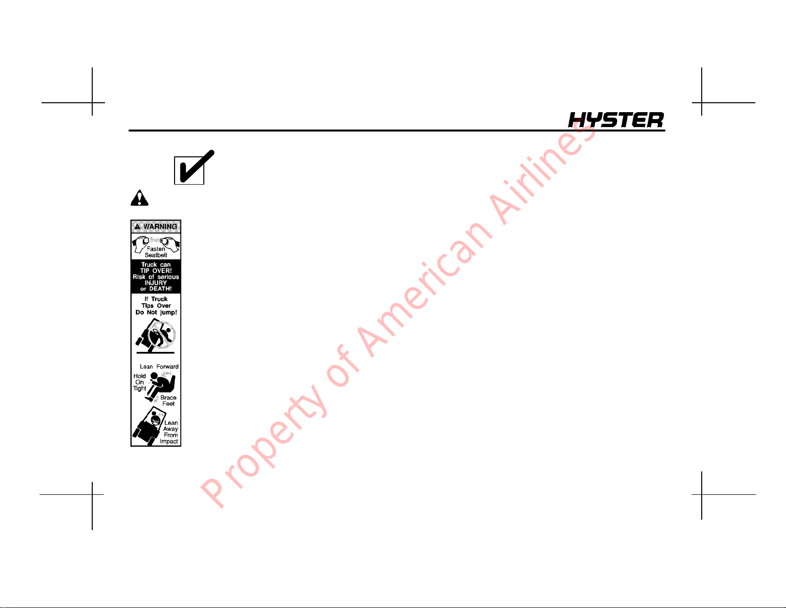
A WARNING
label with this
information
must be on
the lift truck.
W ARNING
5
Property of American Airlines
MODEL DESCRIPTION
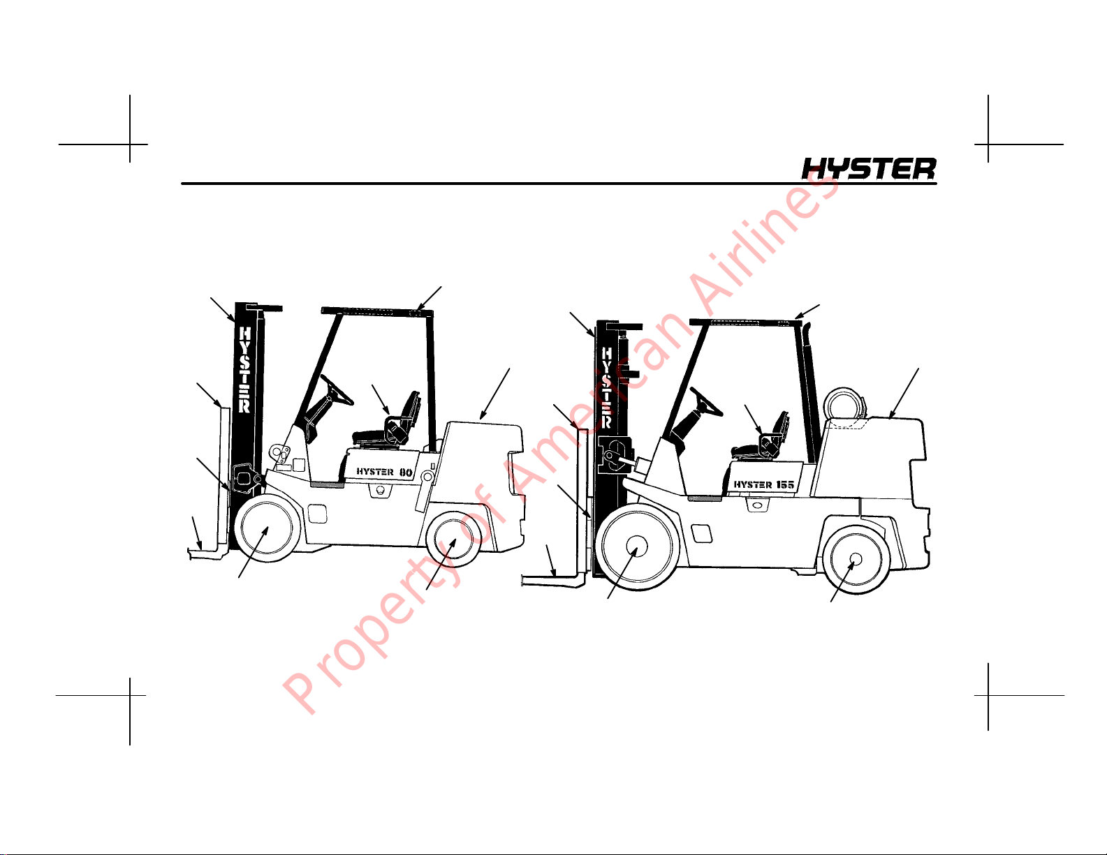
1. OVERHEAD GUARD
2. COUNTERWEIGHT
3. STEERING AXLE
4. DRIVE AXLE
5
8
7
6
S70 --120XL
4
9
1
3
5. MAST
6. FORKS
7. CARRIAGE
8. LOAD BACKREST EXTENSION
9. SEAT BELT AND HIP RESTRAINT BRACKET
5
22
8
7
6
4
9
S135--155XL
1
3
1244312177
FIGURE 1. MODEL VIEW SHOWING MAJOR COMPONENTS
6
Property of American Airlines
MODEL DESCRIPTION
MODEL DESCRIPTION
GENERAL
This Operating Manual is for the following models of lift
trucks:
• the S70--120XL (D004) series includes the S70XL,
S80XL, S80XL BCS, S100XL, S120XLS, and S120XL
• the S135--155XL (B024, C024) series includes the
S135XL, S135XL
The S70--120XL and the S135--155XL series of lift trucks
are available with a gasoline engine, an LPG fuel engine,
or a diesel engine.
The S70--120XL series of lift trucks has a single--speed
powershift transmission. The lift trucks can be equipped
with two kinds of controls:
• a MONOTROL pedal that controls both the forward
and reverse operation of the powershift transmission
and the speed of the engine.
• a direction control lever near the left side of the steering wheel that controls the forward and reverse operation of the powershift transmission. A separate accelerator pedal controls the engine speed.
, S155XL, S155XL2, and S155XLS.
2
The S135--155XL series of lift trucks can have either a
three--speed manual transmission with an oil clutch (B024
models only) or a two--speed powershift transmission.
Lift trucks with a three--speed manual transmission have
two control levers on the left side of the steering wheel.
One lever controls the forward and reverse direction of the
lift truck and the other lever is used to select the speed
range. These lift trucks have a clutch pedal and an accelerator pedal.
The two--speed powershift transmission has a range lever
on the left side of the steering column to control the two
speed ranges. The two--speed powershift transmission
can be equipped with two kinds of controls for forward and
reverse and engine speed control:
• a MONOTROL pedal that controls both the forward
and reverse operation of the powershift transmission
and the speed of the engine.
• a direction control lever near the left side of the steering wheel that controls the forward and reverse operation of the powershift transmission. A separate accelerator pedal controls the engine speed.
7
Property of American Airlines
MODEL DESCRIPTION
OPERATOR PROTECTION EQUIPMENT
The LOAD BACKREST EXTENSION is installed to keep
loose parts of the load from falling back toward the operator. It must be high enough, with openings small enough to
prevent the parts of the load from falling backwards. If a
load backrest extension that is different from the one installed on your lift truck is required, contact your Hyster lift
truck dealer.
The OVERHEAD GUARD is intended to offer reasonable
protection to the operator from falling objects, but can not
protect against every possible impact. Therefore, it must
not be considered a substitute for good judgment and care
when handling loads. Do not remove the overhead guard.
The SEAT BELT AND HIP RESTRAINT BRACKET provide additional means to help the operator keep the head
and torso substantially within the confines of the lift truck
frame and overhead guard if a tipover occurs. This restraint system is intended to reduce the risk of the head
and torso being trapped between the lift truck and the
ground, but it can not protect the operator against all possible injury in a tipover. The hip restraint bracket will help
the operator resist side movement if the seat belt is not
fastened. It is not a substitute for the seat belt. Always fasten the seat belt.
NAMEPLA TE
W ARNING
Any change to the lift truck, the tires or its equipment
can change the lifting capacity. If the Nameplate does
not show the maximum capacity, or if the lift truck
equipment, including the battery for electric trucks,
does not match that shown on the Nameplate, the lift
truck must not be operated.
The capacity is specified in kilograms (kg) and pounds
(lb). The capacity is the maximum load that the lift truck
can handle for the load condition shown on the Nameplate.
The maximum capacity for the lift truck, at full load height,
must be shown on the Nameplate. Special capacities with
the load height reduced or with optional load centers, may
also be shown on the Nameplate.
The lift truck serial number code is on the Nameplate. The
serial number code is also stamped on the lift truck frame.
8
Property of American Airlines
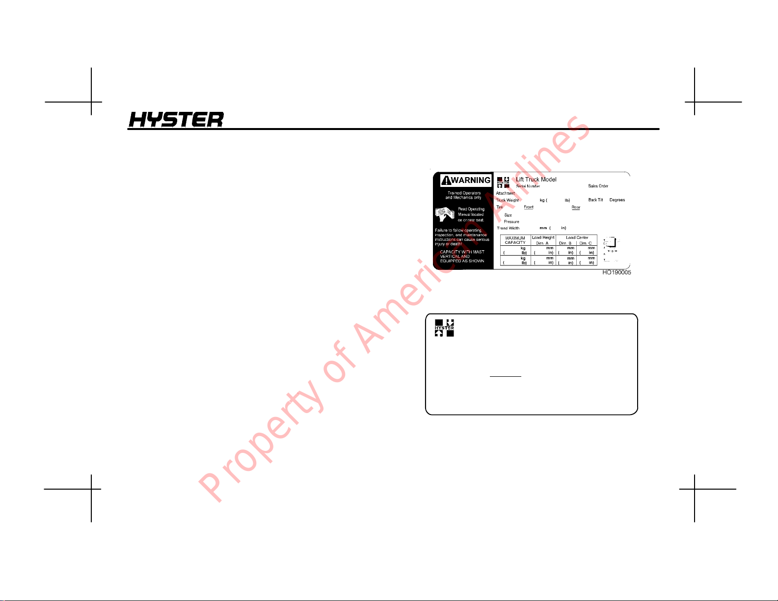
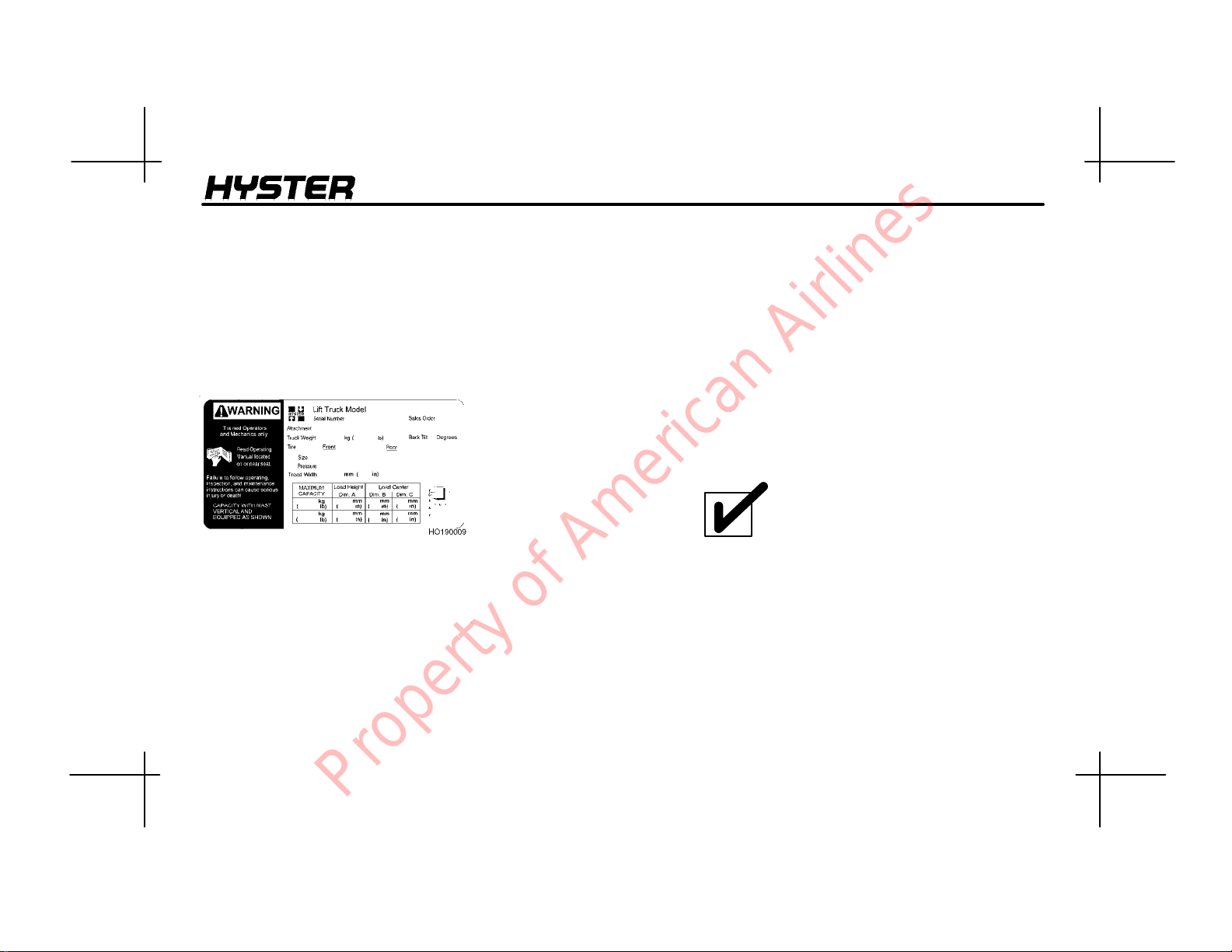
When a lift truck is shipped incomplete from the factory,
the nameplate is covered by a label as shown in
FIGURE 2. If your lift truck has this type of label, do not
operate the lift truck. Contact your dealer for HYSTER lift
trucks to obtain a complete nameplate.
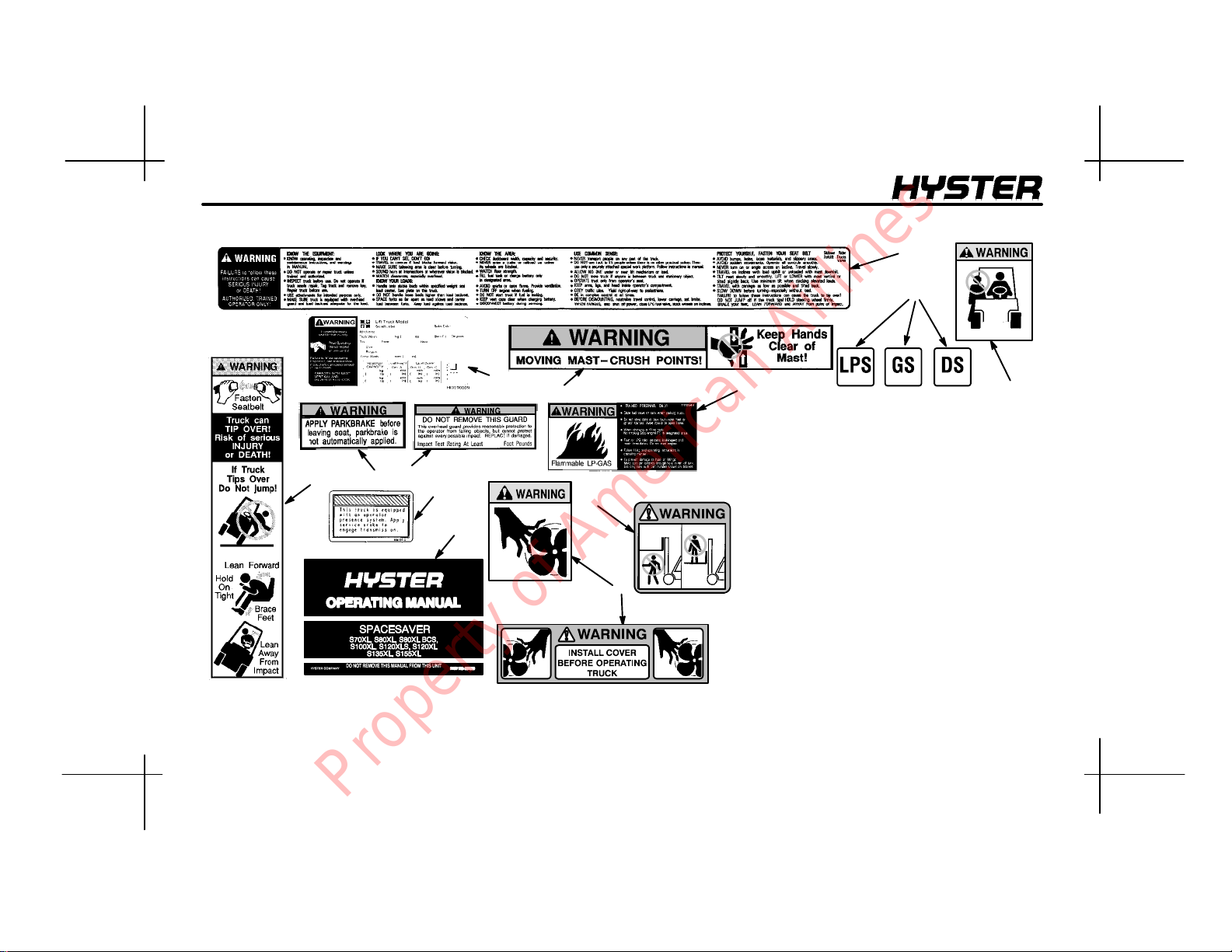
SAFETY LABELS
Safety labels are installed on the lift truck to give information about possible hazards. It is important that all safety
labels are installed on the lift truck and can be read. See
FIGURE 3.
MODEL DESCRIPTION
NAME PLATE
TRUCK MODEL
Serial no.
Approx. weight
NOTICE TO USER
This unit was shipped incomplete from factory/
The U.S.A. Occupational Safety and Health Act of 1970 and other national
safety codes require the installation of a completed Nameplate showing unit
configuration and rated capacity. Completed Nameplates may be obtained
through your HYSTER dealer.
LABEL
FIGURE 2. NAMEPLATE AND LABEL
9
Property of American Airlines
MODEL DESCRIPTION
1
7
10
3
4
6
11
13
2
FIGURE 3. WARNING AND SAFETY LABELS
12
5
8
10
1. WARNING, OPERATION
2. OPERA TING MANUAL
3. NAMEPLATE
4. IMPACT TEST
5. NO ONE ON OR UNDER FORKS
6. TIPOVER WARNING
7. FIRE SAFETY
8. FAN WARNING
9. NO RIDERS
10. FLAMMABLE LP--GAS
11. WARNING FOR PARKING BRAKE
12. MAST WARNING
13. OPERATOR PRESENCE SYSTEM
SEE THE PARTS MANUAL FOR THE
PART NUMBER AND LOCATION
9
Property of American Airlines

NOTE: THIRD--FUNCTION CONTROL LEVER (17a)
IS AVAILABLE ON ALL UNITS
10
1
4
6
3
16
15
MODEL DESCRIPTION
5
7
1
12
10
3
16
15
16
17
17a
11
17
2
8
9
POWERSHIFT TRANSMISSION WITH MONOTROL PEDAL
FIGURE 4. CONTROLS AND INSTRUMENTS, S70--120XL
1920
Property of American Airlines
11
2
8
20
POWERSHIFT TRANSMISSION WITH
DIRECTION CONTROL LEVER
18
9
17a
12189
11
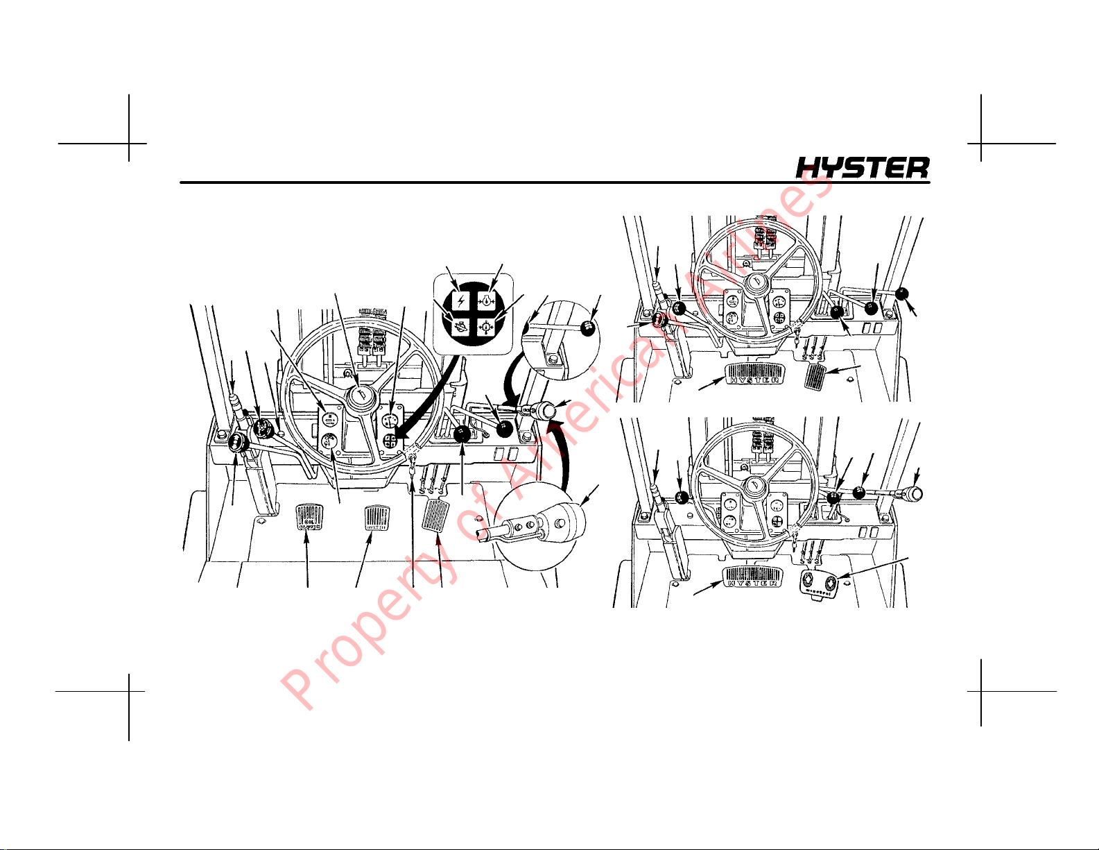
MODEL DESCRIPTION
NOTE: THIRD--FUNCTION CONTROL LEVER (17a)
IS AVAILABLE ON ALL UNITS
4
11
5
14
16
12
11
12
10
1
13
8
2
2122
MANUAL TRANSMISSION
17a
17
12
20
POWERSHIFT WITHOUT MONOTROL PEDAL
11
14
17a
20
POWERSHIFT WITH MONOTROL PEDAL
16
6
3
16
15
9
18
FIGURE 5. CONTROLS AND INSTRUMENTS, S135--155XL
7
12189
15
15
17
12402
18
16
17a
19
12189
Property of American Airlines
MODEL DESCRIPTION
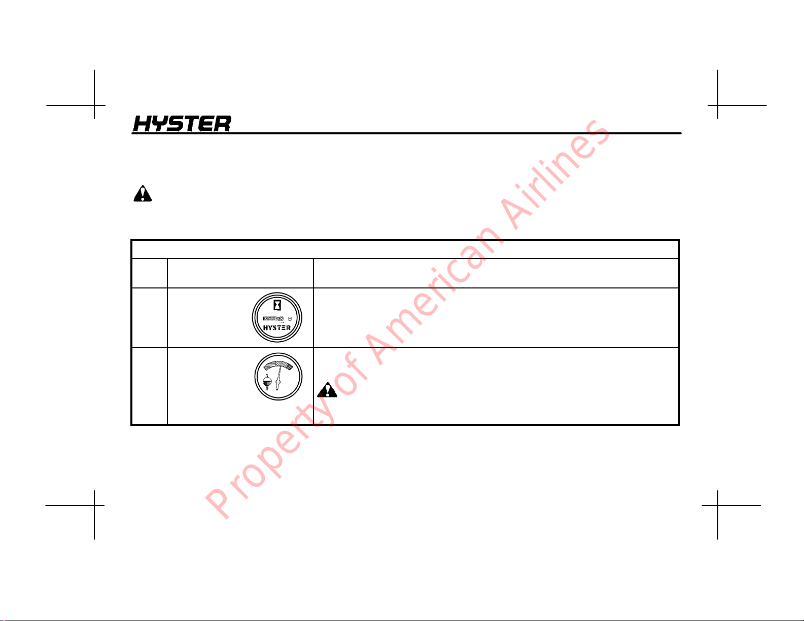
INSTRUMENTS AND CONTROLS
(See TABLE 1., TABLE 2., TABLE 3., FIGURE 4., and FIGURE 5.)
W ARNING
If any of the instruments, levers, or pedals do not operate as described in the following tables, report the problem
immediately. DO NOT operate the lift truck until the problem is corrected.
TABLE 1. INSTRUMENTS
ITEM
NO.
1 Hour Meter The hour meter operates when the key switch is in the ON position. Periodic
2 Coolant
Temperature
Gauge
ITEM FUNCTION
Maintenance recommendations are based on these hours.
Indicates engine coolant temperature when the key switch is in the ON
position. During normal operation, the needle will indicate in the green zone of
the gauge.
CAUTION
Do not continue to operate the lift truck when the gauge indicates that
the engine is too hot (needle in the red zone).
Property of American Airlines
13
MODEL DESCRIPTION
ITEM
NO.
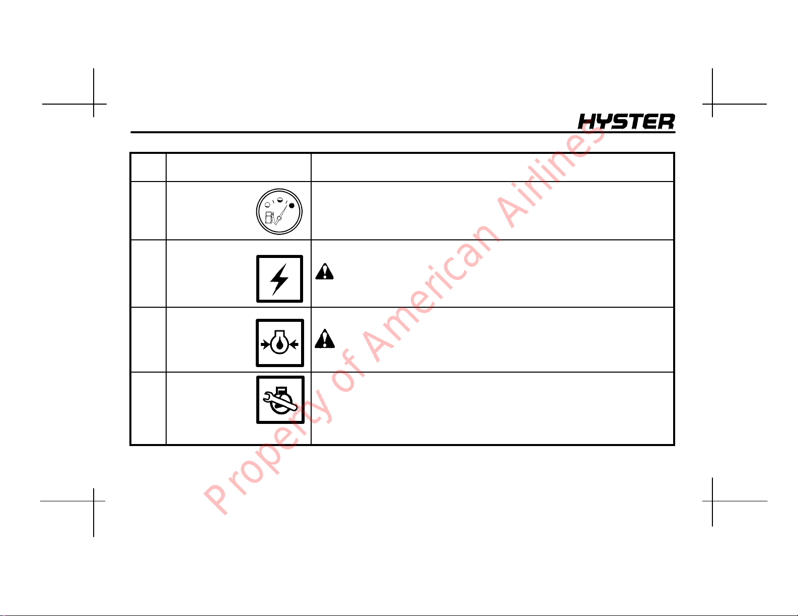
3 Fuel Gauge Indicates the amount of fuel in the gasoline or diesel fuel tank.
4 Warning Light,
Alternator
ITEM FUNCTION
The red light will be ON when the key switch is ON and the engine is not
running.
CAUTION
Do not continue to operate the lift truck if the red light is ON at engine
speeds above idle.
5 Warning Light,
Engine Oil
Pressure
The red light is ON when the key switch is in the START position.
CAUTION
Stop the engine immediately if the light is ON when the engine is running.
6
Warning Light,
“Check Engine”
Lift trucks with electronic engine control (electronic spark timing and fuel
injection). This light will be ON when the key switch is ON and the engine is not
running. This light will illuminate when the ECM computer senses a fault in the
operation of the engine. If the engine will start, the operation of the engine will
not be correct until the fault is corrected. A trained service person must make
repairs and adjustments if this light is ON when the engine is running.
14
Property of American Airlines
MODEL DESCRIPTION
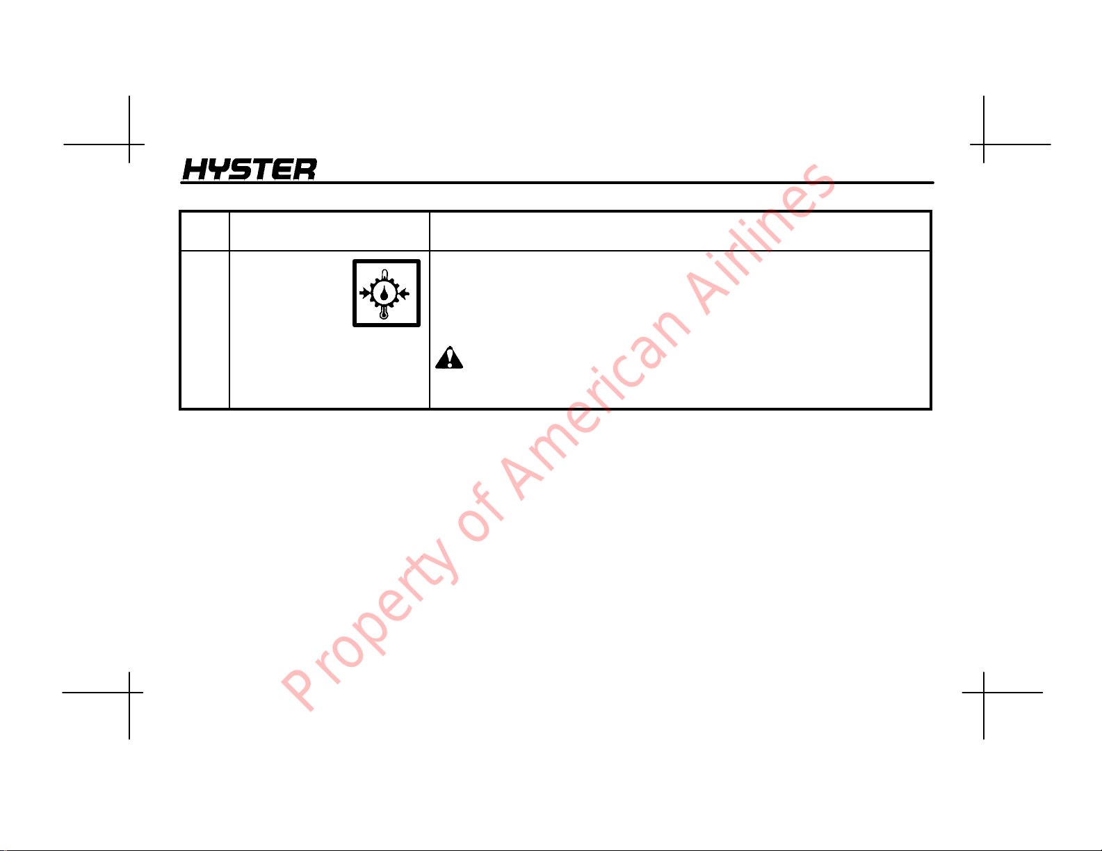
ITEM
NO.
7 Warning light,
Powershift
Transmission
Oil Temperature
or
Oil Pressure for
Clutch, Manual
Transmission
(S135--155XL)
ITEM FUNCTION
Powershift Transmission: The red light is ON when the key switch is in the
ST ART position.
Manual Transmission: The red light is ON when the oil pressure in the clutch
system is too low for continued operation. The red light is ON when the key
switch is ON and the engine is not running.
CAUTION
Do not continue to operate the lift truck if the light is ON during
operation.
15
Property of American Airlines
MODEL DESCRIPTION
K
TABLE 2. CONTROLS
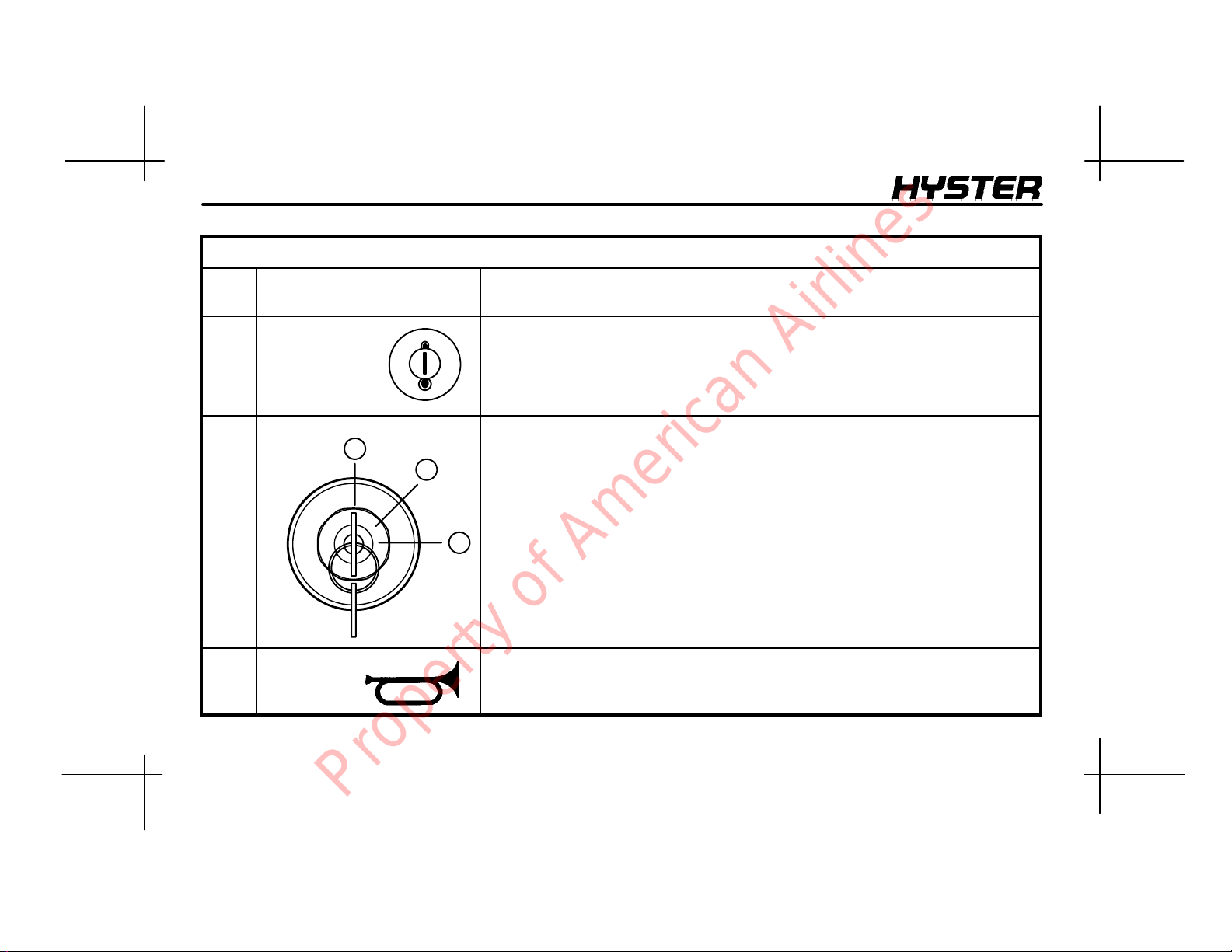
ITEM
NO.
8 Cold Start Aid The cold start aid is used on lift trucks with a diesel engine. For S70--120XL lift
9
10
ey
Switch
Horn
ITEM FUNCTION
trucks, the control button is to the left of the steering column. On S135XL,
S155XL lift trucks, the control button is on the top of the instrument panel. The
keyswitchmustbeintheON position before the cold start aid can be
energized.
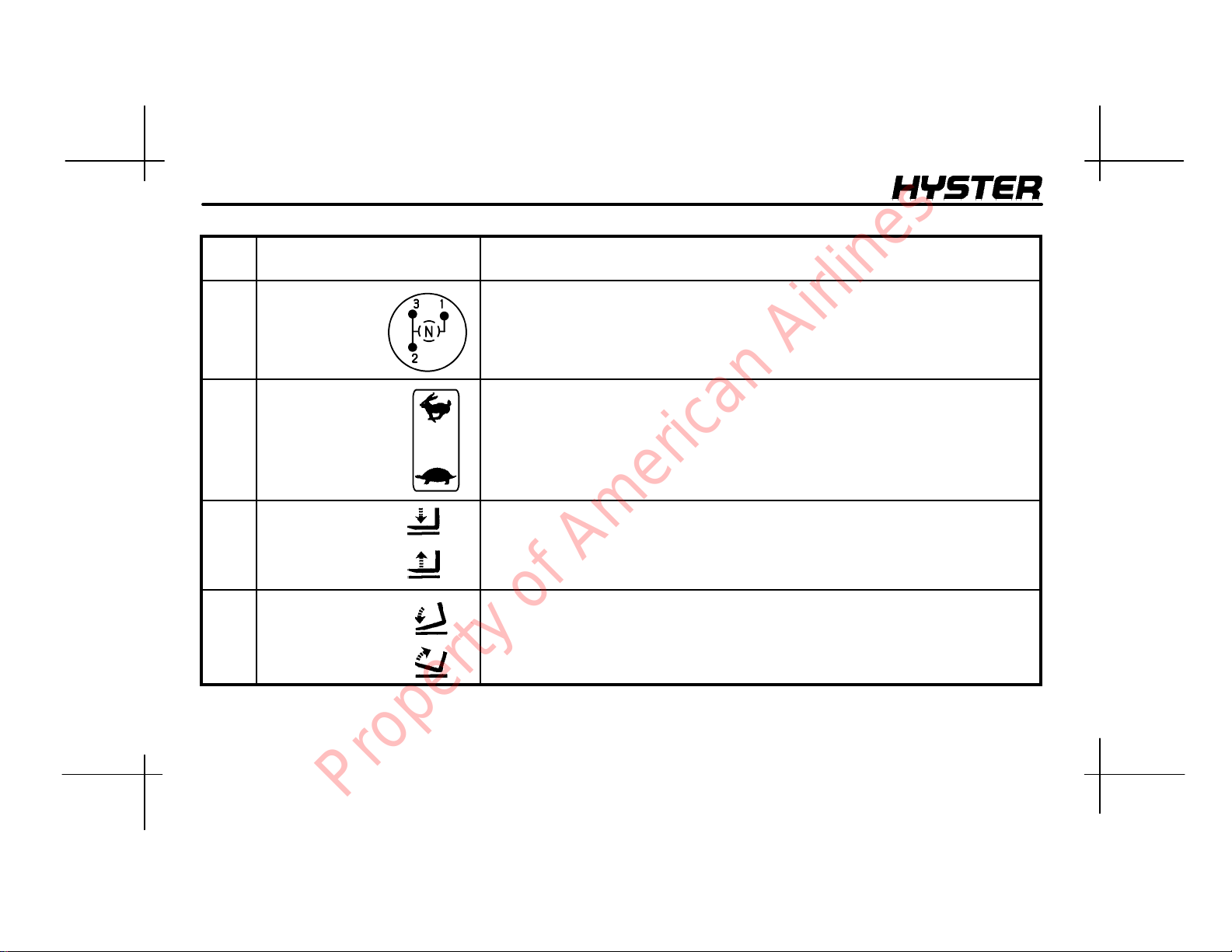
The key switch has three positions:
1
2
No. 1 Position: OFF position. Deenergizes all electric circuits except for the
horn and headlights.
No. 2 Position: ON position. Energizes all electric circuits except the starter
circuit. The key switch will be in this position during normal operation.
No. 3 Position: START position. Energizes the starter motor for starting the
3
engine. A spring returns the key to position No. 2 (ON position) when the key is
released.
NOTE: There is a mechanical lockout that prevents the key switch from being
returned to the START position without first being returned to the OFF position.
The horn button controls the operation of the horn.
16
Property of American Airlines
MODEL DESCRIPTION
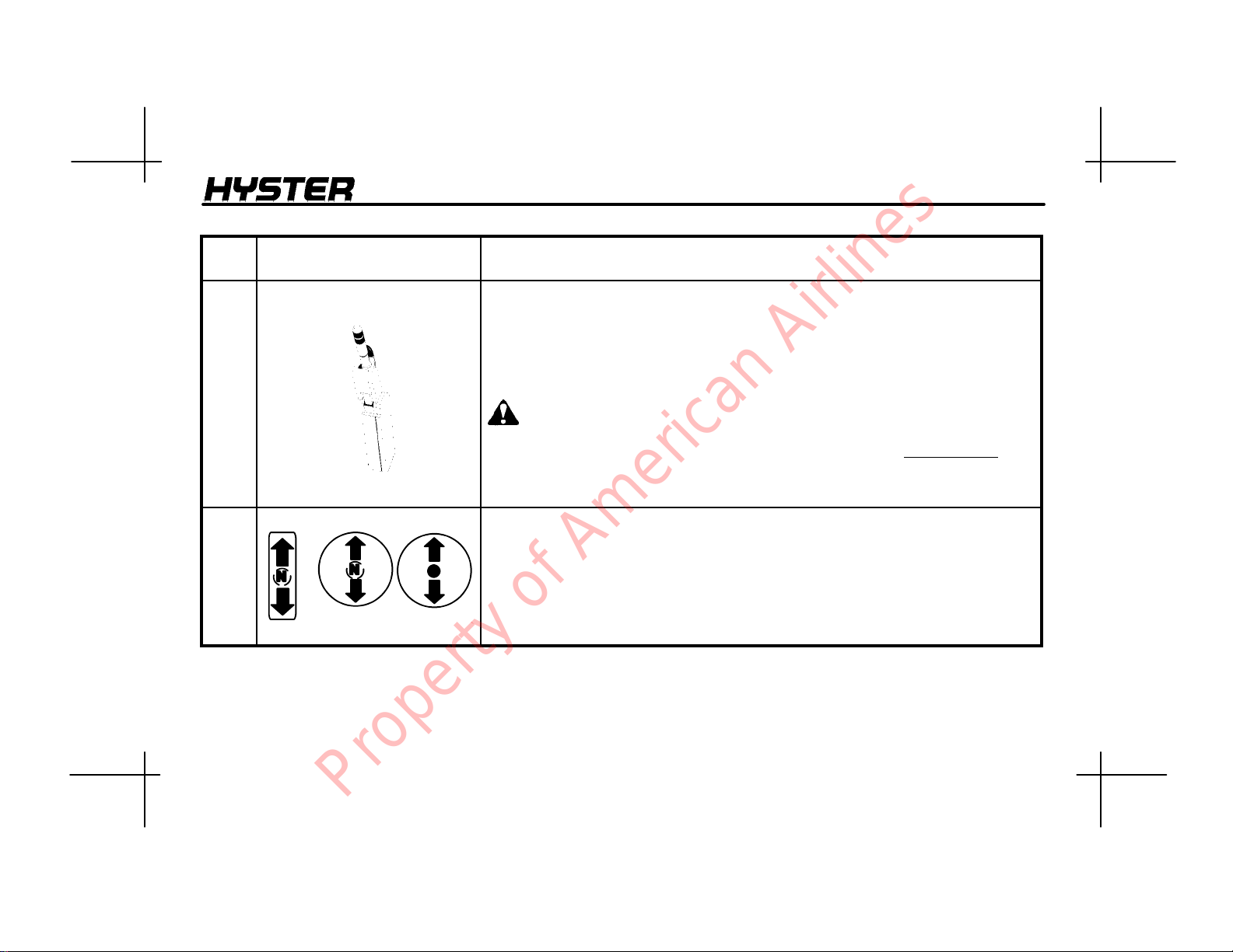
ITEM
NO.
11 Parking Brake Lever The lift truck is equipped with a lever to apply the parking brake. Pull the lever
ITEM FUNCTION
to the vertical position to apply the parking brake.
Lift trucks with a MONOTROL pedal: when the parking brake is applied, a
switch in the starting circuit is closed so that the engine can be started. The
switch also puts the transmission in NEUTRAL. Use your finger to release the
lock on the lever when the lever is moved to release the parking brake.
WARNING
Correct adjustment is necessary to provide adequate braking and to keep
the parking brake lever in the engaged position. See the Maintenance
section for adjustment procedures.
Always apply the parking brake when leaving the lift truck.
12 Direction Control Lever
S135--155XL
S70--120XL
The direction control for the transmission is to the left of the steering column.
The direction control lever is used on lift trucks with a manual transmission and
those lift trucks with a powershift transmission without a MONOTROL pedal.
The direction control lever has three positions: FORWARD, NEUTRAL (N), and
REVERSE. Move the lever to one of the direction positions for travel.
NOTE: The direction control lever must be in the NEUTRAL (N) position before
the engine can be started.
17
Property of American Airlines
MODEL DESCRIPTION
ITEM
NO.
13 Range Lever
(Manual
Transmission)
(S135--155XL)
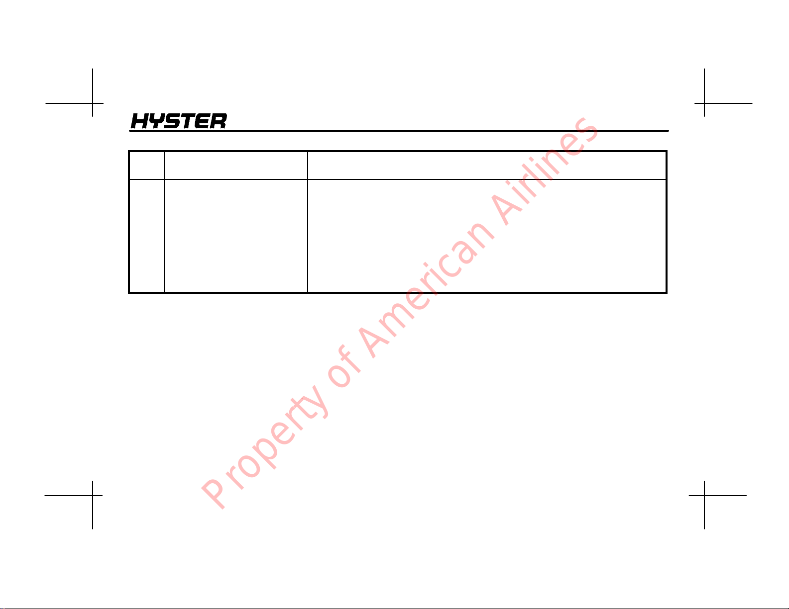
14 Range Lever
(Powershift
Transmission)
(S135--155XL
Only)
15 Lift/Lower
Control
Lever
16 Tilt
Control
Lever
ITEM FUNCTION
The range lever is located to the left of the steering column. This lever controls
the three speed ranges of the S135--155XL manual transmission.
The range lever for the transmission is to the left of the steering column. The
range lever controls the two speed ranges of the powershift transmission.
The lift/lower control lever is the first lever to the right of the steering wheel. Pull
backward on the control lever to raise the carriage and forks. Push the control
lever forward to lower the carriage and forks.
The tilt control lever is on the right of the lift/lower control lever. Push the control
lever forward to tilt the upright and forks forward. Pull backward on the control
lever to tilt the upright and forks backward.
18
Property of American Airlines
MODEL DESCRIPTION
ITEM
NO.
17 Control Leverfor Auxiliary
Hydraulic Functions
See TABLE 3.
ITEM FUNCTION
The control lever for auxiliary hydraulic functions is installed to the right of the
tilt control lever. This control lever actuates a control spool in the control valve
for a single function attachment and two control spools for a two--function
attachment.
Single Function Operation: The lever is spring--loaded to the left and must be
pushed to the right before operating the auxiliary function.
Two Function Operation: The lever is spring--loaded to the left and will
operate one auxiliary function in this position. The lever must be pushed to the
right before operating the other auxiliary function.
19
Property of American Airlines
MODEL DESCRIPTION
ITEM
NO.
17a Control Lever and Switchfor
Optional Auxiliary Hydraulic
Functions
See TABLE 3.
18
Accelerator Pedal
ITEM FUNCTION
Three-- Function Operation:
The control lever will have a special knob with a button. The button permits the
lever to control three functions of an attachment. The button operates a function
only when the control lever is in the left position. When the button is pushed,
the third auxiliary function will operate when the control lever is moved forward
or backward.
This option is often used with an attachment for moving paper rolls as
described in the following example:
Button not depressed: Push the control lever forward to rotate the attachment
to the left. Pull the control lever backward to rotate the attachment to the right.
Button depressed: Push the control lever forward to swing the attachment to
the left. Pull the control lever backward to swing the attachment to the right.
Push the control lever to the right and forward to open the clamp. Push the
control lever to the right and pull backward to close the clamp.
This pedal controls the engine speed and is operated by the operator’s right
foot. It is used on units that have a direction control lever.
20
Property of American Airlines
MODEL DESCRIPTION
ITEM
NO.
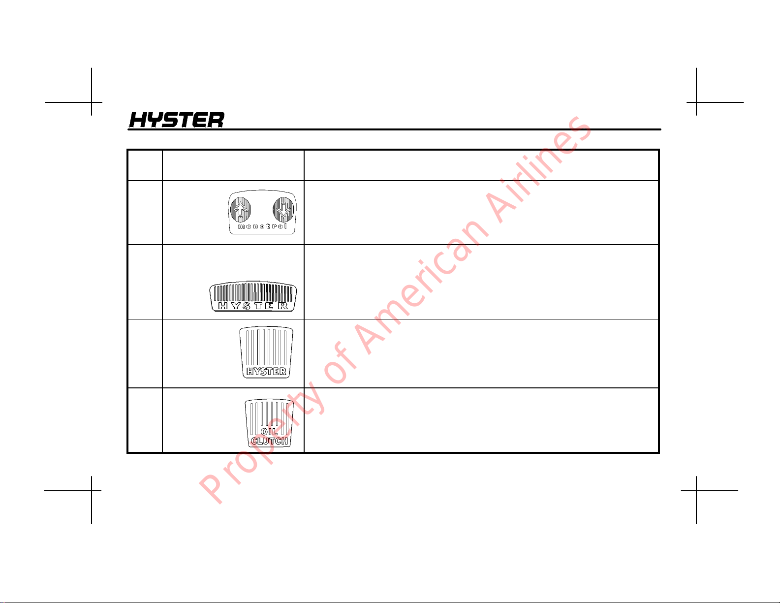
19 MONOTROL
Pedal
(Powershift
Transmission
Only)
20
Inching/Brake Pedal
(Powershift Transmission)
21
Brake Pedal
(Manual
Transmission)
(S135--155XL
Only)
22
Clutch Pedal
(Manual
Transmission)
(S135--155XL
Only)
ITEM FUNCTION
The MONOTROL pedal controls the speed and direction of the lift truck.
Pushing on the right side of the pedal causes the lift truck to move in
REVERSE. Pushing on the left side of the pedal causes the lift truck to move in
FORWARD. The speed of the engine increases as the pedal is depressed.
By varying the position of the inching/brake pedal, the operator can move the
lift truck slowly while a high engine speed is used for lifting loads. Completely
depressing the pedal disengages the transmission and applies the service
brakes. The engine can be started when the inching/brake pedal is fully
depressed.
This pedal, controlled by the operator’s right foot, controls the application of the
service brakes.
The clutch pedal is located to the left of the brake pedal. This pedal, controlled
by the operator’s left foot, controls clutch engagement for the transmission and
inching operations.
21
Property of American Airlines
MODEL DESCRIPTION
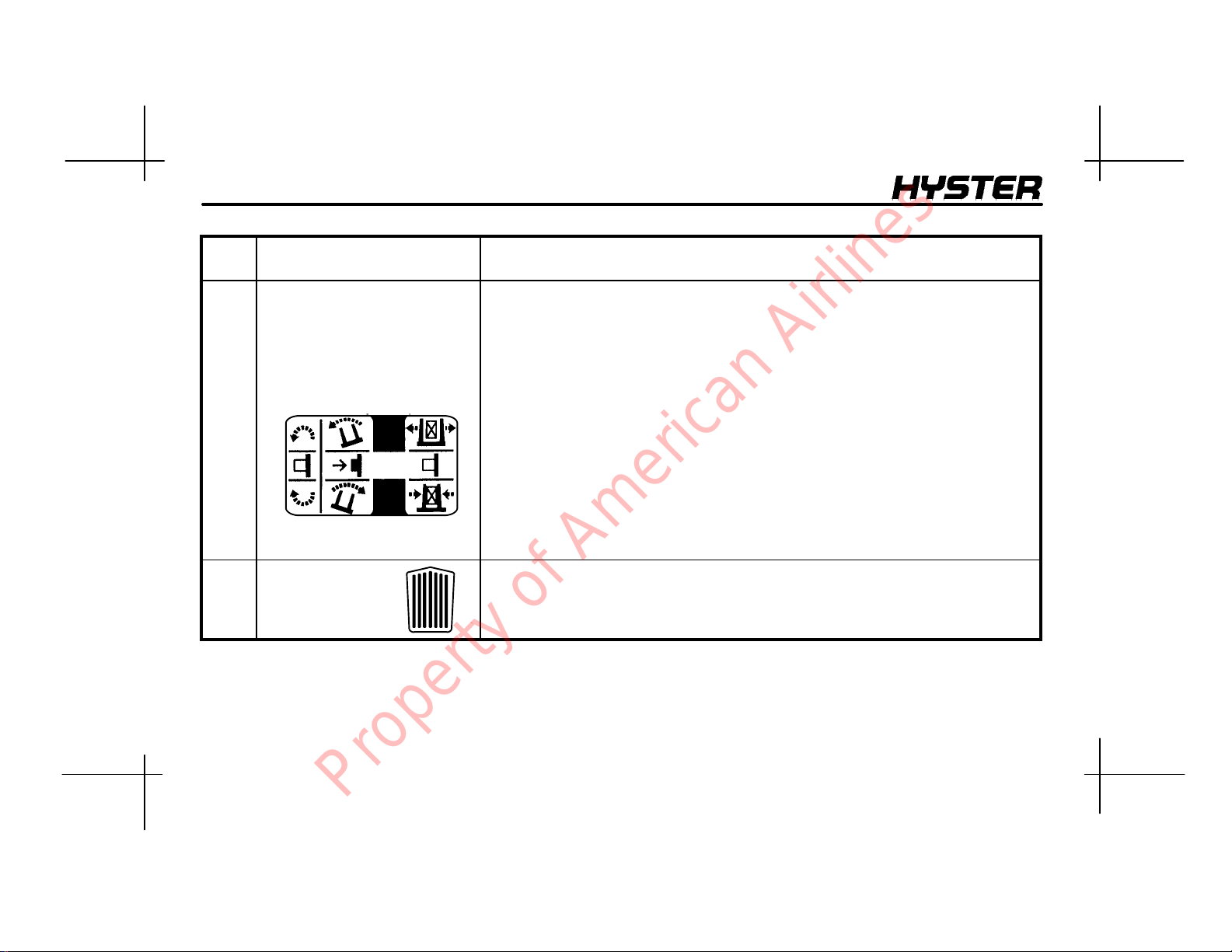
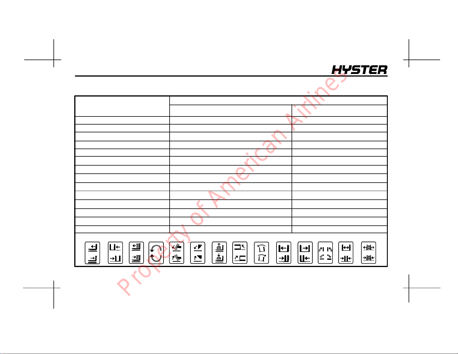
TABLE 3. AUXILIARY CONTROL LEVERS
FUNCTION
The control levers will be arranged in the
following order from left to right.
REACH Backward/Forward
1
2
SIDE SHIFT
3
PUSH -- PULL
ROTATE
4
UPENDER
5
6
SCOOP
LOAD STABILIZER
7
SWING (FORKS)
8
SWING (CLAMP)
9
L.H. FORK POSITIONER
10
R.H. FORK POSITIONER
11
TURN FORK
12
FORK SPREAD
13
14 CLAMP
LOAD OR EQUIPMENT CONTROL LEVER
Retract / Extend
Backward / Forward
Clockwise / Counterclockwise
Down (Clamp) / Up (Release)
Together / Apart
Together / Apart
Horizontal / Vertical
Together / Apart
Clamp / Release
DIRECTION OF MOVEMENT
Right / Left
Up / Down
Up / Down
Right / Left
Right / Left
Backward/Forward
Backward/Forward
Backward/Forward
Backward/Forward
Backward/Forward
Backward/Forward
Backward/Forward
Backward/Forward
Backward/Forward
Backward/Forward
Backward/Forward
Backward/Forward
Backward/Forward
1234567891011121314
12384
22
Property of American Airlines
OPERATING PROCEDURES
OPERATINGPROCEDURES
GENERAL
Know Your Lift Truck
The fork lift truck is designed to pick up and move materials.
The basic lift truck has a lift mechanism and forks on the
front to engage the load. The lift mechanism lifts the load so
that it can be moved and stacked.
In order to understand how the fork lift truck can pick up a
load, you must first know some basic things about the lift
truck.
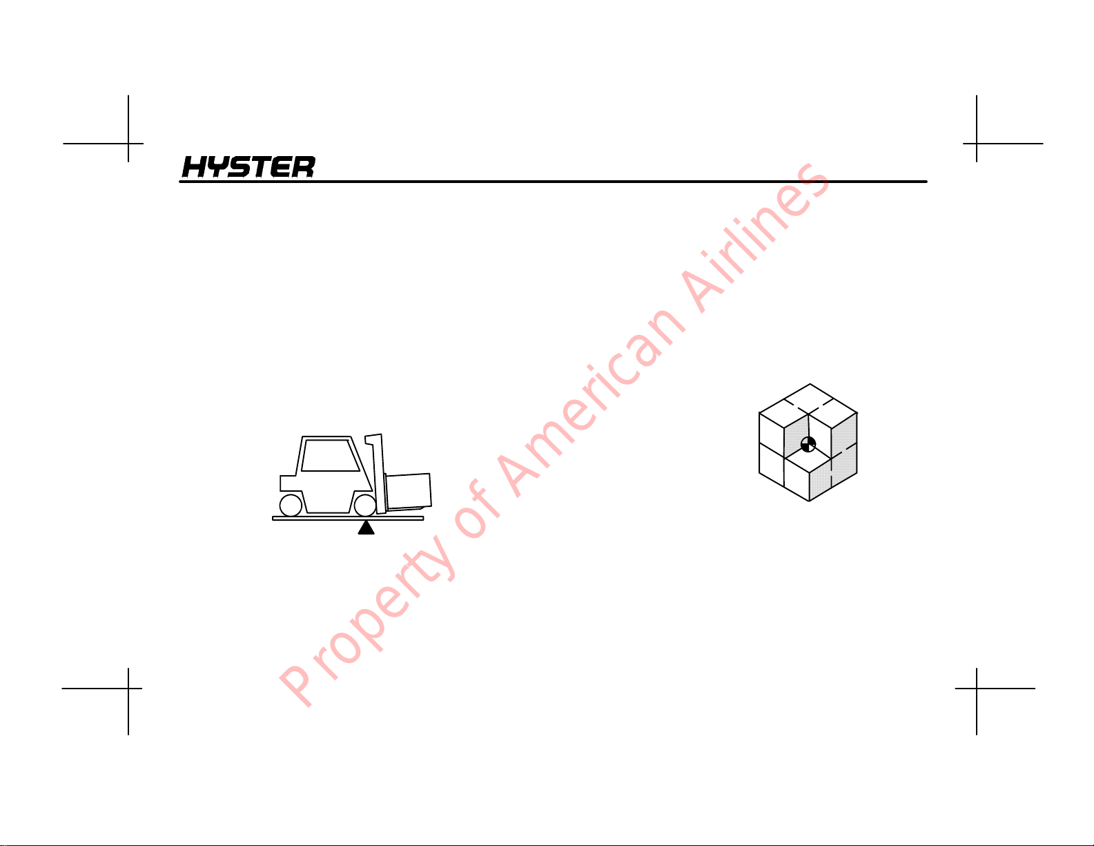
The lift truck is based on the principle of two weights balanced on opposite sides of a pivot (fulcrum). This is the
same principle used for a see--saw. In order for this princi-
ple to work for a lift truck, the load on the forks must be balanced by the weight of the lift truck. The location of the center of gravity of both the truck and the load is also a factor.
This basic principle is used for picking up a load. The ability
of the lift truck to handle a load is discussed in terms of center of gravity and both forward and side stability.
Stability and Center Of Gravity
The center of gravity (CG) of any object is the single
point about which
the object is balanced in all directions.
Every object has a CG. When the lift truck picks up a load,
the truck and load have a new combined CG.
The stability of the lift truck is determined by the location of
its CG, or if the truck is loaded, the combined CG.
23
Property of American Airlines
OPERATING PROCEDURES
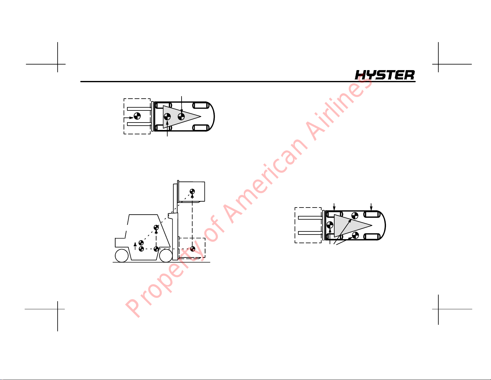
CG Truck
CG Load
Combined CG
The lift truck has moving parts and therefore has a CG that
moves. The CG moves forward and back as the mast is
tilted forward and back. The CG moves up and down as the
mast moves up and down.
CG Load
Combined CG
CG Truck
The center of gravity, and therefore the stability, of the
loaded lift truck is affected by a number of factors, such as
size, weight, shape, and position of the load; the height to
which the load is raised; the amount of forward and backward tilt; tire pressure; and the dynamic forces created
when the truck is moving. These dynamic forces are caused
by things like acceleration, braking, turning, and operating
on uneven surfaces or on an incline. These factors must be
considered when traveling with an unloaded truck, as well,
because an unloaded truck will tip over to the side eas-
ier than a loaded truck with its load in the lowered position.
In order for the lift truck to be stable (not tip over forward or
to the side) the CG must stay within the area of the lift the
truck represented by a triangle drawn between the drive
wheels and the pivot of the steering axle.
Drive Axle
CG - - Truck Will Tip Over
If the CG moves forward of the drive axle, the lift truck will
tip forward. If the CG moves outside of the line represented
by the lines drawn between the drive wheels and the steering axle pivot, the lift truck will tip to that side.
Steering Axle
24
Property of American Airlines
OPERATINGPROCEDURES
Capacity
(Weight and Load Center)
The capacity of the lift truck is shown on the Nameplate.
The capacity is listed in terms of weight and load center.
The weight is specified in kilograms and pounds. The load
center is specified in millimeters and inches. The capacity is
the maximum load that the lift truck can handle for the load
condition shown on the Nameplate.
The load center of a load is determined by the location of its
center of gravity . The load center is measured from the front
face of the forks, or the load face of an attachment, to the
center of gravity of the load. Both the vertical and horizontal
load centers are specified on the Nameplate.
For carriages or attachments that can be sideshifted, the
Nameplate specifies capacities in the “Centered” and “Sideshifted” conditions. Capacities listed under “Centered” on
the Nameplate apply when transporting loads that are centered on the centerline of the lift truck. Capacities listed under “Sideshifted” on the Nameplate apply if loads are transported that are not centered on the centerline of the lift
truck. Loads should be transported while centered on the
centerline of the lift truck.
The operator must know whether or not a load is within the
maximum capacity of the lift truck before the load is handled.
INSPECTION BEFORE
OPERATION
Checks With the
Engine Stopped
Inspect the lift truck before use and every eight hours or
daily as described in the MAINTENANCE section of this
OPERATING MANUAL.
Before using the lift truck, make the following checks:
• Fuel level (if the lift truck has a diesel engine, drain
water from the primary filter).
• Electrolyte level of the battery (unless maintenance
free).
25
Property of American Airlines
OPERATING PROCEDURES
• Oil level in the engine and hydraulic tank.
• Coolant level in the cooling system and condition of the
drive belts.
• Condition of the radiator. Clean if necessary.
• Condition of forks, carriage, chains, mast, attachment
and overhead guard.
• Leaks from the engine, transmission, hydraulic system
and fuel system.
• Condition of wheels and tires.
• Seat belt latches properly.
• Seat is correctly fastened to its mounts. Hood is securely
latched.
W ARNING
Report damage or faulty operation immediately. Do not
operate a damaged or defective lift truck. A lift truck
will only do its job when it is in proper working order. If
repairs are required, install a tag in the operator’s area
stating “DO NOT OPERATE” and remove the key from
the key switch.
Starting Procedures
Do not start nor
operate the lift
truck, including
any of its functions or attachments, from any
place other than
the designated
operator’s position.
Gasoline Or LPG Engine
W ARNING
LPG is very flammable. An odor of LPG fuel can indicate a leak in the fuel system. DO NOT start the engine
until the fuel leak is repaired.
1. If the lift truck uses LPG fuel, open the fuel valve on the
LPG tank.
2. Make sure the parking brake is applied or push on the
inching/brake pedal.
26
Property of American Airlines
OPERATINGPROCEDURES
3. If equipped, put the direction control lever for the trans-
mission in the NEUTRAL (N) position.
CAUTION
Do not engage the starter for more than 30 seconds at a
time. If the engine does not start, turn the key switch to
OFF. Wait 60 seconds before engaging the starter
again.
4. Turn the key to the START position to engage the starter.
5. If the engine does not start after four attempts, get help
from authorized service personnel.
6. When the engine is running, check the gauges and indi-
cator lights for the correct operation. See the Instruments
AndControlssectioninthisOPERATING MANUAL for a
description of the correct operation.
Diesel Engine
1. Make sure the parking brake is applied or push on the
inching/brake pedal.
2. If equipped, put the direction control lever for the trans-
mission in the NEUTRAL (N) position.
3. Turn the key to START to engage the starter. If the out-
side temperature is 7°C(45°F) or below, crank the engine
two revolutions to prime the fuel system. Turn the key to the
OFF position. Push the HEAT button and hold it for 20 to 25
seconds, then engage the starter again for 10 seconds.
CAUTION
Use only approved starting aids. Use of non--approved
starting aids can result in engine damage and void engine warranty.
4. If the engine does not start after four attempts, get help
from authorized service personnel.
5. When the engine is running, check the gauges and indicator lights for the correct operation. See the INSTRUMENTS AND CONTROLS section for a description of the
correct operation.
27
Property of American Airlines
OPERATING PROCEDURES
W ARNING
FASTEN YOUR
SEA T BELT!
The seat belt is installed to help the
operatorstay on the
truck if the lift truck
tips over. IT CAN
ONLY HELP IF IT IS
FASTENED.
Checks With the
Engine Running
The operator must be aware that the lift truck can tip over.
There is a great risk that the operator or someone else can
be killed or injured if trapped or hit by the truck as it tips
over. The risk of injury can be reduced if the operator stays
on the truck. If the truck tips over do not jump off.
The SEAT BELT AND HIP RESTRAINT BRACKET provide
a means to help the operator keep the head and torso substantially within the confines of the truck frame and overhead guard if a tipover occurs. This protection system is
intended to reduce the risk of the head and torso being
trapped between the truck and the ground, but it can not
protect the operator against all possible injury in a tipover.
Make sure that the area around the lift truck is clear before
starting the engine or making any operational checks. Be
careful when making the checks. If the lift truck is stationary
during a check, apply the parking brake and put the transmission in NEUTRAL. Proceed carefully.
Check the operation of the following functions as described
in the MAINTENANCE section.
• Check the operation of the horn, gauges and indicator
lights.
28
• Check the oil level in the transmission:
Property of American Airlines
 Loading...