

Hyster Narrow Aisle N30XMR3, Narrow Aisle N45XMR3, Narrow Aisle N25XMDR3, Narrow Aisle N30XMDR3, Narrow Aisle N40XMR3 Operating Manual
...
OPER
A
A
NARROW AISLE
N30--40XMR3, N25XMDR3 (C470)
N45XMR3, N30XMDR3 (G138)
TING MANU
N50XMA3 (C471)
L
DO NOT REMOVE THIS MANUAL
FROM THIS UNIT
1487036
12/05
Property of American Airlines
LIFT TRUCK MODEL SERIAL NUMBER
TRACTION MOTOR SERIAL NUMBER
HYDRAULIC PUMP MOTOR SERIAL NUMBER
STEERING GEAR MOTOR SERIAL NUMBER
LIFT HEIGHT GROUP NUMBER
DRIVE TIRE SIZE COMPOSITION
SPECIAL EQUIPMENT OR ATTACHMENTS
REGISTERED TRADEMARKS
Hyster,
SitDrive and StanDrive are registered trademarks of Hyster Company.
, SpaceSaver, Straddle Truck, Karry Krane, Yardmaster, Monotrol, OrderMaster, SpaceMaster, RACKLOADER,
Property of American Airlines
NARROW AISLE
FOREWORD
TO OWNERS, USERS, AND OPERATORS:
The safe and efficient operation of a lift truck requires
skill and alertness on the part of the operator. To develop
the skill required the operator must:
S receive training in the proper operation of this lift truck.
S understand the capabilities and limitations of the lift
truck.
S becomefamiliar with the constructionof the lift truck and
see that it is maintained in good condition.
S read and understand the warnings and operating
procedures contained in this manual.
Inaddition,aqualifiedperson,experiencedinlift truckoperation, must guide a new operator through several driving
and load handling operations before the new operator attempts to operate the lift truck alone.
It is theresponsibility of the employer tomake sure thatthe
operator can see, hear, and has the physical and mental
ability to operate the equipment safely.
Various laws and regulations require the employer to train
lift truck operators. These laws and regulations include:
Occupational Safety and Health Act (OSHA) (USA)
Canada Material Handling Regulations
NOTE: A comprehensive operator training program is
available from HYSTER COMPANY. For further details
contact your HYSTER lift truck dealer.
This Operating Manual is stored in the container on the
mast screen. Read and understand this manual before operating the lift truck. This is a permanent reference and
must be available for use at all times.
This Operating Manual contains information necessary for
theoperation andmaintenance of abasic fork lift truck. Optional equipment is sometimes installed that can change
some operating characteristics described in this manual.
Makesurethenecessary instructions are available and understood before operating the lift truck.
HYSTER COMPANY 2005 1487036 ENGLISH
1
Property of American Airlines
NARROW AISLE
FOREWORD
TO OWNERS, USERS, AND OPERATORS:
Some of the components and systems described in this
OPERATING MANUAL will NOT be installed on your unit.
If you have a question about any item described, contact
your dealer for HYSTER lift trucks.
Additional informationthat describes the safe operation
anduseoflifttrucks is available from the followingsources:
S Employment safety and health standards or regulations
(Examples: “Occupational Safety and Health Standards
(USA)”, “Canada Material Handling Regulations”.
S Safety codes and standards (Example: American
NationalStandard,ANSIB56.1,SafetyStandard forLow
Lift and High Lift Trucks).
S Publications from government safety agencies,
government insurers, private insurers and private
organizations (Example: Accident Prevention for
Industrial Operations from the National Safety Council).
S “Guide for Users of Industrial Lift Trucks” describes lift
truck safety, good maintenance practices, and training
2
programs. Available from your dealer for HYSTER lift
trucks. HYSTER part number 852930.
NOTE: HYSTER lift trucks are not intended for use on
public roads.
NOTE: Throughout this manual, the terms right, left,front
and rear relate to the viewpoint of an operator standing in
the operator’s compartment facing the forks.
NOTE: The following symbols and words indicate safety
information in this manual:
DANGER
Indicatesa condition which willcauseimmediateinjury or death.
WARNING
Indicates a condition that can cause injury
CAUTION
Indicates a condition that can cause property damage!
Property of American Airlines

TABLE OF CONTENTS
CONTENTS
FOREWORD 1..................................
MODEL DESCRIPTION 7.........................
NAMEPLATE 8...............................
OPERATING PROCEDURES 21....................
GENERAL 21..................................
Stability and Center of Gravity 21..............
CHECKS WITH THE KEY SWITCH OFF 24.......
CHECKS WITH THE KEY SWITCH ON 25........
OPERATING TECHNIQUES 25..................
Starting Sequence 27........................
Driving and Direction Changes 28.............
Steering (Turning) 28........................
Load Handling -- General 30..................
Lifting, Lowering and Tilting 30................
How to Engage and Disengage a Load 32......
Traveling 35................................
Highway Trucks, Railroad Cars and Docks 37...
MAINTENANCE 41...............................
GENERAL 41..................................
HOW TO MOVE A DISABLED LIFT TRUCK 42....
HowtoTowtheLiftTruck 42..................
How to put a Lift Truck on Blocks 43...........
MAINTENANCE PROCEDURES 50.................
CHECKS WITH THE KEY SWITCH OFF 50.......
Hydraulic System 50.........................
Forks 51...................................
Reach, Tilt and Sideshift 54...................
Articulation Stop Adjustment 54...............
Battery 55..................................
CHECKS WITH THE KEY SWITCH ON 56........
Gauges, Horn and Fuses 56..................
Control Levers and Pedals 56.................
Lift System Operation 56.....................
Brake 57...................................
HOW TO CHARGE THE BATTERY 58............
HOW TO CHANGE THE BATTERY 60............
Battery Removal 60..........................
Battery Installation 61........................
BATTERY SPECIFICATIONS 63.................
TIRES AND WHEELS 64.......................
Drive/steer tire 64...........................
Load Wheels 65.............................
Caster Wheels 66...........................
Tire and Wheel Sizes 66.....................
CHANGES TO THE OVERHEAD GUARD 67......
3
Property of American Airlines
CONTENTS
NOTES
4
Property of American Airlines
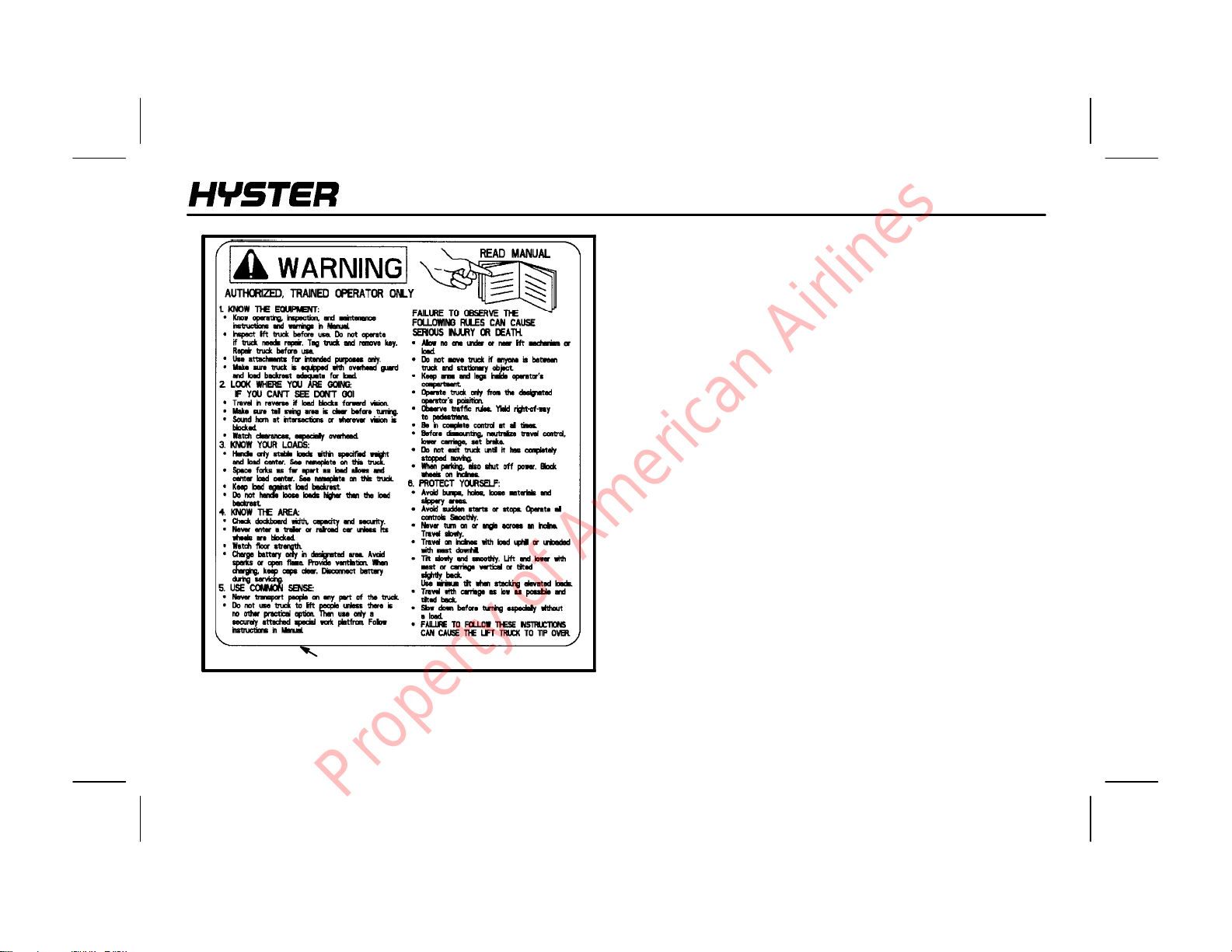
FAILURE TO OBSERVE THE FOLLOWING RULES CAN CAUSE SERIOUS INJURY OR DEATH!
KNOW THE EQUIPMENT:
NARROW AISLE
WARNING
WARNING
AUTHORIZED, TRAINED OPERAT OR ONLY!
KNOW YOUR LOADS:
S Know operating, inspection and maintenance instruc-
tions and warnings in Manual.
S Inspect truck before use. Do not operate if truck needs
repair. Tag truck and remove key. Repair truck before
use.
S Use attachments for intended purpose only.
S Make sure truck is equipped with overhead guard and
load backrest adequate for the load.
LOOKWHERE YOUARE GOING: IFYOUCAN’TSEE,
DON’T GO!
S Travel in reverse if load blocks forward vision.
S Make sure tailswing area is clear before turning.
S Sound horn at intersections or wherever vision is
blocked.
S Watch clearances, especially overhead.
Property of American Airlines
S Handle only stable loads within specifiedweight andload
center. See nameplate on this truck.
S Space forks as far apart as load allows and center load
between forks.
S Keep load against load backrest.
S Do not handle loose loads higher than load backrest.
KNOW THE AREA:
S Check dockboard width, capacity and security.
S Never enter a trailer or railroad car unless its wheels are
blocked.
S Watch floor strength.
S Charge battery only in designated area. Avoid sparks or
open flame. Provide ventilation. When charging, keep
vent caps clear. Disconnect battery during servicing.
5
WARNING
NARROW AISLE
USE COMMON SENSE:
S Never transport people on any part of the truck.
S Do not use truck to lift people unless there is no other
practical option. Then use only a securely attached
special work platform. Follow instructions in manual.
S Allow no one under or near lift mechanism or load.
S Do not move truck if anyone is between truck and
stationary object.
S Keep arms, legs, and head inside operator’s compart-
ment.
S Operate truck only from the designated operator’s
position.
S Obey traffic rules. Yield right-of-way to pedestrians.
S Be in complete control at all times.
S Before dismounting, neutralize travel control, lower
carriage, set brake. Do not exit truck until it has
completely stopped moving.
S When parking, also shut off power. Block wheels on
inclines.
PROTECT YOURSELF:
S Avoid bumps, holes, loosematerials, andslippery areas.
S Avoid sudden starts or stops. Operate all controls
smoothly.
S Never turn on or angle across an incline. Travel slowly.
S Travel on inclines with load uphill or unloaded with mast
downhill.
S Tilt slowly and smoothly. Lift and lower with mast or
carriage vertical or tilted slightly back. Use minimum tilt
when stacking elevated loads.
S Travel with carriage as low as possible and tilted back.
S Slow down before turning - especially without load.
S FAILURE TO FOLLOW THESE INSTRUCTIONS CAN
CAUSE THE LIFT TRUCK TO TIP OVER!
Although there is no sure way in all circumstances to avoid
injury, where possible, in the event of an imminent tipover
or off--the--dock accident, the operator should STEP OFF
AND AWAY FROM THE TRUCK. These actions are
intended to reduce the risk of serious injury or death.
6
Property of American Airlines
NARROW AISLE
MODEL DESCRIPTION
MODEL DESCRIPTION
This Operating Manual describes the operation and basic
maintenance of the HYSTER Narrow Aisle N30XMR3,
N40XMR3, N45XMR3 (reach), N25XMDR3, N30XMDR3
(double reach) and N50XMA3 (straddle) lift trucks. The lift
trucks are available with 24 volt or 36 volt systems,
depending upon the model selected. These battery
powered lift trucks have lifting capacities of1,134 to 2,268
kg(2,500to5,000lb)ata610mm(24inch)loadcenterand
are available with two or three stage masts.
These trucks feature a SEM (Separately Excited Motor)
traction control system as well as neutral braking. The
controller has diagnostic capabilities and thermal
protection. Travel acceleration, top speed and operator
drive modes are set through the traction controller.
Proportional plugging is standard.
Amulti-functioncontrolhandleprovidescontrolof direction,
lift/lower,extend/retract, tilt and optionalsideshift. The horn
button is also on the side of the control handle.
The instrument display includes a battery discharge
indicator with lift interrupt, hourmeters, LED function
selection lights, operator selectable drive modes for speed
of tractionand an LCD display which provides the status of
systems and fault messages in English, not in numerical
codes.
All lift trucks have operator protection equipment. The
overhead guard is intended to offer reasonable protection
to the operator from falling objects, but cannot protect
against every possible impact. Therefore, it must not be
considered a substitute for good judgement and care when
handling loads. A rear overhead guard leg provides
protection for the operator and unobstructed operation of
the lift truck. A fullheight wire mast guardismounted to the
rearofthemast.Donot remove anyequipmentprovidedfor
the protection of the operator.
The battery compartment must have spacers to prevent
horizontal movement of more than 13 mm (0.5 in). The
battery restraintpanelsmustbeinplacebeforethe lift truck
is operated. The battery can be removed from either side
of the lift truck, although right side removal is preferred to
avoid damage to the battery cables. A roller rack under the
battery permitseasybatterymovement. For correct battery
sizes, see the Battery Specifications in the Maintenance
Section.
7
Property of American Airlines
NARROW AISLE
MODEL DESCRIPTION
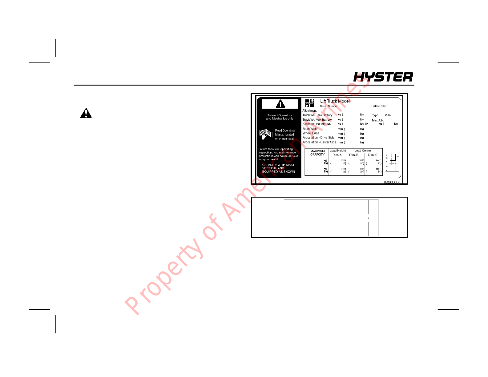
NAMEPLATE
WARNING
Any change to the lift truck, the tires or its equipment
can change the lifting capacity. If the nameplate does
not show the maximum capacity , or if the lift truck
equipment,includingthe battery,doesnot match that
shown on the nameplate, then the lift truck must not
be operated.
The lift truck nameplate is located inside the operator’s
compartment. The shown is for a lift truck equipped as
shown on the nameplate. The capacity is specified in
kilograms (kg), and pounds (lb). The capacity is the
maximumloadthelifttruckcanhandle fortheloadcondition
shown on the nameplate.
The maximum capacity for the lift truck must be shown on
the nameplate. If the lift truck nameplate already has a
capacity for special load handling equipment, it will be
listed. Make sure the nameplate data is complete and fully
understood before operating the lift truck.
The lift truck serial code number is on the nameplate. The
serial code number is also stamped on the lift truck frame.
FIGURE 1. NAMEPLATE
NOTICE TO USER
The U.S.A. Occupational Safety and Health
Act of 1970 and other national safety codes
require anew plate if this unit is equipped
other thanas stated on plate. Obtain the
correct plate from your authorized dealer.
FIGURE 2. DECAL
When a unit is shipped incomplete from the factory to the
dealer, the nameplate is covered by a label as shown in
FIGURE 2. If your lift truck has this type of label, do not
operate the lift truck. Contact your dealer for HYSTER lift
trucks to obtain a complete nameplate.
To remove pull here
8
Property of American Airlines
NARROW AISLE
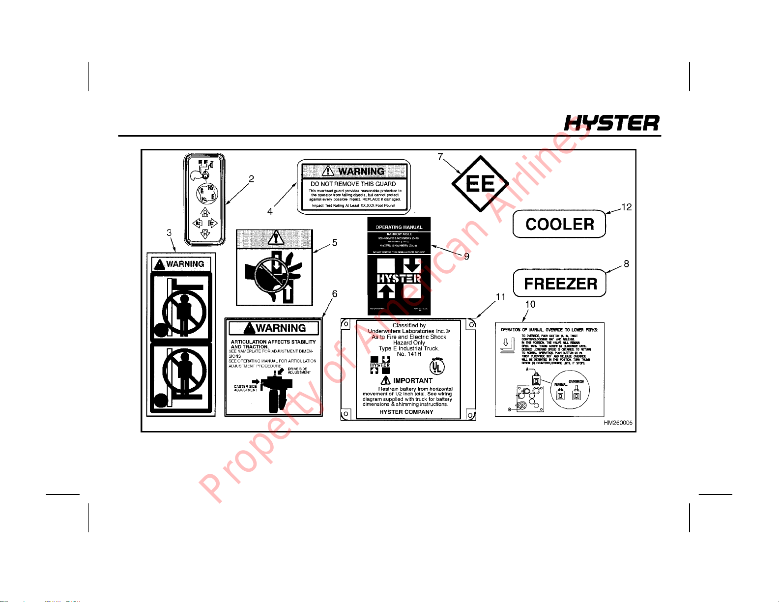
WARNING LABELS (FIGURE 3. & FIGURE 4.)
11. Label, Operator Warning
12. Label, Multi--Function Handle
13. Label, Fork Warning
14. Label, Overhead Guard
15. Label, Pinch Points
16. Label, Articulation
17. Label, Identification EE
MODEL DESCRIPTION
1
FIGURE 3. WARNING LABELS
NA02230
Property of American Airlines
18. Label, Freezer Identification
19. Operating Manual
10. Label, Manual Lowering
1 1. Label, Underwriters Laboratory
12. Label, Cooler Identification
9
MODEL DESCRIPTION
NARROW AISLE
10
FIGURE 4. WARNING LABELS
Property of American Airlines
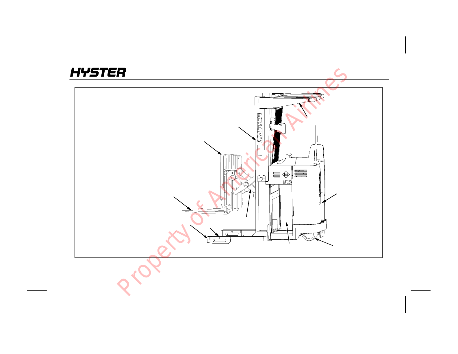
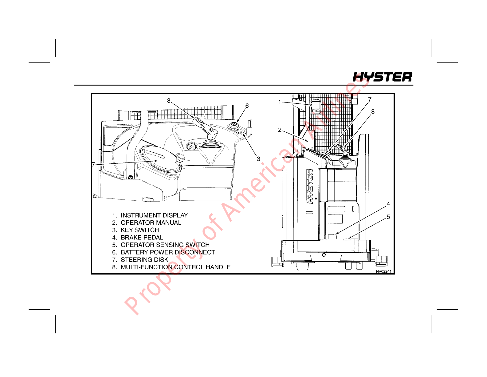
Major Components of the Lift Truck
1. Overhead Guard
2. Mast
3. Load Backrest
4. Forks
5. Basearms
6. Battery Compartment
7. Drive/Steer Wheel
8. Load Wheels
9. Operator’s Compartment
10. Carriage
NARROW AISLE
MODEL DESCRIPTION
1
2
3
4
5
FIGURE 5. MAJOR COMPONENTS OF THE LIFT TRUCK
8
10
6
9
7
11
Property of American Airlines
MODEL DESCRIPTION
NARROW AISLE
12
FIGURE 6. INSTRUMENTS AND CONTROLS
Property of American Airlines
NARROW AISLE
MODEL DESCRIPTION
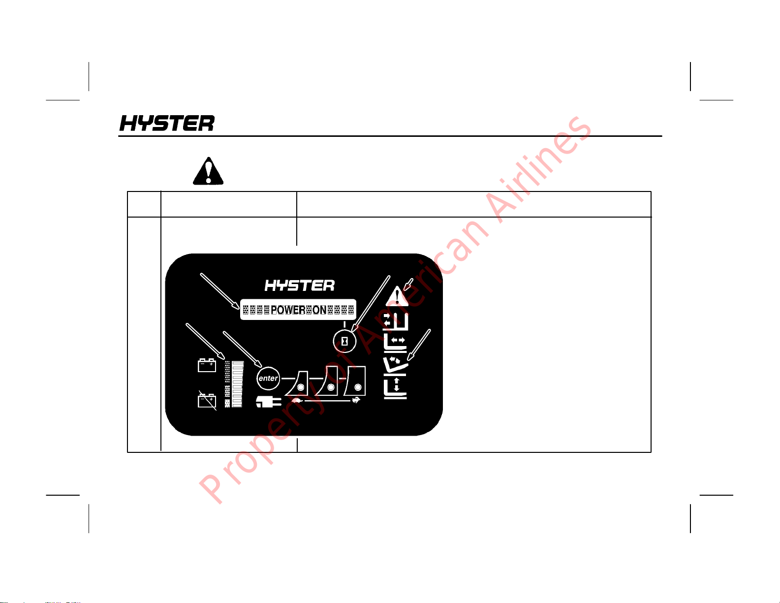
TABLE 1. INSTRUMENTS AND CONTROLS
WARNING: If any of the instruments or controls do not operate as described in this table,
report the problem immediately. DO NOT operate the lift truck until the problem is corrected.
ITEM
NO.
1
ITEM
Instrument Display
a
c
d
FUNCTION
The instrument display is mounted on a bracket at eye level in the
operator’s compartment and has the following features:
a. Message Center
e
f
b. Function Selection Lights
c. Battery Indicator
d. Drive Mode Feature
e. Hourmeter
f. Warning Lights
b
The instrument display is powered even
when the vehicle is not being operated.
When the battery is disconnected, the
dashboard contains an internal back-up
battery, capable of memory retention of
the battery indicator and hourmeter.
13
Property of American Airlines
MODEL DESCRIPTION
NARROW AISLE
ITEM
NO.
a
b
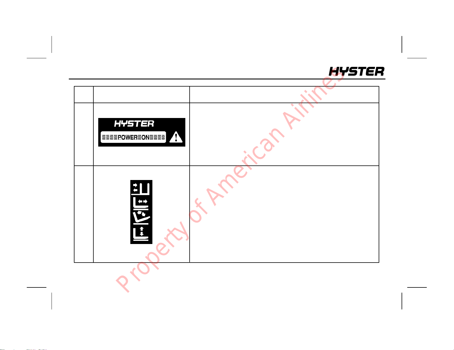
ITEM FUNCTION
Message Center
LCD indicators
Function Selection Lights
LEDindicators
The Message Center is a 16 character, dot matrix LCD (Liquid Crystal
Display)withgreenbacklighting.The16character,alpha-numericdisplay
showsthehourmeter readings, lift truckperformancestatus, andwarning
or fault conditions in English. When a warning message is received, the
warning/fault indicator will blink as a yellow light. When a fault message
is received, the warning/fault indicator will blink as a red light.
TheFunction SelectionLightsdisplay the selected hydraulic function.
Status messages will be displayed for LIFT, REACH, TILT AND
SIDESHIFT.Thefunctionselectionlightswill display the current hydraulic
function, independent of the present LCD display.
14
Property of American Airlines
NARROW AISLE
MODEL DESCRIPTION
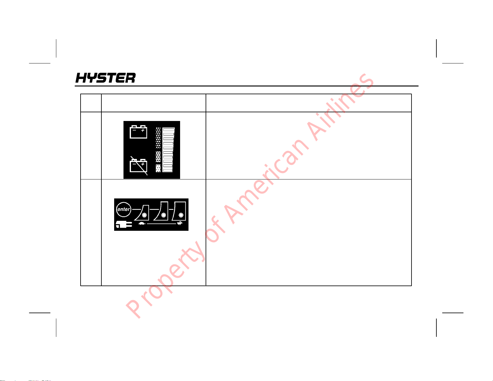
ITEM
NO.
c
d
ITEM FUNCTION
Battery Indicator
Drive Mode Display
TheBattery Indicatorhasa10barmulticolor LED (Light Emitting Diode)
to indicate battery charge status. The bars are green, yellow and red. As
battery power is used, the LED lightbarsturnOFF,firstgreen,thenyellow,
then red. The next to bottom red bar will flash indicating a nearly
discharged battery.At empty, the bottom red bar will alternately flashwith
the LO-BA TT indicator LED (a crossed battery symbol). The lift function
will be locked out at this point. Continued operation with a discharged
battery can damage the battery, motors or the contactors.
The Drive Mode Display allows the operator to select the traction motor
controller speed most suited to the application. Operation of the drive
mode switch will cause the green indicators and corresponding drive
modes to increase from Turtle to Mid to Rabbit. Turtle mode provides
slower acceleration and reduced top speed. It is also a valuable setting
when training new operators or on wet floorsfor better traction. Mid mode
reduces acceleration with full travel speed. Rabbit mode provides
maximum acceleration and travel speed. When the key switch is turned
to OFF, the selected drive mode is retained. When the battery is
disconnected the drive mode returns to the Rabbit mode. The rates of
acceleration and travelspeedsare programmable and can be adjusted by
a qualified service technician. The drive mode can only be selected while
in neutral.
15
Property of American Airlines
MODEL DESCRIPTION
NARROW AISLE
ITEM
NO.
e
2
ITEM FUNCTION
Hourmeter
Operating Manual
The Hourmeter switch is controlled by the operator and is used for
on-demanddisplayofhourmeterinformation. The hourmeter data canbe
displayed at any time by pressing the hourmeter switch. The switch is
marked with anhourglasssymbol. Press the switch once to display truck
hours to 1/10 of an hour. Presstwice todisplay drive motor hours. Press
three times to display the lift motor hours. Press four times to return to
the normal display mode. If the hourmeter is left in any of the first three
positions, the display will return to the normal display mode, which
indicates the current operational status of the lift truck after 30 seconds.
The Operating Manual is sent with the lift truck and is located in the
container on the wire mast guard mounted behind the mast. The
OperatingManualisapermanentreference andmustbeavailableforthe
operator’s use at all times. Read and understand this manual before
operating the lift truck.
16
Property of American Airlines
NARROW AISLE
MODEL DESCRIPTION
ITEM
NO.
3
4, 5
ITEM FUNCTION
Key Switch
Brake Pedal and
Operator Sensing Switch
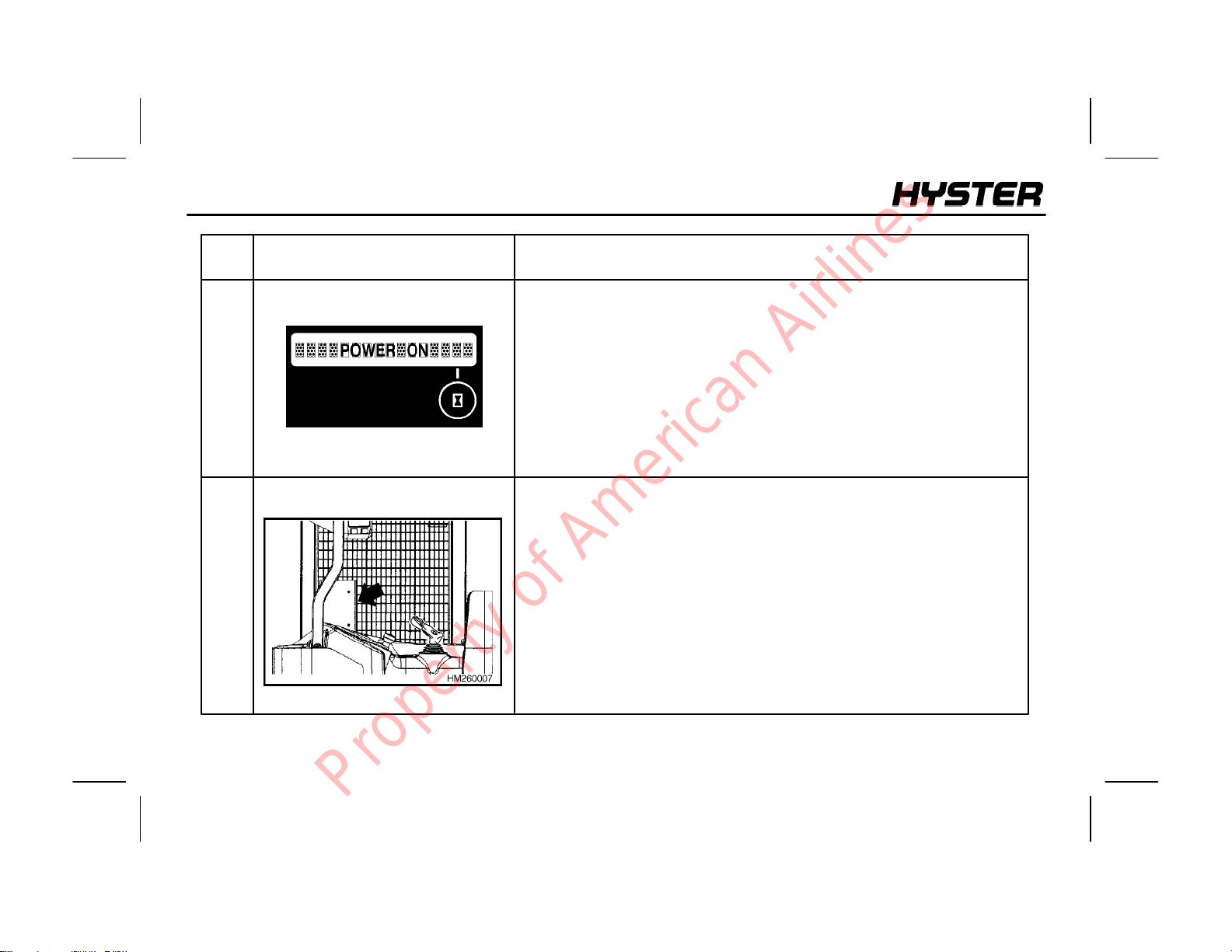
The key switchis a three position switch. The first positionis OFF(marked
O). The second position is RUN (marked I). The thirdposition is unmarked
and not used. It is spring loaded and automatically returns the key to the
RUNpositionafter thekeyisreleased.Thekeyswitchislocatedtotheright
side of the battery power disconnect knob.
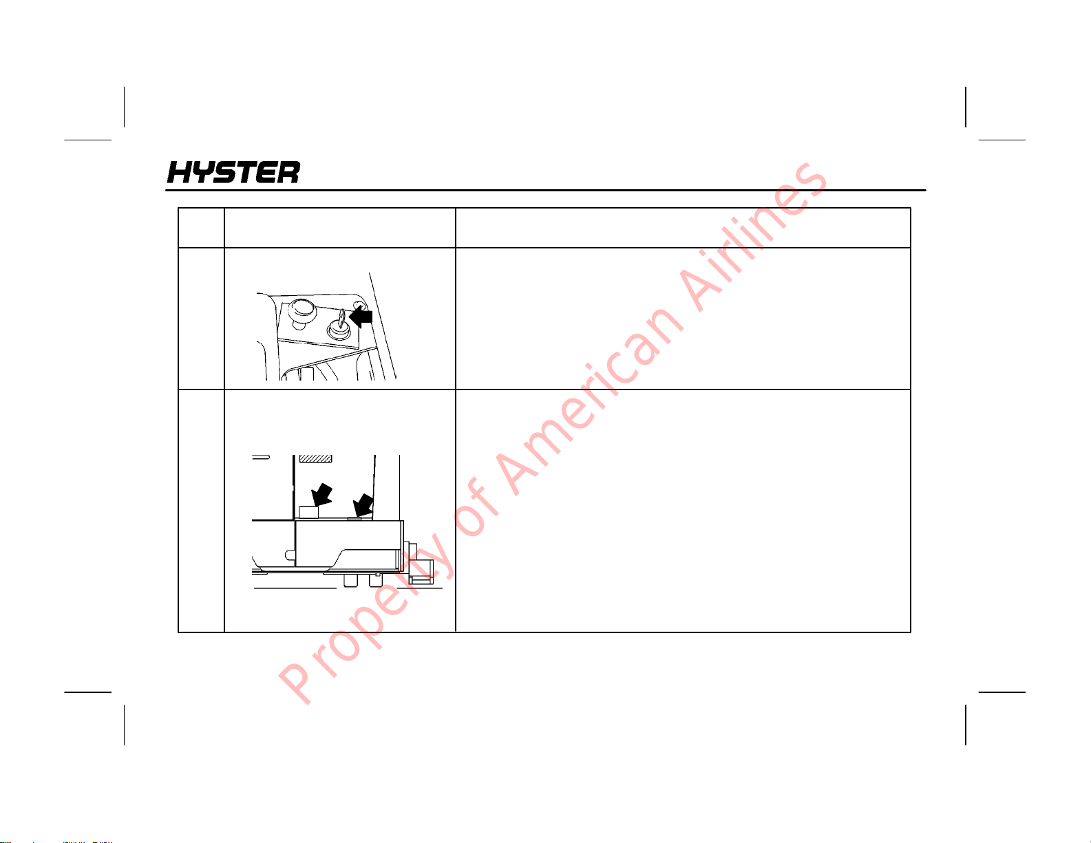
The brake is designed for both service and parking brake use. The brake
is spring applied and hydraulically released. The push down brake pedal
is on the floor in the rear of the operator’s compartment. The brake is
automatically applied when the brake pedal is released.
An operator sensing switch is on the floor to the right of the brake pedal
and must be closed with the brake pedal switch before lift truck operation
ispermitted. The operator must stepinto the operator’scompartment and
close both switches before driving or operating any hydraulics. When the
operator leaves the lift truck the parking brake is automatically applied.
17
Property of American Airlines
MODEL DESCRIPTION
NARROW AISLE
ITEM
NO.
6
7
ITEM FUNCTION
Battery Power Disconnect
Steering Disk
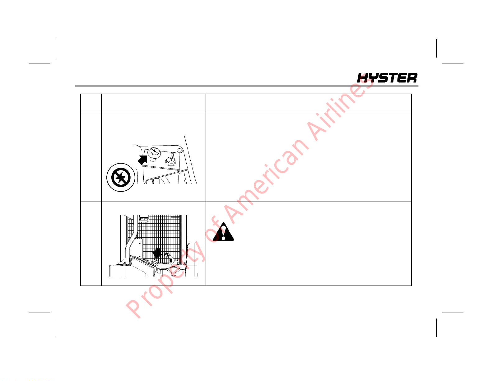
Theredbattery power disconnect switchislocatednexttothe key switch.
When pressed, power is shut off to all circuits in the lift truck. Power is
restored to the lift truck by pulling the switch upward.
The steering disk controls lift truck direction with 4 turns lock to lock.
WARNING: Reversesteeringisavailableforthis lift truck.
The operator should check the steering direction before
operating the lift truck.
18
Property of American Airlines
NARROW AISLE
MODEL DESCRIPTION
ITEM
NO.
8
ITEM FUNCTION
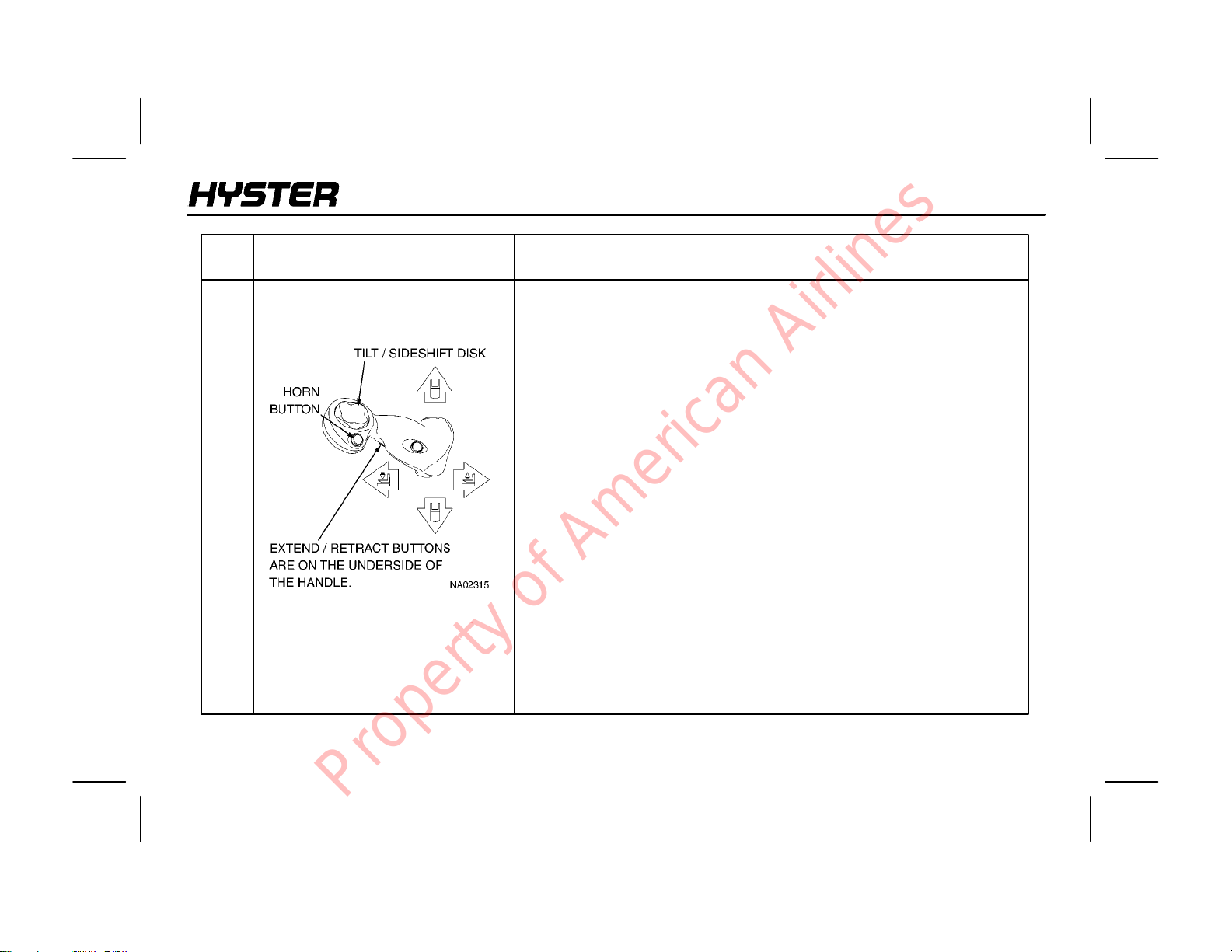
Multi-function Control Handle
The multi-function control handle allows the operator tocontrol travel, lift,
lower,tilt, sideshift, horn, and extend and retract functions. Eachfunction
has an independent control device.
Travel is activated by tilting the entire control handle in the direction of
travel. Pushing the control handle toward the forks makes the lift truck
travel forward. To change direction, move themulti-functionhandleinthe
oppositedirectionthelifttruckistraveling,regardless oftravelspeed.The
lift truck will come to a stop, then accelerateintheoppositedirection.This
control is proportional; therefore, the fartherthe control handle is pushed,
the faster the lift truck will accelerate or decelerate. If the multi-function
handle is released, it will return to neutral, and the truck will decelerate at
aprogrammedratetoastop.
The multi-function handle controls the direction and speed at which the
carriage moves vertically on the mast. Lift/Lower is activated by tilting
the entire control handle toward the left or right side of the lift truck. If the
control handle is tilted toward the right, the carriage lifts; if the control
handle is tilted toward the left, the carriage lowers. The farther the lever
is tilted, the faster the carriage lifts or lowers.
TheHorn button is located on the side of the multi-function handle facing
the operator, just to the left of the tilt/sideshift disk. The horn is activated
by pressing the button with the thumb.
19
Property of American Airlines
MODEL DESCRIPTION
NARROW AISLE
ITEM
NO.
8
ITEM FUNCTION
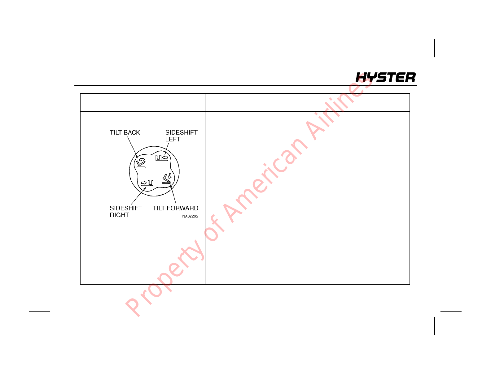
Tilt/Sideshift Disk
The Tilt/Sideshift Disk, located at the top of the multi-function handle
lever, controls the tilting and side--shifting of the carriage. The disk is
operated with the thumb of the right hand. To tilt the carriage forward,
press the top of the disk. To tilt the carriage back, press the bottom of the
disk. On lift trucksequippedwithasideshifting carriage, press the left side
of the disk to move the carriage to the left, and press the right side of the
disk to move the carriage to the right. Tilt and sideshift are single speed
functions.
The Extend and Retract buttons are located on the shaft of the
multi-function handle. Press the top button to provide low speed extend.
While the top button is still actuated, press the bottom button to provide
high speed extend. Press the bottom button to provide low speed retract.
While the bottom button is still actuated, press the top button to provide
high speed retract.
Themulti-function handleiscapableofprovidingvariabletraction,variable
lift or lower, a single auxiliary function and the horn simultaneously for
improved productivity.
20
Property of American Airlines
 Loading...