

Hyster J30XNT, K160, J35XNT, J40XNT Operating Manual

OPERATING MANUAL
J30-40XNT (K160)
Property of American Airlines
DO NOT REMOVE THIS MANUAL FROM THIS UNIT
PART NO. 1676236 2/17

Spacer
LIFT TRUCK MODEL
TRACTION MOTOR
HYDRAULIC PUMP MOTOR
STEERING PUMP MOTOR
MAST LIFT HEIGHT
CARRIAGE TYPE
DRIVE TIRE SIZE
SPECIAL EQUIPMENT OR ATTACHMENTS
© Hyster Company 2017. All Rights Reserved.
HYSTER,
are Trademarks in the United States and certain other jurisdictions.
, FORTIS, MONOTROL, and YARDMASTER are Registered Trademarks of Hyster-Yale Group, Inc. HSS, DURAMATCH, UNISOURCE, and
SERIAL NUMBER
SERIAL NUMBER
SERIAL NUMBER
SERIAL NUMBER
GROUP NUMBER
GROUP NUMBER
STEERING TIRE SIZE

Foreword
Foreword
To OWNERS, USERS, and OPERATORS:
The safe and efficient operation of a lift truck requires
skill and alertness on the part of the operator. To develop
the skill required, the operator must:
• Receive training, pursuant to OSHA 1910.178(l) dated
12/98, in the proper operation of THIS lift truck.
• Understand the capabilities and limitations of the lift
truck.
• Become familiar with the construction of the lift truck and
see that it is maintained in good condition.
• Read and properly understand the warnings, instructions, and operating procedures in this manual.
In addition, a qualified person, experienced in lift truck
operation, must guide a new operator through several driving and load handling operations before the new operator
attempts to operate the lift truck alone.
It is the responsibility of the employer to make sure that the
operator can see, hear, and has the physical and mental
ability to operate the equipment safely.
©HYSTER COMPANY 2017 1676236 - ENGLISH-US 1
Various laws and regulations require the employer to train
lift truck operators. These laws and regulations include:
• Occupational Safety and Health Act (OSHA) (USA)
• Canada Material Handling Regulations
NOTE: A comprehensive operator training program is avail-
able from Hyster Company. For further details, contact
your dealer for Hyster lift trucks.
This Operating Manual is the original instruction and contains information necessary for the operation and maintenance of a basic fork lift truck. Optional equipment is
sometimes installed that can change some operating characteristics described in this manual. Make sure the necessary instructions are available and understood before
operating the lift truck.
Some of the components and systems described in this
Operating Manual will NOT be installed on your unit. If you
have a question about any item described, contact your
dealer for Hyster lift trucks.

Foreword
Additional information that describes the safe operation
and use of lift trucks is available from the following sources:
• Employment safety and health standards or regulations
(Examples: "Occupational Safety and Health Standards
(USA)," "Canada Material Handling Regulations."
• Safety codes and standards (Example: Industrial Truck
Standards Development Foundation, ANSI/ITSDF
B56.1, Safety Standard for Low Lift and High Lift
Trucks).
• Publications from government safety agencies, government insurers, private insurers, and private organizations
(Example: Accident Prevention Manual For Industrial
Operations, from the National Safety Council).
• Guide for Users of Industrial Lift Trucks (Hyster Part No.
852930) describes lift truck safety, good maintenance
practices, and training programs and is available from
your dealer for Hyster lift trucks.
NOTE: Hyster lift trucks are not intended for use on public
roads.
NOTE: The following symbols and words indicate safety
information in this manual:
WARNING
Indicates a hazardous situation which, if not avoided,
could result in death or serious injury.
CAUTION
Indicates a hazardous situation which, if not avoided,
could result in minor or moderate injury and property
damage.
On the lift truck, the WARNING symbol and word are on
orange background. The CAUTION symbol and word
are on yellow background.
2

Contents
Foreword ...................................................................... 1
TO OWNERS, USERS, AND OPERATORS: ............. 1
Warning ........................................................................ 7
Model Description ....................................................... 10
GENERAL ................................................................... 11
OPERATOR PROTECTION EQUIPMENT ................. 18
NAMEPLATE .............................................................. 19
SAFETY LABELS ....................................................... 20
OPERATOR CONTROLS ........................................... 24
Display Panel Features ............................................... 55
DISPLAY PANEL ........................................................ 55
DISPLAY PANEL KEYS ............................................. 56
DISPLAY PANEL - LCD SCREEN AND WARNING
AND INDICATOR LIGHTS ....................................... 64
NORMAL SEQUENCE OF OPERATION - DISPLAY
PANEL ...................................................................... 76
NORMAL SEQUENCE OF OPERATION - DISPLAY
PANEL WITH OPTIONS ........................................... 77
Operating Procedures ................................................ 79
GENERAL ................................................................... 79
Know Your Lift Truck ................................................ 79
Stability and Center of Gravity .................................. 80
Capacity (Weight and Load Center) ......................... 81
Contents
Impact Sensor ........................................................... 82
INSPECTION BEFORE OPERATION ........................ 83
Checks With the Key or Keyless Switch OFF ........... 83
Operator Passwords ................................................. 84
Operator Checklist .................................................... 86
Mounting and Dismounting ....................................... 89
Start-Up Procedure - SRO Circuit ............................. 89
Lift Trucks with Software Versions Less than 4.32 . 89
Lift Trucks with Software Versions 4.32 and
Greater ............................................................. 90
Lift Truck Interlocks ................................................... 92
Checks With the Key or Keyless Switch ON ............. 100
Load Weighing Sensor ............................................. 101
Set Load Weight to Zero ........................................... 103
OPERATING TECHNIQUES ...................................... 104
Basic Operating Procedures ..................................... 105
Driving and Direction Changes ................................. 109
Steering (Turning) ..................................................... 110
Synchronized Steering Control ................................. 112
Auto Power Off ......................................................... 112
Standard Operator Presence System ....................... 113
Lift Trucks with Software Versions Less than 4.32 . 113
3

Contents
Lift Trucks with Software Versions 4.32 and
Greater ............................................................. 113
Optional Operator Presence System ........................ 114
Lift Trucks with Software Versions 4.32 and
Greater ............................................................. 114
Automatic Parking Brake .......................................... 115
Load Handling - General ........................................... 117
Lifting, Lowering, and Tilting ..................................... 118
How to Engage and Disengage a Load .................... 121
Load Handling, Traveling .......................................... 124
Load Handling, Emergency Load Lowering .............. 127
Manual Main Control Valve ..................................... 127
E-Hydraulic Main Control Valve .............................. 129
HIGHWAY TRUCK, RAILROAD CARS, AND
DOCKS ..................................................................... 131
ATTACHMENTS ......................................................... 132
STOPPING ................................................................. 133
PARKING .................................................................... 133
Maintenance ................................................................ 134
GENERAL ................................................................... 134
SERIAL NUMBER DATA ............................................ 135
HOW TO MOVE A DISABLED LIFT TRUCK .............. 136
How to Tow the Lift Truck ......................................... 137
HOW TO PUT A LIFT TRUCK ON BLOCKS .............. 139
How to Raise the Drive Tires .................................... 139
How to Raise the Steer Tire ...................................... 140
HOW TO CLEAN A LIFT TRUCK ............................... 142
Maintenance Schedule ............................................... 142
Maintenance Procedures Every 8 Hours or Daily .... 156
HOW TO MAKE CHECKS WITH THE KEY OR
KEYLESS SWITCH OFF .......................................... 156
Wheels and Tires ...................................................... 156
Safety Labels ............................................................ 157
Frame and Covers .................................................... 158
Forks, General .......................................................... 160
Forks, Remove ......................................................... 160
Forks, Inspect ........................................................... 165
Forks, Install ............................................................. 166
Forks, Adjust ............................................................. 167
Inspection of Mast, Carriage, Header Hoses, Lift
Chains, and Attachments ...................................... 167
Hydraulic Oil Level and Leaks .................................. 170
Operator Restraint System ....................................... 170
Emergency Locking Retractor (ELR) ........................ 174
Battery Restraint System .......................................... 175
Lift Trucks Manufactured Before November, 2014 . 178
Lift Trucks Manufactured After November, 2014 .... 178
Steering Column Adjustments .................................. 182
Tilt Adjust Feature ................................................... 183
Tilt Memory Feature ................................................ 183
4

Contents
Telescopic Feature ................................................. 183
Battery Check ........................................................... 184
HOW TO MAKE CHECKS WITH THE KEY OR
KEYLESS SWITCH ON ............................................ 185
Control Levers and Pedals ....................................... 185
Direction and Speed Control Pedals ......................... 185
Electrical Components .............................................. 185
Steering System ....................................................... 187
Hydraulic System ...................................................... 188
Service Brakes .......................................................... 189
Automatic Parking Brake .......................................... 189
Operator Presence System ...................................... 189
Oil Leaks ................................................................... 190
HOW TO CHARGE THE BATTERY ........................... 190
HOW TO CHANGE THE BATTERIES ........................ 193
General ..................................................................... 193
Remove the Battery .................................................. 193
Install the Battery ...................................................... 195
Optional Side Removal of Battery ............................. 197
BATTERY SPECIFICATIONS .................................... 200
WHEELS AND TIRES ................................................. 202
General ..................................................................... 202
PNEUMATIC TIRE REPAIR ....................................... 204
Remove Wheels From Lift Truck .............................. 204
Remove Tire From Wheel ......................................... 204
Tire Removal, Two-Piece Wheel ............................ 205
Tire Removal, Three- and Four-Piece Wheels ....... 206
Install the Wheel in the Tire ...................................... 207
Install Wheel in Tire, Three- or Four-Piece Wheel .. 208
Install Wheel in Tire, Two-Piece Wheel .................. 209
Add Air to the Tires ................................................... 210
Install the Wheels ..................................................... 211
SOLID RUBBER TIRES REPAIR ............................... 211
Change Solid Rubber Tires on Pneumatic Wheels .. 211
Remove Wheels From Lift Truck .............................. 211
Remove Tire From Wheel ......................................... 211
Install Tire on Wheel ................................................. 213
Install the Wheels ..................................................... 214
SOLID RUBBER (CUSHIONED) TIRES REPAIR ...... 215
Remove Wheels From Lift Truck .............................. 215
Remove and Install Tire on Wheel ............................ 215
HOW TO PUT AN ELECTRIC SIT DOWN RIDER
TRUCK IN STORAGE .............................................. 217
HOW TO PUT BATTERIES IN STORAGE ................. 218
HOW TO PUT A LIFT TRUCK BACK INTO
SERVICE .................................................................. 219
HOW TO MOVE A LIFT TRUCK ON A
TRANSPORT ............................................................ 219
Loading ..................................................................... 220
Unloading .................................................................. 220
5

Contents
PREPARATION FOR USE ......................................... 221
Preparation After Transport ...................................... 221
CHANGES TO THE OVERHEAD GUARD ................. 221
6

WARNING
FAILURE TO FOLLOW THESE INSTRUCTIONS CAN CAUSE SERIOUS INJURY OR DEATH!
AUTHORIZED, TRAINED OPERATOR ONLY!
The following WARNING is a label and must be on the
lift truck.
KNOW THE EQUIPMENT:
• KNOW operating, inspection, and maintenance instruc-
tions in Operating Manual.
• DO NOT operate or repair truck unless trained and
authorized.
• INSPECT truck before use.
• DO NOT operate if truck needs repair. Tag truck and
remove key. Repair truck before use. Always use Hyster
Approved parts when making repairs. Replacement
parts must meet or exceed the specifications of the original equipment manufacturer.
• USE attachments for intended purpose only.
• MAKE SURE truck is equipped with overhead guard and
load backrest adequate for the load.
Warning
LOOK WHERE YOU ARE GOING:
• IF YOU CAN'T SEE, DON'T GO.
• TRAVEL in reverse if load blocks forward vision.
• MAKE SURE tail swing area is clear before turning.
• SOUND horn at intersections or whenever vision is
blocked.
• WATCH clearances, especially overhead.
KNOW YOUR LOADS:
• HANDLE only stable loads within specified weight and
load center. See Nameplate on this truck.
• DO NOT handle loose loads higher than load backrest.
• SPACE forks as far apart as load allows and center load
between forks. Keep load against load backrest.
7

Warning
WARNING
FAILURE TO FOLLOW THESE INSTRUCTIONS CAN CAUSE SERIOUS INJURY OR DEATH!
AUTHORIZED, TRAINED OPERATOR ONLY!
KNOW THE AREA:
• CHECK dockboard width, capacity, and security.
• NEVER enter a trailer or railroad car unless the wheels
are blocked.
• WATCH floor strength.
• FILL fuel tank or charge battery only in designated area.
• AVOID sparks or open flame.
• Provide ventilation.
• DO NOT use truck to lift people unless there is no other
practical option. Then, use only a securely attached special work platform.
• ALLOW NO ONE under or near lift mechanism or load.
• DO NOT move truck if anyone is between truck and sta-
tionary object.
• OPERATE truck only from operator's seat.
• KEEP arms, legs, and head inside operator's compart-
ment.
• TURN OFF engine when fueling.
• DO NOT start truck if fuel is leaking.
• KEEP vent caps clear when charging battery.
• DISCONNECT battery during servicing.
USE COMMON SENSE:
• NEVER transport people on any part of the truck.
8
• OBEY traffic rules. Yield right-of-way to pedestrians.
• BE in complete control at all times.
• BEFORE DISMOUNTING, neutralize travel control,
lower carriage, and set brake.
• WHEN PARKING, also shut off power, close LPG fuel
valve, block wheels on inclines.

FAILURE TO FOLLOW THESE INSTRUCTIONS CAN CAUSE SERIOUS INJURY OR DEATH!
AUTHORIZED, TRAINED OPERATOR ONLY!
PROTECT YOURSELF, FASTEN YOUR SEAT BELT!
• AVOID bumps, holes, loose materials, and slippery
areas.
• AVOID sudden movements. Operate all controls
smoothly.
Warning
WARNING
• LIFT or LOWER with mast vertical or tilted slightly back.
Use minimum tilt when stacking elevated loads.
• TRAVEL with carriage as low as possible and tilted
back.
• SLOW DOWN before turning, especially without load.
• NEVER turn on, or angle across an incline. Travel
slowly.
• TRAVEL on inclines with load uphill or unloaded with
mast downhill.
• TILT mast slowly and smoothly.
FAILURE TO FOLLOW THESE INSTRUCTIONS CAN
CAUSE THE LIFT TRUCK TO TIP OVER!
DO NOT JUMP off if the truck tips! HOLD steering
wheel firmly. BRACE your feet. LEAN FORWARD and
AWAY from point of impact.
9
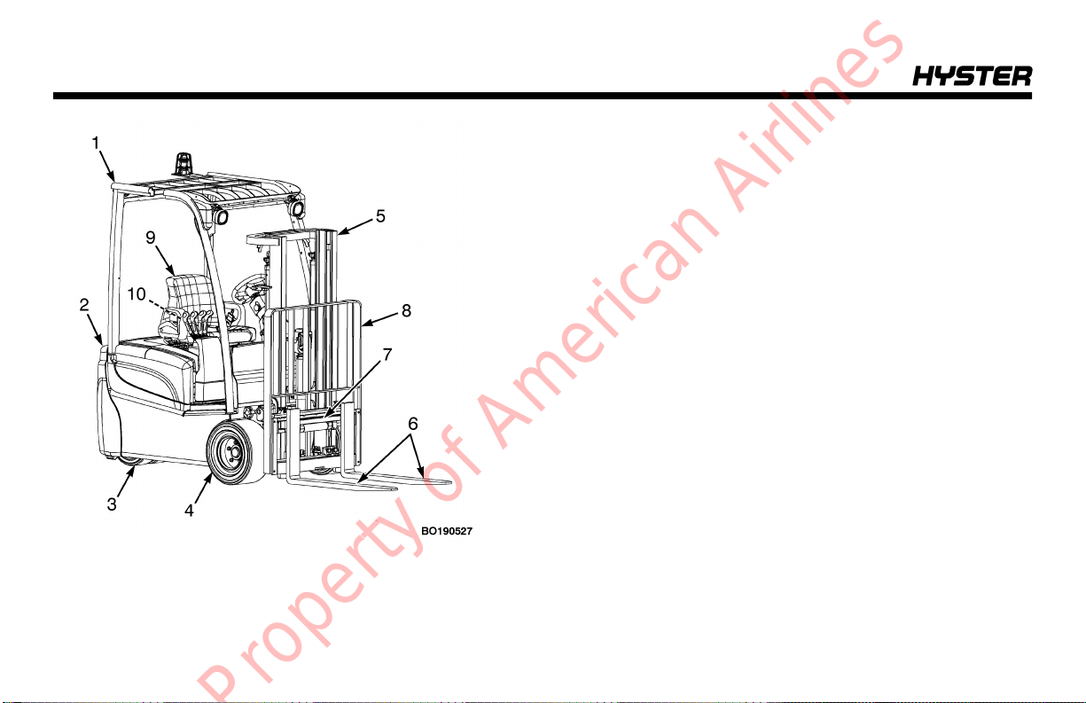
Model Description
Model Description
1. OVERHEAD GUARD
2. COUNTERWEIGHT
3. STEER WHEELS
4. DRIVE WHEELS
5. MAST
6. FORKS
7. CARRIAGE
8. LOAD BACKREST EXTENSION
9. OPERATOR SEAT
10. SEAT BELT AND HIP RESTRAINT
Figure 1. Major Components of the Lift Truck
10

Model Description
Model Description
General
This series of electric lift trucks is available in the following
models: (see Figure 1).
J30XNT, J35XNT, and J40XNT (K160)
The lift trucks covered in this Operating Manual are equipped with solid rubber tires that look like pneumatic tires.
See Wheels and Tires in the Maintenance Section for a
description of these tires.
The operation of the lift truck is the same for all models. A
battery supplies power for the traction motors, hydraulic
pump motor, control panel, and display panel.
The lift trucks covered in this Operating Manual are manufactured with three motors: two traction motors and a
hydraulic pump motor. See Figure 2 and Figure 3.
The motors use AC motor and control technology. The traction motors are mounted between the left and right trans-
missions on the drive axle. The hydraulic pump motor is
mounted behind the driver and in front of the counterweight. See Figure 2 and Figure 3.
In addition to dual, hydraulically-operated, wet disc service
brakes and electrically-operated disc parking brake, the lift
trucks covered in this Operating Manual are equipped with
electric braking (plugging) and an auto brake feature. When
the lift truck is traveling in one direction and the direction
control switch or MONOTROL® pedal is changed to the
opposite direction, the plugging function is energized.
Auto regenerative braking allows the user to set the distance the truck will coast when the direction control switch
is returned to the NEUTRAL position or when the MONOTROL® or accelerator pedal is released.
11
Model Description
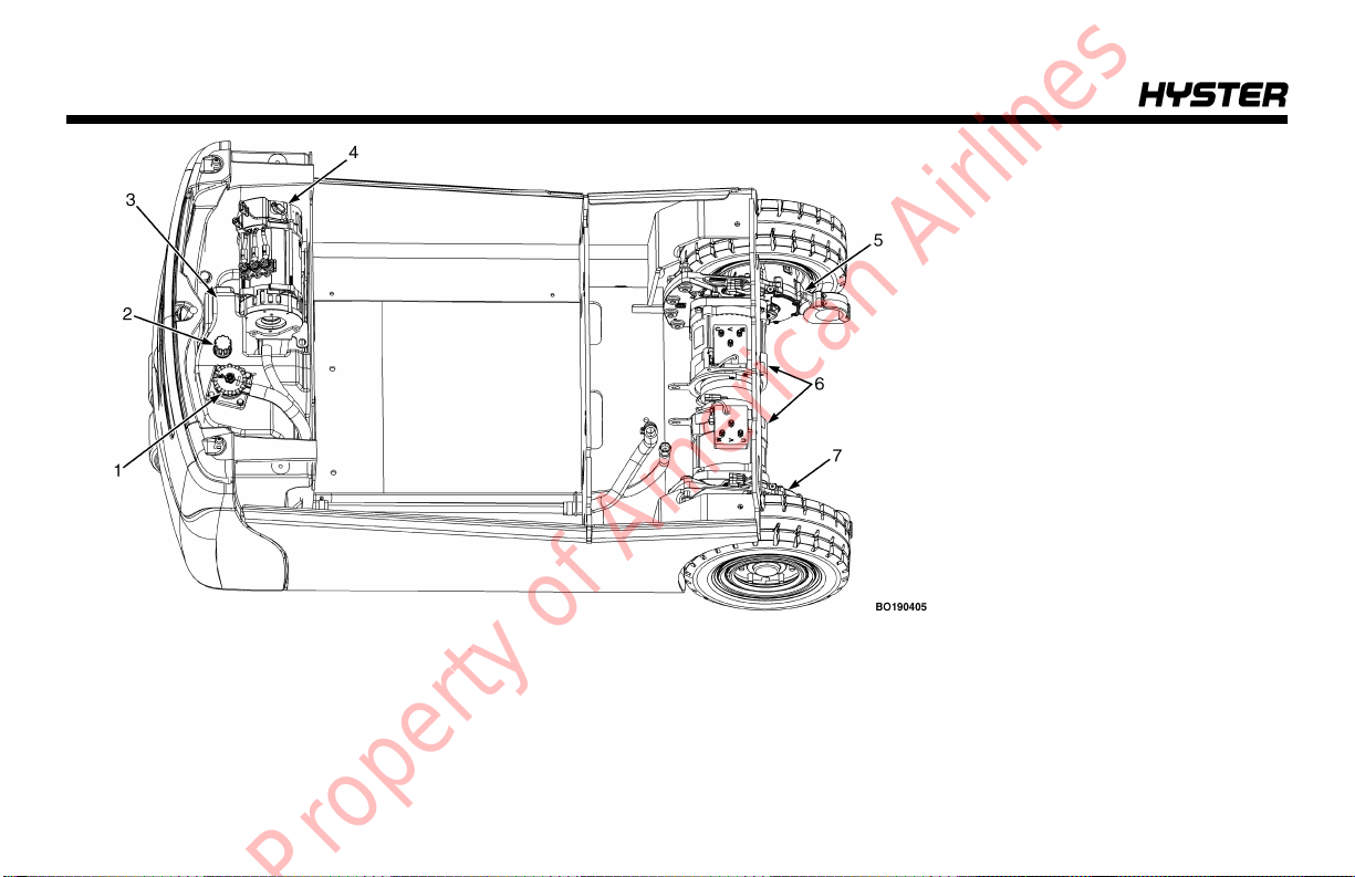
Figure 2. Motor Locations, Lift Trucks Manufactured Before November, 2014
1. HYDRAULIC FILTER
2. HYDRAULIC BREATHER CAP/
DIPSTICK
3. HYDRAULIC TANK
4. HYDRAULIC PUMP MOTOR
5. LEFT TRANSMISSION
6. TRACTION MOTORS
7. RIGHT TRANSMISSION
12
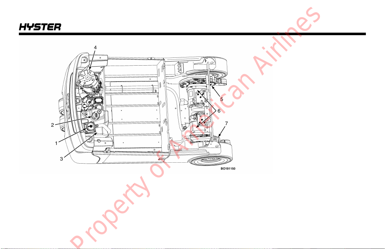
1. HYDRAULIC FILTER
2. HYDRAULIC BREATHER CAP/
DIPSTICK
3. HYDRAULIC TANK
4. HYDRAULIC PUMP MOTOR
5. LEFT TRANSMISSION
6. TRACTION MOTORS
7. RIGHT TRANSMISSION
Figure 3. Motor Locations, Lift Trucks Manufactured After November, 2014
Model Description
13

Model Description
A brake pedal actuates the hydraulic service brakes at the
drive wheels.
The lift trucks covered in this Operating Manual can be
equipped with either standard manual hydraulic levers, or
Electro-Hydraulic (E-Hydraulic) mini-levers.
Forward or reverse movements can be controlled by either
a MONOTROL® pedal or a direction control switch. If the
lift truck is equipped with E-Hydraulic mini-levers, the direction control switch is located on the left side of the armrest,
in front of the horn button. If the lift truck is equipped with
manual hydraulic levers, the direction control switch is located on the left side of the first lever. See Figure 4.
All lift trucks are equipped with a Battery Discharge Indicator (BDI) and an hourmeter. The bar graph type of BDI
shows the state of charge of the battery. These lift trucks
have Liquid Crystal Display (LCD) screen. The LCD screen
shows the battery bar graph and provides other service
information. Hourmeter operating time(s) are also shown
on the LCD screen.
See Display Panel Features in this section for a more
detailed description of how these display panels operate.
14
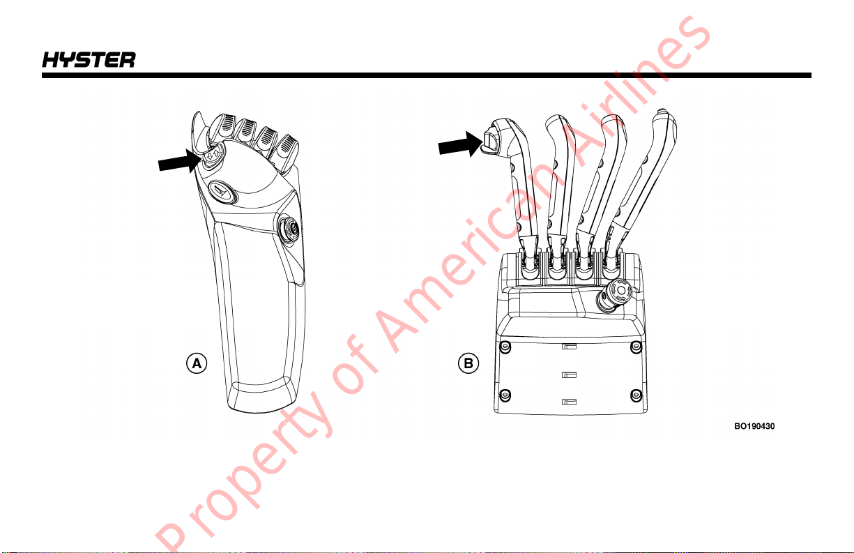
A. E-HYDRAULIC CONTROL MINI-LEVERS B. MANUAL HYDRAULIC CONTROL LEVERS
Model Description
Figure 4. Direction Control Switch
15

Model Description
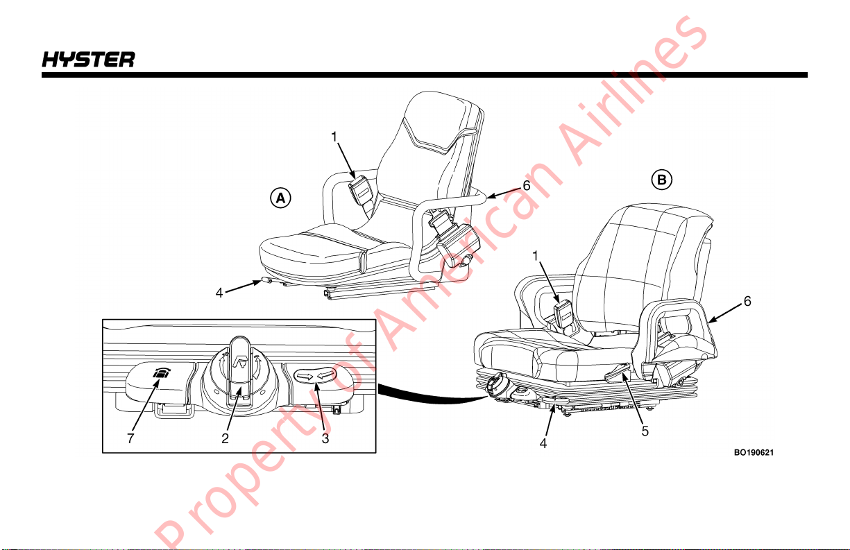
The electric lift trucks described in this manual are equipped with a standard, non-swivel seat or a full suspension
swivel seat. See Figure 5.
The full suspension swivel seat allows the operator to move
the seat to the left and to the right. The seat can be moved
5 degrees to the left and 12 degrees to the right.
The full suspension swivel seat option allows the operator
to better see where he is going when driving the lift truck in
reverse.
16
Model Description
Figure 5. Seat Components
17

Model Description
Legend for Figure 5
A. STANDARD, NON-SWIVEL SEAT B. FULL SUSPENSION SWIVEL SEAT
1. SEAT BELT
2. WEIGHT ADJUSTMENT KNOB
3. RIDE POSITION INDICATOR
4. FORWARD/BACKWARD ADJUSTMENT LEVER
5. BACKREST ANGLE ADJUSTMENT LEVER
6. HIP RESTRAINT BRACKET
7. SWIVEL LATCH RELEASE LEVER
Operator Protection Equipment
The OVERHEAD GUARD is intended to offer reasonable
protection to the operator from falling objects, but cannot
protect against every possible impact. Therefore, it must
not be considered a substitute for good judgment and care
when handling loads. Do not remove the overhead guard.
See Figure 1.
The BATTERY RESTRAINT SYSTEM is designed to hold
the battery within the battery compartment if a tipover
occurs. The battery restraint system contains a front spacer
plate, a battery plate, front and rear bulkheads, and the left
and right frame plates. The lift truck can be equipped with
optional side rollers or fork pockets on the battery plate to
help in removing the battery from the truck.
The hood and hood latch mechanism also help keep the
battery within the battery compartment if a tipover occurs.
18
The hood can be raised for access to the battery. A gas
spring helps raise and hold the hood in the up position.
The battery restraint system must function so that the operator restraint system can operate correctly. Operation of
the battery restraint system requires that the maximum
movement allowed for the battery is 13 mm (0.5 in.) in any
horizontal direction. This will reduce the risk of operator
injury in a truck tipover. An adjustable front battery spacer
plate prevents the front-to-back movement of the battery.
Batteries for this series of lift trucks must all have the same
length dimension to just fit the battery compartment width.
For correct battery sizes, see the Battery Specifications in
the back of this manual.
NOTE: The seat belt can be either black or red.
This lift truck is equipped with one of the three seat belt
configurations.

Model Description
• Seat belt with no operation interlock.
• Seat belt with operation interlock. Seat belt must be fas-
tened for lift truck to start or to travel.
• Seat belt with sequencing interlock. Operator must be in
the seat, then the seat belt fastened before lift truck will
operate. This seat belt is used with the Optional Operator Presence System.
The SEAT BELT and HIP RESTRAINTS provide additional
means to help the operator keep the head and torso substantially within the confines of the truck frame and operator compartment if a tipover occurs. This restraint system is
intended to reduce the risk of the head and torso being
trapped between the lift truck and the ground, but it cannot
protect the operator against all possible injury in a tipover.
The hip restraint will help the operator resist side movement if the seat belt is not fastened. It is not a substitute for
the seat belt. Always fasten the seat belt.
This lift truck may be equipped with an optional operator
presence system which will not allow the truck to travel
unless the seat belt is fastened. When equipped, a seat
belt interlock includes sequencing/logic for the seat pressure switch and seat belt switch. The weight of the operator
must be detected prior to the seat belt switch being
engaged to enable operations.
The LOAD BACKREST EXTENSION is installed to keep
loose parts of the load from falling back toward the operator. It must be high enough, with openings small enough to
prevent the parts of the load from falling backward. If a load
backrest extension that is different from the one installed
on your truck is required, contact your dealer for Hyster lift
trucks.
Nameplate
WARNING
Any change to the lift truck, the tires, or its equipment
can change the lifting capacity. If the Nameplate does
not show the maximum capacity, or if the lift truck
equipment, including the battery for electric trucks,
does not match that shown on the Nameplate, the lift
truck must not be operated.
The capacity is the maximum load that the lift truck can
handle for the load condition shown on the Nameplate. The
capacity is specified in kilograms (kg) and pounds (lb).
19
Model Description
The maximum capacity for the lift truck, at full load height,
must be shown on the Nameplate. Special capacities with
the load height reduced or with optional load centers, may
also be shown on the Nameplate.
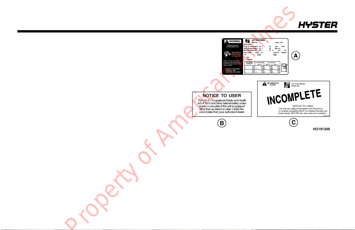
NOTE: The image in Figure 6 is a sample only. Reference
the actual nameplate installed on the truck for actual truck
specifications.
The lift truck serial number code is on the Nameplate. The
serial number code is also stamped on the left side of the
front face of the cowl.
When a lift truck is shipped incomplete from the factory, the
Nameplate is covered by the labels shown in Figure 6. If
your lift truck has this type of label, do not operate the lift
truck. Contact your dealer for Hyster lift trucks to obtain a
complete Nameplate.
A. NAMEPLATE
B. NOTICE LABEL
C. INCOMPLETE LABEL
Figure 6. Nameplate and Label
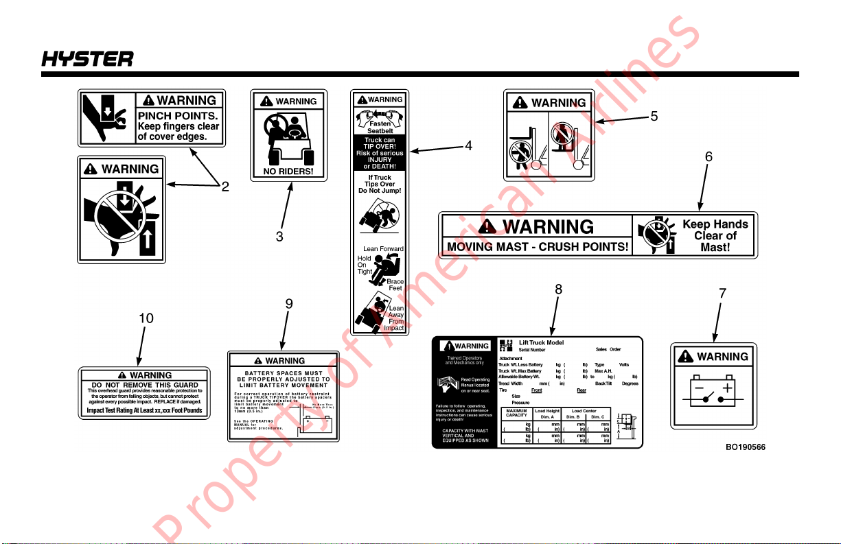
Safety Labels
Safety labels are installed on the lift truck to provide information about possible hazards. It is important that all safety
labels are installed on the lift truck and can be read. See
Figure 7. See the Parts Manual for a list of all the labels
installed on the lift truck and for the location of the labels.
20
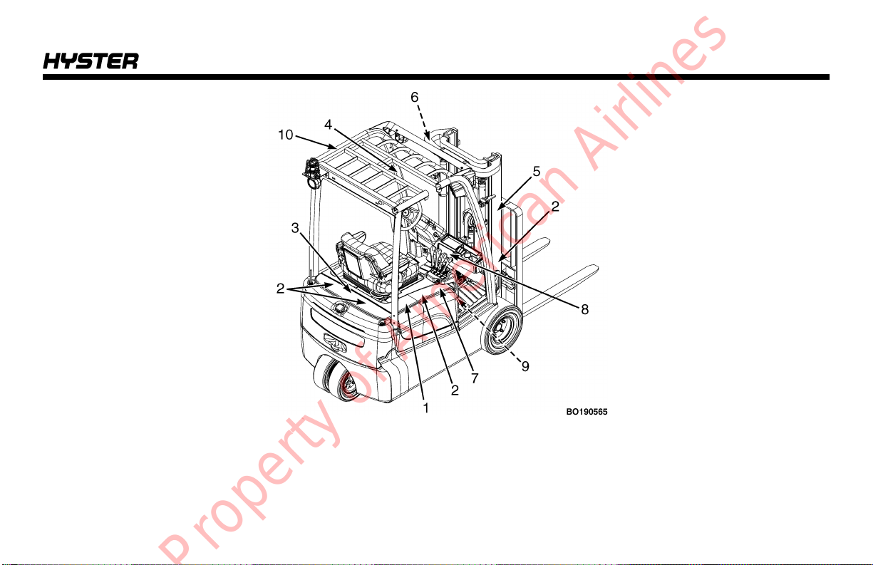
Figure 7. Warning Labels (Sheet 1 of 3)
Model Description
21

Model Description
22
Figure 7. Warning Labels (Sheet 2 of 3)
Model Description
Figure 7. Warning Labels (Sheet 3 of 3)
23

Model Description
1. OPERATOR WARNING
2. PINCH POINTS
3. NO RIDERS
4. TIPOVER WARNING UNITS WITH SEAT BELTS
5. MAST WARNING
Legend for Figure 7
6. MAST WARNING
7. BATTERY DISCONNECT
8. NAMEPLATE
9. BATTERY SPACER
10. OVERHEAD GUARD IMPACT RATING
Operator Controls
(See Figure 8, Figure 9, and Table 1)
WARNING
If any of the levers or pedals do not operate as described in the following tables, report the problem immedi-
24
ately. Injury to personnel can occur if the levers or
pedals do not operate as described in the following
table. DO NOT operate the lift truck until the problem is
corrected.
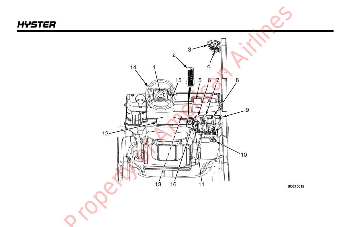
Model Description
Figure 8. Operator Controls - Manual Hydraulic Controls
25
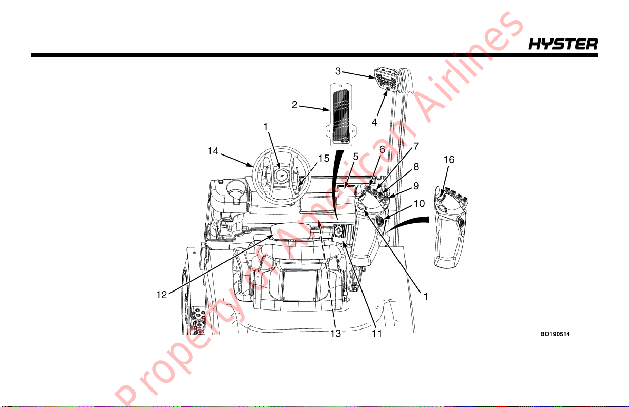
Model Description
26
Figure 9. Operator Controls - Electro-Hydraulic Controls
Model Description
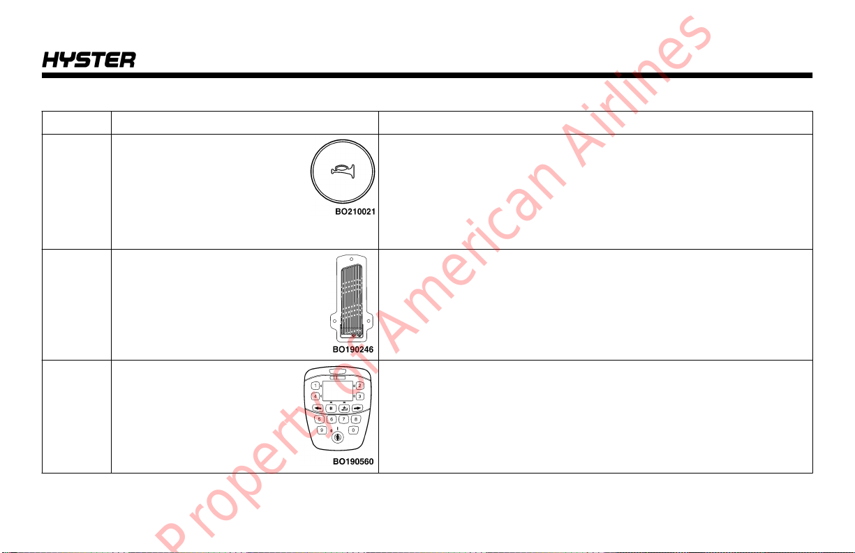
Table 1. Operator Controls (See Figure 8 and Figure 9)
Item No. Item Function
1 Horn Button Push the horn button to warn pedestrians and others when
approaching intersections and other blind areas.
If lift truck is equipped with E-Hydraulic controls, there is another
horn button located on the armrest. There may also be a handle on
the rear right side overhead guard leg that has a horn button on it.
See the end of Table 1 for more information.
2 Accelerator Pedal The accelerator pedal is used with the direction control switch descri-
bed in this table and when the lift truck is not equipped with a MONOTROL® pedal. Push down on the accelerator pedal to increase the
speed of the lift truck
3 Display Panel See Display Panel Features in this section, and Figure 10, Fig-
ure 11, Table 2, and Table 3 for a detailed description.
27

Model Description
Table 1. Operator Controls (See Figure 8 and Figure 9) (Continued)
Item No. Item Function
4 Key Switch and
Keyless Switch
WARNING
The ignition switch is a reed switch which uses an applied magnetic field. If a strong magnet is placed near the ignition switch,
it may not function properly (such as not shutting off power). To
ensure ignition switch functions properly, DO NOT place a magnet near the ignition switch.
The lift trucks covered in this Operating Manual can be equipped
with either a key switch or keyless switch. Both options will have two
positions:
No. 1 Position: OFF position. De-energizes all electric circuits except
for the horn.
No. 2 Position: ON position. Energizes all electric circuits. The key or
keyless switch will be in this position during normal operation.
28
 Loading...