

Hyster Fortis S40FT, Fortis S50FT, Fortis S55FTS, Fortis S70FT, Fortis H40FT Operating Manual
...
OPERATING MANUAL
FORTIS®
S40FT, S50FT, S55FTS, S60FT, S70FT (F187)
H40FT, H50FT, H60FT, H70FT (L177)
Property of American Airlines
DO NOT REMOVE THIS MANUAL FROM THIS UNIT
PART NO. 1580499 10/16

Spacer
LIFT TRUCK MODEL
ENGINE MODEL
TRANSMISSION TYPE
MAST LIFT HEIGHT
CARRIAGE TYPE
DRIVE TIRE SIZE
SERIAL NUMBER
SERIAL NUMBER
SERIAL NUMBER
GROUP NUMBER
GROUP NUMBER
STEERING TIRE SIZE
SPECIAL EQUIPMENT OR ATTACHMENTS
© Hyster Company 2016. All rights reserved.
HYSTER, , FORTENS, and MONOTROL are Registered Trademarks of Hyster-Yale Group, Inc. DURAMATCH, UNISOURCE, and are Trademarks
in the United States and certain other jurisdictions.

Foreword
Foreword
To OWNERS, USERS, and OPERATORS:
The safe and efficient operation of a lift truck requires
skill and alertness on the part of the operator. To develop
the skill required the operator must:
• Receive training in the proper operation of THIS lift truck.
• Understand any potential hazards that may exist in the
work place where the lift truck is intended to be used.
• Understand the capabilities and limitations of the lift
truck.
• Become familiar with the construction of the lift truck and
see that it is maintained in good condition.
• Read and properly understand the warnings, instruc-
tions, and operating procedures in this manual.
In addition, a qualified person, experienced in lift truck
operation, must guide a new operator through several driving and load handling operations before the new operator
attempts to operate the lift truck alone.
©HYSTER COMPANY 2016 1580499 - ENGLISH-US 1
It is the responsibility of the employer to make sure that the
operator can see, hear, and has the physical and mental
ability to operate the equipment safely.
Various laws and regulations require the employer to train
lift truck operators. These laws and regulations include:
• Occupational Safety and Health Act (USA)
• Canada Material Handling Regulations
NOTE: A comprehensive operator training program is avail-
able from Hyster Company. For further details, contact
your dealer for Hyster lift trucks.
This Operating Manual is the original instruction and contains information necessary for the operation and maintenance of a basic lift truck. Optional equipment is sometimes
installed that can change some operating characteristics
described in this manual. Make sure the necessary instructions are available and understood before operating the lift
truck.
Foreword
Some of the components and systems described in this
Operating Manual will NOT be installed on your unit. If you
have a question about any item described, contact your
dealer for Hyster lift trucks.
Additional information that describes safe operation and
use of lift trucks is available from the following sources:
• Employment safety and health standards or regulations
(Examples: "Occupational Safety and Health Standards
(USA)", "Canada Material Handling Regulations".
• Safety codes and standards (Example: Industrial Truck
Standards Development Foundation, ANSI/ITSDF
B56.1, Safety Standard for Low Lift and High Lift
Trucks).
• Publications from government safety agencies, govern-
ment insurers, private insurers and private organizations
(Example: Accident Prevention Manual for Industrial
Operations, from the National Safety Council).
• Guide for Users of Industrial Lift Trucks (Hyster Part No.
852930) describes lift truck safety, good maintenance
practices, and training programs and is available from
your dealer for Hyster lift trucks.
• Lift Truck/Pedestrian Accidents, Causes and Prevention.
Hyster Company (LIFTPED/B 12/2003).
NOTE: Hyster lift trucks are not intended for use on public
roads.
NOTE: The following symbols and words indicate safety
information in this manual:
WARNING
Indicates a hazardous situation which, if not avoided,
could result in death or serious injury.
CAUTION
Indicates a hazardous situation which, if not avoided,
could result in minor or moderate injury and property
damage.
On the lift truck, the WARNING symbol and word are on
orange background. The CAUTION symbol and word
are on yellow background.
2

Contents
Foreword ...................................................................... 1
TO OWNERS, USERS, AND OPERATORS: ............. 1
Warning ........................................................................ 7
Model Description ....................................................... 10
GENERAL ................................................................... 11
OPERATOR PROTECTION EQUIPMENT ................. 14
NAMEPLATE .............................................................. 15
SAFETY LABELS ....................................................... 16
DISPLAY SWITCH CLUSTER .................................... 21
Display Switch Cluster – Right-Side Display Inputs .. 21
Display Switch Cluster – LCD Screen and Warning
and Indicator Lights .............................................. 28
OPERATOR CONTROLS ........................................... 37
OPERATOR CONTROLS – JOYSTICK FEATURES . 57
Operating Procedures ................................................ 63
GENERAL ................................................................... 63
Know Your Lift Truck ................................................ 63
Stability and Center of Gravity .................................. 65
Capacity (Weight and Load Center) ......................... 66
Impact Sensor ........................................................... 67
INSPECTION BEFORE OPERATION ........................ 68
Checks With the Engine Stopped ............................. 68
Mounting and Dismounting ....................................... 69
Contents
Operator Passwords ................................................. 69
Starting Procedures .................................................. 71
Starting Procedures, Trucks With Key Switch .......... 71
Starting Procedures, Trucks With Keyless Start
Option ................................................................... 73
Checks With the Engine Running ............................. 74
Load Weighing Sensor ............................................. 75
Set Load Weight to Zero ........................................... 76
Engine Shutdown ...................................................... 76
OPERATING TECHNIQUES ...................................... 77
Basic Operating Procedures ..................................... 78
Driving and Direction Changes ................................. 83
General ................................................................... 85
Normal Operations .................................................. 85
Standard Operator Presence System ..................... 86
Optional Operator Presence System ...................... 87
Basic Powershift and Powershift 1 Speed
Transmissions .................................................. 87
DuraMatch .............................................................. 88
Inching ...................................................................... 90
Steering (Turning) ..................................................... 91
Load Handling, General ............................................ 92
Load Handling, Lifting, Lowering, and Tilting ............ 93
3

Contents
Load Handling, How to Engage and Disengage a
Load ...................................................................... 96
Load Handling, Traveling .......................................... 99
Load Handling, Emergency Load Lowering .............. 103
HIGHWAY TRUCKS, RAIL CARS, AND DOCKS ....... 105
ATTACHMENTS ......................................................... 106
Disconnecting Attachment Hydraulic Quick-
Disconnect Hoses ................................................. 107
Connecting Attachment Hydraulic Quick-Disconnect
Hoses .................................................................... 108
STOPPING ................................................................. 108
PARKING .................................................................... 109
Maintenance ................................................................ 110
GENERAL ................................................................... 110
Serial Number Data .................................................. 111
HOW TO MOVE A DISABLED LIFT TRUCK .............. 111
How to Tow the Lift Truck ......................................... 111
HOW TO PUT A LIFT TRUCK ON BLOCKS .............. 112
How to Raise the Drive Tires .................................... 112
How to Raise the Steering Tires ............................... 113
HOW TO CLEAN A LIFT TRUCK ............................... 113
Maintenance Schedule ............................................... 114
Maintenance Procedures Every 8 Hours or Daily .... 150
HOW TO MAKE CHECKS WITH THE ENGINE
STOPPED ................................................................. 150
Tires and Wheels ...................................................... 150
Safety Labels ............................................................ 152
Mast, Carriage, Header Hoses, Lift Chains, and
Attachment ............................................................ 152
Operator Restraint System ....................................... 154
Automatic Locking Retractor (ALR) ........................ 157
Emergency Locking Retractor (ELR) ...................... 158
Hood and Seat Latches ............................................ 158
Engine Compartment ................................................ 160
Paper Application ...................................................... 160
Fuel, Oil, and Coolant Leaks, Check ........................ 162
Hydraulic Hoses ........................................................ 162
Coolant Hoses .......................................................... 162
Steering Column Gas Cylinder ................................. 163
Transmission ............................................................ 163
Hydraulic System Oil ................................................ 164
Engine Oil ................................................................. 164
Air Filter .................................................................... 169
Forks ......................................................................... 169
Forks, Remove ......................................................... 169
Forks, Inspect ........................................................... 172
Forks, Install ............................................................. 172
Forks, Adjust ............................................................. 173
HOW TO MAKE CHECKS WITH THE ENGINE
RUNNING ................................................................. 175
4

Contents
Indicator Lights, Horn, Fuses, and Relays ................ 175
Service Brakes .......................................................... 177
Brake Fluid Level .................................................... 177
Operation, Check .................................................... 177
Parking Brake ........................................................... 178
Engine Oil Pressure .................................................. 179
Cooling System ......................................................... 179
Steering System ....................................................... 181
Control Levers and Pedals ....................................... 181
Lift System Operation ............................................... 181
HOW TO ADD FUEL TO THE LIFT TRUCK .............. 182
Liquefied Petroleum Gas (LPG) ................................ 183
LPG Tank, Remove ................................................ 184
LPG Tank, Fill ......................................................... 186
LPG Tank, Install .................................................... 187
Gasoline or Diesel Fuel ............................................ 188
WHEELS AND TIRES ................................................. 188
General ..................................................................... 188
How to Change a Solid Rubber Tire (S Series) ........ 188
Remove and Install the Tire on the Wheel ................ 189
PNEUMATIC TIRE WITH TUBE, REPAIR ................. 191
Remove Wheels From Lift Truck .............................. 191
Remove Tire From Wheel ......................................... 191
Tire Removal, Two-Piece Wheel ............................ 193
Tire Removal, Three- and Four-Piece Wheels ....... 194
Install Wheel in Tire .................................................. 195
Tire Installation, Three- or Four-Piece Wheel ......... 196
Tire Installation, Two-Piece Wheel ......................... 197
Add Air to Pneumatic Tires With Tube ...................... 198
Install the Wheels ..................................................... 199
PNEUMATIC TUBELESS TIRE, REPAIR .................. 199
Remove Tire From Lift Truck .................................... 199
Remove Tire From Wheel ......................................... 200
Install Tire on Wheel ................................................. 202
Add Air to Pneumatic Tubeless Tire ......................... 205
Install the Wheels ..................................................... 206
SOLID RUBBER TIRES ON PNEUMATIC WHEELS,
CHANGE .................................................................. 206
Remove Tire From Wheel ......................................... 206
Install Tire on Wheel ................................................. 208
DUAL DRIVE WHEELS, INSTALL ............................. 210
JUMP-STARTING THE LIFT TRUCK ......................... 211
Jump-Starting Using a Battery Charger .................... 211
Jump-Starting Using Another Lift Truck .................... 211
JUMP-STARTING THE LIFT TRUCK ......................... 212
Jump-Starting Using a Battery Charger .................... 212
Jump-Starting Using Another Lift Truck .................... 212
OPERATING PROCEDURES FOR A NEW OR
REBUILT ENGINE .................................................... 213
CHANGES TO THE OVERHEAD GUARD ................. 213
5

Contents
HOW TO PUT INTERNAL COMBUSTION ENGINE
(ICE) TRUCKS IN STORAGE .................................. 213
Short-Term Storage .................................................. 214
Long-Term Storage ................................................... 215
While the Lift Truck is in Storage .............................. 215
How to Put Batteries in Storage ................................ 215
Putting a Stored Lift Truck Back Into Service ........... 216
HOW TO MOVE A LIFT TRUCK ON A
TRANSPORT ............................................................ 217
Loading ..................................................................... 218
Unloading .................................................................. 219
PREPARATION FOR USE ......................................... 219
Preparation After Transport ...................................... 219
6
WARNING
FAILURE TO FOLLOW THESE INSTRUCTIONS CAN CAUSE SERIOUS INJURY OR DEATH!
AUTHORIZED, TRAINED OPERATOR ONLY!
KNOW THE EQUIPMENT:
• ALWAYS use 3 points of contact when getting on and off
the truck.
Warning
• VERIFY truck is equipped with overhead guard and load
backrest adequate for the load.
LOOK WHERE YOU ARE GOING:
• KNOW operating, inspection, and maintenance instruc-
tions in Operating Manual.
• DO NOT operate or repair truck unless trained and
authorized.
• INSPECT truck before use.
• DO NOT operate if truck needs repair. Tag truck and
remove key. Repair truck before use. Always use Hyster
Approved parts when making repairs. Replacement
parts must meet or exceed the specifications of the original equipment manufacturer.
• USE auxiliary equipment (attachments) for intended purpose only.
• IF YOU CAN'T SEE, DON'T GO.
• TRAVEL in reverse if load blocks forward vision.
• MAKE SURE tail swing area is clear.
• SOUND horn at intersections or where vision is blocked.
• WATCH clearances, especially overhead.
KNOW YOUR LOADS:
• HANDLE only stable loads within specified weight and
load center. See Nameplate on truck.
• DO NOT handle loose loads higher than load backrest.
• SPACE forks as far apart as load allows and center load
between forks. Keep load against load backrest.
7

Warning
WARNING
FAILURE TO FOLLOW THESE INSTRUCTIONS CAN CAUSE SERIOUS INJURY OR DEATH!
AUTHORIZED, TRAINED OPERATOR ONLY!
USE COMMON SENSE:
• DO NOT use truck to lift people unless there is no other
practical option. Then, use only a securely attached special work platform. Follow instructions in this Operating
Manual.
• OBEY traffic rules. Yield right-of-way to pedestrians.
• BE in complete control at all times.
• ALLOW NO ONE under or near lift mechanism or load.
• OPERATE truck only from operator's seat.
• KEEP arms, legs, and head inside operator's compart-
ment.
• DO NOT move truck if anyone is between truck and stationary object.
• WHEN PARKING, also shut off power, close LPG fuel
valve, block wheels on inclines.
KNOW THE AREA:
• NEVER enter a trailer or railroad car unless its wheels
are blocked.
• CONFIRM floor strength.
• FILL fuel tank or charge battery only in designated area.
• TURN OFF engine when fueling.
• AVOID sparks or open flame. Provide ventilation.
• DO NOT start if fuel is leaking.
• KEEP vent caps clear when charging battery.
• DISCONNECT battery during servicing.
• BEFORE DISMOUNTING, neutralize travel control,
lower carriage, and set brake.
8
• CHECK dockboard width, capacity, and security.

WARNING
FAILURE TO FOLLOW THESE INSTRUCTIONS CAN CAUSE SERIOUS INJURY OR DEATH!
AUTHORIZED, TRAINED OPERATOR ONLY!
PROTECT YOURSELF FASTEN YOUR SEAT BELT!
• AVOID bumps, holes, and loose materials.
• AVOID sudden starts or stops.
• NEVER turn on or angle across an incline.
• TRAVEL on inclines with load uphill or when unloaded
with lift mechanism downhill.
• TILT mast slowly and smoothly. LIFT or LOWER with
upright vertical or tilted slightly back. Use minimum tilt
when stacking elevated loads.
Warning
• TRAVEL with carriage as low as possible and tilted
back.
• SLOW DOWN before turning, especially without load.
FAILURE TO FOLLOW THESE INSTRUCTIONS CAN
CAUSE THE LIFT TRUCK TO TIP.
DO NOT JUMP off if the truck tips over. HOLD steering
wheel firmly. BRACE your feet. LEAN FORWARD and
AWAY from point of impact.
9
Model Description
Model Description
Figure 1. Model View Showing Major Components of S40-70FT, S55FTS Series
COMPONENTS FOR H40-70FT TRUCKS ARE IN SAME
LOCATIONS.
1. OVERHEAD GUARD
2. TAIL, BRAKE, AND REVERSE LIGHTS
3. SEAT
4. COUNTERWEIGHT
5. STEERING AXLE
6. SEAT BELT AND HIP RESTRAINT
7. DRIVE AXLE
8. CARRIAGE
9. FORKS
10. LOAD BACKREST EXTENSION
11. PARKING BRAKE
12. STEERING WHEEL
13. MAST
14. OPERATING MANUAL (BEHIND SEAT)
10

Model Description
Model Description
General
This Operating Manual is for the following models of lift
trucks:
S40FT, S50FT, S55FTS, S60FT, and S70FT (F187)
H40FT, H50FT, H60FT, and H70FT (L177)
These lift trucks are available with the following engines:
• Mazda 2.0L engine which uses gasoline or LPG fuel
• Mazda 2.2L engine which uses gasoline or LPG fuel
• GM 2.4L engine which uses gasoline or LPG fuel
• Yanmar 2.6L engine which uses diesel fuel
• Yanmar 3.3L engine which uses diesel fuel
Prior to January, 2011, these lift truck models can be
equipped with a Basic Powershift (iron case), Powershift 1
Speed (aluminum case gear drive) or DuraMatch transmission (see Table 1). After January 2011, these truck models
will be equipped with a Powershift 1 Speed (aluminum case
chain drive) or DuraMatch transmission (see Table 1) and
can be equipped with three types of controls:
• A MONOTROL® pedal that controls both the forward
and reverse operation of the powershift transmission and
the speed of the engine.
• A Direction Control Lever on the left side of the Display
Switch Cluster that controls the forward, neutral, and
reverse operation of the powershift transmission. A separate accelerator pedal controls the engine speed.
• A directional control switch integrated into the armrest on
units equipped with E-hydraulics controls both forward
and reverse operation of the transmission. A separate
accelerator pedal controls engine speed.
The S40-70FT lift trucks are equipped with solid rubber
tires. The H40-70FT lift trucks are equipped with pneumatic
tires or solid pneumatic-shaped tires. See Wheels and
Tires in the Maintenance Section for a description of
these tires.
If your lift truck is an S40-70FT, S55FTS (F187) with manual hydraulics and manufactured prior to March, 2009, it is
not equipped an emergency lowering valve. If manufactured after March, 2009, it is equipped with an emergency
lowering valve.
11

Model Description
If your lift truck is an H40-70FT (L177) with manual hydraulics and manufactured prior to March, 2009, is it not equipped with an emergency lowering valve. If manufactured
after March, 2009, it is equipped with an emergency lowering valve.
If your lift truck is equipped with electronic hydraulics, it has
an emergency lowering valve.
This emergency lowering valve (see Figure 15) allows the
operator or service technician to lower the lift truck's mast
assembly if the electrical signal to the main control valve is
disrupted. See the section Load Handling, Emergency
Load Lowering in the Operating Procedures section.
12

Table 1. Transmissions
Model Description
Operational
Feature
Electronic Inching Yes Yes
Electronic Control of
Direction Changes
Auto Deceleration – Yes
Controlled Power Reversal – Yes
Roll Reduction Feature – Yes
Roll Back Feature – Yes
Reduced Drive Tire Slippage – Yes
Powershift 1 Speed Transmission
Basic Powershift or
Yes Yes
DuraMatch Transmission
13
Model Description
1. BASIC POWERSHIFT TRANSMISSION
2. DURAMATCH TRANSMISSION
3. POWERSHIFT 1 SPEED TRANSMISSION
Figure 2. Transmission Labels
Operator Protection Equipment
The LOAD BACKREST EXTENSION is installed to keep
loose parts of the load from falling back toward the operator. It must be high enough, with vertical openings small
enough, to prevent the parts of the load from falling backwards. If a load backrest extension that is different from the
one installed on your lift truck is required, contact your Hys-
ter lift truck dealer.
The OVERHEAD GUARD is intended to offer reasonable
protection to the operator from falling objects, but cannot
protect against every possible impact. Therefore, it must
not be considered a substitute for good judgment and care
when handling loads. Do not remove the overhead guard.
NOTE: The seat belt can be either black or red.
The SEAT BELT AND HIP RESTRAINT provide additional
means to help the operator keep the head and torso substantially within the confines of the lift truck frame and overhead guard if a tipover occurs. This restraint system is
intended to reduce the risk of the head and torso being
trapped between the lift truck and the ground, but it cannot
protect the operator against all possible injury in a tipover.
The hip restraint will help the operator resist side movement. It is not a substitute for the seat belt. Always fasten
the seat belt.
This lift truck may be equipped with an optional operator
presence system which will not allow the truck to travel
unless the seat belt is fastened. When equipped, the seat
belt interlock includes sequencing/logic for the seat pressure switch and seat belt switch. The weight of the operator
must be detected prior to the seat belt switch being
engaged to enable operations.
14

Model Description
Nameplate
WARNING
DO NOT add to or modify the lift truck. Any modification that affects the safe operation of the truck cannot
be undertaken without the written authorization of Hyster Company.
Any change to the lift truck, the tires, or its equipment
can change the lifting capacity. The lift truck must be
rated as equipped and the Nameplate must show the
new capacity rating.
The capacity is specified in kilograms (kg) and pounds (lb).
The capacity is the maximum load that the lift truck can
handle for the load condition shown on the Nameplate.
The maximum capacity for the lift truck, at full load height,
must be shown on the Nameplate. Special capacities with
the load height reduced or with optional load centers, may
also be shown on the Nameplate.
The lift truck serial number code is on the Nameplate. The
serial number code is also stamped on the right-hand side
of the lift truck frame, under the floorplate.
When a lift truck is shipped incomplete from the factory, the
Nameplate is covered by an INCOMPLETE label as shown
in Figure 3. If the equipment on the truck is changed, the
Nameplate is covered by a NOTICE label as shown in Fig-
ure 3. If your lift truck has either of these labels, do not
operate the lift truck. Contact your dealer for lift trucks to
obtain a complete and correct Nameplate.
15
Model Description
Safety Labels
Safety labels are installed on the lift truck to provide information about possible hazards. It is important that all safety
labels are installed on the lift truck and can be read. See
Figure 4.
All possible label configurations that can be on the lift
trucks covered in this Operating Manual are not shown in
Figure 4. See the Parts Manual for label part numbers and
a complete listing of all labels that are available for the lift
trucks covered in this Operating Manual.
A. NAMEPLATE
B. NOTICE LABEL
Figure 3. Nameplate and Labels
16
C. INCOMPLETE LABEL
Model Description
LABELS FOR H40-70FT TRUCKS ARE IN SAME LOCATIONS.
Figure 4. Warning and Safety Labels (Sheet 1 of 3)
17

Model Description
SEE THE PARTS MANUAL FOR THE PART NUMBER.
18
Figure 4. Warning and Safety Labels (Sheet 2 of 3)
Model Description
SEE THE PARTS MANUAL FOR THE PART NUMBER.
Figure 4. Warning and Safety Labels (Sheet 3 of 3)
19

Model Description
Legend for Figure 4
1. FLAMMABLE LP-GAS
2. TIPOVER WARNING
3. OVERHEAD GUARD LABEL
4. WARNING, OPERATION
5. NO RIDERS
6. WARNING FOR PARKING BRAKE
7. MAST WARNING
8. NAMEPLATE
9. DRIVE TRAIN PROTECTION CAUTION
10. NO ONE ON OR UNDER FORKS
*THIS PARKING BRAKE LABEL (SEE SHEET 2) USED ON LIFT TRUCKS MANUFACTURED AFTER JANUARY, 2012.
**THIS LABEL USED ON LIFT TRUCKS MANUFACTURED AFTER JANUARY, 2012.
11. MAST WARNING
12. OPTIONAL FIRE SAFETY RATING
13. FAN WARNING
14. JOYSTICK LABEL
15. DIESEL FUEL LABEL (NOT SHOWN)
16. UNLEADED FUEL LABEL (NOT
SHOWN)
17. TRANSMISSION LABEL (EXAMPLE
ONLY)
18. LIFT AND TILT LABEL
19. ANTIFREEZE WARNING
20. BORON-FREE LABEL
21. LPG TANK WARNING
22. BRAKE FLUID WARNING (PNEUMATIC
TRUCKS ONLY)
23. LOCKING GAS SPRING
24. HOOD OPENING CAUTION
25. EITHER WARNING (DIESEL ONLY)
26. RADIAL TIRES AND WHEELS
(PNEUMATIC TIRES ONLY)
27. SOOT TRAP WARNING (DIESEL ONLY)
28. SPLIT WHEEL WARNING (PNEUMATIC
TIRES ONLY)
29. UL LABEL
30. STABILITY SYSTEM LABEL (ON BOTH
SIDES OF TRUCK)**
20

Model Description
Display Switch Cluster
WARNING
If any of the instruments, levers, or pedals do not operate as described in the following tables, report the
problem immediately. DO NOT operate the lift truck
until the problem is corrected.
NOTE: On the lift truck models covered in this manual, the
left side (see Figure 5) of the Display Switch Cluster does
not perform any functions.
Display Switch Cluster – Right-Side Display Inputs
The lift trucks covered in this manual can have several different options and configurations. Depending on the equipment on the lift truck, warning and indicator lights on the
right side of the Display Switch Cluster will vary and the
truck may not contain all the warning and indicator lights
shown in Figure 6 and Table 2.
21
Model Description
1. LEFT SIDE DISPLAY INPUTS
2. LCD SCREEN
3. RIGHT SIDE DISPLAY INPUTS
4. WARNING AND INDICATOR LIGHTS
22
Figure 5. Display Switch Cluster
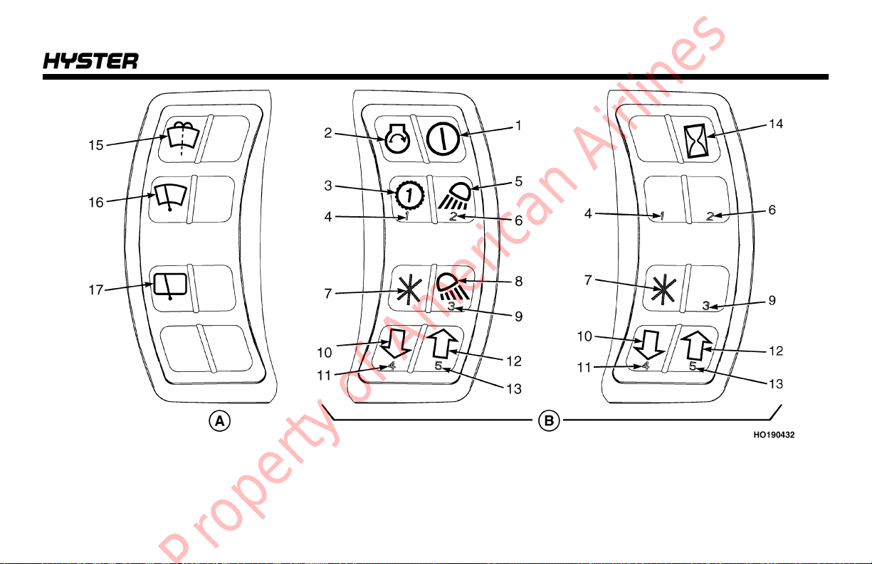
A. LEFT SIDE DISPLAY – CAB OPTION H40-70FT ONLY B. RIGHT SIDE DISPLAY
Model Description
Figure 6. Display Switch Cluster
23
Model Description
Table 2. Display Switch Cluster – Right-Side Display Inputs (See Figure 6)
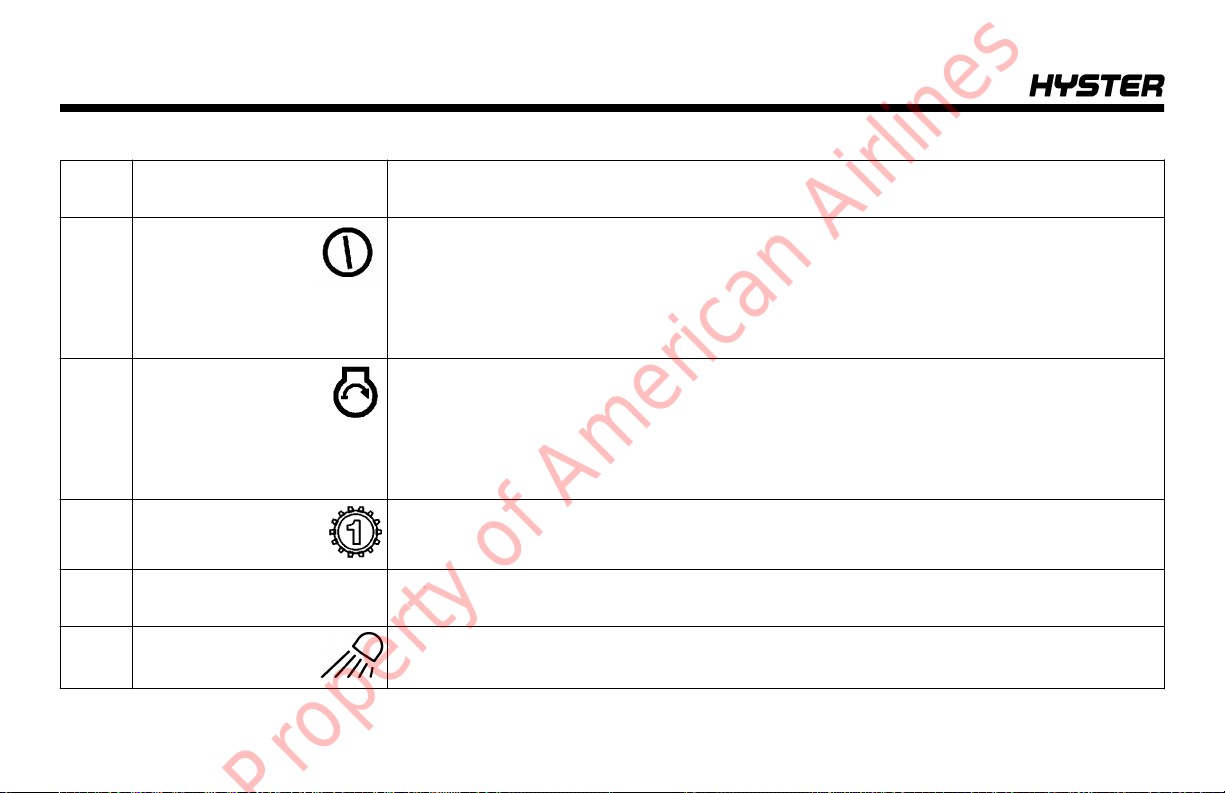
Item
No.
1 Power ON/OFF If the lift truck is equipped with the keyless start option, lift truck system power is
2 Engine Start This button is used when the lift truck is equipped with the keyless start option. The
1st Gear Locking
Button
4 #1 Button When an operator or supervisor is in the main menu for entering and administering
5 Front Work Lights This button controls the front work lights and the marker lights on lift trucks equipped
24
Item Function
turned ON by pressing this button. To turn the lift truck system power and engine OFF,
press the Power ON/OFF button again.
If lift truck has a key switch, the Power ON/OFF symbol is replaced with the Hourmeter
symbol.
engine is started by pressing and holding this button. Lift truck power must be turned
ON (pressing Power ON/OFF button) before starting engine.
If the lift truck contains a key switch, the Engine Start graphic is covered and the function disabled.
This button engages and disengages the 1st Gear Locking function on trucks equipped with a the DuraMatch plus 2 transmission.
passwords, this button is used to enter the number 1 for password purposes.
with this option.
Model Description
Table 2. Display Switch Cluster – Right-Side Display Inputs (See Figure 6) (Continued)
Item
No.
6 #2 Button If the lift truck is equipped with front work lights, the #2 Button and the Front Work
7 Enter Button This button is used for menu entry, navigation, and data entry.
8 Rear Work Lights This button controls the rear work lights on lift trucks equipped with this option.
9 #3 Button If the lift truck is equipped with rear work lights, the #3 Button and the Rear Work Light
Item Function
Light button will share space on the Display Switch Cluster.
When an operator or supervisor are in the main menu for entering and administering
passwords, the Front Work Lights function is disabled and the button is enabled to
enter the number 2 for password purposes. If the lift truck is not equipped with Front
Work Lights, then this button functions only as Password entry #2.
button will share space on the Display Switch Cluster.
When an operator or supervisor is in the main menu for entering and administering
passwords, the Rear Work Lights function is disabled and the button is enabled to
enter the number 3 for password purposes. If the lift truck is not equipped with rear
work lights, then this button functions only as Password entry #3.
25
Model Description
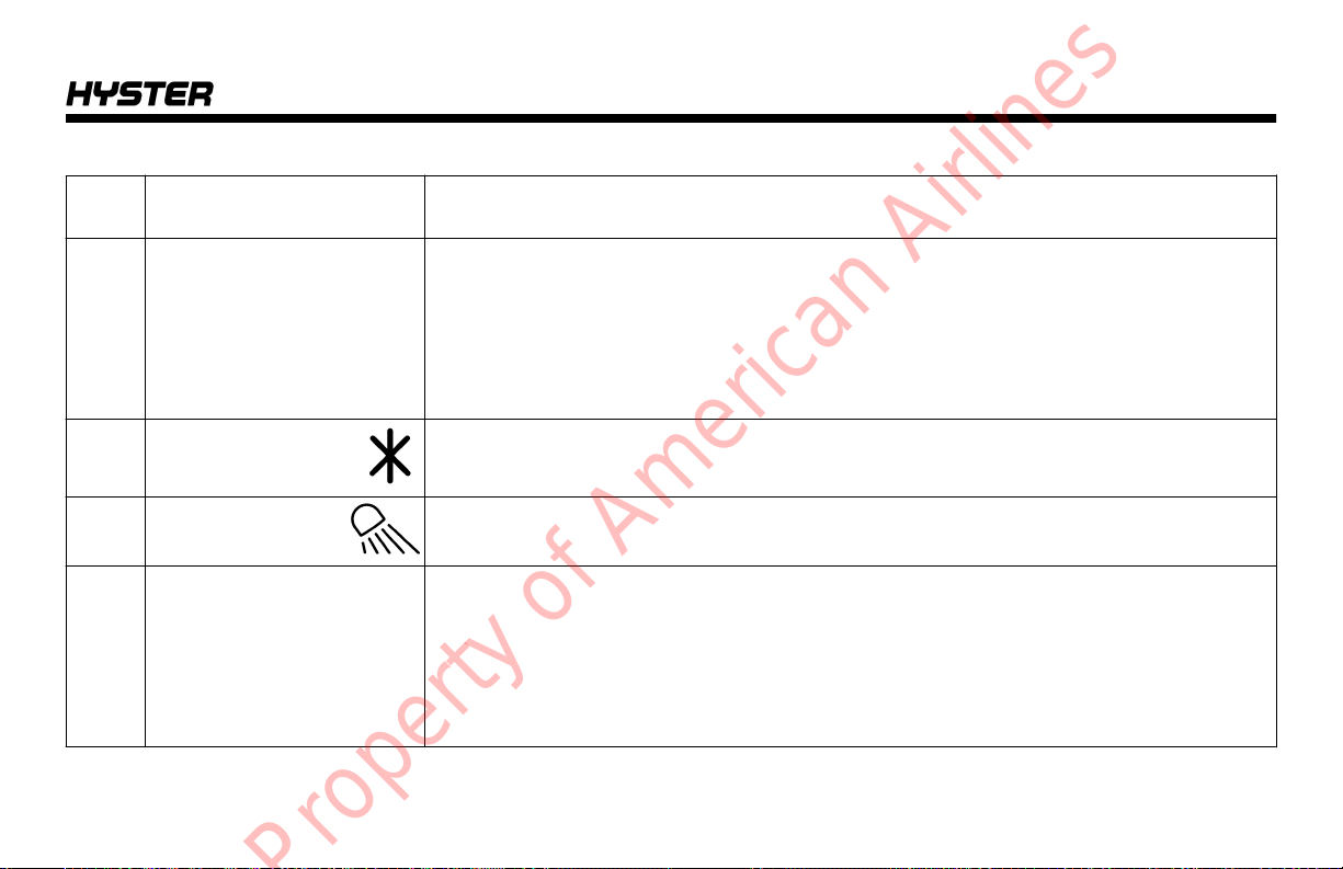
Table 2. Display Switch Cluster – Right-Side Display Inputs (See Figure 6) (Continued)
Item
No.
10 Scroll Down This button is used for the following functions:
11 #4 Button The Scroll Down and #4 Button share the same space on the Display Switch Cluster.
12 Scroll Up This button is used for the following functions:
13 #5 Button The Scroll Up and #5 Button share the same space on the Display Switch Cluster.
26
Item Function
• Decreasing the value of a selected operating function
• Scrolling downward through a list of possible menu selections
When an operator or supervisor is in the main menu for entering and administering
passwords, the Scroll Down function is disabled and the button is enabled to enter the
number 4 for password purposes.
• Increasing the value of a selected operating function
• Scrolling upward through a list of possible menu selections
When an operator or supervisor is in the main menu for entering and administering
passwords, the Scroll Up function is disabled and the button is enabled to enter the
number 5 for password purposes.
Model Description
Table 2. Display Switch Cluster – Right-Side Display Inputs (See Figure 6) (Continued)
Item
No.
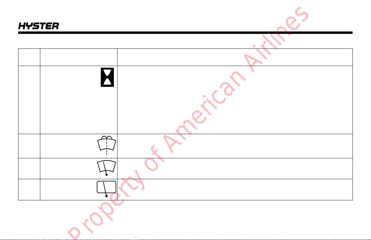
14 Hourmeter On trucks with key switch start, when truck is ON, engine hours will be displayed on
15 Windshield Washer On lift trucks with the cab option, press this button to wash the front windshield. Wind-
16 Front Windshield
Wiper
17 Rear Windshield
Wiper
Item Function
LCD screen on right side of second line. When truck is OFF, press hourmeter button to
display engine hours.
On trucks with keyless start option, when truck is ON, engine hours will be displayed
on LCD screen on right side of second line. When truck is OFF, engine hours can be
displayed when accessing menu to enter password. Password not required to view
engine hours.
Periodic Maintenance recommendations are based on these hours.
shield wipers will turn on and off automatically.
On lift trucks with cab option, press this switch to turn the front windshield wiper ON.
Press the switch again to turn the front windshield wiper OFF.
On lift trucks with cab option, press this switch to turn the rear windshield wiper ON.
Press the switch again to turn the rear windshield wiper OFF.
27

Model Description
Display Switch Cluster – LCD Screen and Warning and Indicator Lights
The LCD screen (see Figure 7) shows operator messages
for the different functions. The LCD screen can display
messages on two lines with up to 20 characters per line.
Bar graphs are also shown on the display using solid block
characters of varying heights.
The following information is displayed on the LCD screen
when the truck is running:
• Engine coolant temperature (standard)
• Fuel level, diesel and gasoline engines (standard)
The engine coolant temperature is displayed on the top line
and the fuel level is shown on the bottom line. If load
weight and travel speed options are available, press the
scroll down button to display the information for these features. Press the scroll up button to return to the engine
coolant temperature and fuel level displays. If a fault
occurs, the fault number will be displayed on the top line.
The time of day is displayed on the right side of the top line
at all times during the selection of displayed text. "HYD
TEMP/FUNCTION REDUCED" is displayed when the
hydraulic oil temperature is higher or lower than specified
limits.
The warning lights and indicator symbols shown in Fig-
ure 7 are on all lift truck models. Depending on the equipment on the lift truck, the warning and indicator lights on
the Display Switch Cluster will vary and not all the warning
and indicator lights shown in Figure 7 will illuminate. When
the warning lights and indicators are on, the operator will
see the appropriate symbol. When the warning lights and
indicators are off, the operator will see a black panel.
Unless noted in Table 3, all programmed warning and indicator lights will light up for two seconds (Start Check) when
System Power is turned ON.
28
 Loading...