

Hyster 4TNE94L-BSNMH Operating Manual
YANMAR DIESEL
ENGINES
2.6L, 3.0L AND 3.3L
H1.6-1.8FT, H2.0FTS (H30-35FT, H40FTS) [F001, G001];
H2.0-3.5FT (H40-70FT) [L177, N177, P177];
H2.0-2.5CT (H50CT) [A274, B274];
H2.0-3.0XT (H40-60XT) [A380];
H2.0UT, H2.5UT, H3.0UT, H3.5UT (H40UT, H50UT,
H60UT, H70UT) [A3C1]
PART NO. 1598588 0600 SRM 1205
SAFETY PRECAUTIONS
MAINTENANCE AND REPAIR
• When lifting parts or assemblies, make sure all slings, chains, or cables are correctly fastened, and
that the load being lifted is balanced. Make sure the crane, cables, and chains have the capacity to
support the weight of the load.
• Do not lift heavy parts by hand, use a lifting mechanism.
• Wear safety glasses.
• DISCONNECT THE BATTERY CONNECTOR before doing any maintenance or repair on electric lift
trucks. Disconnect the battery ground cable on internal combustion lift trucks.
• Always use correct blocks to prevent the unit from rolling or falling. See HOW TO PUT THE LIFT
TRUCK ON BLOCKS in the Operating Manual or the Periodic Maintenance section.
• Keep the unit clean and the working area clean and orderly.
• Use the correct tools for the job.
• Keep the tools clean and in good condition.
•
Always use HYSTER ®APPROVED parts when making repairs. Replacement parts must meet or
exceed the specifications of the original equipment manufacturer.
• Make sure all nuts, bolts, snap rings, and other fastening devices are removed before using force to
remove parts.
• Always fasten a DO NOT OPERATE tag to the controls of the unit when making repairs, or if the unit
needs repairs.
•
Be sure to follow the WARNING and CAUTION notes in the instructions.
• Gasoline, Liquid Petroleum Gas (LPG), Compressed Natural Gas (CNG), and Diesel fuel are
flammable. Be sure to follow the necessary safety precautions when handling these fuels and when
working on these fuel systems.
• Batteries generate flammable gas when they are being charged. Keep fire and sparks away from the
area. Make sure the area is well ventilated.
NOTE: The following symbols and words indicate safety information in this
manual:
WARNING
Indicates a hazardous situation which, if not avoided, could result in death
or serious injury.
CAUTION
Indicates a hazardous situation which, if not avoided, could result in minor
or moderate injury and property damage.
On the lift truck, the WARNING symbol and word are on orange background. The CAUTION symbol and word are on yellow background.
WARNING
California Proposition 65 - Operating, servicing and maintaining a powered industrial truck can
expose you to chemicals including engine exhaust, carbon monoxide, phthalates, and lead, which are
known to the State of California to cause cancer and birth defects or other reproductive harm. For
more information, go to www.P65Warnings.ca.gov.

Table of Contents
TABLE OF CONTENTS
General...................................................................................................................................................................1
Engine Identification.......................................................................................................................................... 1
Major Engine Component Identification.........................................................................................................1
Location of Labels.............................................................................................................................................2
Engine Removal and Installation......................................................................................................................... 3
Cylinder Head Assembly Repair...........................................................................................................................4
Glow Plugs...........................................................................................................................................................5
Remove..............................................................................................................................................................5
Install................................................................................................................................................................ 6
Valve Cover..........................................................................................................................................................6
Remove..............................................................................................................................................................6
Clean and Inspect.............................................................................................................................................6
Install................................................................................................................................................................ 6
Rocker Arm Assembly.........................................................................................................................................7
Remove..............................................................................................................................................................7
Disassemble...................................................................................................................................................... 8
Clean and Inspect.............................................................................................................................................8
Push Rods.......................................................................................................................................................8
Rocker Arm Assembly....................................................................................................................................8
Assemble........................................................................................................................................................... 9
Install................................................................................................................................................................ 9
Valve Clearance Adjustments............................................................................................................................ 9
Cylinder Head Assembly.................................................................................................................................. 11
Remove............................................................................................................................................................11
Disassemble.................................................................................................................................................... 15
Valves and Valve Springs, Remove.............................................................................................................15
Valve Guides, Remove................................................................................................................................. 15
Clean and Inspect...........................................................................................................................................15
Cylinder Head.............................................................................................................................................. 16
Valve Guides................................................................................................................................................ 16
Valves........................................................................................................................................................... 17
Valve Sink.................................................................................................................................................... 17
Valve Seat.....................................................................................................................................................17
Valve Springs............................................................................................................................................... 18
Assemble......................................................................................................................................................... 18
Valve Guides, Install................................................................................................................................... 18
Valves and Valve Springs, Install...............................................................................................................19
Install.............................................................................................................................................................. 20
Timing Gear Case and Timing Gears Repair.....................................................................................................22
Timing Gear Case Cover...................................................................................................................................22
Remove............................................................................................................................................................22
Clean and Inspect...........................................................................................................................................22
Install.............................................................................................................................................................. 23
Timing Gears.....................................................................................................................................................23
Crankshaft Gear.............................................................................................................................................24
Remove......................................................................................................................................................... 24
Install............................................................................................................................................................24
Idler Gear........................................................................................................................................................24
Remove......................................................................................................................................................... 24
Inspect.......................................................................................................................................................... 25
Install............................................................................................................................................................25
Camshaft.........................................................................................................................................................25
©2021 HYSTER COMPANY
i

Table of Contents
TABLE OF CONTENTS (Continued)
Remove......................................................................................................................................................... 25
Install............................................................................................................................................................26
Timing Gear Case............................................................................................................................................. 26
Remove............................................................................................................................................................26
Clean and Inspect...........................................................................................................................................27
Install.............................................................................................................................................................. 27
Drive Train, Camshaft, and Cylinder Block Repair.......................................................................................... 28
Remove...............................................................................................................................................................28
Disassemble.......................................................................................................................................................28
Pistons and Connecting Rods.........................................................................................................................28
Crankshaft...................................................................................................................................................... 30
Camshaft.........................................................................................................................................................32
Clean and Inspect..............................................................................................................................................33
Cylinder Block................................................................................................................................................ 33
Honing and Boring.......................................................................................................................................36
Pistons.............................................................................................................................................................37
Piston Pin........................................................................................................................................................37
Connecting Rod...............................................................................................................................................38
Tappets............................................................................................................................................................38
Crankshaft...................................................................................................................................................... 38
Camshaft.........................................................................................................................................................40
Camshaft Bushing..........................................................................................................................................40
Assemble............................................................................................................................................................40
Camshaft.........................................................................................................................................................40
Crankshaft...................................................................................................................................................... 41
Pistons and Connecting Rods.........................................................................................................................41
Install.................................................................................................................................................................43
Lubrication System Repair................................................................................................................................. 44
Engine Oil and Oil Filter Change.................................................................................................................... 44
Oil Pan............................................................................................................................................................... 44
Remove............................................................................................................................................................44
Install.............................................................................................................................................................. 45
Oil Suction Tube................................................................................................................................................45
Remove............................................................................................................................................................45
Clean............................................................................................................................................................... 46
Install.............................................................................................................................................................. 46
Oil Pump............................................................................................................................................................46
Remove............................................................................................................................................................46
Clean and Inspect...........................................................................................................................................47
Outer Rotor Outside Clearance...................................................................................................................47
Outer Rotor to Inner Rotor Tip Clearance..................................................................................................47
Outer Rotor Side Clearance.........................................................................................................................47
Rotor Shaft Clearance..................................................................................................................................48
Install.............................................................................................................................................................. 48
Fuel System Repair............................................................................................................................................. 50
Fuel Injectors.....................................................................................................................................................50
Remove............................................................................................................................................................50
Inspect.............................................................................................................................................................51
Clean............................................................................................................................................................... 51
Test..................................................................................................................................................................51
Install.............................................................................................................................................................. 54
Electronic Throttle System...............................................................................................................................55
ii

Table of Contents
TABLE OF CONTENTS (Continued)
Remove............................................................................................................................................................55
Install.............................................................................................................................................................. 57
Inspect.............................................................................................................................................................58
Adjust.............................................................................................................................................................. 59
Manual Throttle System...................................................................................................................................60
Fuel Injection Pump..........................................................................................................................................61
Remove............................................................................................................................................................61
Clean and Inspect...........................................................................................................................................64
Install.............................................................................................................................................................. 64
Check/Adjust Fuel Injection Timing..............................................................................................................65
Cooling System Repair........................................................................................................................................ 68
V-Belt.................................................................................................................................................................68
Remove............................................................................................................................................................68
Inspect.............................................................................................................................................................68
Install.............................................................................................................................................................. 68
Adjust.............................................................................................................................................................. 68
Water Pump.......................................................................................................................................................70
4TNE92-NMHA, 4TNE92-NMHA/, 4TNE92-SNMU, and 4TNE98-SNMU Engines1688253...................70
Remove......................................................................................................................................................... 70
Install............................................................................................................................................................71
4TNE92-NMH, 4TNE98-NMH, 4TNE92-NMH/, and 4TNE98-BNMH Engines1688273..........................72
Remove......................................................................................................................................................... 72
Install............................................................................................................................................................73
Thermostat........................................................................................................................................................ 75
Remove............................................................................................................................................................75
Inspect.............................................................................................................................................................76
Install.............................................................................................................................................................. 76
Flywheel and Flywheel Housing.........................................................................................................................77
Flywheel.............................................................................................................................................................77
Remove............................................................................................................................................................77
Install.............................................................................................................................................................. 78
Flywheel Housing..............................................................................................................................................79
Remove............................................................................................................................................................79
Install.............................................................................................................................................................. 79
Electrical Equipment Repair...............................................................................................................................80
Alternator.......................................................................................................................................................... 80
Remove............................................................................................................................................................80
Bench Test...................................................................................................................................................... 81
Regulate Voltage Check................................................................................................................................. 83
No Load Test...................................................................................................................................................84
Output Test.....................................................................................................................................................84
Install.............................................................................................................................................................. 85
Starter................................................................................................................................................................86
Remove............................................................................................................................................................87
No Load Test...................................................................................................................................................87
Install.............................................................................................................................................................. 87
Engine Specifications.......................................................................................................................................... 89
Engine Data.......................................................................................................................................................89
Engine Tuning...................................................................................................................................................98
Cylinder Head................................................................................................................................................... 98
Intake/Exhaust Valve and Guide.....................................................................................................................99
Valve Spring...................................................................................................................................................... 99
iii

Table of Contents
TABLE OF CONTENTS (Continued)
Rocker Arm and Shaft...................................................................................................................................... 99
Push Rod............................................................................................................................................................99
Gear Train and Camshaft...............................................................................................................................100
Camshaft.......................................................................................................................................................100
Idle Gear Shaft and Bushing....................................................................................................................... 100
Backlash of Each Gear................................................................................................................................. 101
Cylinder Block.................................................................................................................................................101
Crankshaft.......................................................................................................................................................101
Thrust Bearing................................................................................................................................................102
Piston............................................................................................................................................................... 102
Piston Ring...................................................................................................................................................... 102
Connecting Rod............................................................................................................................................... 103
Rod Small End.............................................................................................................................................. 103
Tappet........................................................................................................................................................... 103
Oil Pump..........................................................................................................................................................103
Engine Oil Pressure..................................................................................................................................... 103
Outer Rotor Outside Clearance................................................................................................................... 104
Outer Rotor Side Clearance......................................................................................................................... 104
Outer Rotor to Inner Rotor Tip Clearance.................................................................................................. 104
Rotor Shaft Clearance.................................................................................................................................. 104
Standard Torque Specifications........................................................................................................................105
Standard Torque Chart...................................................................................................................................105
Special Torque Specifications............................................................................................................................106
Special Tools.......................................................................................................................................................107
iv

0600 SRM 1205 General
General
This section has the repair instructions for the
following Yanmar diesel engines:
4TNE92-NMH - 2.6L engine (Hyster Part No.
•
1501687 ), used in lift truck H2.0-3.5FT
(H40-70FT) (L177, N177, P177).
4TNE92-NMHA - 2.6L engine (Hyster Part
•
No. 1536725 ), used in lift truck H1.6-1.8FT,
H2.0FTS (H30-35FT, H40FTS) (F001, G001)
4TNE98-NMH - 3.3L engine (Hyster Part No.
•
1501690 ), used in lift truck H2.0-3.5FT
(H40-70FT) (L177, N177, P177)
4TNE92-NMH/1688273 - 2.6L engine
•
(Hyster Part No. 1688273 ), used in lift truck
H2.0-3.5FT (H40-70FT) (L177, N177, P177).
4TNE98-BNMH - 3.3L engine (Hyster Part
•
No. 1676883 ), used in lift truck H2.0-3.5FT
(H40-70FT) (L177, N177, P177).
4TNE92-NMHA/1688253 - 2.6L engine 2008
•
(Hyster Part No. 1688253 ), used in lift truck
models H1.6-1.8FT, H2.0FTS (H30-35FT,
H40FTS) (F001, G001) and H2.0-2.5CT
(H50CT) (A274, B274)
4TNE94L-BSNMH - 3.0L engine (Hyster
•
Part No. 4620796 ) used in lift truck
H2.0-3.5FT (L177, N177, P177).
4TNE98-SNMU - 3.3L engine (Hyster Part
•
No. 4149458) used in lift trucks H2.0-3.0XT
(H40-60XT) (A380)
4TNE92-SNMU - 2.6L engine (Hyster Part
•
No. 4149457) used in lift trucks H2.0-3.0XT
(H40-60XT) (A380)
ENGINE IDENTIFICATION
Major Engine Component Identification
Figure 1 shows where the major engine components
are located.
1. TOP FILLER PORT (ENGINE OIL)
2. STARTER MOTOR
3. GLOW PLUG
4. WATER PUMP
5. ALTERNATOR
6. V-BELT
7. CRANKSHAFT V-PULLEY
8. SIDE FILLER PORT (ENGINE OIL)
9. DRAIN PLUG
10. GOVERNOR LEVER
11. ENGINE OIL FILTER
12. FUEL INJECTION PUMP
13. DIPSTICK (ENGINE OIL)
14. FUEL FILTER/WATER SEPARATOR
15. FUEL PRIMING PUMP
Figure 1. Major Engine Components
1
General 0600 SRM 1205
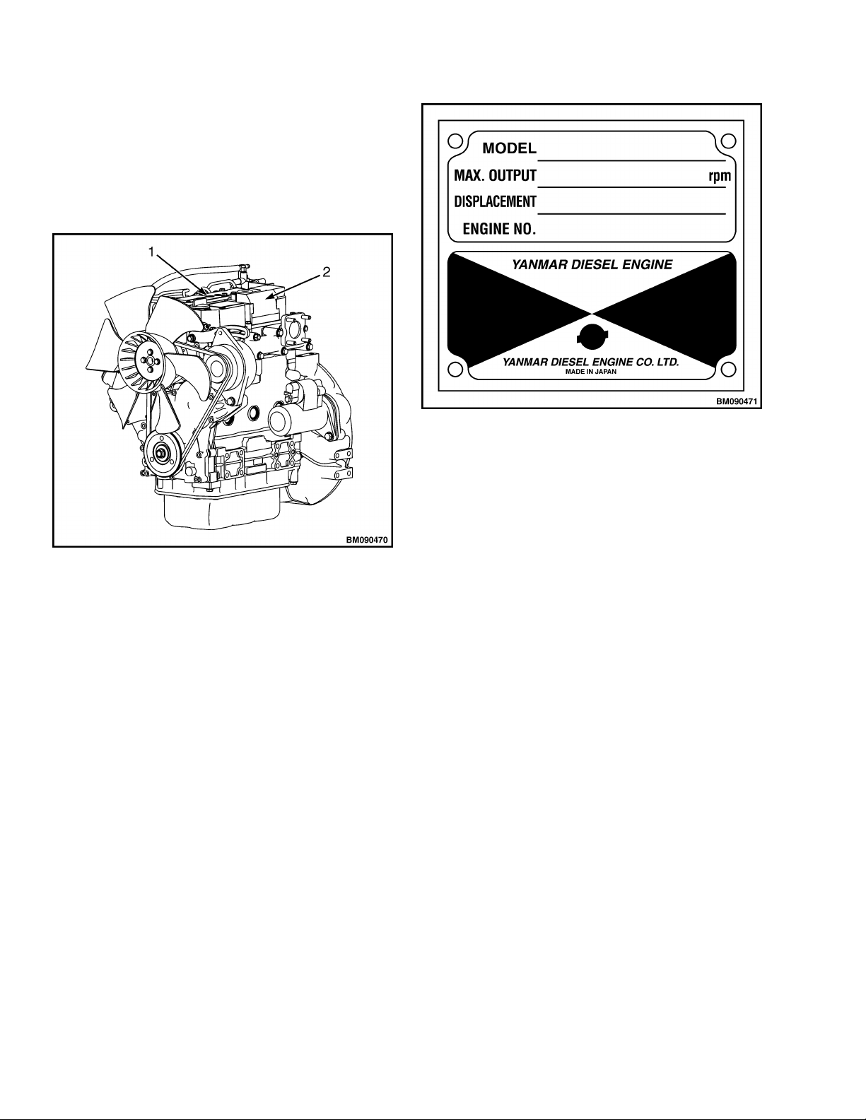
Location of Labels
The typical location of the emission control
information label is shown in Figure 2.
The typical location of the engine nameplate is
shown in Figure 2. The engine nameplate is shown
in Figure 3.
Figure 3. Engine Nameplate (Typical)
1. ENGINE NAMEPLATE
2. EMISSION CONTROL INFORMATION LABEL
Figure 2. Typical Location of Engine Labels
2

0600 SRM 1205 Engine Removal and Installation
Engine Removal and Installation
The procedures to remove and install the engine are
not included in this section.
See Frame 0100SRM1120 for lift truck models
H1.6-1.8FT, H2.0FTS (H30-35FT, H40FTS)
•
(F001)
H2.0-3.5FT (H40-70FT) (L177)
•
See Frame 0100SRM1735 for lift truck models
H1.6-1.8FT, H2.0FTS (H30-35FT, H40FTS)
•
(G001)
See Frame 0100SRM1672 for lift truck models
H2.0-3.5FT (H40-70FT) (N177)
•
See Frame 0100SRM1754 for lift truck models
H2.0-3.5FT (H40-70FT) (P177)
•
See Frame 0100SRM1423 for lift truck models
H2.0-2.5CT (H50CT) (A274)
•
See Frame 0100SRM1766 for lift truck models
H2.0-2.5CT (H50CT) (B274)
•
See Frame 0100SRM1984 for lift truck models
H2.0-3.0XT (H40-60XT) (A380)
•
3
Cylinder Head Assembly Repair 0600 SRM 1205
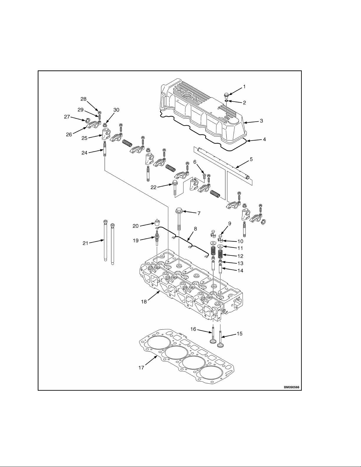
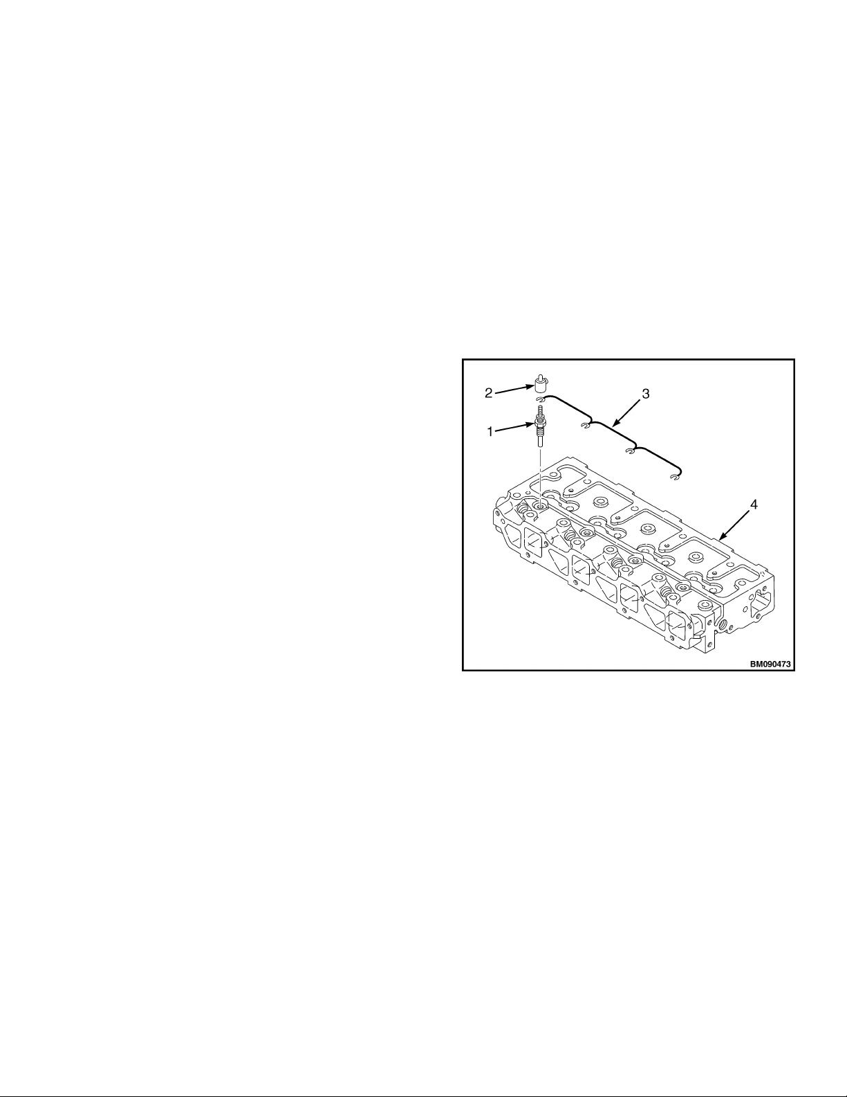
Cylinder Head Assembly Repair
Refer to Figure 4 for the cylinder head components.
Figure 4. Cylinder Head Components
4
0600 SRM 1205 Cylinder Head Assembly Repair
Legend for Figure 4.
1. VALVE COVER NUT
2. O-RING
3. VALVE COVER
4. VALVE COVER GASKET
5. ROCKER ARM SHAFT
6. ROCKER ARM SHAFT RETAINING SCREW
7. CYLINDER HEAD BOLT
8. GLOW PLUG HARNESS
9. VALVE CAP
10. VALVE KEEPERS
11. SPRING RETAINER
12. VALVE SPRING
13. VALVE STEM SEAL
14. VALVE GUIDE
15. INTAKE VALVE
GLOW PLUGS
Remove
Disconnect the negative battery cable at the
1.
battery.
Remove the glow plug cover from each of the
2.
glow plugs. See Figure 5.
Disconnect the glow plug harness from the glow
3.
plugs.
16. EXHAUST VALVE
17. CYLINDER HEAD GASKET
18. CYLINDER HEAD
19. GLOW PLUG
20. GLOW PLUG COVER
21. PUSH ROD
22. SUPPORT BRACKET BOLT
23. ROCKER ARM SHAFT SPRING
24. SUPPORT BRACKET STUD
25. SUPPORT BRACKET
26. ROCKER ARM
27. ROCKER ARM SHAFT RETAINING RING
28. VALVE ADJUSTING SCREW LOCK NUT
29. VALVE ADJUSTING SCREW
30. SUPPORT BRACKET NUT
Remove the glow plugs from the cylinder head.
4.
1. GLOW PLUG
2. COVER
3. WIRE HARNESS
4. CYLINDER HEAD
Figure 5. Glow Plugs
5
Cylinder Head Assembly Repair 0600 SRM 1205
Install
Install glow plugs into the cylinder head.
1.
Connect glow plug harness to glow plugs.
2.
Install glow plug covers on each glow plug.
3.
Connect negative battery cable.
4.
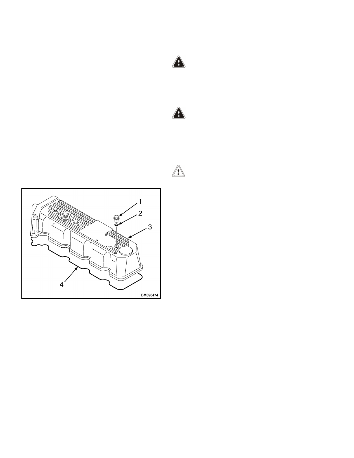
VALVE COVER
Remove
Remove valve cover nuts. See Figure 6.
1.
Inspect O-rings on each valve cover nut.
2.
Replace as needed.
Remove valve cover.
3.
Remove valve cover gasket and discard.
4.
Clean and Inspect
WARNING
Cleaning solvents can be flammable and toxic and
can cause skin irritation. When using cleaning
solvents, always follow the recommendations of
the manufacturer.
WARNING
Compressed air can move particles so that they
cause injury to the user or to other personnel.
Make sure that the path of the compressed air is
away from all personnel. Wear protective goggles
or a face shield to prevent injury to the eyes.
CAUTION
Use caution not to scratch the gasket mating
surfaces when cleaning the valve cover and
cylinder head.
Carefully remove all gasket residue from the valve
cover and cylinder head.
1. VALVE COVER NUT
2. O-RING
3. VALVE COVER
4. GASKET
Figure 6. Valve Cover
Clean valve cover in cleaning solvent. Dry valve
cover with compressed air. Inspect for wear, cracks,
and any other damage. If necessary, replace valve
cover.
Install
Lightly grease the new valve cover gasket.
1.
Place new valve cover gasket in the groove of
2.
the valve cover.
Place valve cover in position on the cylinder
3.
head.
Verify that the O-rings are installed on the
4.
valve cover nuts.
Install and tighten the valve cover nuts. Refer
5.
to Standard Torque Specifications.
6

0600 SRM 1205 Cylinder Head Assembly Repair
Remove the bolt and locking nuts that retain
ROCKER ARM ASSEMBLY
Remove
Remove valve cover. See Valve CoverRemove.
1.
2.
the rocker arm assembly support brackets to
the cylinder head. See Figure 7.
1. SUPPORT BRACKET NUT
2. VALVE ADJUSTING SCREW LOCK NUT
3. VALVE ADJUSTING SCREW
4. ROCKER ARM SHAFT
5. ROCKER ARM SHAFT RETAINING RING
6. SUPPORT BRACKET STUD
Figure 7. Rocker Arm Assembly
7. SUPPORT BRACKET
8. ROCKER ARM SHAFT SPRING
9. ROCKER ARM
10. SUPPORT BRACKET BOLT
11. ROCKER ARM SHAFT RETAINING SCREW
12. CYLINDER HEAD
7
Cylinder Head Assembly Repair 0600 SRM 1205
Lift the rocker arm shaft assembly from the
3.
cylinder head.
NOTE: Mark the push rods so they can be
reinstalled in original location during reassembly.
Remove the push rods from the cylinder head.
4.
Disassemble
Remove the rocker arm shaft retaining screw
1.
from the support bracket that secures the
rocker arm shaft. See Figure 7.
Remove the retaining rings from the ends of
2.
the rocker arm shaft.
NOTE: Mark the rocker arms so they can be
reinstalled in original location during reassembly.
NOTE: The rocker arm shaft fits tightly in the
rocker arm support brackets. Clamp the support
bracket in a padded vise and twist and pull the
rocker arm shaft to remove the shaft.
Slide rocker arm shaft out of the rocker arm
3.
support brackets, springs, and rocker arms.
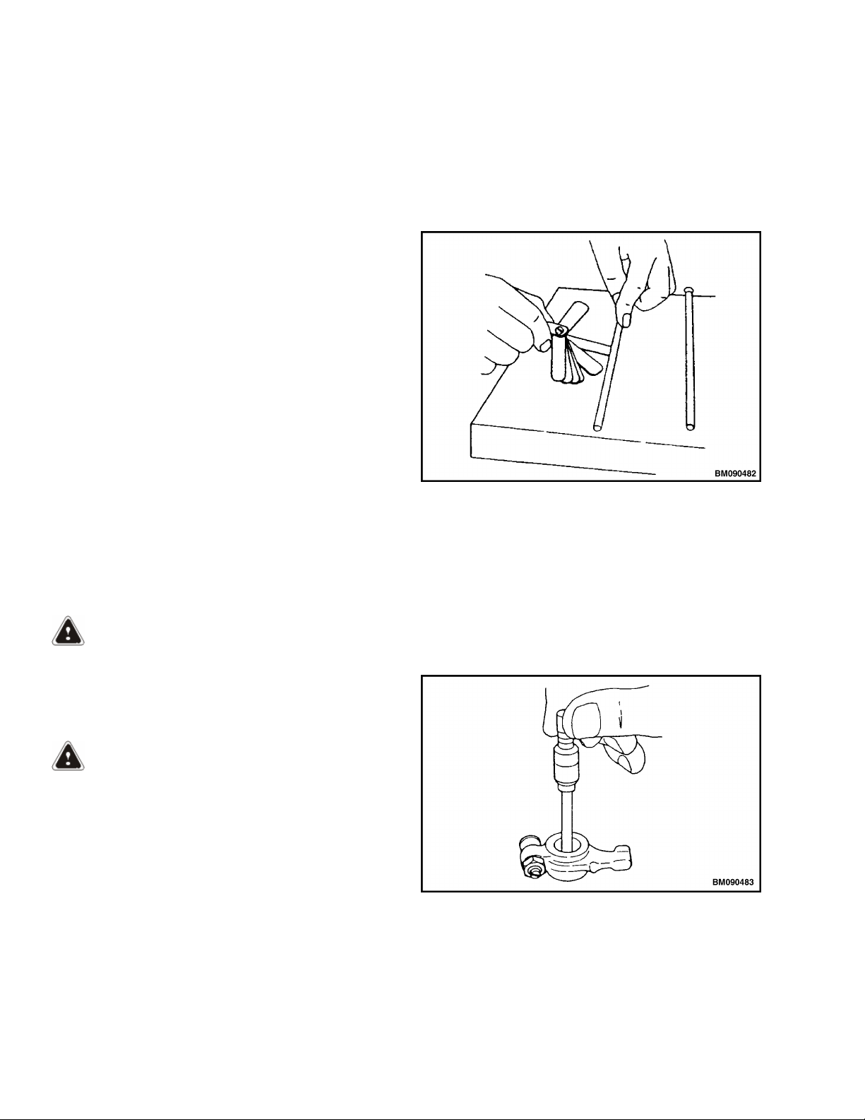
Roll push rods until a gap can be observed
2.
between a portion of the push rod and the
surface of the inspection block.
Use a feeler gauge to measure the gap. Refer to
3.
the Engine Specifications for the service limit.
See Figure 8.
Figure 8. Push Rod Inspection
If necessary, remove valve adjusting screw and
4.
lock nut from the rocker arms.
Clean and Inspect
WARNING
Cleaning solvents can be flammable and toxic and
can cause skin irritation. When using cleaning
solvents, always follow the recommendations of
the manufacturer.
WARNING
Compressed air can move particles so that they
cause injury to the user or to other personnel.
Make sure that the path of the compressed air is
away from all personnel. Wear protective goggles
or a face shield to prevent injury to the eyes.
Clean all parts in cleaning solvent. Dry parts with
compressed air. Inspect for wear, cracks, and any
other damage. Replace all parts as needed.
Rocker Arm Assembly
Rocker Arm and Support Bracket Inside
Diameter - Use a test indicator and micrometer to
determine if the inside diameter of all the rocker
arm support brackets and rocker arms are within
limits. Refer to the Engine Specifications for the
service limit. See Figure 9.
Figure 9. Rocker Arm Inside Diameter
Push Rods
Place push rods on a flat inspection block.
1.
8
Shaft Outside Diameter - Use a micrometer to
measure the rocker arm shaft outside diameter.
Refer to the Engine Specifications for the service
limit. See Figure 10.
0600 SRM 1205 Cylinder Head Assembly Repair
Tighten rocker arm shaft retaining bolt and
5.
nuts.
Tighten rocker arm shaft alignment screw.
6.
Adjust valve lash. See Valve Clearance
7.
Adjustments.
Install valve cover. See Valve CoverInstall.
8.
VALVE CLEARANCE ADJUSTMENTS
NOTE: Make measurements and adjustments while
Figure 10. Rocker Arm Shaft Outside Diameter
Assemble
NOTE: The rocker arm shaft fits tightly in the
rocker arm support brackets. Clamp the rocker arm
shaft in a padded vise and twist and push the
support brackets onto the rocker arm shaft.
NOTE: To properly align the rocker arm shaft with
the support brackets, first install the rocker arm
shaft support bracket with the hole for the shaft
alignment screw. Align the hole in the rocker arm
shaft and the hole in the support bracket. Install
the alignment screw. See Figure 7.
Lubricate the rocker arm shaft. Slide the rocker
1.
arm support brackets, springs, and rocker arms
onto the shaft.
Position the rocker arm assembly on a flat
2.
surface. Install the retaining rings onto the
ends of the rocker arm shaft. See Figure 7.
If removed, install the valve adjusting screws
3.
and lock nuts.
Install
Install push rods.
1.
Place rocker arm assembly in position on the
2.
cylinder head.
Install and hand tighten the rocker arm shaft
3.
retaining bolt and nuts.
Align push rods with their respective rocker
4.
arms.
the engine is cold.
NOTE: The cylinder to be adjusted first does not
have to be the number one cylinder. Select and
adjust the cylinder where the piston is the nearest
to top dead center (TDC) after rotating and make
the adjustment for the other cylinders in the order
of the ignition by turning the crankshaft 180
degrees each time.
Remove valve cover. See Valve CoverRemove.
1.
NOTE: The number one piston position is on the
flywheel end of the engine, opposite side of the
radiator, and the ignition order is 1 - 3 - 4 - 2 at 180
degree intervals.
NOTE: Since intake and exhaust valve rocker arms
are operated the same and there is a clearance
between rocker arm and valve generally at top dead
center, the position can be checked by means of the
play when the arm head is held with a hand. Also,
see that the crankshaft pulley top mark is
positioned at zero on the timing scale. If there is no
valve clearance, inspection in the disassembled
state is necessary since the valve seat may be worn
abnormally.
Rotate crankshaft clockwise, as seen from the
2.
radiator side, to bring the number one piston to
top dead center (TDC) while watching the
rocker arm motion, timing scale, and top mark
position of the crankshaft pulley. (Position
where both the intake and exhaust valves are
closed.)
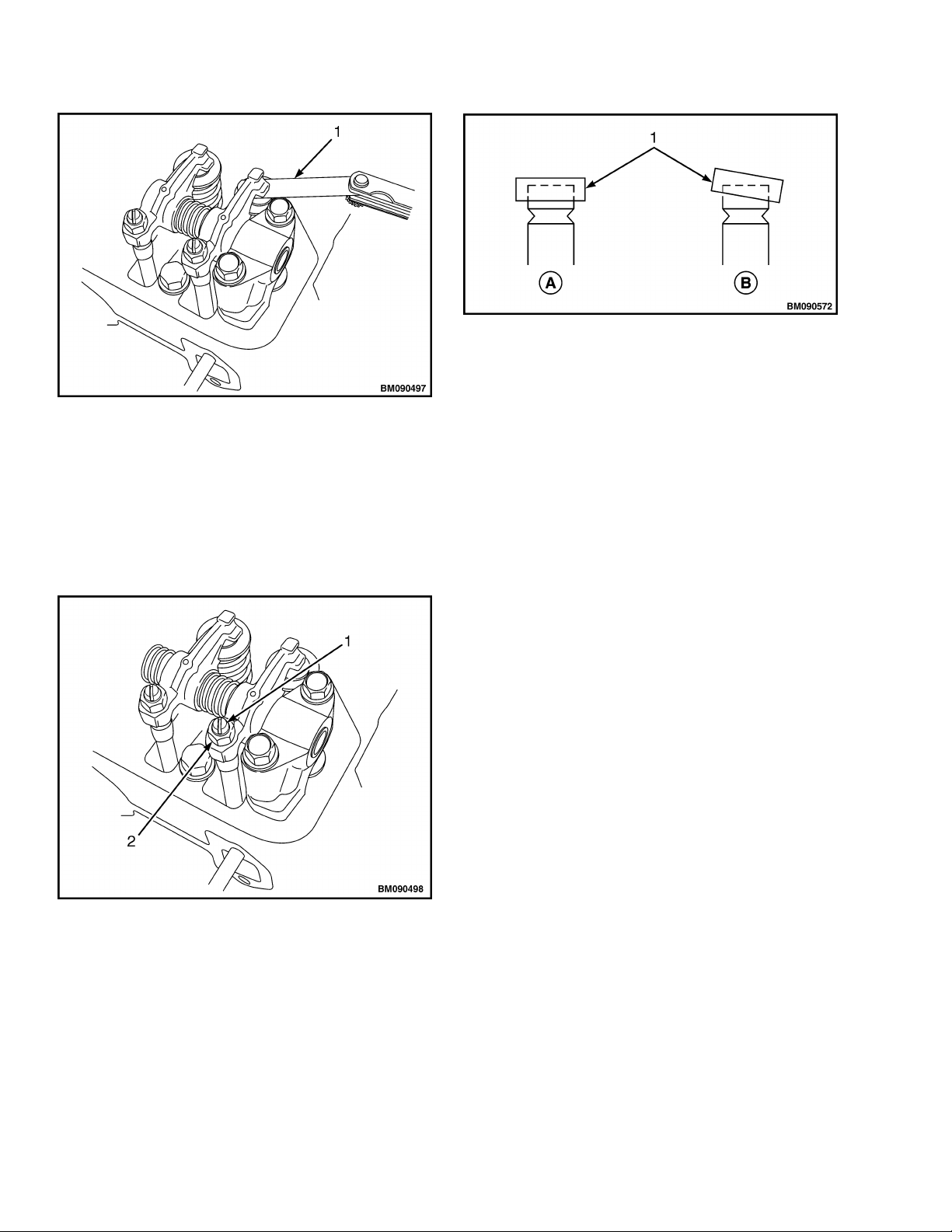
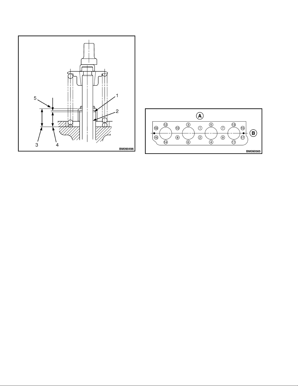
Insert a feeler gauge between the rocker arm
3.
and valve cap. See Figure 11. Record the
measured valve clearance. The valve clearance
should be between
0.15 to 0.25 mm (0.006 to 0.010 in.).
9
Cylinder Head Assembly Repair 0600 SRM 1205
A. NORMAL
B. ABNORMAL
1. VALVE CAP
1. FEELER GAUGE
Figure 11. Valve Clearance Measurement
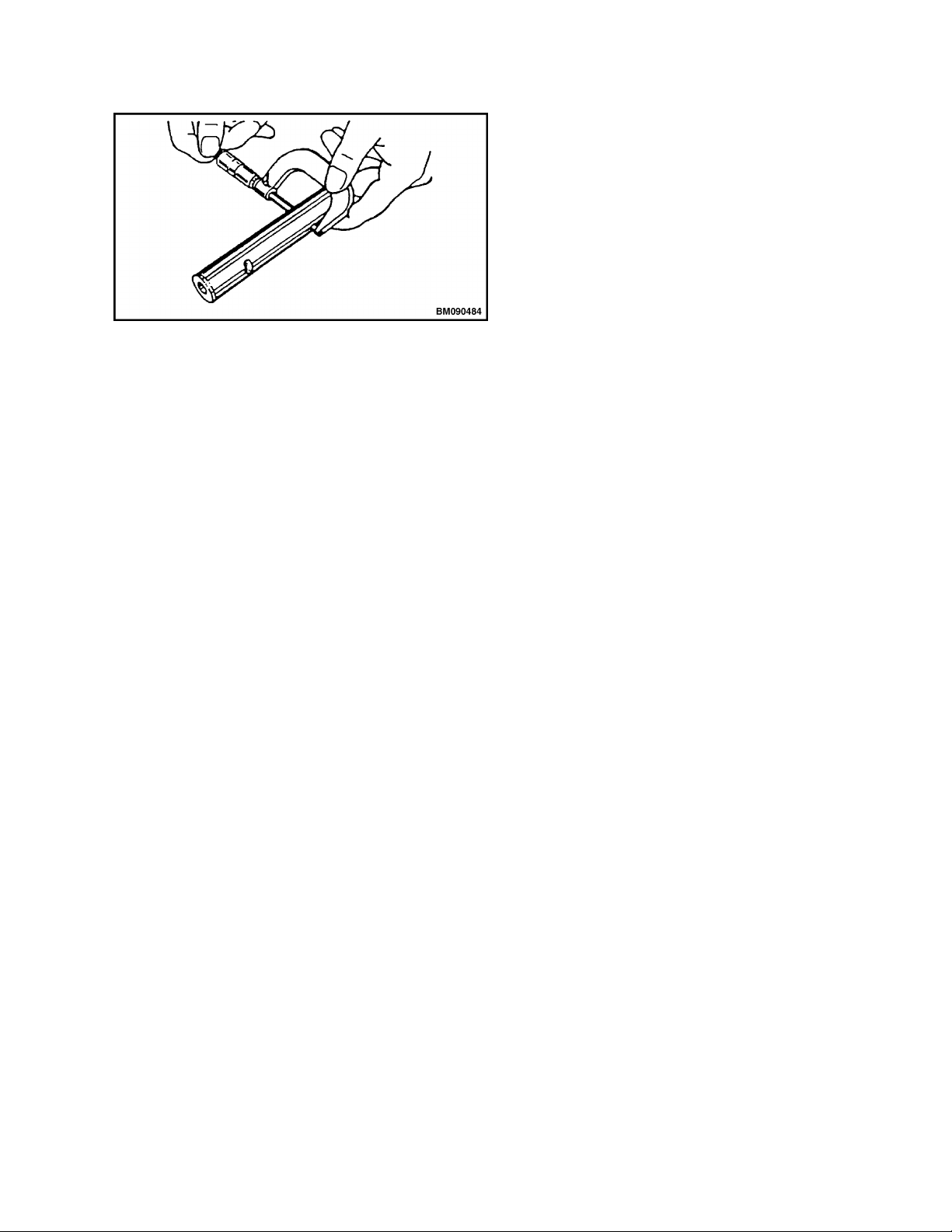
If adjustment is needed, loosen the valve
4.
adjusting screw lock nut and valve adjusting
screw on the rocker arm (see Figure 12) and
check the valve for any inclination of valve cap,
entrance of dirt, or wear. See Figure 13.
1. VALVE ADJUSTING SCREW
2. VALVE ADJUSTING SCREW LOCK NUT
Figure 13. Valve Cap Check
NOTE: There is a tendency for the clearance to
decrease slightly when the lock nut is tightened. It
is suggested that you make the clearance
adjustment slightly on the loose side before
tightening the lock nut.
Insert a 0.2 mm (0.008 in.) feeler gauge
5.
between the rocker arm and valve cap and
adjust the clearance so there is a slight drag on
the feeler gauge when sliding it between the
rocker arm and valve cap. Tighten the valve
adjusting screw lock nut and recheck the
clearance. The valve clearance should be
between 0.15 to 0.25 mm (0.006 to 0.010 in.).
Apply clean engine oil to the contact surface
6.
between the adjusting screw and push rod.
Turn the crankshaft 180 degrees and make the
7.
measurement and adjustment for the number
three cylinder. Then turn the crankshaft 180
degrees and make the measurement and
adjustment for the number four cylinder. Then
turn the crankshaft 180 degrees and make the
measurement and adjustment for the number 2
cylinder.
Install the valve cover. See Valve CoverInstall.
8.
Figure 12. Valve Clearance Adjustment
10
0600 SRM 1205 Cylinder Head Assembly Repair
CYLINDER HEAD ASSEMBLY
Remove
Disconnect negative battery cable at the
1.
battery.
Remove alternator. See Electrical Equipment
2.
Repair.
Remove water pump. See Cooling System
3.
Repair.
Disconnect air intake hose from the intake
4.
manifold.
Remove glow plugs. See Glow Plugs, Remove.
5.
Remove fuel injectors and high pressure lines.
6.
See Fuel System Repair.
If equipped, remove the pull actuator and
7.
mounting bracket. See Fuel System Repair.
Disconnect the electrical connector for the fuel
8.
filter sensor.
Tag and disconnect the fuel hoses from the fuel
9.
filter.
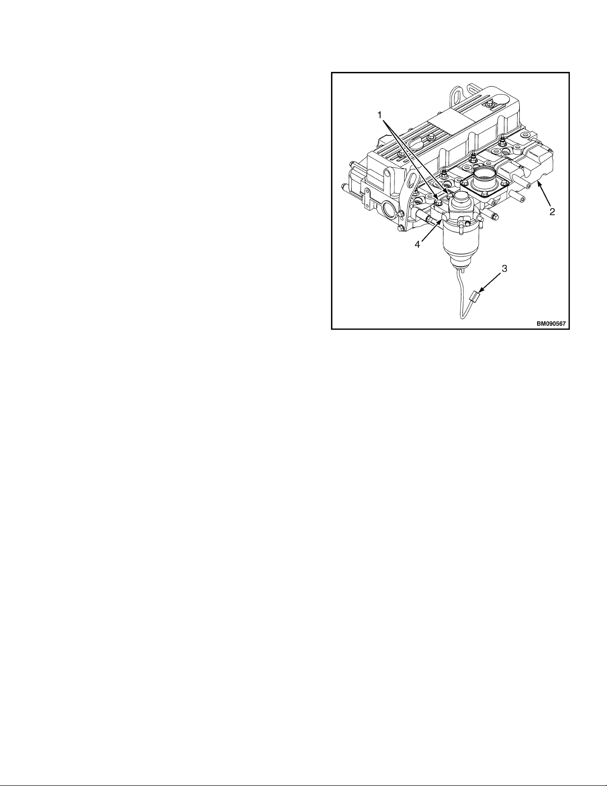
Remove the bolts retaining the fuel filter
10.
housing assembly to the intake manifold and
remove the fuel filter housing assembly. See
Figure 14.
1. BOLTS
2. INTAKE MANIFOLD
3. FUEL SENSOR ELECTRICAL CONNECTOR
4. FUEL FILTER HOUSING ASSEMBLY
Figure 14. Fuel Filter Housing Assembly
11
Cylinder Head Assembly Repair 0600 SRM 1205
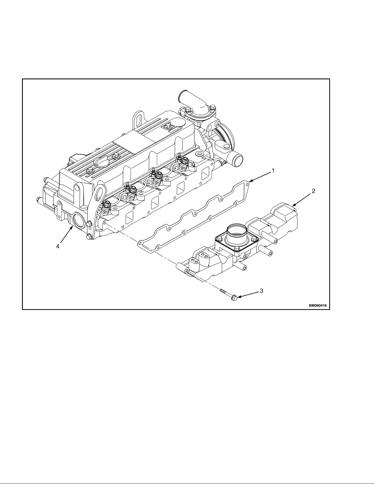
Remove the bolts retaining the intake manifold
11.
to the cylinder head and remove the intake
manifold and gasket. Discard gasket. See
Figure 15.
1. GASKET
2. INTAKE MANIFOLD
12
3. BOLT
4. CYLINDER HEAD
Figure 15. Intake Manifold

0600 SRM 1205 Cylinder Head Assembly Repair
Remove the nuts retaining the exhaust pipe to
12.
the exhaust manifold and disconnect the
exhaust pipe from the exhaust manifold.
Remove the bolts retaining the exhaust
13.
manifold to the cylinder head and remove the
exhaust manifold and gasket. Discard gasket.
See Figure 16.
1. CYLINDER HEAD
2. BOLT
3. EXHAUST MANIFOLD
4. GASKET
Figure 16. Exhaust Manifold
13
Cylinder Head Assembly Repair 0600 SRM 1205
Remove the valve cover. See Valve Cover,
14.
Remove.
Remove the rocker arm assembly. See Rocker
15.
Arm Assembly, Remove.
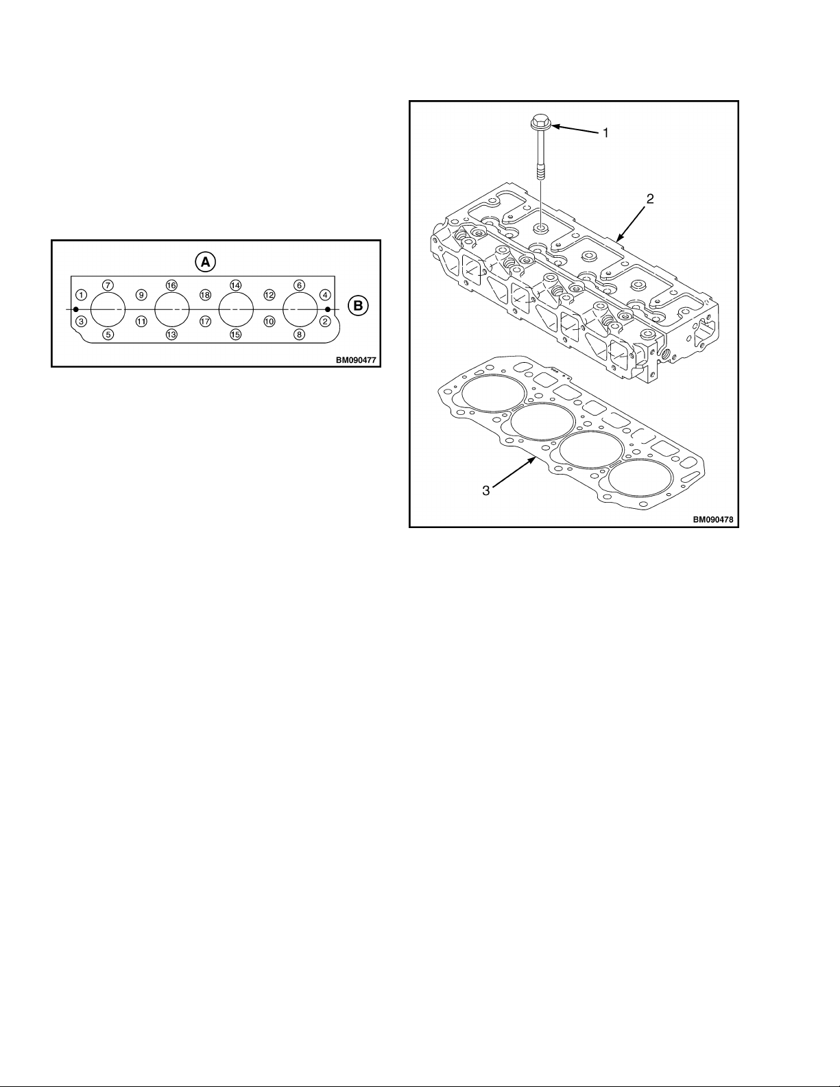
Loosen the cylinder head bolts following the
16.
sequence shown in Figure 17.
A. CAMSHAFT SIDE
B. FAN SIDE
Figure 17. Cylinder Head Bolt Loosening Sequence
Remove the cylinder head bolts. See Figure 18.
17.
1. BOLT
2. CYLINDER HEAD
3. GASKET
Figure 18. Cylinder Head and Gasket
Lift the cylinder head away from the cylinder
18.
block. Place the cylinder head on a work bench
to prevent damage to the combustion chamber.
Remove the cylinder head gasket and discard.
19.
14

0600 SRM 1205 Cylinder Head Assembly Repair
Slowly release the tension on the valve spring.
Disassemble
3.
Valves and Valve Springs, Remove
Using a valve spring compressor tool, compress
1.
one of the valve springs. See Figure 19.
Figure 19. Valve Spring Compressor
Remove the valve keepers and the valve cap
2.
from the end of the valve. See Figure 20.
Remove the spring retainer, valve spring, and
4.
valve stem seal.
Repeat this procedure until all intake and
5.
exhaust valve springs and valve stem seals are
removed.
NOTE: If existing valves are going to be reinstalled
in the cylinder head, mark the valves so they can be
installed in their original location.
Turn the cylinder head so the exhaust port side
6.
faces down. Remove the intake and exhaust
valves from the cylinder head.
Valve Guides, Remove
Using a drift pin and hammer, drive the valve
guides out of the cylinder head. See Figure 21.
1. VALVE CAP
2. VALVE KEEPERS
3. SPRING RETAINER
4. SPRING
5. VALVE STEM SEAL
6. VALVES
7. CYLINDER HEAD
Figure 20. Valves and Valve Springs
1. VALVE GUIDE
2. CYLINDER HEAD
Figure 21. Valve Guides
Clean and Inspect
WARNING
Cleaning solvents can be flammable and toxic and
can cause skin irritation. When using cleaning
solvents, always follow the recommendations of
the manufacturer.
15
Cylinder Head Assembly Repair 0600 SRM 1205
cylinder head for scratches, cracks, or any other
WARNING
Compressed air can move particles so that they
cause injury to the user or to other personnel.
Make sure that the path of the compressed air is
away from all personnel. Wear protective goggles
or a face shield to prevent injury to the eyes.
CAUTION
Any part which is found defective as a result of
inspection or any part whose measured value does
not satisfy the standard or limit must be replaced.
damage. Repair or replace as needed.
Thoroughly clean all components using a nonmetallic brush and cleaning solvent. Dry the parts
with compressed air. Each part must be free of
carbon, metal filings, and other debris.
Visually inspect the parts. Replace any parts that
are obviously discolored, heavily pitted, or otherwise
damaged. Replace parts that do not meet the
specified limit.
Cylinder Head
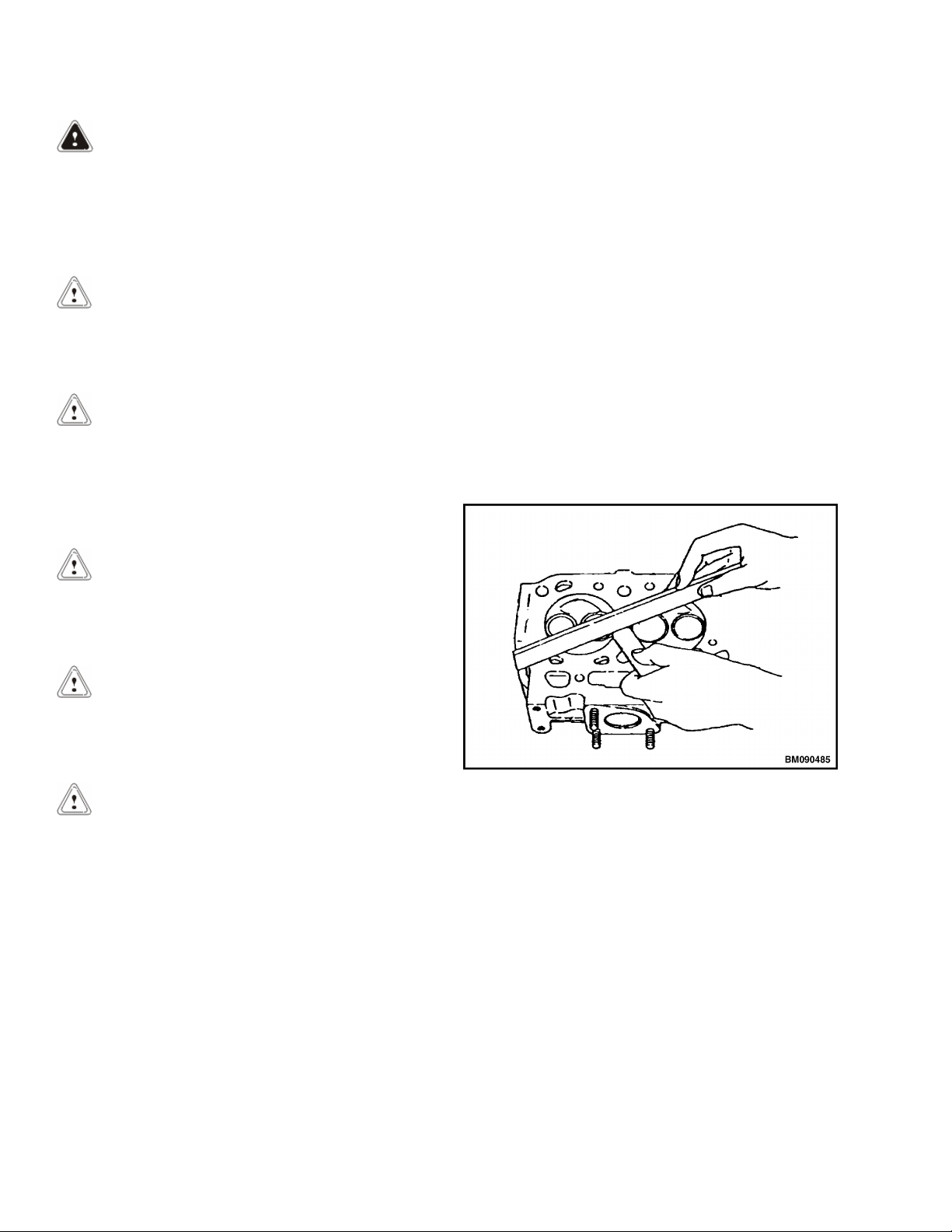
Place the cylinder head flat and inverted
1.
(combustion side up) on the work bench.
CAUTION
Any part determined to not meet the service
standard or limit before the next service, as
determined from the state of current rate of wear,
should be replaced even though the part currently
meets the service standard limit.
CAUTION
Use caution not to scratch the gasket mating
surfaces when cleaning the exhaust manifold and
cylinder head.
CAUTION
Use caution not to scratch the gasket mating
surfaces when cleaning the intake manifold and
cylinder head.
CAUTION
Use caution not to scratch the gasket mating
surfaces when cleaning the cylinder head and
cylinder block.
Use a straight edge and feeler gauge to
2.
measure the amount of cylinder head
distortion. Refer to the Engine Specifications
for the service limit. See Figure 22.
Figure 22. Cylinder Head Distortion Check
Use the Magnaflux method and inspect the
3.
cylinder head for cracks. Replace the cylinder
head if evidence of fractures are found.
Carefully remove all gasket residue from the
exhaust manifold and cylinder head. Inspect the
exhaust manifold for scratches, cracks, or any other
damage. Repair or replace as needed.
Carefully remove all gasket residue from the intake
manifold and cylinder head. Inspect the intake
manifold for scratches, cracks, or any other damage.
Repair or replace as needed.
Carefully remove all gasket residue from the
cylinder head and cylinder block. Inspect the
16
Valve Guides
Visually inspect the valve guides for distortions,
scoring, or other damage.
Use a test indicator and micrometer to measure the
inside diameter at each end of the valve guide. Refer
to the Engine Specifications for the service limit.
0600 SRM 1205 Cylinder Head Assembly Repair
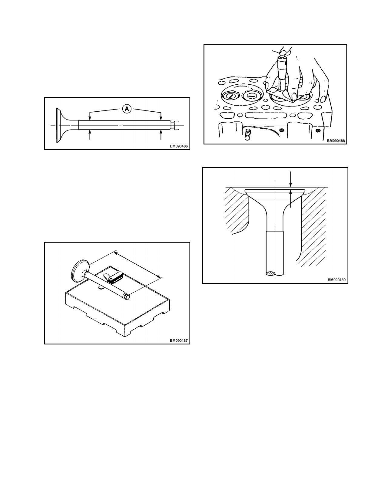
Valves
Valve Stem Diameter - Use a micrometer to
measure the valve stem diameter. Measure the
valve stem near the combustion end and near the
opposite end. Refer to the Engine Specifications for
the service limit. See Figure 23.
A. MEASUREMENT POINTS
Figure 23. Valve Stem Diameter Measurement
Points
Valve Stem Straightness - Place the valve stem
on a flat surface. Roll the valve until a gap can be
observed between a portion of the valve stem and
the flat surface. Use a feeler gauge to measure the
gap. Refer to the Engine Specifications for the
service limit. See Figure 24.
Figure 24. Valve Stem Straightness Check
Figure 25. Valve Sink Measurement
Figure 26. Valve Sink
Valve Seat
Always check the clearance between the valve and
valve guide before correcting the valve seat. See
Figure 27. If the clearance exceeds the limit, replace
the valve or valve guide to bring the clearance
within the limit.
Valve Sink
Insert the valves into their proper places in the
cylinder head and press them down until they are
fully seated. Using a depth micrometer, measure
the difference between the cylinder head surface
and the combustion surface of each exhaust and
intake valve. Refer to the Engine Specifications for
the service limit. See Figure 25 and Figure 26.
17
Cylinder Head Assembly Repair 0600 SRM 1205
Figure 28. Spring Squareness Check
Free Length - Use a caliper to measure the length
of the spring. Refer to the Engine Specifications for
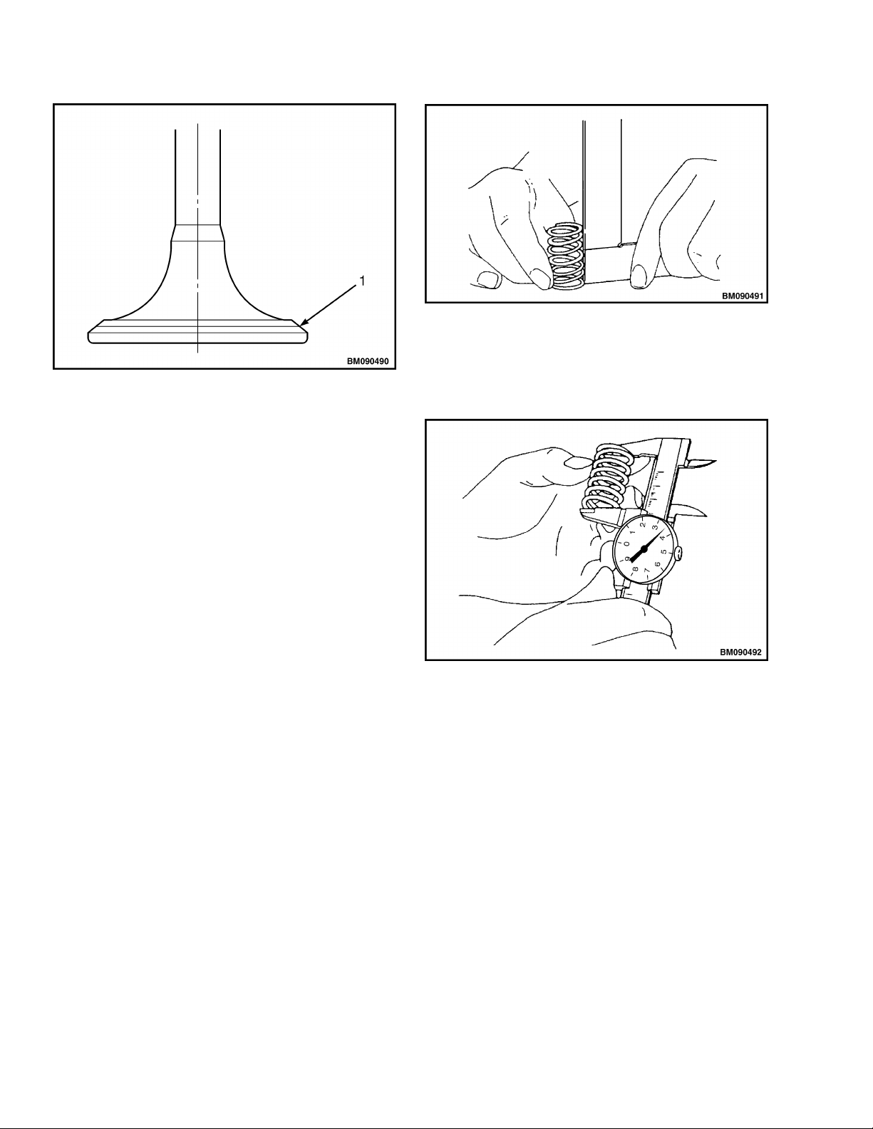
1. VALVE SEAT
Figure 27. Valve Seat
Roughness or burrs will cause poor seating of a
valve. Visually inspect the seating of each valve and
determine if lapping or grinding is needed. Grinding
is needed if the cylinder head's seat width exceeds
standard limits. Refer to the Engine Specifications
for the service limit.
the service limit. See Figure 29.
Lap the valve seat and the cylinder head with a
mixture of valve compound and engine oil.
If the valve requires grinding, lap the valve after
grinding. Be sure to thoroughly wash the parts to
remove all grinding powder or compound.
Valve Springs
Inspect the valve springs. If damage or corrosion is
seen, or if measurements exceed the specified limits,
replace the springs.
Fractures - Check for fractures on the inside and
outside portions of the springs. If the valve spring is
fractured, replace the spring.
Corrosion - Check for corrosion of spring material
caused by oxidation.
Squareness - Use a flat surface and a square to
check each spring for squareness. Refer to the
Engine Specifications for the service limit. See
Figure 28.
Figure 29. Spring Free Length Check
Assemble
Valve Guides, Install
The valve guides are installed into the cylinder
1.
head with an extremely tight press fit. Before
installing the valve guides, place the valve
guides in a freezer for at least twenty minutes.
This will cause the valve guides to contract,
making it easier to install the valve guides into
place.
Immediately after removing the valve guides
2.
from the freezer, insert the valve guides in
their proper positions in the cylinder head.
18
0600 SRM 1205 Cylinder Head Assembly Repair
Finish installing the valve guides into the
3.
cylinder head to the proper height using a
special tool, valve guide installation tool. See
Figure 30.
1. VALVE STEM SEAL INSTALLATION TOOL
2. VALVE STEM SEAL
1. VALVE GUIDE INSTALLATION TOOL
2. CYLINDER HEAD
3. VALVE GUIDE
3. VALVE GUIDE
4. CYLINDER HEAD
Figure 31. Valve Stem Seal Installation
Figure 30. Valve Guide Installation
Valves and Valve Springs, Install
Place the cylinder head assembly on the
1.
exhaust port side.
Place all the valves in their proper positions, as
2.
marked when disassembled, in the cylinder
head.
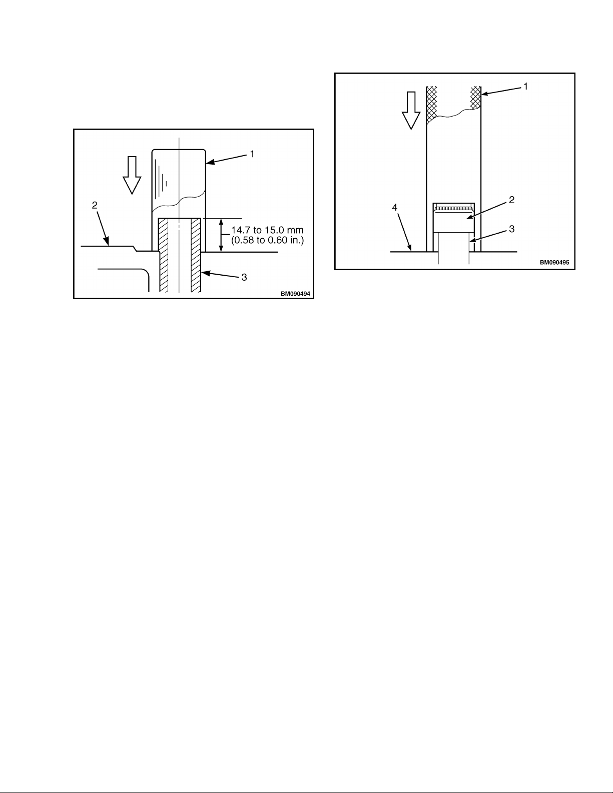
Apply clean engine oil to the lip of the valve
3.
stem seal. Using a special tool, valve stem seal
installation tool, insert a new valve stem seal
on each of the valves. See Figure 31.
Measure the distance from the cylinder head to
4.
the valve stem seal. Refer to the Engine
Specifications for the clearance specifications.
See Figure 32.
19
Cylinder Head Assembly Repair 0600 SRM 1205
Position the cylinder head on the cylinder head
3.
gasket and cylinder block.
Lightly oil the threads of the cylinder head
4.
bolts.
Install the cylinder head bolts and tighten the
5.
cylinder head bolts to
49 to 59 N•m (36 to 43 lbf ft) in the sequence
shown in Figure 33. Then tighten the cylinder
head bolts to 103 to 113 N•m (76 to 83 lbf ft) in
the same sequence.
1. VALVE STEM SEAL
2. VALVE GUIDE
3. VALVE GUIDE PROTECTION
4. VALVE STEM SEAL PROTECTION
5. CLEARANCE
Figure 32. Valve Stem Seal Clearance
Place the cylinder head on the work bench with
5.
the combustion chamber facing down. Install
the valve springs and valve spring retainers.
See Figure 20.
Using the valve compressor tool, compress the
6.
valve spring.
Install the valve keepers and slowly release the
7.
tension in the valve spring.
Install the valve cap.
8.
Repeat these procedures until all the intake
9.
and exhaust valves are installed.
Install
Carefully clean the combustion surface of the
1.
cylinder head and the top surface of the
cylinder block.
Place a new cylinder head gasket on the
2.
cylinder block. See Figure 18.
A. CAMSHAFT SIDE
B. FAN SIDE
Figure 33. Cylinder Head Torque Sequence
Install the push rods and rocker arm assembly.
6.
See Rocker Arm Assembly, Install.
Install the valve cover. See Valve Cover,
7.
Install.
Place a new gasket and the exhaust manifold in
8.
position on the cylinder head and install the
exhaust manifold retaining bolts.
Connect the exhaust pipe to the exhaust
9.
manifold and install retaining nuts.
Place a new gasket and the intake manifold in
10.
position on the cylinder head and install the
intake manifold retaining bolts.
Place the fuel filter housing assembly in
11.
position on the intake manifold and install
retaining bolts.
Connect the fuel hoses to the fuel filter.
12.
Connect the electrical connector for the fuel
13.
filter sensor.
If equipped, install the pull actuator and
14.
mounting bracket. See Fuel System Repair.
20
0600 SRM 1205 Cylinder Head Assembly Repair
Install the fuel injectors and high pressure
15.
lines. See Fuel System Repair.
Install the glow plugs. See Glow Plugs, Install.
16.
Connect the air intake hose to the intake
17.
manifold.
Start engine and check for leaks.
23.
Change engine oil and oil filter. See
24.
Lubrication System Repair, Engine Oil and Oil
Filter Change.
Install water pump. See Cooling System
18.
Repair.
Install alternator. See Electrical Equipment
19.
Repair.
CAUTION
Additives may damage the cooling system. Before
using additives, contact your local Hyster dealer.
Fill cooling system with coolant. See Periodic
20.
Maintenance Manual for your lift truck for
the correct coolant amount and type.
Install radiator cap.
21.
Connect negative battery cable.
22.
WARNING
During engine operation, be careful not to touch
the fan, pulleys, or drive belts. Contact with these
parts can cause serious injury.
WARNING
The radiator or other parts of the cooling system
may be hot or under pressure and can cause
serious injury.
WARNING
DO NOT remove the radiator cap from the radiator
when the engine is hot. When the radiator cap is
removed, pressure will release from the coolant
system. If the coolant system is hot, the steam and
boiling coolant can cause severe burns.
WARNING
The radiator or other parts of the cooling system
may be hot or under pressure and can cause
serious injury. Wait 30 minutes for the radiator and
engine to cool before performing maintenance to
the cooling system. After 30 minutes, do a touch
test by touching the radiator with your hand. If the
radiator is still hot to the touch, wait another 30
minutes before attempting any maintenance to the
cooling system.
CAUTION
Additives may damage the cooling system. Before
using additives, contact your local Hyster dealer.
Stop engine. If coolant is hot, allow engine time
25.
to cool. Check coolant level and fill as required
between the ADD and FULL marks on the
coolant reservoir.
21
Timing Gear Case and Timing Gears Repair 0600 SRM 1205
Timing Gear Case and Timing Gears Repair
TIMING GEAR CASE COVER
Remove
Remove the engine.
1.
See Frame 0100SRM1120 for lift truck models
H1.6-1.8FT, H2.0FTS (H30-35FT, H40FTS)
•
(F001)
H2.0-3.5FT (H40-70FT) (L177)
•
See Frame 0100SRM1735 for lift truck models
H1.6-1.8FT, H2.0FTS (H30-35FT, H40FTS)
•
(G001)
See Frame 0100SRM1423 for lift truck models
H2.0-2.5CT (H50CT) (A274)
•
See Frame 0100SRM1672 for lift truck model
H2.0-3.5FT (H40-70FT) (N177)
•
See Frame 0100SRM1754 for lift truck models
H2.0-3.5FT (H40-70FT) (P177)
•
See Frame 0100SRM1766 for lift truck models
H2.0-2.5CT (H50CT) (B274)
•
See Frame 0100SRM1984 for lift truck models
H2.0-3.0XT (H40-60XT) (A380)
•
Install engine onto engine stand.
2.
Remove the coolant fan, V-belt, and water
3.
pump. See Cooling System Repair.
Remove the bolt and washer retaining the
4.
crankshaft pulley.
Using a gear puller, remove the crankshaft
5.
pulley.
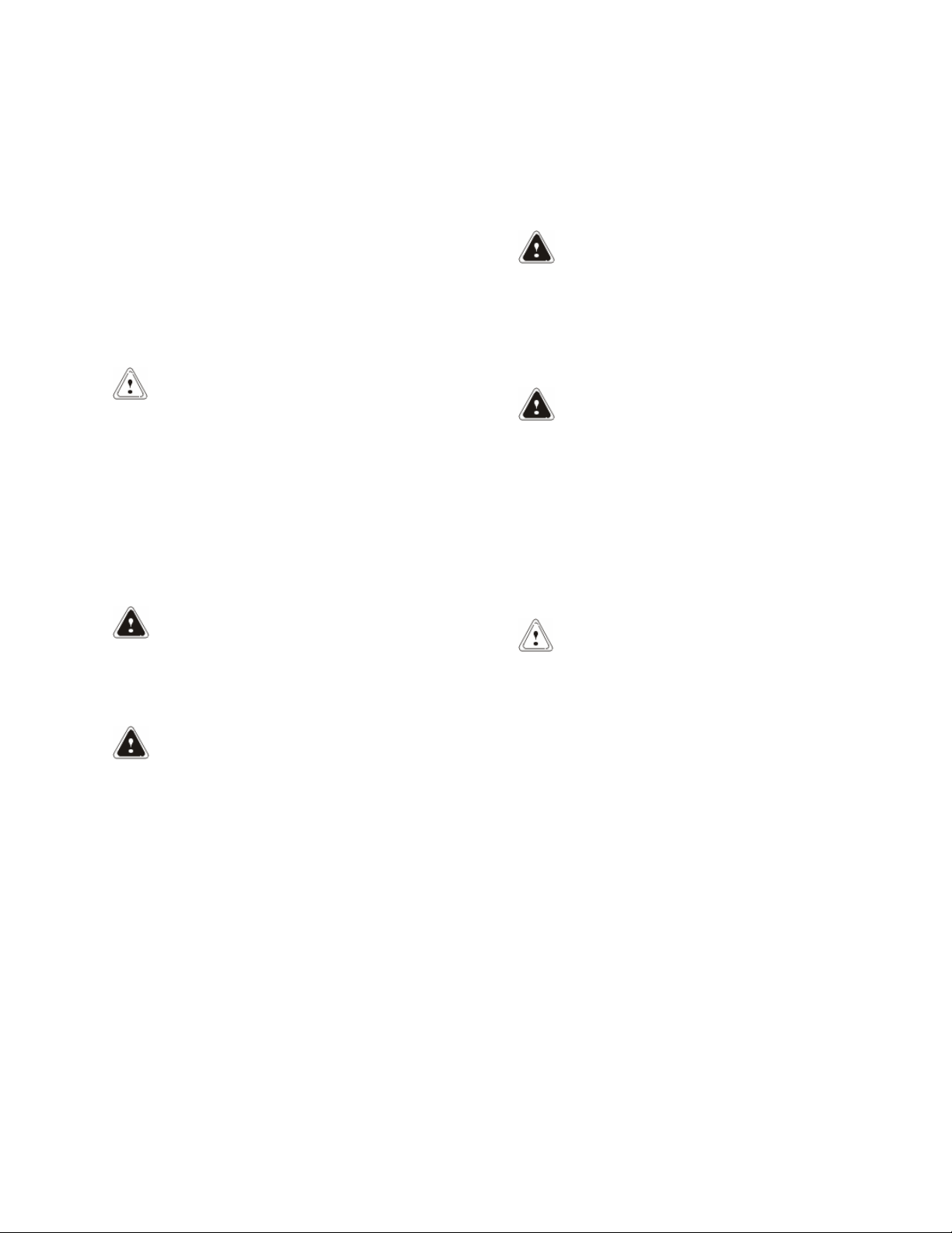
1. TIMING GEAR CASE
2. TIMING GEAR CASE COVER
3. BOLT
4. FRONT OIL SEAL
Figure 34. Timing Gear Case Cover
Remove the timing gear case cover.
7.
If necessary, remove the front oil seal from the
8.
timing gear case cover. See Figure 34.
Clean and Inspect
WARNING
Cleaning solvents can be flammable and toxic and
can cause skin irritation. When using cleaning
solvents, always follow the recommendations of
the manufacturer.
Remove the bolts retaining the timing gear
6.
case cover. See Figure 34.
22
WARNING
Compressed air can move particles so that they
cause injury to the user or to other personnel.
Make sure that the path of the compressed air is
away from all personnel. Wear protective goggles
or a face shield to prevent injury to the eyes.
0600 SRM 1205 Timing Gear Case and Timing Gears Repair
Clean all old sealant from the timing gear case
cover and the timing gear case. Clean the timing
gear case cover in cleaning solvent. Dry the timing
gear case cover with compressed air. Inspect for
wear, cracks, and any other damage. If necessary,
replace timing gear case cover.
Install
Apply a continuous bead of Three Bond Liquid
1.
Gasket, Hyster Part Number 1599478 , to the
outside diameter of a new front oil seal.
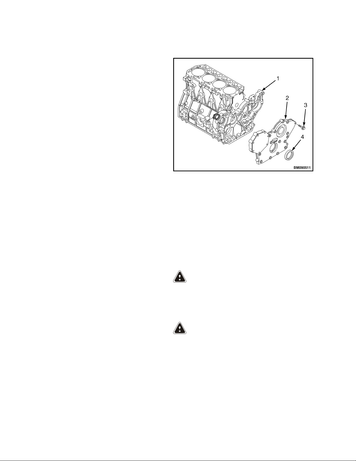
Using a special tool, install the new front oil
2.
seal into the timing gear case cover. Apply
lithium grease to the lip of the front oil seal.
See Figure 35.
Install the engine.
7.
See Frame 0100SRM1120 for lift truck models
H1.6-1.8FT, H2.0FTS (H30-35FT, H40FTS)
•
(F001)
H2.0-3.5FT (H40-70FT) (L177)
•
See Frame 0100SRM1735 for lift truck models
H1.6-1.8FT, H2.0FTS (H30-35FT, H40FTS)
•
(G001)
See Frame 0100SRM1423 for lift truck models
H2.0-2.5CT (H50CT) (A274)
•
See Frame 0100SRM1672 for lift truck model
H2.0-3.5FT (H40-70FT) (N177)
•
See Frame 0100SRM1754 for lift truck models
H2.0-3.5FT (H40-70FT) (P177)
•
See Frame 0100SRM1766 for lift truck models
H2.0-2.5CT (H50CT) (B274)
•
See Frame 0100SRM1984 for lift truck models
H2.0-3.0XT (H40-60XT) (A380)
•
Figure 35. Front Oil Seal Installation
Apply a continuous bead of Three Bond Liquid
3.
Gasket, Hyster Part Number 1599478 , to the
mating surface of the timing gear case cover.
Place the timing gear case cover in position on
4.
the timing gear case and install retaining bolts.
Install the crankshaft pulley, washer, and bolt
5.
to retain the crankshaft pulley. Tighten bolt to
117.6 N•m (86.7 lbf ft).
Install the water pump, V-belt, and coolant fan.
6.
See Cooling System Repair.
Fill the engine oil to the correct level. See
8.
Periodic Maintenance Manual for your lift
truck, for correct oil amount and type.
Start the engine and check for leaks.
9.
TIMING GEARS
NOTE: For removal of the fuel injection pump drive
gear, refer to the section Fuel System Repair.
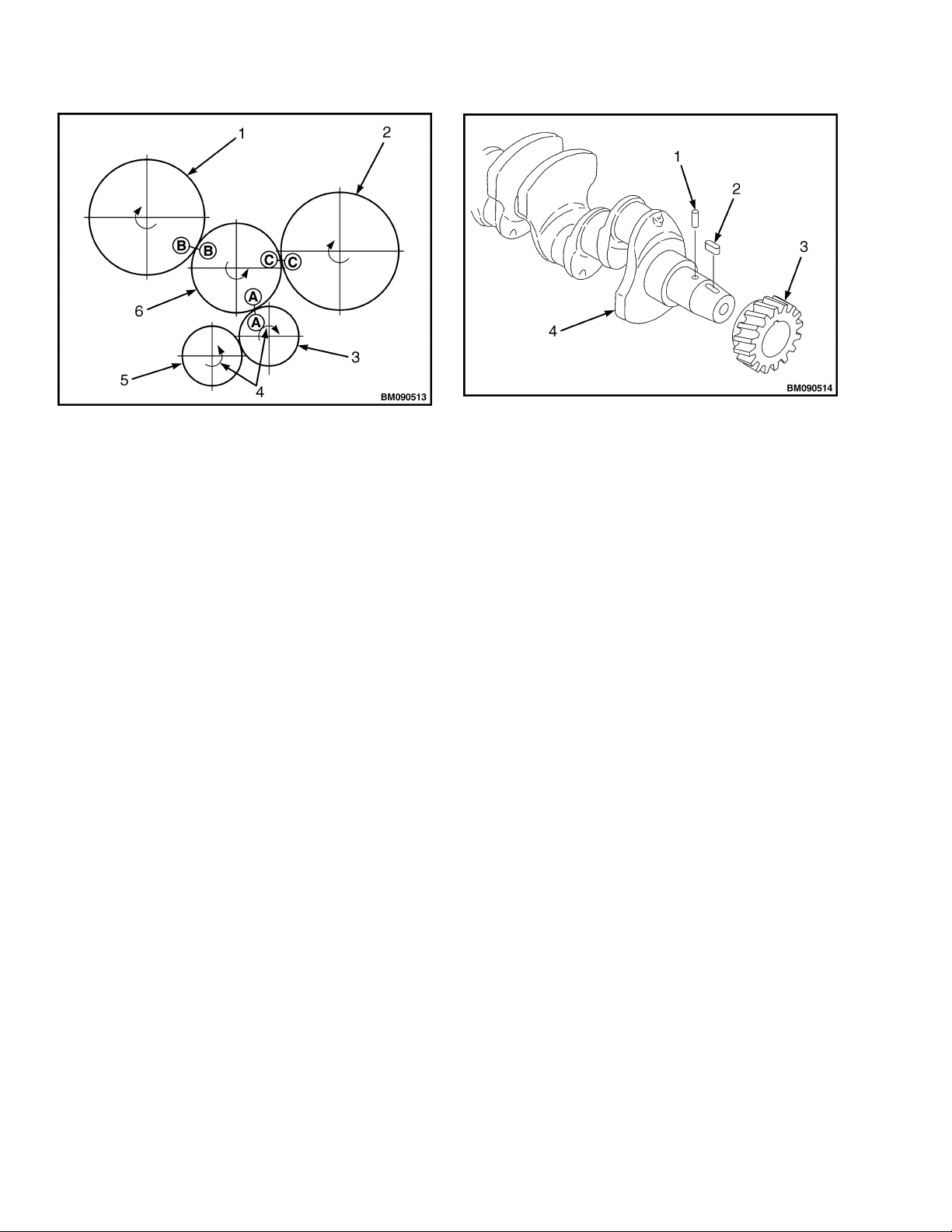
Before removing any of the timing gears, rotate the
crankshaft to align the alignment marks on the
gears as follows (see Figure 36):
Align mark "A" on the crankshaft gear with
•
mark "A" on the idler gear.
Align mark "B" on the fuel injection pump
•
gear with mark "B" on the idler gear.
Align mark "C" on the camshaft gear with
•
mark "C" on the idler gear.
23
Timing Gear Case and Timing Gears Repair 0600 SRM 1205
1. FUEL INJECTION PUMP DRIVE GEAR
2. CAMSHAFT GEAR
3. CRANKSHAFT GEAR
4. DIRECTION OF ROTATION
5. OIL PUMP GEAR
6. IDLER GEAR
Figure 36. Timing Gear Alignment
Crankshaft Gear
Remove
Remove timing gear case cover. See Timing
1.
Gear Case Cover, Remove.
Verify that the gears are properly aligned with
2.
the alignment marks. See Figure 36.
NOTE: If using a gear puller to remove the
crankshaft gear, be careful not to damage the
threads in the end of the crankshaft.
Remove the crankshaft gear. See Figure 37.
3.
Remove the parallel pin and the key from the
4.
crankshaft.
1. PARALLEL PIN
2. KEY
3. CRANKSHAFT GEAR
4. CRANKSHAFT
Figure 37. Crankshaft Gear
Install
Install the parallel pin and the key into the
1.
crankshaft.
Align the alignment mark "A" on the
2.
crankshaft gear with the alignment mark "A"
on the idler gear and install the crankshaft
gear onto the crankshaft.
Verify that all alignment marks are properly
3.
aligned. Figure 36.
Install timing gear case cover. See Timing Gear
4.
Case Cover, Install.
Idler Gear
Remove
Remove the timing gear case cover. See Timing
1.
Gear Case Cover, Remove.
24
Verify that the gears are properly aligned with
2.
the alignment marks. See Figure 36.
Remove the bolts from the idler gear shaft. See
3.
Figure 38.
Remove the idler gear shaft, idler gear, and
4.
bushing.
 Loading...