

Page 1

Installation and Reference Manual
™
SwingSmart DC
SwingSmart DC 20
SwingSmart DCS 20 (solar)
Pad-mounted, electromechanical swing gate operator with Smart DC Controller
Sales: 1-800-321-9947 Fax: 1-888-321-9946
www.hysecurity.com Email: info@hysecurity.com
Tech Support: Call your dealer or distributor
6623 South 228th Street, Kent, WA 98032
Sold by
Dealer/Installer: __________________________
Phone: ________________________________
Distributor: ______________________________
Phone: ________________________________
D0149
Page 2
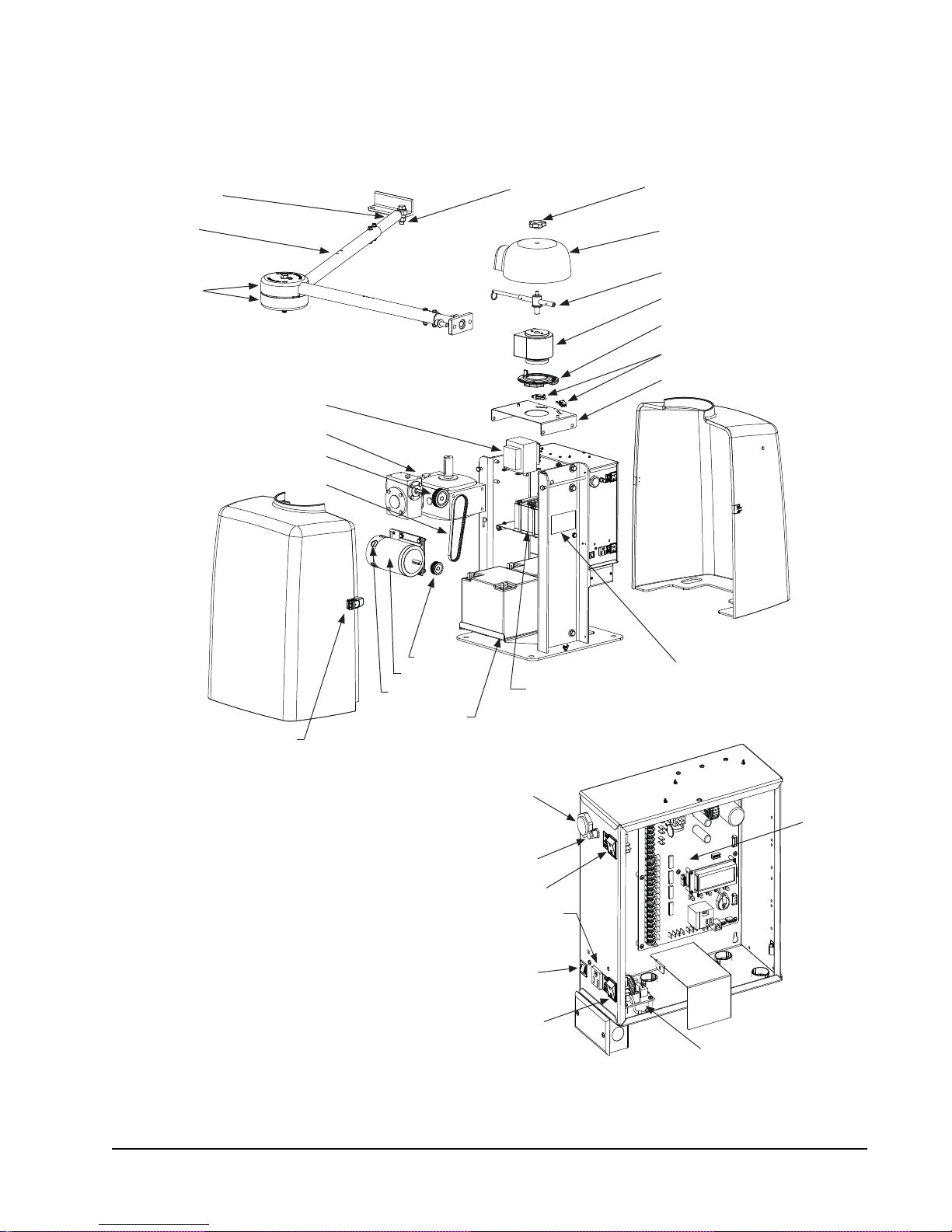
SWINGSMART COMPONENTS
A
Buzzer
Switch, Reset
DC Switch, On/Off
Circuit Breaker
Board, Power Supply
Board,
Smart DC
Controller
AC Switch, On/Off
115VAC Convenience Outlet
Stub Arm
rm Assembly
Cover, Pinch
Rear Cover
Transformer
Gearbox
Pulley, Gearbox
Belt
Swivel Eye Bolt
Knob,
Top Cap
Cover,
Top Cap
Handle, Clamp
Taper Clamp Assembly
Limit Plate with Limit Cams
Limit Switch
Bracket, Limit Switch
Front Cover
Cover Latch (2)
Pulley, Motor
DC Motor
Brush
Battery Kit, 50AH
(optional)
Label, Serial/Model #
Battery Kit, 8AH
Note: Refer to Parts & Limited Warranty for the SwingSmart parts list.
Revision A Intro-1
Page 3

PRODUCT & WARRANTY REGISTRATION
Enter the following information to register your HySecurity product. Please write legibly. Today’s Date:_____________________
NOTE: To extend the operator warranty beyond 1 year, be sure to return this registration within 60 days of purchase. Refer to the Limited Warranty.
Installer Information
First/Last Name: _________________________________________
Company Name: _________________________________________
Address: _______________________________________________
City: ____________________________ State/Province: __________
Country: _______________________ Postal Code: ____________
Daytime Phone: ___________________ Fax: __________________
E-mail: _________________________________________________
End-user Information
First/Last Name: _________________________________________
Company/Association: ____________________________________
Address: _______________________________________________
City: ____________________________ State/Province: __________
Country: _______________________ Postal Code: ____________
Daytime Phone: ___________________ Fax: __________________
Product Information
Model name/number: ______________________________________
Serial number: ___________________________________________
Purchase Date: __________________________________________
Purchase Price: __________________________________________
Distributor’s name: _______________________________________
Distributor’s City: ________________________________________
Country: ________________________________________________
Installation Date: _________________________________________
Who is completing this form?
Installer End User Distributor
Maintenance Personnel Other ___________________
Additional Comments
_______________________________________________________
E-mail: _________________________________________________
Did you visit the HySecurity website bef ore purchasing your product?
Yes No
How did you hea r about HySecurity gate operators? (Check all that apply.)
Advertisement Exhibition Distributor
Business associate Other (please specify): ____________________________________
What factor(s) most influenced your purchase? (Check all that apply.)
Performance Price Power
Reliability Brand Prior Experience
Recommendation Warranty Product Weight
Fax or Mail this completed form to:
HySecurity, Inc Fax: 888-321-9946
6623 South 228
Kent, WA 98032
HySecurity provides product installation, maintenance and troubleshooting t rai ni ng. View opportuniti es online at the HySecurity website:
www.hysecurity.com/support. For Technical Support, call 800-321-9947.
HySecurity does not share this warranty registration information with third parties unless the requested services, transactions, or legal requirements necessitate it.
© 2009 D0119 Rev. G
th
Street Email: info@hysecurity.com
_______________________________________________________
Page 4

Page 5

Contents
SwingSmart Components
Introducing SwingSmart
INTELLIGENT FEATURES: SMART DC CONTROLLERTM ......................................................................... INTRO-2
T
ECHNICAL SUPPORT .............................................................................................................................. INTRO-3
Safety Requirements
IMPORTANT SAFETY INSTRUCTIONS ............................................................................................................... S-1
Safety Standards - Installer's Responsibility ............................................................................................... S-1
Safety Standards - Owner/User Responsibility ........................................................................................... S-2
Hazardous Materials and Proper Disposal ................................................................................................. S-3
ECONDARY ENTRAPMENT PROTECTION SENSORS ........................................................................................ S-4
S
Identifying Gate Operator Category and Usage Class ................................................................................ S-5
Choosing Secondary Entrapment Protection ............................................................................................. S-6
E
MERGENCY STOP BUTTON ............................................................................................................................ S-7
C
OMMON INDUSTRIAL SYMBOLS .................................................................................................................... S-7
Chapter 1: Installation
STEP-BY-STEP ................................................................................................................................................... 1-1
P
AD CONDITION ............................................................................................................................................. 1-1
Pouring the Concrete ................................................................................................................................ 1-1
Using an Existing Pad ............................................................................................................................... 1-3
U
NPACKING THE OPERATOR ........................................................................................................................... 1-4
M
OUNTING THE OPERATOR ........................................................................................................................... 1-5
G
ATE BRACKET AND LINKAGE ARMS .............................................................................................................. 1-6
Installing the Gate Bracket ........................................................................................................................ 1-6
Attaching the Stub Arms ........................................................................................................................... 1-7
Installing the Linkage Arms ....................................................................................................................... 1-8
Adjusting the Limit Switches ................................................................................................................... 1-10
Completing Gate Arm Installation .......................................................................................................... 1-11
Setting the Taper Clamp ......................................................................................................................... 1-13
Revision A Contents - 1
Page 6

Contents
Chapter 2: Power
STEP-BY-STEP ................................................................................................................................................... 2-1
I
NSTALLING THE EARTH GROUND .................................................................................................................. 2-1
W
IRING AC POWER ......................................................................................................................................... 2-2
Wiring 115VAC Power .............................................................................................................................. 2-3
Wiring 208/230VAC Power ...................................................................................................................... 2-4
C
ONNECTING DC POWER ............................................................................................................................... 2-5
Important Considerations for DC-powered Operators ............................................................................... 2-5
Installing the Extended Battery Backup Kit ................................................................................................ 2-7
Chapter 3: Display and Menu Options
STEP-BY-STEP ................................................................................................................................................... 3-1
I
NITIAL SETUP .................................................................................................................................................. 3-1
Turning Both Power Switches On ............................................................................................................. 3-2
Using the Smart DC Controller Buttons In Menu Mode ........................................................................... 3-3
Configuring the Setup Menu ..................................................................................................................... 3-4
UN MODE ...................................................................................................................................................... 3-5
R
Understanding Gate Status Displays .......................................................................................................... 3-5
Using the Smart DC Controller Buttons In RUN Mode ........................................................................... 3-6
Viewing Operator Status Displays .............................................................................................................. 3-7
U
SER MENU ..................................................................................................................................................... 3-8
Adjusting the Close Timer ......................................................................................................................... 3-9
Setting the Time and Date ....................................................................................................................... 3-10
Setting AC Power Loss Gate Function ..................................................................................................... 3-11
Adjusting the Display Contrast ................................................................................................................ 3-12
I
NSTALLER MENU .......................................................................................................................................... 3-16
Adjusting the Gate Speed ......................................................................................................................... 3-17
Adjusting the IES Sensitivity .................................................................................................................... 3-18
Enabling the Fire Department Override ................................................................................................... 3-19
Reinstating Factory Defaults .................................................................................................................... 3-20
Chapter 4: Smart DC Controller
STEP-BY-STEP ................................................................................................................................................... 4-1
O
VERVIEW OF THE SMART DC CONTROLLER ................................................................................................. 4-2
Preliminary Testing .................................................................................................................................... 4-3
Vehicle Detector Installation Options ........................................................................................................ 4-4
Connecting HY-5A Vehicle Detectors ................................................................................................. 4-5
Installing Standard 11-Pin Box Type Vehicle Detectors ...................................................................... 4-7
Vehicle Detector Configuration and Quick Close Mode Selection ...................................................... 4-8
Contents - 2 SwingSmart - Installation, Operation and Maintenence Manual Revision A
Page 7

Contents
C
ONNECTING ACCESSORY DEVICES ............................................................................................................... 4-9
Entrapment Sensor Connections ............................................................................................................... 4-9
Access Controls ....................................................................................................................................... 4-10
Manual Push-button Station ................................................................................................................... 4-11
User Relays - Programming Procedure .................................................................................................... 4-12
Chapter 5: Bi-parting Gate Systems
STEP-BY-STEP ................................................................................................................................................... 5-1
P
OWER REQUIREMENTS .................................................................................................................................. 5-2
M
ASTER AND SLAVE WIRING CONNECTIONS ................................................................................................. 5-3
M
ASTER AND SLAVE MENU SETUP .................................................................................................................. 5-4
Chapter 6: Reference
CONNECTING A RADIO RECEIVER FOR REMOTE OPEN .................................................................................. 6-1
I
NSTALLING A MAGLOCK OR SOLENOID LOCK ............................................................................................... 6-3
Installing a Lock for 12VDC or 24VDC Systems ...................................................................................... 6-3
Installing a Lock on 24VAC Systems ......................................................................................................... 6-4
Installing a Lock for High Voltage Systems ............................................................................................... 6-4
Setting the User Relay Function in the
Installer Menu ........................................................................................................................................... 6-5
I
NSTALLING A SOLAR-POWERED OPERATOR .................................................................................................. 6-6
I
NSTALLING VEHICLE DETECTORS AND LOOPS .............................................................................................. 6-6
I
NSTALLING PHOTOELECTRIC SENSORS ........................................................................................................ 6-11
I
NSTALLING GATE EDGE SENSORS ................................................................................................................ 6-14
S
MART DC CONTROLLER TROUBLESHOOTING ............................................................................................ 6-16
Vehicle Detector and Loop Fault Diagnostics .......................................................................................... 6-23
SwingSmart Schematics ........................................................................................................................... 6-25
G
ENERAL MAINTENANCE .............................................................................................................................. 6-27
Smart Touch Analyze and Retrieve Tool ................................................................................................. 6-27
What You Need ................................................................................................................................ 6-27
Installing START Software ............................................................................................................... 6-27
Electrical Controls ................................................................................................................................... 6-28
Mechanical Maintenance ......................................................................................................................... 6-28
Drive Belt Tension and Alignment ................................................................................................... 6-29
DC Battery Replacement .................................................................................................................. 6-30
Clock Battery Replacement ............................................................................................................... 6-31
Chapter 7: Parts & Limited Warranty
SWINGSMART PARTS ...................................................................................................................................... G-1
S
WINGSMART PARTS LIST .............................................................................................................................. G-2
L
IMITED WARRANTY ...................................................................................................................................... G-3
S
WINGSMART DC SPECIFICATIONS ................................................................................................................ G-4
Revision A Contents Contents - 3
Page 8

Contents
This page intentionally blank.
Contents - 4 SwingSmart - Installation, Operation and Maintenence Manual Revision A
Page 9

Introducing SwingSmart
Thank you for purchasing our premium SwingSmart DC™ 20 swing gate operator. At HySecurity® Gate, Inc.,
we pride ourselves on quality. Our new line of electromechanical gate operators include a number of
unparalleled user benefits:
Robust - An especially strong twin channel steel chassis and adjustable taper clutch greatly improves the ability
for SwingSmart to resist damage from vehicle hits on the gate. The components on the Smart DC Controller
are protected by opto-isolators which shield them from power surges and lightning strikes.
Power - A variable speed control board supplies a powerful, continuous 24V DC motor which drives a 600:1
gearbox providing variable speeds. The electronics, motor and gear box are rated to operate in very broad
temperatures that range from -13°F to 158°F (-25°C to 70°C). SwingSmart DC is rated for gates up to 20 feet
long and 1,300 pounds.
Finesse - A variable rate of gate acceleration and deceleration, dependent upon gate weight and length, assures
very smooth handling.
UPS backup and Solar ready - Two 12V, 8 amp hour (AH) batteries will provide a fully functional gate
operator (up to 300 gate cycles) when AC power is unavailable. Four user-selectable UPS modes are available.
12VDC and 24VDC are available to power access controls. The unit’s design also incorporates space for
optional 50AH batteries to support solar applications or usage during extended power outages.
I
NTELLIGENT
Automatic adjustment and synchronization of bi-parting gates - The Smart DC Controller automatically
adjusts the gate speed to synchronize the left and right gates so that they reach the open and close positions at
the same time. Independent leaf delay adjustment for bi-parting gates is selectable in ½ second increments.
Menus and User relays - The Smart DC Controller has 48 menu items to allow installer configuration of gate
function and two user relays, which can be configured for 22 different functions.
Independent adjustment for open and close gate speeds - An easy-to-use menu on the Smart DC Controller
allows the installer to vary the open and close speed settings in a range between 10 and 15 seconds.
Intelligent Inherent Entrapment Sensor (IES) - Any impediment to gate travel is sensed by the system, stopping
gate movement per UL 325 Safety Standards. The intelligent system monitors gate power then adapts the IES
to trip at an adjustable threshold above normal power.
Improved Liquid Crystal Display (LCD) - A 32-character LCD provides increased readability for programming
and troubleshooting.
USB communications port - A direct connect provides accessibility to download system diagnostics and upload
system configurations using the Smart Touch Analyze and Retrieve Tool (START) software.
START software and diagnostics - With START software loaded on a laptop computer, you have an invaluable
management tool for all HySecurity operators. To download this free software, visit the HySecurity website at
www.hysecurity.com.
F
EATURES
: S
MART
DC C
ONTROLLER
TM
Revision A Intro-2
Page 10

Technical Support
TECHNICAL SUPPORT
For technical support, call your installer or authorized HySecurity distributor. Obtain the serial number of your
operator before calling. Refer to SwingSmart Components on the front page. For the name of a distributor near
to your locale, call HySecurity at 800-321-9947.
For information about HySecurity training for installers, maintenance personnel and end-users, refer to the
company website at www.hysecurity.com or call 800-321-9947.
Intro-3 SwingSmart - Installation, Operation and Maintenance Manual Revision A
Page 11

Safety Requirements
WARNING
!
Automatic gate operators provide user convenience and security. However, because these machines can produce
high levels of force, it is imperative that gate operator system designers, installers and end users be aware of
potential hazards associated with improperly designed, installed, or maintained systems. The gate operator is
only one component of the total gate operating system. It is the joint responsibility of the architect, site
designer, purchaser, installer and end user to verify that the total system is appropriately configured for its
intended use. Additionally, certain municipalities have established licensing, codes or regulations that regulate
automated gate system design and installation. Consult local government agencies for up-to-date rules and
regulations prior to gate system design or installation.
IMPORTANT SAFETY I NSTRUCTIONS
A moving gate can cause serious injury or death. Start the gate operator only when the gate’s
travel path is clear.
Hazards, associated with automatic gates, can be reduced with proper site design, installation, and use.
Installers, maintenance crew, and owners/users must read and follow the Important Safety Instructions in this
manual and review all the literature that accompanies the product. It is important that only qualified installer’s
handle the installation of the SwingSmart gate operator.
• A minimum of three years experience installing similar equipment.
• Proof of attending a HySecurity Technical Training seminar within the past three years.
• Significant manufacturer endorsements of technical aptitude in gate operator installati
A “qualified” installer has one of the following:
on and operation.
Underwriter Laboratories (UL) and the American Society for Testing and Materials (ASTM) are
current safety standards and regulations regarding gate operators and automated gates. To pass UL certification,
all aspects of gate installation must comply with the UL 325 Safety Standard. For the most up-to-date UL 325
Safety Standard, refer to the UL website www.ul.com. For ASTM F2200 Gate and Fence Standards, refer to
www.astm.org.
responsible for
Safety Standards - Installer's Responsibility
• Study the entire contents of this manual prior to installing, operating, or maintaining the SwingSmart gate
operator. Taking extra time to align the gate operator and verify a fully functional installation will reduce
maintenance, guarantee longest system life, and ensure customer satisfaction.
• Verify the gate operator usage class for the site. Refer to Identifying Gate Operator Category and Usage Class
for gate classifications. Install SwingSmart only when the gate operator class is correct for the site and type
of gate.
• Install an automatic operator only on gates that comply with ASTM F2200 Gate and Fence Standards.
Screen or
Revision A S-1
enclose openings in the gate per UL 325 Safety Standards.
Page 12

Important Safety Instructions
NOTE
WARNING
!
• Before attaching the operator’s arm, swing the gate in both directions. Make sure it is level and moves
freely. A gate that swings easily reduces strain on operator components. Gravity should play no part in the
opening or closing of the gate.
• Make sure there is a separate walk-through entrance nearby. Make cer
designated and signs direct pedestrians to the walk-through gate. The automated gate entry is for vehicle
use only.
• Install the gate operator on the secure (non-public) side of the gate. Swin
public areas.
• Mount access control devices beyond reach of the gate. The
→ Located in a clear line of sight to the gate.
→ Mounted
operating the controls. People attempting to access the controls by reaching through or around the
gate can be seriously injured or killed by the moving gate.
→ Incorporate a security feature to prevent unauthorized use.
• The gate operator must be properly grounded and the incoming powe
label on the junction box.
• Install enough external entrapment protection sensors so that pedestrians are protected from entrapment in
both dire
Secondary Entrapment Protection Sensors.
• Install the supplied WARNING signs on the inside and outside of the gate so they are clearly visible from
both sides of t
• Locate controls (Open, Close, Stop/Reset) where a user will have a clear view of the gate. Refer to the
Emergency Stop Button. Connect radio and other remote access (non-resetting controls) to the REMOTE
OPEN terminal.
• Open and close the gate to confirm that it was properly installed and to ensure reduced risk of entrapment.
erify the clearance between the gate and adjacent
V
• When you complete the installation, show the end-user how to:
→ Remove the operator cover.
→ Turn the power on and off.
→ Manually release the gate.
beyond 6 feet of the gate, to prevent users from touching or accessing the gate while
ctions of the gate travel and all hazard areas are fully protected. Review the information found in
he gate. Installing the signs is a requirement for UL 325 compliance.
structures per UL 325 Safety Standards.
control device
tain a clear pedestrian path is
g-type gates cannot open into
s that operate the gate must be:
r voltage must match the voltage
Gate operator instructions must be given to the owner per UL 325 Safety Standards.
Safety Standards - Owner/User Responsibility
A moving gate can cause serious injury or death. Automatic gate operators move gates with high
force. Make sure gates and gate operators are installed to reduce the risks of entrapment. Verify
your gate and gate operator comply with UL 325 Safety Standards and ASTM F2200 Gate and
Fence Standards. Ask for a copy of the gate operator’s product literature and review it. You are
responsible for educating all gate system users about proper use of the automated gate system.
S-2 SwingSmart - Installation, Operation and Maintenance Manual Revision A
Page 13

Important Safety Instructions
CAUTION
CAUTION
!
• Automatic gates are for vehicular use only; provide and maintain walkways and signs to direct pedestrians
to a separate walk-through entrance.
• An automatic gate can start at any time without warning; always keep people away from the gate area.
• Never allow children to use or play with gate controls. K
transmitters, away from children. Do not allow children to play on or around the gate or gate operator.
• Learn how to turn the power on and off. Learn how to manually release the gate.
Before attempting a manual release, make sure the gate is not moving.
• WARNING signs supplied with the gate operator must remain installed and clearly visible on both sides of
the gate. The signs are required to maintain UL 325 compliance.
• Do not physically disable the warning buzzer and NEVER disconnect or cut its wires. The buzzer is
equired to function in the event of entrapment, regardless of UL 325 gate usage class. It provides an alert
r
that the gate is about to move. Disabling the warning buzzer may increase the risk or extent of injury if
entrapment occurs.
• Test the primary Inherent Entrapment Sensor (IES) and secondar
monthly. The gate must r
senses a second activation signal in a row, before it reaches its full travel limit.
• Have a professional gate installer routinely test the entir
Repair gate hard
operator on a regularly maintained schedule can increase the risk of injury or death.
ware as necessary to keep the gate running smoothly. Failure to adjust and test the gate
everse its direction of travel upon contact with a rigid object and/or stop, when it
eep all re
e gate operator and entrapment protection sensors.
mote controls, especially radio
y entrapment protection sensors
Hazardous Materials and Proper Disposal
SwingSmart uses sealed, state-of-the-art Absorbed Glass Mat (AGM) batteries and highly recommends
replacing used batteries with new AGM-type batteries.
The batteries used with the SwingSmart gate operator contain materials that are considered hazardous to the environment. Proper disposal of the battery is required by federal law. Refer to
federal guidelines found in Hazardous Waste Regulations.
To reduce the risk of fire or injury to persons:
• Observe the polarity between the batteries and charging circuit.
Never mix battery sizes, types, or brands. HySecurity strongly recommends that only sealed AGM style
•
batteries be used.
• Exercise care in handling batteries. Be aware that the metal found in rings, bracelets, and keys can conduct
electricity, short the batteries, and cause potential injury.
• Do not open or mutilate the batteries. Battery cells contain corrosive materials which may
other injuries. The material within batteries is toxic.
• Always dispose of batteries properly. Do
federal guidelines for proper disposal of hazardous waste.
• R
eplace batteries according to the instructions found in General Maintenance.
NOT place batteries in fire. The battery cells may explode. Follow
cause burns and
S-3 SwingSmart - Installation, Operation and Maintenance Manual Revision A
Page 14

Secondary Entrapment Protection Sensors
CAUTION
!
S
ECONDARY
SwingSmart is equipped with a primary, Type A, inherent entrapment sensor (IES). UL 325 Safety Standard
compliance requires installation of secondary entrapment protection sensors, the number of which, depends on
the entrapment hazards that exist at each particular installation.
To comply with UL 325, the following external sensors may be used:
• Contact sensors, such as edge sensors
• Non-contact sensors, such as photoelectric eyes
The site designer or installer can choose either photoelectric eyes or edge sensors or use these devices in
combination. Whatever devices are used, protection in both the opening and closing directions of gate travel
must be provided.
The UL 325 Safety Standard for automatic swinging gates specifically requires that edge sensors or
photoelectric eyes or a combination of both devices be installed to protect against pedestrian entrapment in
BOTH directions of the gate travel and where an entrapment hazard exists.
PHOTOELECTRIC EYES: One or more photoelectric eyes shall be located where the risk of entrapment or
obstruction exists, such as the perimeter reachable by a moving gate.
E
NTRAPMENT
P
ROTECTION
S
ENSORS
A photoelectric eye or contact sensor is also required to protect against possible entrapment if
the gate opens to a position less than 16 inches from any object, such as a post or wall.
EDGE SENSORS: One or more edge sensors shall be located on the inner and outer leading edge of a swing
gate where the risk of entrapment or obstruction exists. If the bottom edge of the swing gate is situated more
than 6-inches (152 mm) above ground level at any point in its arc of travel, one or more contact sensors must
be located on the bottom edge, as well.
SENSOR SECURITY: A hard-wired sensor shall be located and its wiring arranged so that communication
between the sensor and gate is not subjected to mechanical damage.
SENSOR FUNCTION and COMMUNICATION: A sensor that transmits its signal to the gate operator
must be located so its signal is not impeded by building structures or other obstructions. All sensors must be
installed so that they function as intended for the end-use conditions.
UL 325 LISTING: The edge sensors and photo electric eyes must be tested and labeled as “Recognized
Components” under UL 325 in order to be deemed acceptable for use in a gate operator. Study the Important
Safety Instructions and consider your specific installation to determine where the greatest entrapment risks exist.
Locate edge sensors and/or photoelectric sensors accordingly.
Be certain that a sufficient number of sensors are used so that pedestrians are protected from entrapment in
both directions of the gate travel and all hazard areas are fully protected. Refer to the UL website at
www.ul.com for the most up-to-date list of gate operator safety standards (UL 325). Refer to www.astm.org for
a complete list of ASTM F2200 Gate and Fence Standards.
S-4 SwingSmart - Installation, Operation and Maintenance Manual Revision A
Page 15
Secondary Entrapment Protection Sensors
Identifying Gate Operator Category and Usage Class
The SwingSmart operator, according to UL 325 Safety Standards, falls in the Swing Gate and Vertical Barrier
Arm category for gate operators. It’s usage class is determined by the area that the vehicular gate services.
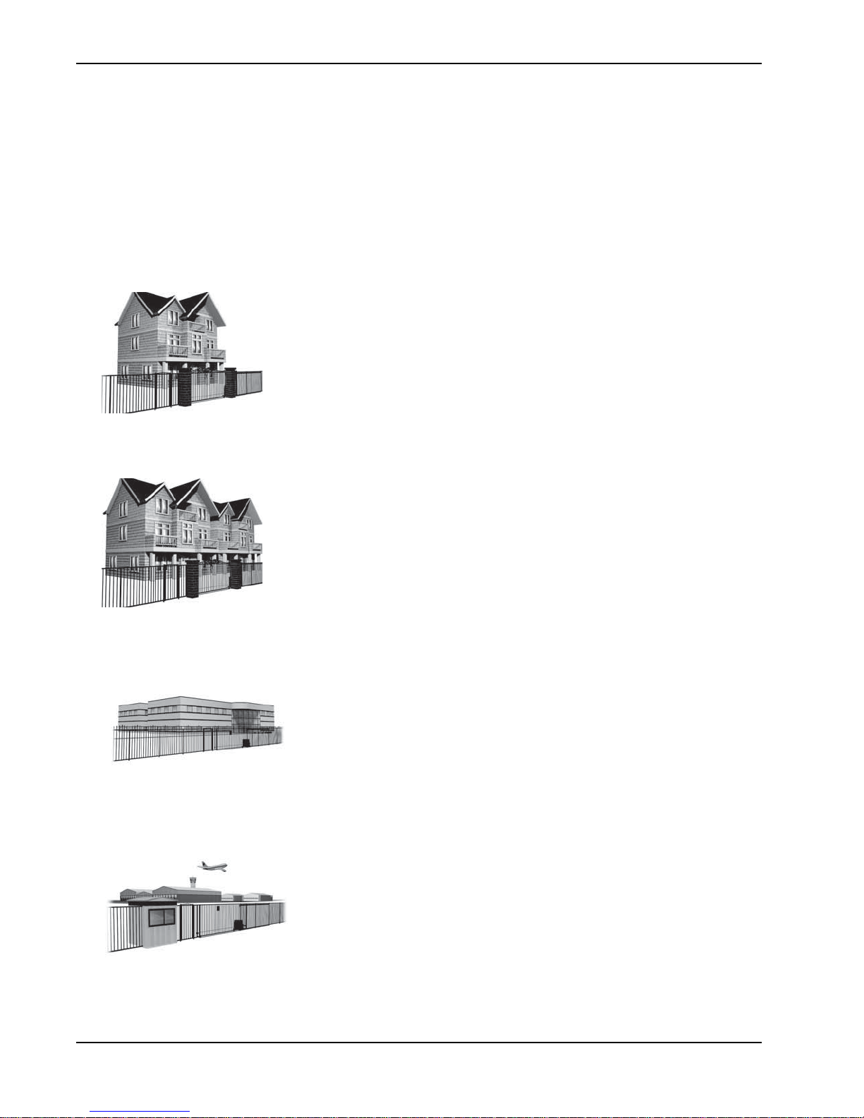
Four different vehicular usage classes are defined by UL 325:
Class I
Class I: Intended for use in a location of one to four single family dwellings or a
parking area associated with one to four single family dwellings.
Class II
Class III
Class IV
Class II: Intended for use in a commercial location or building such as a multifamily housing units (five or more single family units) hotels, garages, retail stores
or other buildings servicing the general public.
Class III: Intended for use in an industrial location or building such as
factories or loading docks or other locations not intended to service the
general public.
Class IV: Intended for use in guarded industrial locations or buildings such
as an airport security area or other restricted access location, not servicing
the general public, in which access is monitored by security personnel or via
closed circuitry.
S-5 SwingSmart - Installation, Operation and Maintenance Manual Revision A
Page 16
Secondary Entrapment Protection Sensors
NOTE
CAUTION
Choosing Secondary Entrapment Protection
The site designer or installer must determine which secondary entrapment sensor devices will be installed with
the SwingSmart operator to meet UL compliance. The type of entrapment sensor device systems are described
below. For a complete listing of the requirements, see UL 325 Safety Standards.
SwingSmart is equipped with a primary, Type A, inherent entrapment sensor (IES) that complies with UL 325. Any impediment to gate travel causes the gate to stop.
Usage Class Primary Type Device Secondary Type Device
Class I, II, III A B1, B2, C, or D
Class IV A B1, B2, C, D, or E
To comply with UL 325, refer to the chart and take the following steps:
1. Select the Usage Class according to the gate’s locale and purpose.
2. The required UL 325 primary Type A sensor is an integral part of the
3. Based on the gate’s usage class, choose Secondary Type
• To comply using B1 - install non-contact sensors (photoelectric sensor or the equivalent).
• To comply using B2 - install contact sensors (edge sensor device or the equivalent).
• To comply using a Type D device requires a CONSTANT HOLD push-button station. This CONSTANT
HOLD push-button station must be the only device that opens and closes the gate. It can only be used where
the gate and push button station will be monitored by personnel 24 hours a day in full view of the gate area.
An automatic closing device (such as a timer, loop sensor, or similar device) must not be employed. A Warning
placard stating, “WARNING - Moving Gate has the Potential of Inflicting Injury or Death - Do Not Start the
Gate Unless the Path is Clear” must be placed adjacent to the gate operator controls.
While compliance is possible with Type C, which is a low force limiting clutch, the SwingSmart
operator develops more gate actuation force than is permitted under the UL 325 Safety Standards and, therefore, its clutch cannot be considered an entrapment protection device.
Similar compliance issues exist with a Type E device (audio warn before operate alarm). A Type
E device is permitted as a means of secondary entrapment protection by UL 325 in Class IV
applications, but it is not recommended by HySecurity because a buzzer warns, but cannot
protect against possible entrapment. HySecurity highly recommends, even for Class IV use, that
secondary entrapment protection (edge or photo-eye sensor) devices be installed to detect
possible entrapment.
Devices: B1, B2, C, D, or E.
SwingSmart system.
S-6 SwingSmart - Installation, Operation and Maintenance Manual Revision A
Page 17
Emergency Stop Button
Emergency
Stop button
Attention
- Take Note -
- Danger -
Keep Away
Entrapment
Zone
Possible
Pinch Point
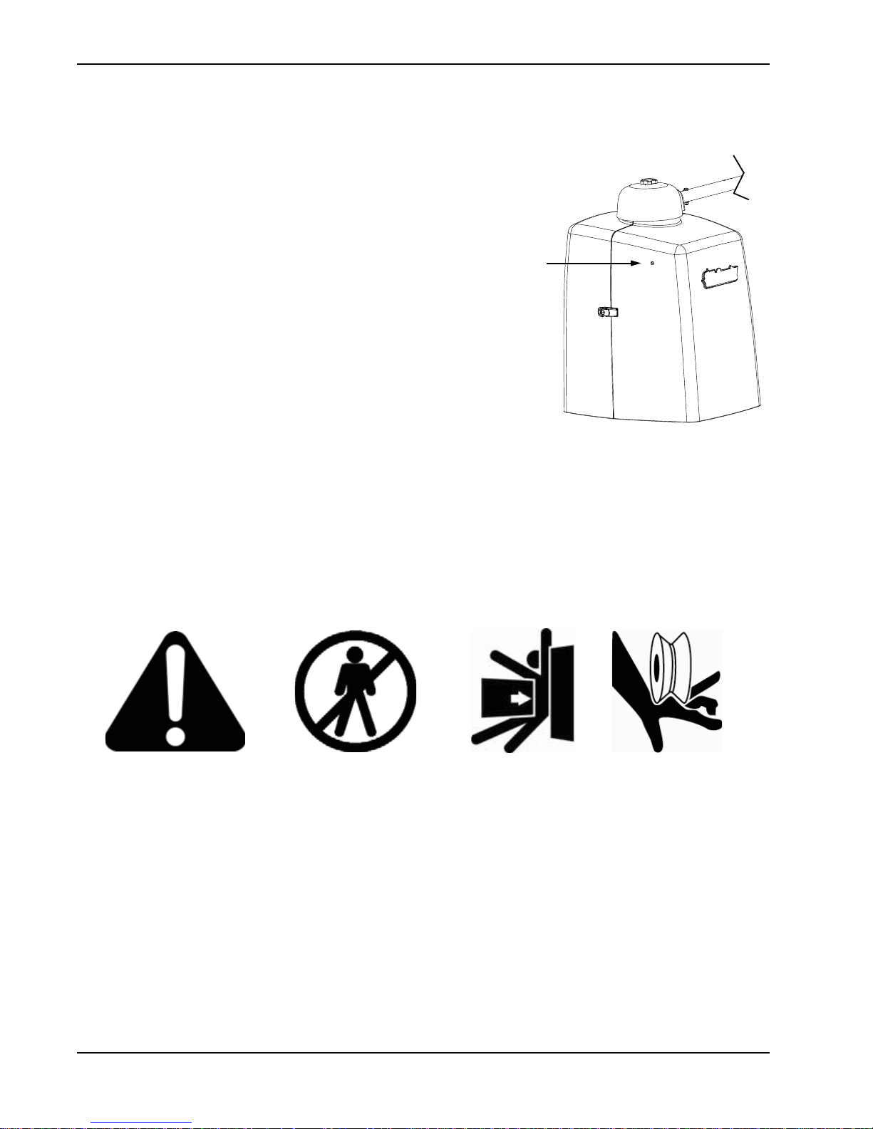
EMERGENCY STOP BUTTON
An emergency stop button that is accessible from the
outside of the operator is a requirement for compliance
with UL325 Safety Standards. The red emergency stop
button on the SwingSmart operator is located inside a hole
cutout on the cover.
Pressing the emergency stop button while the gate is
opening or closing disables the automatic close timer and
stops gate travel. The gate travel remains stopped until the
operator receives any open or close signal.
Make sure all users of the gate know where the emergency
stop button is located.
A screwdriver or hex key can be used to press lightly on the
switch to activate it.
COMMON INDUSTRIAL SYMBOLS
The following international safety symbols may appear on the product or in its literature. The symbols are used
to alert you to potential personal injury hazards. Obey all safety messages that follow these symbols to avoid
possible injury or death.
S-7 SwingSmart - Installation, Operation and Maintenance Manual Revision A
Page 18

Common Industrial Symbols
This page intentionally blank.
S-8 SwingSmart - Installation, Operation and Maintenance Manual Revision A
Page 19
Installation
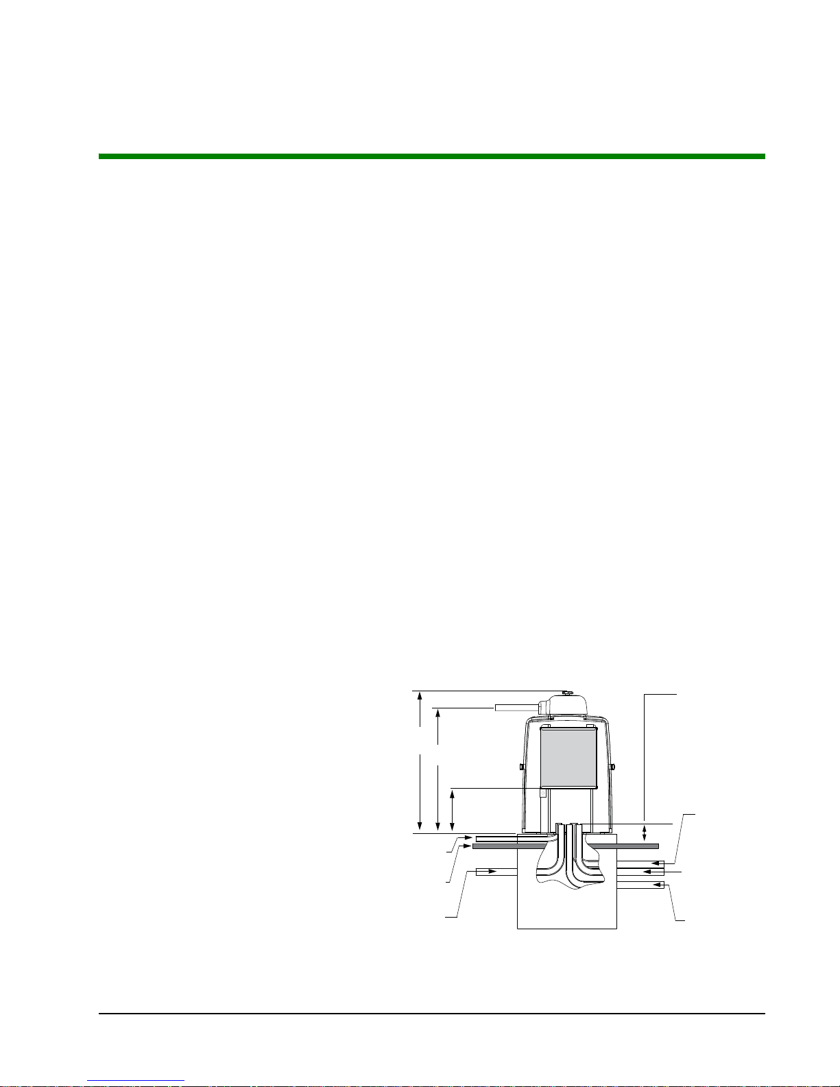
Figure 1-1.
Low voltage/
Communication
wires
Master/slave
wires - optional
High voltage
30.2”
26.8”
Vehicle Loop
control wires
Earth ground
Ground level
9.6-inch
control box
height
Stub out conduit
4-inches above
ground level
(2-inch height
above pad.
TEP-BY-STEP
S
1. Pour pad and mount SwingSmart - Chapter 1.
2. Install gate bracket & linkage arms - Chapter 1.
3. Adjust open and close limit switches - Chapter 1.
4. Connect power - Chapter 2.
5. Program the Initial Setup Menu on the Smart DC Controller - Chapter 3.
6. Configure the User and Installer Menu options - Chapter 3.
7. Review the connections on the Smart DC Controller - Chapter 4.
8. Install Master/Slave connections - Chapter 5.
9. Attach accessory devices - Chapter 6.
Chapter 1
PAD CONDITION
Pouring the Concrete
1. Follow the local building codes to
identify the frost line and determine
the required depth of the concrete pad.
HySecurity recommends a minimum
16-inch depth with a minimum 2-inch
extension above ground level. Refer to
and Figure 1-2.
supply po
equipment ground
accessory power)
• veh
• master/slave connections
wer) including
icle loop control wiring
Figure 1-1
2. Before pouring the pad, consider
conduit placement so it fits within the
confines of the cutout in the
Sw
ingSmart base plate as shown in
Figure 1-2. Run separate conduits for:
•high voltage wiring (115-230V
• low voltage wiring (12V and 24V
•earth ground (NEC/NFPA)
Revision A 1-1
Page 20
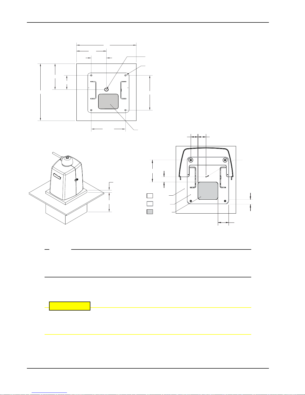
10.5"
10.5"
23"
21"
12"
14"
5.3"
5.7"
Output Shaft Center
Drill 4 holes for ½" x 3 ½" concrete anchors
6" x 7" conduit area
Pad Condition
NOTE
CAUTION
2.5 "
2.8"
7.6"
2
-inch m
inimum
1.8"
COVER AREA
Pad Depth: 16-inch minimum
CHASSIS BASE
CONDUIT AREA
6 " x 7 "
Figure 1-2.
3.5"
SwingSmart provides a 6-inch by 7-inch cutout in its chassis base for conduit.
Refer to Figure 1-2. The design also provides a 9.6-inch height between the control box and
chassis base for pulling and placement of wires.
Output Sha Center
1.5"
3. Extend conduit height 2-inches above the pad (4-inches above ground level). Make sure the concrete forms
are square with the gate and the pad is level. Refer to Figure 1-2 for minimum pad dimensions.
Be sure to restrict conduit to the 6-inch by 7-inch cutout in the chassis base if you plan to use
the extended battery backup kit. The area designed for the optional dual 50AH batteries may be
obstructed if conduit is routed elsewhere. Refer to Installing the Extended Battery Backup Kit.
1-2 SwingSmart - Installation, Operation and Maintenance Manual Revision A
Page 21

Pad Condition
CAUTION
Using an Existing Pad
In many applications, SwingSmart may be a replacement operator for an existing gate system. Make sure the
pad is level and inspect the pad for:
• Compliance with local building codes.
• Appropriate distance from the gate. Refer to Figure 1-2.
• Appropriate dimensions for SwingSmart installation.
• Durability.
To use an existing pad, take the following steps:
1. Remove any existing equipment from the pad.
2. Measure the pad to ensure it is sized properly for SwingSmart.
3. Mark the center shaft location.
4. Follow the steps in Mounting the Operator.
Consider positioning the operator so existing conduit exits through the cutout in the SwingSmart base plate. Cutting small holes in the base plate for pre-existing conduit is permissible,
but not recommended because it can impair the strength of the chassis and void the Limited
Warranty.
Revision A Installation 1-3
Page 22
Unpacking the Operator
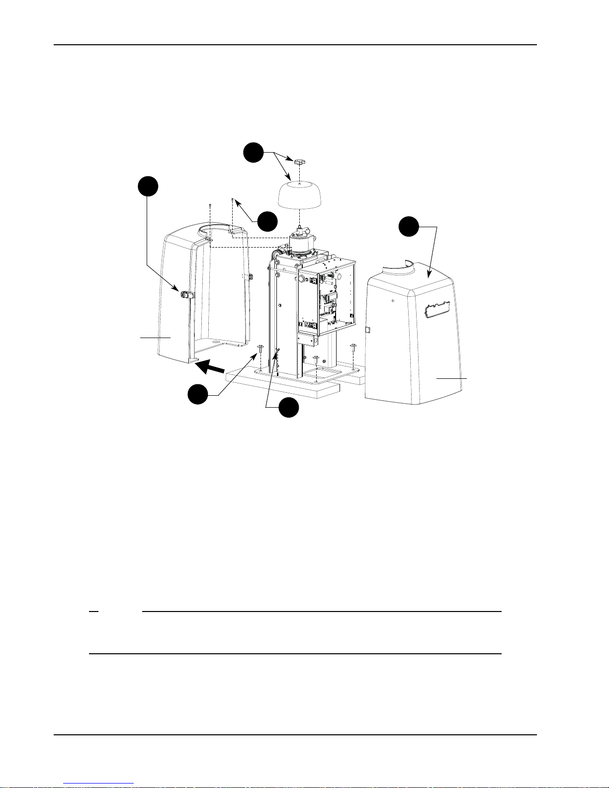
1
2
3
5
6
4
Front cover
Rear cover
NOTE
UNPACKING THE OPERATOR
1-4 SwingSmart - Installation, Operation and Maintenance Manual Revision A
Figure 1-3.
Prepare the gate operator for installation. See Fig
1. Remove the top cap by unscrewing the knob.
2. Unfasten the side cover latches.
3. Remove the front cover.
4. Use a Phillips-head screwdriver to remove the two screws that secure the top of the rear cover. Set the
screws aside.
5. Remo
6. Remove the four wood screws and separate the operator from the shipping boards.
ve the two wing nuts that secure the rear cover to the base plat
wing nuts aside.
Do not lose the Phillips-head screws or wing nuts as they are used to secure the rear cover when
the installation is complete.
ure 1-3.
e and set the rear cover aside. Set the
Page 23
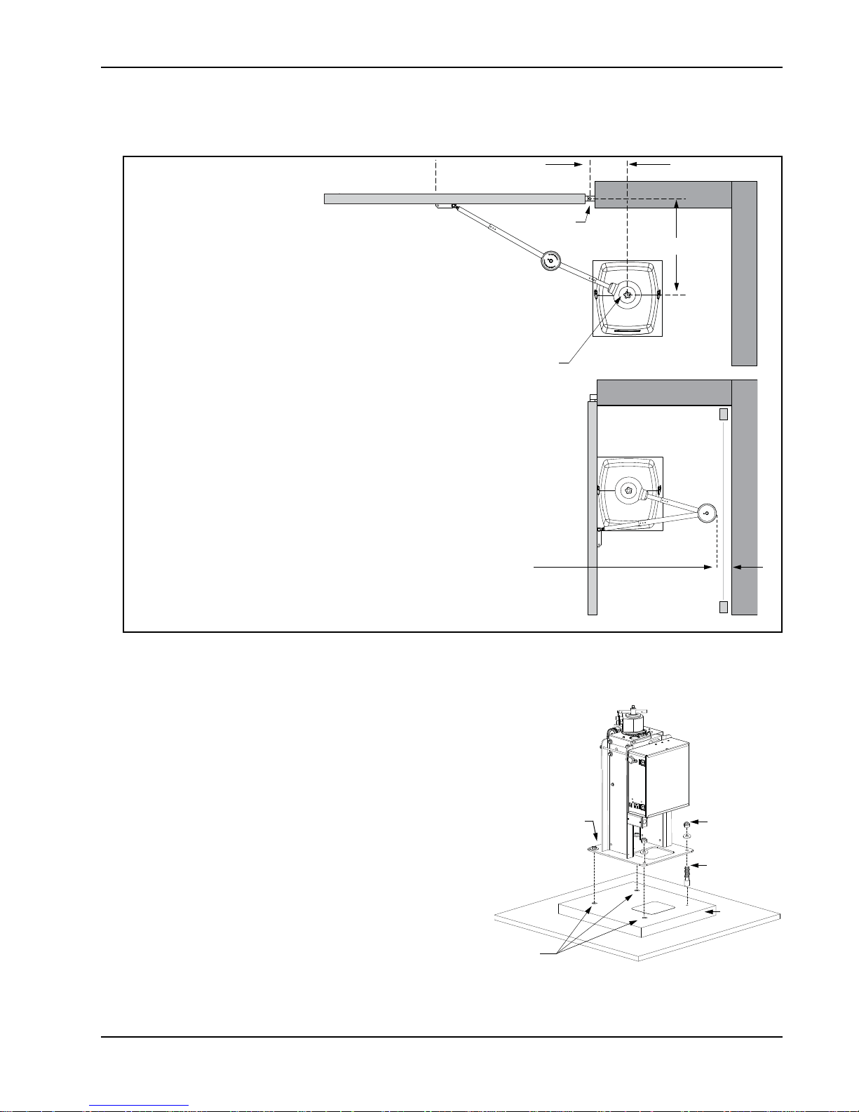
MOUNTING THE OPERATOR
Photo Eye
Photo Eye
For short gates up to 10 feet:
If X = 10.5 inches then set the Y
dimension at 14, 18, or 20 inches.
For medium gates up to 13 feet:
If X = 12 inches, then set the Y
dimension at 22, 24, or 28 inches.
For long gates up to 20 feet:
If X = 15 inches, then set the Y
dimension at 30, 35, or 40 inches.
Hinge Center
Output Shaft Center
X
Y
Potential entrapment area.
Minimum 16-inch clearance required.
If less than 16-inches, install a photoeye or edge sensor.
Figure 1-5.
Concrete
anchor
Fasteners
Concrete
anchors
Base plate
Concrete
pad
Mounting the Operator
Install the operator, by taking the following steps:
1. Assess any limitations in the surrounding area such as
curbs, walls, or bushes.
2. Before placing the operator on the pad, measure and
mark the output shaft center on the concrete pad by
selecting the X and Y dimensions. Refer to Figure 1-2
and Figure 1-4.
3. Set the operator base on the concrete pad and use it as a
ate. Position the operator base so the ce
templ
on the pad aligns with the small hole in the base plate.
Mark the fastener and conduit cutouts. Remove the
operator from the concrete pad and drill the holes for
the concrete anchors.
4. Mount the operator with four ½ x 3½-inch concrete
anchors as sho
Revision A Installation 1-5
wn in Figure 1-5
Figure 1-4.
.
nter mark
Page 24

Gate Bracket and Linkage Arms
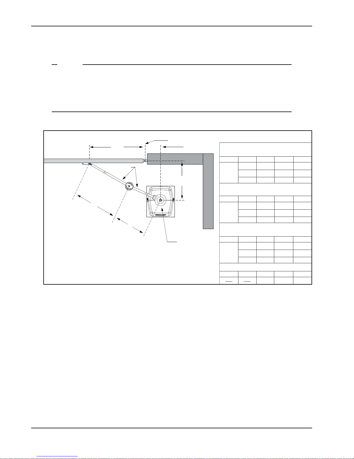
Short Gate Installation:
For gates up to 10 feet
X
Y
Xg
14 23.5
10.5
18 27.5
20 29.5
X
Y
Xg
22 33.0
12
24 35.0
28 39.0
Medium Gate Installation:
For gates up to 13 feet
X
Y
Xg
30 44.0
15
35 49.0
40 54.0
Long Gate Installation:
For gates up to 20 feet
Custom Gate Installation:
X
Y
Xg
X + Y - 1
Operator Center
Photo eye
Horizontal
cross member
Hinge Center
X
Y
Xg
Gate operator - shows left arm
mounted on right-hand gate.
CAUTION
!
GATE BRACKET AND LINKAGE ARMS
Installing the Gate Bracket
1. Secure the gate to prevent movement.
If vertical bars make up the gate design, be sure to install a horizontal cross member to provide
the necessary support to the gate arm. Do not mount the bracket to a small number of vertical
pickets. Pickets will bend in the event of a gate strike.
1-6 SwingSmart - Installation, Operation and Maintenance Manual Revision A
2. Determine the proper position of the gate bracket. Use the chart for reference.
Hint: Determine if you have a short, medium, or long gate. If the X and Y dimensions in
same as your install, set the gate bracket at the Xg dimension. If your install does not fit to the chart specs,
use the Custom Gate Installation formula to determine the proper gate bracket placement.
3. Measure and position the gate bracket so it is level with the arm on the operator. Clamp the gate bracket to
the horiz
ontal cross member.
Figure 1-6.
the chart are the
Page 25
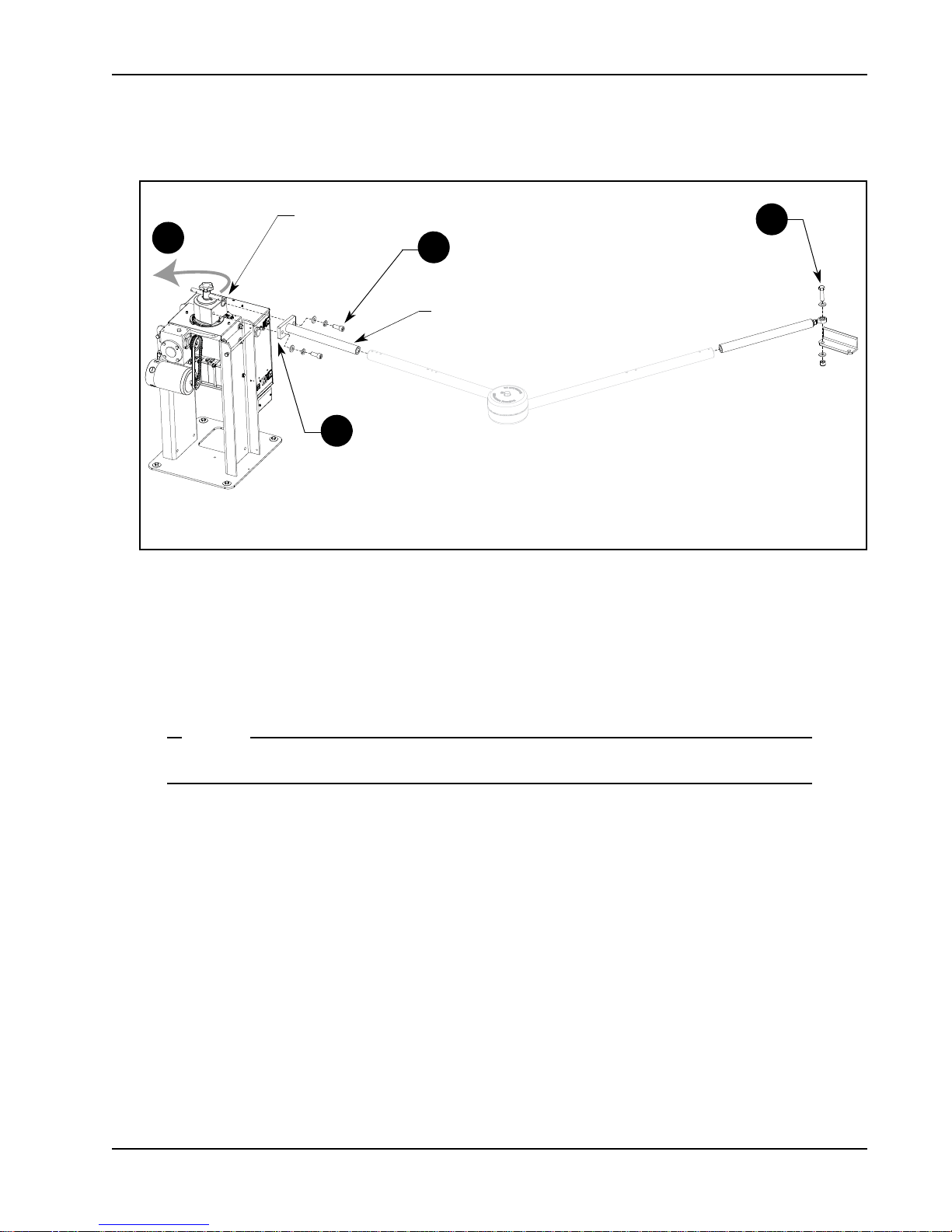
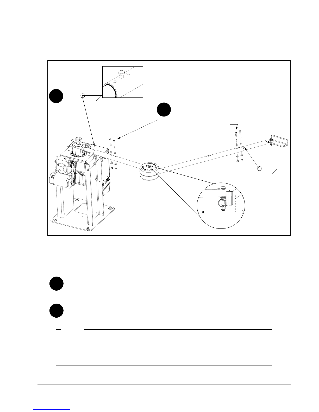
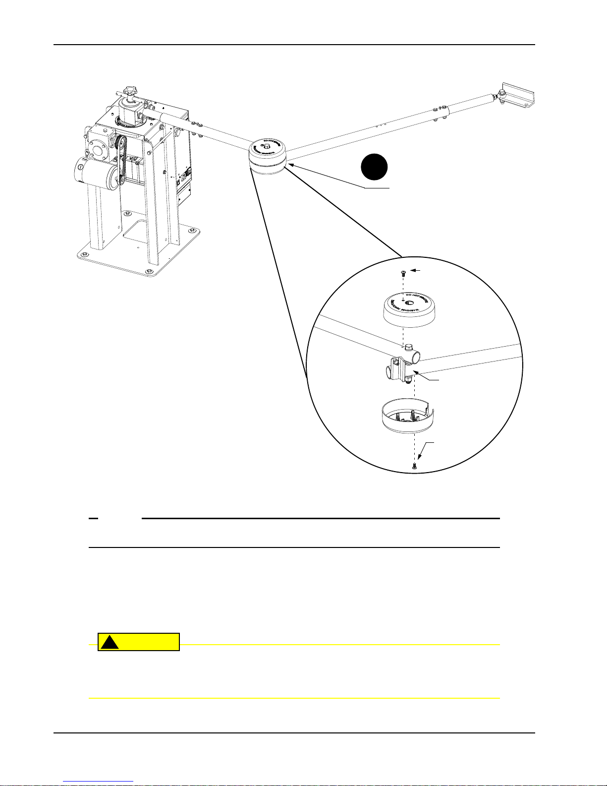
Attaching the Stub Arms
2
1
4
3
Taper handle
Stub arm
NOTE
Gate Bracket and Linkage Arms
Figure 1-7.
1. Attach the swivel eye bolt to the gate bracket using the fasteners provided.
2. Remove the fasteners from the taper clamp assembly.
3. Align the stub arm and secure it to the taper clamp assembly
4. Pull the taper handle to lengthen it. Adjust the handle so the ball detent fits into its cutout and secures the
handle length. Turn the hand
Do not retighten the taper clamp. It needs to remain loose for manual gate adjustments.
le counter clockwise to loosen the taper clamp. Figure 1-7.
using the fasteners remov
ed in step 2.
Revision A Installation 1-7
Page 26
Gate Bracket and Linkage Arms
Short Gate Installation:
For gates up to 10 feet
X
Y
Xg
14 23.5
10.5
18 27.5
20 29.5
X
Y
Xg
22 33.0
12
24 35.0
28 39.0
Medium Gate Installation:
For gates up to 13 feet
X
Y
Xg
30 44.0
15
35 49.0
40 54.0
Long Gate Installation:
For gates up to 20 feet
Custom Gate Installation:
X
Y
Xg
X + Y - 1
A
B
15.5 21.5
17.5 24.5
19.0 26.0
A
B
21.0 29.0
22.0 30.5
24.5 33.5
A
B
28.0 38.5
30.5 42.5
33.5 46.5
A
B
0.87 * Xg
0.63 * Xg
X
Xg
Hinge Center
Y
Operator Center
A
B
Linkage arms
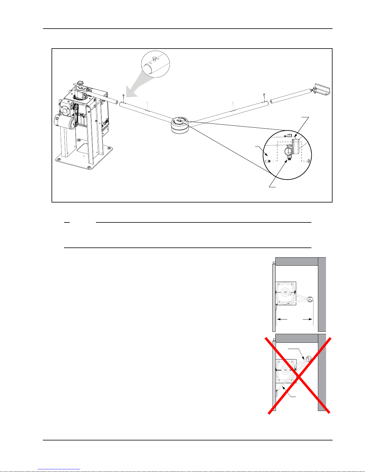
NOTE
Installing the Linkage Arms
SwingSmart operators ship with a standard left-hand linkage arm. The left-hand linkage arm
can be used on a right-hand operator (and vice versa) by flipping the arm. This causes the gate
attachment point to be approximately 2-inches higher which means the gate bracket needs to be
positioned accordingly. For aesthetics and ease of installation, order a left-hand and right-hand
arm for bi-parting gate systems.
1. Slide the linkage tubes on the appropriate stub arms and use the tapped holes for adjust
Tighten the hex-head bolts to hold the arms in place. Refer to Figure 1-9.
2. Verify the A and B dimensions on the arm linkage tubes. For short gate applications, the linkage arms must
1-8 SwingSmart - Installation, Operation and Maintenance Manual Revision A
be cut
use the Custom Gate Installation formula to determine the proper length.
to achieve the required lengths. See Figure 1-8. If your operator position does not fit the chart specs,
Figure 1-8.
ment purposes.
Page 27
Note: Elbow pivot bolts must be parallel with the vertical axis of the operator . If the pivot bolt is
not vertical, binding of the arm assembly may occur during operation.
Elbow
Pivot bolt runs parallel
with the vertical axis of
the operator.
Tapped hole used for
linkage arm adjustments.
Set screw
Gate Bracket and Linkage Arms
NOTE
Figure 1-10.
CORRECT
alignment with
gate in the open
position.
INCORRECT
alignment.
Linkage arm (B)
needs to be
shortened.
B
A
B + 3
Figure 1-9.
The linkage tubes used for the arm can be drilled and bolted or welded together. Do the finishing
work AFTER the arm and gate adjustments are complete. See
Completing Gate Arm Installation
3. To verify appropriate arm length, manually push the gate to the
full open and close positions. Maximum security is obtained
when the elbow on the linkage arms is slightly bent with the gate
closed and at an approximate 90° angle with the gate in the open
position. See Figure 1-10
. Refer to NOTE on page 1-11.
4. During the open and close process:
• Verify all pivot joints rotate smoothly without binding. At
the full open position, linkage arms must
bind.
not scissor or
• Make sure the longer arm (B) does not collide with the top
cap cover.
•See
Figure 1-9 and make adjustments to arm lengths by:
• loosening the set screws
• telescoping the arms
• retightening the set screws
.
Revision A Installation 1-9
Page 28
Gate Bracket and Linkage Arms
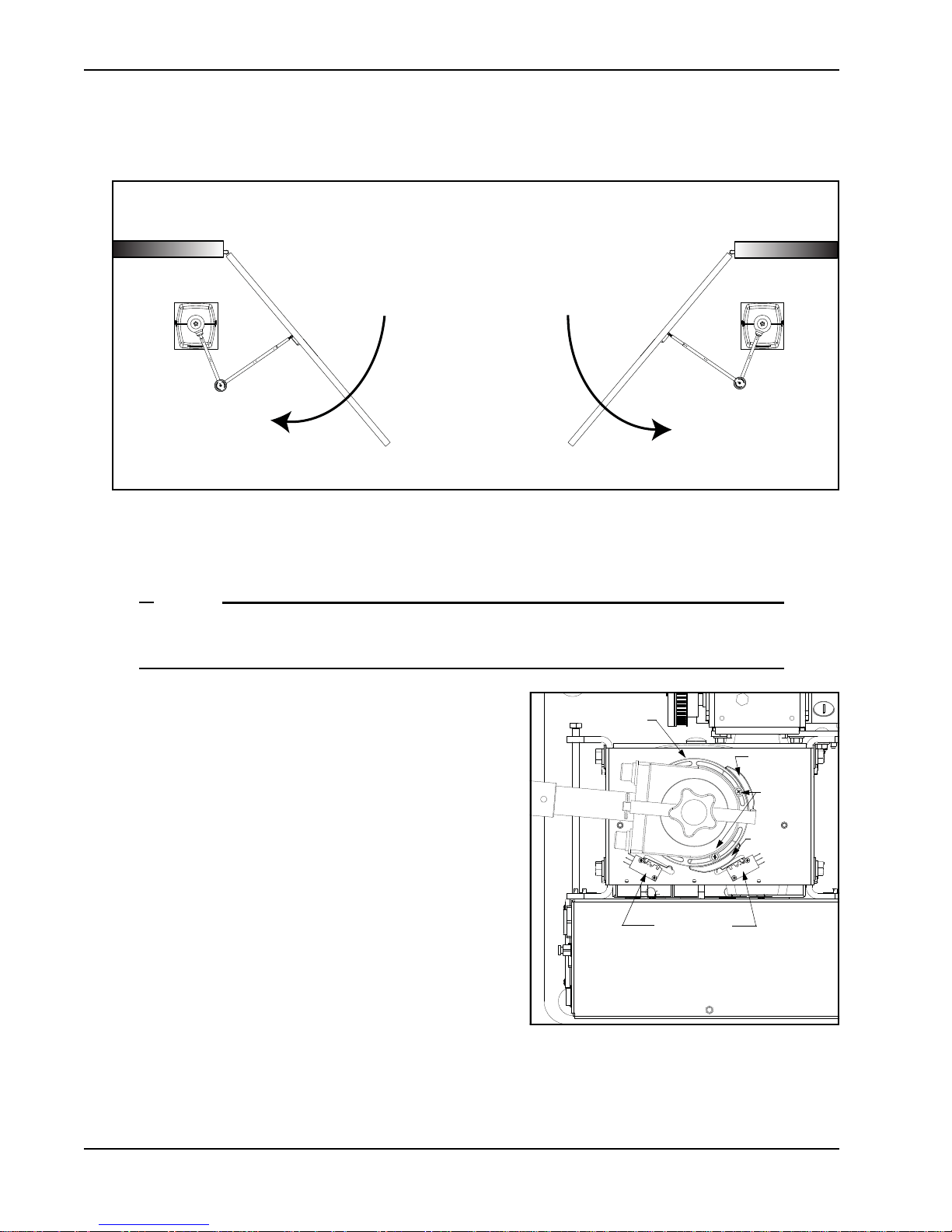
Left hand OPEN
Right hand OPEN
PUBLIC SIDE
SECURE SIDE
NOTE
Limit switches
Figure 1-12.
Loosen
screws
Limit plate
Limit cam
Limit cam
Adjusting the Limit Switches
Figure 1-11.
1. Determine whether the gate operator is a right-hand operator or left-hand operator. See Figu
on the secure side of the gate. If the gate opens to the right, it is a right-hand operator.
For a right-hand operator, the OPEN switch is the left limit switch as shown in Figure 1-12
The opposite occurs in a left-hand operator; the OPEN switch becomes the right limit switch.
2. To adjust the limit cams, use a Phillips-head screwdriver
and loosen the fastener that secures each limit cam to the
limit plate.
3. Manually, open and close the gate. Move the limit cams
so they trip the appropriate limit switch at the full OPEN
and full CLOSE positions.
4. Secure the limit cams by retightening the two Phillipshead scr
A fin on the limit plate
ensures the limits always
the gate is struck and the taper clamp slips.
Note:When reassembling the taper clamp, make sur
plate fin is seated into the slot on the taper clamp.
ews.
fits into the taper clamp. This feature
track the gate arm position even if
e the limit
re 1-11. Stand
1-10 SwingSmart - Installation, Operation and Maintenance Manual Revision A
Page 29
Completing Gate Arm Installation
To weld the linkage arms:
Weld a 1/8-inch fillet
around the tubing joint.
To use fasteners: Drill holes with a 17/64-inch drill bit and connect
arms with 1/4 - 20 UNC fasteners.
1/8”
1/8”
DRILL & BOLT (2x)
WELD
1A
1B
Set screw
Elbow joint
1A
1B
NOTE
Gate Bracket and Linkage Arms
Revision A Installation 1-11
Figure 1-13.
1. Drill & bolt (or weld the arms) to complete arm installation. See Figure 1-13. Paint welded areas to prevent
rusting. Consider the following when determining whether to
drill and bolt or weld the linkage arms:
DRILL & BOLT: Use at sites where fire bans do not permit outdoor welding and where the security
level is not high. In the event of a gate strike, bolts will shear and prevent full force impact to the gear
box. Damage is usually sustained to the less costly equipment such as th
WELD: Use at sites where the security level is high and the likelihood of gate strikes negligible. Be
e gate linkage arms.
aware, if you weld the arms and a gate strike occurs, damage may occur to the gearbox and linkage
arm assembly
.
For sites where incident of gate strikes are high, HySecurity recommends setting the elbow with
a slight offset at the full close position. Use the supplied set screw to prevent the arm from locking. The intent of the offset is that, upon gate strike, the elbow will bend and the taper clamp
will slip, minimizing damage to the gearbox and operator.
Page 30
Top and bottom covers need to be
evenly aligned. Gap should be less
than ¼-inch.
Cover
fastener
Cover
fastener
Bottom cover
Top cover
Elbow joint
2
Gate Bracket and Linkage Arms
NOTE
CAUTION
!
The two elbow joint cover fasteners are shipped with the covers.
2. Place the covers over the elbow joint.
3. Align the mounting holes and cutouts in the covers with the gate arms.
4. Make sure the gap between the top and bottom covers is evenly aligned. See Figure 1-14.
5. Insert the two fasteners and secure the covers.
It is critical that you install the elbow joint covers to comply with UL325 Safety Standards. The
elbow joint is considered a pinch point and serious injury may occur if the elbow joint covers
are not secured properly to the gate arms.
1-12 SwingSmart - Installation, Operation and Maintenance Manual Revision A
Figure 1-14.
Page 31

Setting the Taper Clamp
Loosen
Tighten
Retract
45° angle
Simulate a gate strike
with ~ 100 lbs. of
force.
NOTE
Gate Bracket and Linkage Arms
Figure 1-15.
Setting the taper clamp with the gate closed impedes traffic flow. If vehicles need to pass
through the gate area, delay setting the taper clamp until after the operator has been configured
to run. Refer to Chapter 3, Configuring the Setup Menu.
1. Manually, swing the gate half way between the open and closed position (approximate 45° angle).
2. Turn the taper clamp handle clockwise to hand-tighten the assembly. A large am
ount of torque is not
required in order to obtain a tight clutch setting.
3. Push the gate end with approximately 100 pounds of force to simulate a gate strike. If the clamp taper
slips, use the taper handle to furthe
r tighten the assembly.
4. Continue to adjust the taper clamp until no slippage occurs.
5. Retract and center the taper clamp handle.
Revision A Installation 1-13
Page 32

Gate Bracket and Linkage Arms
This page intentionally blank.
1-14 SwingSmart - Installation, Operation and Maintenance Manual Revision A
Page 33

Power
DANGER
!
NOTE
Chapter 2
TEP-BY-STEP
S
1. Install the earth ground.
2. Wire AC Power.
3. Connect DC Power.
INSTALLING THE EARTH GROUND
An earth ground refers to the grounding rod and accompanying equipment ground which need to be installed
to safeguard against potential electrical shock and damage to personnel and equipment.
The potential for lightning discharge exists with all gates, fences and gate operators. National Electric Code (NEC) requires a separate earth ground in addition to the required equipment ground.
HySecurity recommends grounding the operator with a separate earth ground connected to a ground rod to
assure proper operation and shield it against electromagnetism and other electrical signals that may cause
erratic operation with or damage to the Smart DC Controller.
If you do not ground the operator with a separate earth ground rod, you risk voiding the
Limited Warranty.
For earth grounding requirements, refer to the National Fire Protection Association (NFPA) 780 - Standard for
the Installation of Lightning Protection Systems. Highlights of the standard include.
• The ground rod is a solid copper ground rod: minimum requirements: ⅝" (16mm) diameter and 10 feet
(3m) in length.
• The ground rod is driven into the earth (refer to local codes for proper depth requirements).
• The ground rod is electrically bonded to the chassis with a single length of un-spliced 6AW
less than 3 feet (91cm) long.
• Local jurisdictions may impose additional requirements above the NEC and NFPA 780. Consult the local
codes
and regulations regarding requirements in your area.
G copper wire
Revision A 2-1
Page 34

Wiring AC Power
Buzzer/Alarm
Emergency Stop Button
DC Power Switch
Up is ON, Down is OFF
AC Circuit Breaker
115VAC Convenience Outlet
High Voltage Junction Box Cover
AC Input Wiri ng
AC Power Switch
Up is ON, Down is OFF
High Voltage Protection Cover
Smart DC Controller Display
DANGER
!
WARNING
!
Lug nut
Consult local
codes for
proper depth.
3 ft
Run ground wire
through concrete
base.
Figure 2-1.
Take the following steps to comply with NEC and NFPA 780 standards:
1. Install a grounding rod per local building codes. See Figure 2-1.
2. Attach a large earth ground wire (6AWG) from the grounding rod to
the lug nut on the base of the
chassis. Depending on whether you’ve
installed the operator at a new or existing site,
• Ne
w site: Run the 6AW
G wire through the concrete base and into
the cutout on the chassis base.
• Existing site: Run the 6AW
G wire beneath the rear cover. Make
sure the covers align and side latches lock properly.
Properly grounding the gate operator is critical to gate operator
performanc
e and the life of its electrical components. Use sufficient wire
size during installation. Refer toWiring 115VAC Power or Wiring 208/
230VAC Power.
WIRING AC POWER
Turn off AC power at the source (circuit breaker panel) before accessing the wires in the SwingSmart junction box. Follow facility Lock Out/Tag Out procedures. Make sure both the DC and AC
power switches, on the side of the SwingSmart control box are in the off position. See Figure 2-2.
Wiring of gate operators must conform to the NEC standards and comply with all local codes.
2-2 SwingSmart - Installation, Operation and Maintenance Manual Revision A
Figure 2-2.
Page 35

Wiring AC Power
NOTE
NOTE
Wiring 115VAC Power
For standard 115VAC power connection:
• Verify AC power supply wires and low voltage (12V & 24V accessory power wir
separate conduits.
The higher voltage from the AC power supply may cause interference and anomalies in SwingSmart operation if the high and low voltage wires are routed through the same conduit.
• Make sure proper wiring is being used. The following table shows the maximum allowable wire run from
the power source to the operator for various wire sizes:
AC Power 14 gauge wire 12 gauge wire 10 gauge wire 8 gauge wire
One operator 115V 610 ft (185 m) 1000 ft (300 m) 1550 ft (475 m) 2500 ft (755 m)
Two operators 115V 305 ft (95 m) 500 ft (150 m) 775 ft (240 m) 1250 ft (380 m)
es) run through two
Figure 2-3.
To connect to 115VAC power, take the following steps:
1. Make sure the AC power is turned off at its source and the DC and AC power switches on the operator are
in the off position.
2. Access the input pow
er wires and convenience outlet wire
s by remo
ving the two Phillips-head screws that
secure the high voltage junction box cover.
The convenience outlet wires are solid copper and are labeled and bound together to keep them
separate from the AC power switch wires.
3. Wire nut or crimp bond the power supply wires to the black and white lead wires coming from the AC
power switch (no label). See Figure 2-3.
4. Wire nut or crimp bond the equipment ground wire to the green ground wire in the junction box.
5. To activate the 115VAC convenience outlet, include the black and white outlet lead wires and the green
ground wire in the connections made ab
6. Neatly organize all wire connections and replace the high voltage junction box cover. S
ove.
ecure it with the two
Phillips-head screws.
Revision A Power 2-3
Page 36

Wiring AC Power
CAUTION
!
30V
Figure 2-4.
Voltage selector switch
set to 230V.
Wiring 208/230VAC Power
All SwingSmart operators are shipped from the factory as 115VAC units. When connecting to
208/230VAC power, the voltage selector switch on the AC power board must be moved to the
230V position or damage to the operator will occur and void the Limited Warranty.
For the 208/230VAC power connection:
• Verify AC power supply wires and low voltage (12V & 24V accessory power wires) run through two
separate conduits as discussed in Wiring 115VAC Power.
• Make sure proper wiring is being used. The following table provides the size wire for dis
the power source to the operator:
AC Power 14 gauge wire 12 gauge wire 10 gauge wire 8 gauge wire
One operator 208/230V 2440 ft (745 meters) 3900 ft (1180 meters) 6200 ft (1885 meters) 9900 ft (4950 meters)
tance (in feet) from
Two operators 208/230V 1220 ft (370 meters) 1950 ft (590 meters) 3100 ft (940 meters) 3005 ft (1500 meters)
To connect to 208/230VAC power, take the
following steps:
1. Make sure the AC power is turned off at its
source and the DC and AC powe
r switches
on the operator are in the off position.
2. Remove the High Voltage Protection cover
by unscrewing the tw
o Phillips-head screws
that secure it.
3. Toggle the voltage selector switch from 115V
to 230V. R
eplace the High Voltage cover and
secure it. See Figure 2-4.
4. Access the input power wires by removing the
two Phillips-head screws that secure the High
Voltage Junction Box Cover. See Figure 2-2.
5. Wire nut or crimp bond the power supply
wires to the black and white lead wires
coming from the AC power switch (no label).
6. Wire nut or crimp bond the equipment
ground wire to the green ground wire in the
junction box.
2-4 SwingSmart - Installation, Operation and Maintenance Manual Revision A
Page 37

Connecting DC Power
DANGER
!
Figure 2-5.
Do not connect the 115VAC convenience outlet to 230VAC power supply wires. To use the 115VAC
convenience outlet with 230VAC supply power, a separate neutral wire (white) must be run from the
power source. Follow guidelines according to the National Electrical Code Article 250.
7. Neatly organize all wire connections and secure the High Voltage Junction Box Cover with the two
Phillips-head screws.
8. Place the 230V 1Ø label on the High Voltage Junction Box Cover over the 115V 1Ø label.
CONNECTING DC POWER
To connect the DC power:
1. Turn off the DC and AC power switches.
2. Slide the plastic cover off the control box.
3. Attach the red spade connector to the battery terminal on
the DC powe
r switch. See Figure 2-5.
Note: For extended battery backup installation, refer to the
Installing the Extended B
attery Backup Kit instructions.
Important Considerations for DC-powered Operators
• Since the operator is intended to run on batteries, control of the load is important. Gates that move easily
and do not bind will drain less energy from the battery, preserving capacity for more cycles during a power
failure.
• Be certain to observe polarity when connecting the batteries or adding accessories. Reversed polarity may
result in a non-functional operator or damage to a co
If shorted, the batteries will generate a very high current. The batteries are connected in a series circuit:
Join the positive (+) terminal from one battery to the negative (-) terminal of the next battery.
• When the operator is not in use, and no AC power is connected, be sure to shut
unplug the red battery wire from it. This will prevent the batteries from slowly discharging over time.
Batteries have a finite life. As the batteries age, they will lose some of their capacity to store energy. If the
total amount of back-up capacity is critical, plan to replace the batteries after two years of use. Properly
dispose of or recycle used batteries. Refer to Hazardous Materials and Proper Disposal.
mponent. Red (+) is positive and black (-) is negative.
off the DC switch, and
Revision A Power 2-5
Page 38

Connecting DC Power
WARNING
!
NOTE
Batteries contain sulfuric acid. Acid in your eyes, on your skin, or on your clothing can cause
injury and severe burns. If batteries are dropped or damaged dispose of them properly.
• Batteries are rated to perform to capacity at certain temperatures. Variations in temperature affect
performance of the batteries. An example of amp hour performance is shown in Table 2-1. HySecurity
mounts the battery pack near the transformer to provide residual heat around the batteries which guards
against amp hour loss.
able 2-1.
T
Amp Hour - Example of Battery Performanc
e
Temperature Capacity
77°F (25°C) 100
32°F (0°C) 75
10°F (-12°C) 50
• HySecurity uses a permanently sealed AGM-type battery which needs no maintenance over its life span.
Batteries are protected from over discharge by a low voltage sensing circuit. The charger circuit regulates to
only allow high charger output when the battery is partially discharged. The charger circuit automatically
reduces the output to near zero as the batteries become fully charged.
The SwingSmart operator stores all User and Installer Menu settings in non-volatile memory
(EEPROM). Whatever configurations exist, if power loss occurs, are saved and reinstated once
power is restored.
2-6 SwingSmart - Installation, Operation and Maintenance Manual Revision A
Page 39

Connecting DC Power
50 AH
50 AH
Battery
Battery
DC power switch in
the off position
AC power switch in
the off position
DANGER
!
Figure 2-7.
Loosen tray
screws (2x)
Remove tray
screws (2x) and
rotate the tray
down to
remove the
batteries.
Installing the Extended Battery Backup Kit
Figure 2-6.
HySecurity offers extended DC power back up via two 50AH batteries. Contact HySecurity parts department
to order extended battery backup
kit (P/N MX001810).
To install the extended battery backup kit:
1. Turn off the DC and AC power switches.
2. Unlock side latches to remove the SwingSmart front cover.
Remove the two Phillips-h
ead screws and the two wing nuts
that secure the rear cover. Set the covers aside.
3. Cut the two black zip ties which secure the 8AH batteries to
the tray.
4. To
access the 8AH batteries and disconnect its wires, remove
the two screws closest to the motor and loosen the other
two
screws that secure the support tray as shown in Figure 2-7.
5. Carefully rotate the support tray to access the battery wir
es.
Lift the 8AH batteries from the support tray. Disconnect the black and blue wires and set the 8AH
batteries aside.
6. Return the support tray to it’s original position and secure it properly.
Make sure both the left and right 8AH DC battery wires are disconnected. Remove the batteries
from the unit and properly store or discard them. Refer to
. Never mix battery sizes, types, or brands. HySecurity strongly recommends that only sealed
posal
AGM style batteries be used.
Revision A Power 2-7
Hazardous Materials and Proper Dis-
Page 40

Connecting DC Power
Black
Blue
Red
Figure 2-8.
CT 0 (OFF)
CLOSE TIMER
OPEN
CLOSE
STOP
MENU
RESET
PREV
NEXT
SELECT
1. Start at a gate status
display.
2. Access the User
Menu, by pressing
MENU twice.
3. Access the Installer
Menu, by
simultaneously
pressing OPEN and
RESET. Release the
buttons.
4. Use NEXT to
navigate to the menu
display. Change the
setting using the
SELECT and NEXT
buttons.
7. Place the 50AH battery tray
between the chassis posts and
secure it using the four fasteners
provided in the kit. See
Figure 2-8.
8. Situate the two 50AH batteries
on the tray.
9. Attach the blue wire from the
red terminal on one 50AH
y to the black terminal on
batter
other 50AH battery.
10. Run the 8AH wire harness
throu
gh hole in
the 8AH
battery support tray.
11. Using the wires attached in the
50AH bat
tery kit, attach
wire to the red positive terminal
on the 50AH battery. Connect
its opposite end to the red lead
exiting the support tray.
Connect the black wire to the
black negative terminal on the
50AH battery. Connect its
opposite end to the black lead
exiting the support tray.
12. Access the Installer Menu on the
Smart DC Controller.
13. Change the Battery Setting (BT)
in the I
nstaller M
number 1 (Extended). Follow
the steps in the menu tree
shown here.
enu to a
the red
HYSECURITY
GATE CLOSED
CLOSE
OPEN
NEXT
PREV
STOP
SELECT
MENU
RESET
2-8 SwingSmart - Installation, Operation and Maintenance Manual Revision A
UC 2
USAGE CLASS
CLOSE
OPEN
NEXT
PREV
BT 1 (EXTENDED)
BATTERY TYPE
CLOSE
OPEN
NEXT
PREV
STOP
SELECT
STOP
SELECT
MENU
MENU
RESET
RESET
Page 41

Display and Menu Options
NOTE
Chapter 3
TEP-BY-STEP
S
1. Turn both AC and DC power switches on.
2. Configure the Setup Menu
3. Review how to use the Smart DC Controller Buttons in Menu Mode
4. Review Run Mode and Gate Status Displays
5. Access and Configure User Menu Options
• Adjust the Close Timer
• Set the Time and Date
• Set the AC Power Loss Gate Function
• Adjust the Display Contrast
6. Access and Configure Installer Menu Options
• Set the Open and Close Gate Speed
• Adjust IES Sensitivity
• Enable Fire Department Access
• Reinstate Factory Defaults
INITIAL SETUP
Once you’ve completed the installation of the SwingSmart operator and attached the wired accessories, you’re
ready to program the operator. Two different approaches exist:
• Connect a laptop computer to the USB or serial (RS-232) por
operator menu configurations via the START software.
Use a laptop computer at your place of business to conveniently download the free START software from www.hysecurity.com before heading out into the field. A START User Guide is also
available online.
• Manually navigate through the User and Installer Menus using the buttons located on the Smart DC
Controller. The instructions for performing this second option are provided in this section.
t and upload the
gate settings and set the
Revision A 3-1
Page 42

Initial setup
Figure 3-1.
DC Power
Switch
AC Power
Switch
NOTE
NOTE
Turning Both Power Switches On
One AC and one DC rocker power switch are located on the outside edge of the control box.
Refer to Figure 3-1.
1. Turn both power switches ON. An audible beep occurs and a red light
sates next to
pul
indicates the system is functioning.
Note:If AC power is lost, the rate of flashing slows down. Other indicator
lights are described below.
2. The software version briefly appears on the LCD display and the
display settles on one of the following modes:
the OPEN button on the Smart DC Controller which
• Gate status - indicates the operator is in R
un Mode. Refer to Run
Mode.
• Usage class - indicates that the Setup Menu, which consists of four
sequential displays, needs to be programmed. Refer to Configuring
tup Menu.
the Se
• Error message - indicates a problem exists with the operator which
needs to be resolved
before the operator can function properly.
Refer to Smart DC Controller Troubleshooting.
The Smart DC Controller can be powered when either switch is turned on. However, the operator is a DC-powered unit and runs on its batteries. If the DC power switch is off, the operator
will not function (even though the AC power switch is on).
The flashing red indicator light next to the OPEN button on the Smart DC Controller is considered the heart
beat of the system. It indicates that the electronics board is receiving power. When AC power is lost, the rate of
flashing slows down. Another indicator light, above the display, is multi-colored and corresponds to the action
that the operator is performing:
• Green - the operator is stopped.
• Flashing yellow - the operator is running.
• Red - the operator has experienced an error.
• Not lit - AC power is lost. But, the indicator light can be lit and address the state of the operator if the
SHOW LEDs button is pressed.
When the operator is connected to AC power and the unit is turned on, the charge level of the
battery is being monitored and maintained. On a solar-powered operator, the AC power switch
connects and disconnects the DC power from the solar panels.
3-2 SwingSmart - Installation, Operation and Maintenance Manual Revision A
Page 43

Initial setup
Pressing SELECT
causes the upper two characters to blink,
which indicates the display is ready to
accept changes to a menu setting.
Press SELECT a second time to accept
what appears on the display. The entry
mode is complete when the two characters
stop blinking.
Pressing PREV
moves to the previous
menu selection.
Pressing NEXT
advances through the next available
menu selection.
Pressing RESET
resets faults and
returns to Run
Mode. A gate
status display
appears.
Note: The
RESET button
cannot be used to
exit Menu Mode.
Pressing MENU
returns to Run Mode and a gate
status display appears.
Note: The MENU button does
not function while the selection
is still blinking.
Two blinking characters
indicate that the display
will accept changes.
Using the Smart DC Controller Buttons In Menu Mode
The buttons on the Smart DC Controller let you navigate, change, or clear the information in the display
menus. Refer to Figure 3-2.
The buttons with text above and below are variable function keys (VFK). Use these buttons to enter or change
operational data and navigate through the User and Installer Menus. The singular use of a variable function key
is dependent on operator mode. Three different modes exist:
• Run Mode - gate is operational awaiting commands. Refer to Using the Smart DC Controller Buttons In
RUN Mode.
• Menu Mode - motor disengages and operator commands are ignored. Data entry, menu navigation, and
men
u selection can be accomplished via th
using the USB port.
• Fault Mode - errors, faults or alerts appear on the display. S
button while more serious faults require the RESET button or cycling power, and then pressing RESET.
Faults indicate a need for diagnosis and resolution. Refer to Smart DC Controller Troubleshooting.
e Controller buttons or through a START software connection
ome errors or faults can be reset with the STOP
Revision A Display and Menu Options 3-3
Figure 3-2. Function of the Smart DC Controller Buttons in Menu Mode
OPEN
PREV
CT 0 (OFF)
CLOSE TIMER
CLOSE
NEXT
STOP
SELECT
MENU
RESET
Page 44

Initial setup
UC 0
USAGE CLASS
OPEN
CLOSE
STOP
MENU
RESET
PREV
NEXT
SELECT
Selections:
1 - Single-family residential up to
four units.
2 - Multi-family, hotel, etc.
3 - Industrial use, not for general
public access.
4 - Guarded and monitored facility
or location, not for general public.
Configuring the Setup Menu
The USAGE CLASS display appears the
first time power is supplied. See Figure 3-3.
f a gate status display appears, the Setup
Note:I
Menu has already been configured. Refer to
Understanding Gate Status Displays
.
Four sequential displays present
information which must be configured
before SwingSmart will function. Once the
configuration is complete, the information
is retained even when a power loss occurs.
Note:Programming the Setup Menu is usually
a one-time occurrence unless fac
tory defaults
are reinstated through the Installer Menu.
Refer to Reinstating Factory Defaults.
To navigate within the Setup Menu, use the
SELECT, NEXT, and PREV buttons. All
menu options cycle, so you eventually return
to the first menu option by continually
pressing the NEXT or PREV key.
From the USAGE CLASS display, take the
following steps:
1. Press SELECT.
The two top characters blink.
2. Press NEXT.
Continue to press NEXT to view all
the selections.
3. When
the desired selection appears,
press SELECT.
The blinking charac
ters become static.
4. Press NEXT.
Advance to the next menu display.
5. Continue to configure each menu
display that appears.
An audible beep occurs as the gate status
display appears when the initial setup is
complete. The operator enters Ru
n Mode.
Note:Complete the gate installation. If you
’t already done so, refer to Setting the
haven
Ta p e r C l a mp in Chapter 1.
SH 0
GATE HANDING
CLOSE
OPEN
NEXT
PREV
WT 0
GATE WEIGHT (LB)
CLOSE
OPEN
NEXT
PREV
LN 0
GATE LENGTH (FT)
CLOSE
OPEN
NEXT
PREV
HYSECURITY
GATE CLOSED
CLOSE
OPEN
NEXT
PREV
Selections:
0 - No Handing set. Gate will not
move until handing is set.
R - Right-hand gate opening.
Looking at the gate from the
MENU
STOP
SELECT
RESET
operator side, it opens to the right.
L - Left-hand gate opening.
Looking at the gate from the
operator side, it opens to the left.
Selections:
0 - not set
1 - Gate weight: 0 to 300lbs.
2 - Gate weight: 301 to 600lbs.
MENU
STOP
RESET
3 - Gate weight: 601 to 800lbs.
4 - Gate weight: 801 to 1300lbs.
SELECT
Selections:
0 - not set
1 - Gate length: 0 to 8ft.
2 - Gate length: 8 to 12ft.
MENU
STOP
SELECT
RESET
3 - Gate length: 12 to 16ft.
4 - Gate length: 16 to 20ft.
Note: The GATE CLOSED
display is an example.
Any one of three gate status
displays could appear depending
STOP
SELECT
MENU
RESET
on the gate operating mode. See
Run Mode.
Figure 3-3. Setup Menu
3-4 SwingSmart - Installation, Operation and Maintenance Manual Revision A
Page 45

Run Mode
HYSECURITY
GATE OPEN
OPEN
CLOSE
STOP
MENU
RESET
PREV
NEXT
SELECT
Figure 3-4. Gate Status Displays
NOTE
RUN MODE
Gate status displays appear when the operator is ready and waiting for a gate operation command. When the
menu display is flashing “GATE OPENING” or “GATE CLOSING” a command has been received and the
operator is responding appropriately. The command may come from a variety of sources: a card reader, pushbutton remote, or recognition of a vehicle passing over a loop detector. In all cases, the operator “runs” the
motor when it receives a gate operation command.
Understanding Gate Status Displays
HYSECURITY
GATE CLOSED
CLOSE
OPEN
NEXT
PREV
STOP
SELECT
MENU
RESET
HYSECURITY
GATE STOPPED
CLOSE
OPEN
NEXT
PREV
STOP
SELECT
MENU
RESET
Three gate status displays are shown in Figure 3-4. Each indicates the position or status of the gate. When
accessing the User or Installer menus, you must begin at one of these gate status displays.
To access the User or Installer menus, the motor cannot be engaged and the gate cannot be
moving.
Revision A Display and Menu Options 3-5
Page 46

Run Mode
HYSECURITY
GATE CLOSED
OPEN
CLOSE
STOP
MENU
RESET
PREV
NEXT
SELECT
Pressing STOP
stops gate travel.
Pressing OPEN
opens the gate.
Pressing CLOSE
closes the gate.
Pressing RESET
clears error codes and
returns to Run Mode.
Pressing MENU
scrolls through operator status displays
and accesses the User Menu. The
CLOSE TIMER display appears which
presents the first of twelve
programmable displays.
Note: Pressing the MENU button
twice, bypasses the operator status
displays.
Using the Smart DC Controller Buttons In RUN Mode
The Run Mode buttons are distinguished by the fact that their name appears above each button. The buttons
with text above and below are variable function keys (VFK) and function differently depending on the mode of
the operator. Three different modes exist:
• Run Mode - gate is operational awaiting commands.
• Menu Mode - motor disengages and operator commands are ignore
selection can be accomplished using the Smart DC Controller buttons or through a START software
connection via the USB port. Refer to Using the Smart DC Controller Buttons In Menu Mode.
• Fault Mode - errors, faults or alerts appear on the display. S
ome errors or faults can be reset with the STOP
button while more serious faults require the RESET button or cycling power, and then pressing RESET.
Faults indicate a need for diagnosis and resolution. Refer to Smart DC Controller Troubleshooting.
d. Menu navigation and menu
Figure 3-5. Function of Smart DC Controller Buttons in Run Mode
3-6 SwingSmart - Installation, Operation and Maintenance Manual Revision A
Page 47

Run Mode
SOFTWARE VERSION
H5.##
DUAL GATE
<MASTER>
OT<12>D
SWINGSMART DC20
<LEFT> HAND
UC <2>
USAGE CLASS
BT <0>
STANDARD BATTERY
D <32>.0 VDC
BATTERY VOLTAGE
CC<002600>
CYCLE COUNT
NOTE
Viewing Operator Status Displays
Eight operator status displays appear in two second intervals and show pertinent information which provides a
quick overview of the operator’s status or configurations. Refer to Figure 3-6.
Items shown inside the brackets < > are variables that may change depending on operator configurations. The examples shown in Figure 3-6 may appear differently on your operator.
Variables Description
The software version and revision
number are hard-coded in the Smart
DC Controller.
Displays the software version which is
useful as a maintenance tool and
required when calling Technical
Support.
MASTER or SLAVE
(This display only appears when the
operator is used in bi-parting gate
systems.)
1, 2, 3, 4, 5, 6, 7 and
11, 12, 13, 14
LEFT or RIGHT Designates which way a gate opens
1, 2, 3, or 4 Displays the operator’s Usage Class
Indicates, in a dual gate setting,
whether the operator is set to Master
or Slave. The setting is assigned in the
Installer Menu.
Indicates the software configuration
number which is preset at the factory
and cannot be changed.
viewed from the operator. If it swings
to the left, it is a left-hand gate. Gate
handing is established in the initial
Setup Menu.
designation per UL 325 standards.
Identifying Gate
Refer to
Operator Category and Usage
0, 1, or 2
0 = 8AH
1 = 50AH
2 = 110AH
Confirms the operator’s battery type
which is assigned through the Installer
Menu.
Revision A Display and Menu Options 3-7
Number varies depending on the
voltage that the charger is providing.
Number varies depending on open
and close cycles. One cycle equals a
full open and close sequence.
Figure 3-6. Operator Status Displays
Displays the actual voltage that the
batteries are delivering to the Smart
DC Controller.
Displays the number of cycles the gate
operator has incurred. Similar to an
odometer, it resets to zero after
999,999 cycles.
Page 48

User Menu
CT 0 (OFF)
CLOSE TIMER
OPEN
CLOSE
STOP
MENU
RESET
PREV
NEXT
SELECT
USER MENU
The User Menu consists of twelve functions which can be modified using the Smart DC Controller buttons.
Refer to Using the Smart DC Controller Buttons In Menu Mode.
To access the User Menu, take the following steps:
1. At a gate status display, press the MENU button.
Eight operator status displays scr
CLOSE TIMER display appears.
Note:To access the User Menu, the operator must be in
Run Mod
e. The motor cannot be engaged and the gate
cannot be moving.
2. To bypass the operator status displays and access the
User Menu, press th
e MENU button twice.
The CLOSE TIMER display appears.
oll past and the
In the pages that follow, a detailed view of the more commonly used menus is pro
vided:
• Adjusting the Close Timer
• Setting the Time & Date
• Setting the AC Power Loss Gate Function
• Adjusting the Display Contrast
Table 3-1 on page 3-13 describes the User Menus, supplies the factory defaults, and references the hard-wire
connections.
For information on how the menu buttons function, review Using the Smart DC Controller Buttons In Menu
Mode.
3-8 SwingSmart - Installation, Operation and Maintenance Manual Revision A
Page 49

User Menu
CT 0 (OFF)
CLOSE TIMER
OPEN
CLOSE
STOP
MENU
RESET
PREV
NEXT
SELECT
Adjusting the Close Timer
The close timer assigns how many seconds will pass before the operator initiates closure of a fully opened gate
after all open commands and reversing sensor inputs have ceased. Every gate operator needs to have the close
timer set to a specific number of seconds unless a hard-wired closing device is connected to the unit such as a
push-button station.
To adjust the time (1 to 99 seconds) it takes before the operator initiates gate closure, take the following steps:
1.
At a gate status display, press the MENU button
twice.
This accesses the User Menu and the CLOSE TIMER
display appears.
2. Use the SELECT and NEXT or PREV buttons to
navigate and
change the number on the display
Note:Keep the close time at zero if gate personnel operate
the gate or the owner plans to use a re
mote control.
3. To exit the User Menu, press the MENU button.
The gate status appears in the display indicating you
returned to Run M
have
ode.
.
Revision A Display and Menu Options 3-9
Page 50

User Menu
HYSECURITY
GATE CLOSED
OPEN
CLOSE
STOP
MENU
RESET
PREV
NEXT
SELECT
1. Start at a gate status
display.
2. To access the User
Menu, press the
MENU button twice.
3. Press NEXT until
the SET CLOCK
display appears. Use
the navigational
buttons to select 1.
4. Change the time
and date using the
NEXT and SELECT
buttons.
Setting the Time and Date
A feature of the Smart DC Controller is its 24-hour, 365 day clock. Make sure it is set to the appropriate time
zone. An accurate time and date allows the diagnostic log to date stamp operational data which indicates when
Alerts, Faults and Errors occur. The log helps in troubleshooting and can be viewed via a laptop connected to
the USB or RS232 port. For more information, refer to Smart DC Controller Troubleshooting.
To set or adjust the time or date, take the following steps:
1.
At a gate status display, press the MENU button
twice. This accesses the User Menu and the
CLOSE TIMER display appears.
2. Press
3. Press SELECT.
4. Press NEXT or PREV to change the number to 1.
5. Press SELECT to accept the display.
6. The date and time display appears. Use the
NEXT or PREV until the SET CLOCK
display appears.
CL blinks.
SELECT and NEXT buttons in the same
manner as before
to adjust the date and time.
CT 0 (OFF)
CLOSE TIMER
Note:A date or time field must be blinking before
can be changed.
it
7. To accept what appears on the date and time
display, press SELECT
8. To exit the User Menu, press the MENU
button. A gate status appears in the display
indica
ting you have returned to Run Mode.
.
Note:A lithium coin battery supports the clock so the
date and time is retained ev
en when the main power is
turned off. Replace the battery about every five years
with a DL 2025, DL 2032 or CR 2025 or CR 2032
battery. Refer to Clock Battery Replacement.
CLOSE
OPEN
PREV
OPEN
PREV
OPEN
PREV
STOP
SELECT
NEXT
CL 1
SET CLOCK
CLOSE
STOP
SELECT
NEXT
01/05/01 00:00
^^
CLOSE
STOP
SELECT
NEXT
MENU
MENU
MENU
RESET
RESET
RESET
3-10 SwingSmart - Installation, Operation and Maintenance Manual Revision A
Page 51

User Menu
AP 0 AC LOSS
UPS FAIL OPEN
NOTE
AP 1 AC LOSS
UPS FAIL CLOSE
AP 2 AC LOSS
AUTO OPEN
AP 3 AC LOSS
NO CLOSE TIMER
Setting AC Power Loss Gate Function
The setting in the AC LOSS display determines what action the operator performs during an AC power loss.
The settings help reduce drain on the battery. You can choose between four settings depending on customer
preferences.
DC Solar Powered units can only be set for AP0 or AP1.
Normal gate functions continue until the system detects a battery voltage drop below 21V.
DEAD BATTERY appears on the display and the gate automatically o
button CLOSE command will close the gate and any open command will re-open the gate.
If the battery continues to diminish and the system detects 18V or less, the system initiates
an automatic open cycle. Any new open or close command is ignored and the LCD appears
blank. The system remains in this disabled state until reset or the battery recovers to 24V.
Normal gate functions continue until the system detects a battery voltage drop below 21V.
DEAD BATTERY appears on the display and the gate automatically closes. The gate can be
opened by a special sequence of a STOP input followed by an OPEN push-button or directly
opened with the Fire Department Open command. Any push-button CLOSE command will
close the gate. If the battery continues to diminish and the system detects 18V or less, the
system initiates an automatic open cycle. Any new open or close command is ignored and
the LCD appears blank. The system remains in this disabled state until reset or the battery
recovers to 24V.
pens. Any push-
The operator automatically opens the gate five seconds after it detects an AC power loss. The
gate remains open until AC power is restored. Any push-button CLOSE command will close
the gate and any open command will open the gate. When the battery voltage drops below
21V or less, the system initiates an automatic open cycle. The gate will remain open until
the battery recovers to 24V.
The operator initially does nothing after it detects AC power loss until it receives an open
command. Once an open command is received, the operator opens and remains in that state.
Any push-button CLOSE command will close the gate and any open command will open
the gate. When the battery voltage drops below 21V or less, the system initiates an automatic
open cycle. The gate will remain open until the battery recovers to 24V.
Revision A Display and Menu Options 3-11
Page 52

AP 0 (AC LOSS)
UPS FAIL OPEN
OPEN
CLOSE
STOP
MENU
RESET
PREV
NEXT
SELECT
User Menu
LD 5
LCD CONTRAST
OPEN
CLOSE
STOP
MENU
RESET
PREV
NEXT
SELECT
To designate what you want the operator to do during an AC power loss, take the following steps:
1. At a gate status display, press the MENU button
twice. This accesses the User Menu and the CLOSE
TIMER display appears.
2. Press NEXT until the AC LOSS display appears.
3. Use the SELECT and NEXT buttons to navigate and
change the number on the
display. Review Using the
Smart DC Controller Buttons In Menu Mode.
4. To exit the User Menu, press the MENU button. A
gate status appears in the display indicating you
have
returned to Run Mode.
Adjusting the Display Contrast
The display contrast can be adjusted from 1 to 9 to increase visibility and ease of use. It is set at the factory to
level 5. The text becomes darker as you go up the scale.
To adjust the contrast (1 to 9), take the following steps:
1.
At a gate status display, press the MENU button
twice. This accesses the User Menu and the CLOSE
TIMER display appears.
2. Press
NEXT until the LCD CONTRAST display
appears.
3. Use the SELECT and NEXT buttons to navigate and
change the number on the
display.
4. To exit the User Menu, press the MENU button. A
e status appears in the display indicating you
gat
have
returned to Run Mode.
3-12 SwingSmart - Installation, Operation and Maintenance Manual Revision A
Page 53

User Menu
HC 0 (OFF)
HOLD TO CLOSE
HO 0 (OFF)
HOLD TO OPEN
AP 0 AC LOSS
UPS FAIL OPEN
CT 0 (OFF)
CLOSE TIMER
RO 0 (OFF)
RADIO OPEN/CLOSE
Associated
DC Controller
Connections
Menu Tasks and Explanations
Not applicable (N/A)
device is being used.
Assign how many seconds before the open gate initiates
closure.
Note: The CLOSE TIMER display does not appear when
Keep the setting at 0 if a hard-wired, push-button control
the HOLD TO CLOSE is set to 1.
COM
STOP
transmitted.
Set to 0 produces a gate closure when a momentary signal is
OPEN
CLOSE
lose timer and causes its menu to disappear.
Set to 1 if a constant hold to close signal, such as a push
button control, is being used. A setting of 1 also deactivates
the automatic c
You must set HC to 1 to comply with UL 325 Type D
protection. Refer to Table Notes.
COM
OPEN
Similar to HOLD TO CLOSE, but configures the Open
push button for a constant-hold function.
comply with UL 325 Type D protection. Refer
1 = Constant hold open push button required. You must set
HO to 1 to
0 = Momentary open signal
to Table Notes
Dependent on setting.
The setting designates what action the gate performs during
an AC power loss. Refer to Setting AC Power Loss Procedures
COM
RADIO OPEN
Configures radio input for open only (0) or at setting 1
is fully open.
adds the capability for radio input to close the gate when it
Setting Options
Bold = Factory Settings)
(
0 = Timer disabled
1 second to 99 seconds
0 = off
1 = on
0 = off
1 = on
0 = UPS FAIL OPEN
1 = UPS FAIL CLOSE
2 = AUTO OPEN
3 = NO CLOSE TIMER
0 = off
1 = on
Table 3-1. Smart DC Controller - User Menu Functions
Display
User Menu
CT 0 (OFF)
CLOSE TIMER
Ref.
No.
*
1
2
3
4
5
3-13 SwingSmart - Installation, Operation and Maintenance Manual Revision A
Page 54

User Menu
DA 0 (OFF)
DRIFT CLOSE ALERT
Associated
DC Controller
Connections
Menu Tasks and Explanations
(N/A)
Controls the warn-before-operate buzzer and can be
configured three ways:
begins and continues through entire gate travel.
Set to 1: Buzzer beeps for 3 seconds before gate motion
Set to 2: Buzzer beeps for 3 seconds before gate motion
2 seconds of gate travel.
begins and continues for
Set to 0: Buzzer is disabled. Set at 0 the buzzer will still beep
ults, errors, or entrapment are detected.
when alerts, fa
WARNING: Do NOT cut the wires to the buzzer or
unplug it as the operator will not be in compliance with UL
Failure to comply may result in serious injury or
325.
death.
(N/A)
operate” buzzer alarm, and then initiates a closure if the
gate is forced open and the closed limit switch disengages.
Intended for highly secure facilities.
Set to 1, the operator sounds the 3-second “warn before
The motor restarts to secure the gate. If the gate does not
fully close within 4 seconds, the motor turns off and the
(N/A)
alert buzzer sounds for 30 seconds. The display shows
ALERT 1 - FORCED OPEN.
operate” buzzer alarm and initiates an open command if the
gate is forced, or drifts, off the open limit switch. The
Set to 1, the operator sounds the 3-second “warn before
motor starts to reopen the gate. The motor runs for a
maximum of 4 seconds and, if the gate is not fully open at
the end of this period, the buzzer sounds for 10 seconds.
The display shows ALERT 2 - DRIFT CLOSED
Setting Options
Bold = Factory Settings)
(
0 = off
1 = on
2 = on
0 = off
1 = on
0 = off
1 = on
Table 3-1. Smart DC Controller - User Menu Functions
Display
User Menu
BF 2 (ON 2 SEC)
WARN BEFORE OPER
Ref.
6
No.
*
7
FA 0 (OFF)
FORCE OPEN ALERT
8
3-14 SwingSmart - Installation, Operation and Maintenance Manual Revision A
Page 55

User Menu
Associated
DC Controller
’s free START
Connections
Menu Tasks and Explanations
EYE OPEN
EYE CLOSE
EYE COM
transmitter/receiver alignment. The buzzer chirps once
when the emitter and receiver are not aligned. When the
When set to 1, the operator serves as an aide in photo-eye
emitter and receiver are aligned, the buzzer chirps twice. If
they go out of alignment again, the buzzer will chirp once.
The Alignment Mode is reset with a close-limit input or
reset input.
(N/A)
stamped with the time and date. This feature is useful to
The Smart DC Controller is equipped with a 24 hour 365
read historical operation data, which can be accessed with a
day clock; thus events of significance are logged and
computer via the USB or RS232 port. To set or adjust the
hour, minute, day or month, see Setting the Time and Date.
(N/A)
Under some extreme high or low temperature conditions, it
may be necessary to adjust the contrast of the LCD display.
The display is adjustable from 0-9 with a factory default
setting of 5.
software is required to read
USB or RS232 cable and
laptop computer with
Set this item to 1 to record all gate operator open and close
events, in addition to the normal alert, fault and error logs.
the log file.
HySecurity
manipulation.
This parameter automatically resets to the default 0 (off)
after 24 hours, which is useful when experiencing
events such as faults, errors, or menu
intermittent problems.
Set to 0, the DC Controller logs pertinent gate operator
closing device (such as a timer, loop sensor, or similar device) shall not be employed. For additional
Setting Options
Bold = Factory Settings)
(
0 = off
1 = on
0 = Display
1 = Set Clock
5
0 through 9
0 = off (standard)
1 = on (detailed)
ence-numbered menu selections:
Table 3-1. Smart DC Controller - User Menu Functions
Display
User Menu
Type D entrapment protection, an automatic
Choosing Secondary Entrapment Protection.
PE 0 (OFF)
PHOTO EYE ALIGN
Ref.
9
No.
*
10
CL 0
SET CLOCK
11
LD 5
LCD CONTRAST
12
DS 0 (OFF)
DIAGNOSTIC LOGS
Table Notes:
The following conditions apply to the indicated refer
2 & 3 For gate operators using
information, refer to
3-15 SwingSmart - Installation, Operation and Maintenance Manual Revision A
Page 56

Installer Menu
NOTE
HYSECURITY
GATE CLOSED
OPEN
CLOSE
STOP
MENU
RESET
PREV
NEXT
SELECT
UC 2
USAGE CLASS
OPEN
CLOSE
STOP
MENU
RESET
PREV
NEXT
SELECT
1. Start at a gate status display. To
bypass the Operator Status Displays,
press the MENU button twice.
The CLOSE TIMER display appears
indicating you have accessed the User
Menu.
2. To access the Installer Menu,
simultaneously, press OPEN and
RESET.
Release the buttons and the Usage
Class display appears indicating
entrance to the Installer Menu. The
USAGE CLASS display is the first
item in the Installer Menu.
INSTALLER MENU
The Installer Menu consists of several functions which can be modified using the Smart DC Controller
buttons or configured through the use of a laptop computer and the START software available from the
HySecurity website.
The Installer Menu options provide more advanced configurations for the SwingSmart operator. Access to the
Installer Menu is through the User Menu. The navigational buttons are the same in both menu modes. To
review how to use the navigational buttons on the Smart DC Controller, refer to Using the Smart DC Controller
Buttons In Menu Mode.
To access the User or Installer menus, the operator must be in Run Mode with a gate status
showing on the display. The motor cannot be engaged and the gate cannot be moving.
To access the Installer Menu, take the
following steps:
Note:Four menu items, Usage Class,
Gate Handing, Gate Weight, and Gate
Length must be configured before the
operator will function. Refer to
Configuring the Setup Menu.
In the pages that follow, a detailed view
of the more commonly used menus i
provided.
s
CT 0 (OFF)
CLOSE TIMER
• Adjusting the Open Speed
• Adjusting the Close Speed
OPEN
PREV
CLOSE
NEXT
STOP
SELECT
MENU
RESET
• Adjusting the IES Sensitivity
• Enabling the Fire Department
Override
• Reins
Table 3-2 on page 3-21 des
Installer Me
defaults, and references the hard-wire
connections.
For information on how the menu buttons function, review Using the Smart DC Controller Buttons In Menu
Mode.
tating Factory Defaults
cribes the
nus, supplies the factory
3-16 SwingSmart - Installation, Operation and Maintenance Manual Revision A
Page 57

Installer Menu
NOTE
HYSECURITY
GATE CLOSED
OPEN
CLOSE
STOP
MENU
RESET
PREV
NEXT
SELECT
UC 2
USAGE CLASS
OPEN
CLOSE
STOP
MENU
RESET
PREV
NEXT
SELECT
OS 5
OPEN SPEED
OPEN
CLOSE
STOP
MENU
RESET
PREV
NEXT
SELECT
1. Start at a gate status
display.
2. Access the User
Menu by pressing the
MENU button twice.
3. Access the Installer
Menu, by
simultaneously,
pressing the OPEN
and RESET buttons.
4. Use NEXT to
navigate to the menu
display. Change the
setting using the
SELECT and NEXT
buttons.
Adjusting the Gate Speed
The gate speed designates how quickly the gate opens and closes. The available range from 1 to 10 varies the
speed of the motor and the gate speed increases as you go up the number scale. The adjustable speed range is
approximately 15 seconds to 10 seconds.
Two displays, one for OPEN SPEED the other for CLOSE SPEED, exist in the Smart DC
Controller. The steps involved in changing the open speed are shown below. The steps to set the
close speed are the same, you just need to access at the CLOSE SPEED display. The factory
defaults for both are set to a level 5, a mid-range setting.
To adjust the gate speed (1 to 10), take the following steps:
1.
At a gate status display, press the MENU button
twice. This accesses the User Menu and the
CLOSE TIMER display appears.
2. Simultaneously,
buttons to enter the Installer Me
Release the buttons and the USAGE CLASS
displa
y appears. It is the first item in the Installer
Menu.
3. Press NEXT until the OPEN SPEED (or
OSE SPEED) display appears
CL
default setting is 5.
A speed setting of 1 slows the gate travel speed to
open or close in approximately 15 seconds.
A speed setting
opens or closes in approximately 10 seconds.
4. Use
the SELECT and NEXT buttons to
navigate and change the speed setting on the
display.
5.
To exit the Installer Menu, press the MENU
button. The gate status appears in the display
indicating y
press the OPEN and RESET
nu.
. The factory
of 10 increases gate travel and
ou have returned to Run Mode.
OPEN
PREV
CT 0 (OFF)
CLOSE TIMER
CLOSE
STOP
SELECT
NEXT
MENU
RESET
Revision A Display and Menu Options 3-17
Page 58

Installer Menu
NOTE
HYSECURITY
GATE CLOSED
OPEN
CLOSE
STOP
MENU
RESET
PREV
NEXT
SELECT
UC 2
USAGE CLASS
OPEN
CLOSE
STOP
MENU
RESET
PREV
NEXT
SELECT
1. Start at a gate status
display.
2. To access the User
Menu, press MENU
twice.
3. To access the
Installer Menu,
simultaneously, press
OPEN and RESET
4. Use NEXT to
navigate to the menu
display. Change the
setting using the
SELECT and NEXT
buttons.
Adjusting the IES Sensitivity
SwingSmart uses a primary Type-A inherent entrapment sensor (IES). Any impediment to gate travel causes
the operator to stop and reverse (for two seconds) and enter safe mode.
The IES sensitivity range is between 0 and 9. The factory setting is 2 which provides a relatively sensitive
setting. A setting of 9 provides the least sensitivity which makes it much harder to trip the sensor.
Consider the site design and vehicular gate traffic. It is recommended to use the most sensitive
setting necessary for reliable gate operation. HySecurity strongly recommends that you avoid
setting the IES sensitivity higher than 6.
Examples of conditions which affect IES sensitivity
include:.
Gate design - Does the design of the gate allow for
wind flow-through? Or, is the gate design solid? A
higher IES setting might be required if the gate
environment is prone to high winds.
Gate condition - Is the gate in good condition? If the
gate environment is near salty sea air, rusty hinges
might impede gate travel over time. In this case,
select a higher IES setting so the current required
before the IES trips is slightly higher.
To adjust the IES sensitivity, take the following steps:
1. At a gate status display, press the MENU button
twice. This accesses the User Menu and the
CLOSE TIMER display appears.
2. Simultaneously, press the OPEN and RESET
buttons to enter the Installer M
enu.
Release the buttons and the USAGE CLASS
display appears. It is th
e first item in the Installer
Menu.
3. Press NEXT until the IES SENSITIVITY
display appears. The factory defaul
Note:HySecurity strongly recommends avoiding
t setting is 2.
setting the IES sensitivity higher than 6.
CT 0 (OFF)
CLOSE TIMER
CLOSE
OPEN
NEXT
PREV
SE 2
IES SENSITIVITY
STOP
SELECT
MENU
RESET
e the SELECT and NEXT buttons to
4. Us
navigate and change the number on the disp
5. To exit the Installer Menu, press the MENU
button. The gate status appears in the display
indicating you have returned to Run Mode.
3-18 SwingSmart - Installation, Operation and Maintenance Manual Revision A
lay.
OPEN
PREV
CLOSE
NEXT
STOP
SELECT
MENU
RESET
Page 59

Installer Menu
HYSECURITY
GATE CLOSED
OPEN
CLOSE
STOP
MENU
RESET
PREV
NEXT
SELECT
UC 2
USAGE CLASS
OPEN
CLOSE
STOP
MENU
RESET
PREV
NEXT
SELECT
1. Start at a gate status
display.
2. To access the User
Menu, press MENU
twice.
3. To access the
Installer Menu,
simultaneously, press
OPEN and RESET
4. Use NEXT to
navigate to the menu
display. Change the
setting using the
SELECT and NEXT
buttons.
Enabling the Fire Department Override
Many counties and cities require a Fire Department override system for gate operators. The fire department’s
alert system is a separate unit that must be connected to the SwingSmart DC Controller. The FIRE
DEPARTMENT OPEN option must be properly configured through the Installer Menu before the operator
will recognize the alert system.
To enable the Fire Department Override, take the following steps:
1. Connect the contact NO from the alert system or key switch to th
termi
nals:
EMERG OPEN
+24V
2. Configure the Installer Menu.
At a gate status display, press the MENU button
twice. This accesses the U
ser Menu and the
CLOSE TIMER display appears.
3. Simultaneously, press the OPEN and RESET
buttons to enter the Installer Me
nu.
Release the buttons and the USAGE CLASS
displa
y appears. It is the first item in the Installer
Menu.
4. Press NEXT until the FIRE DEPARTMENT
OP
EN display appears. The factory default
setting is 0.
5.
Use the NEXT button to change the number on
the display to 1
and then
press SELECT.
OPEN
6. To exit the Installer Menu, press the MENU
button. The gate status appears in the display
indicating y
ou have returned to Run Mode.
PREV
e following Smart DC Controller
CT 0 (OFF)
CLOSE TIMER
CLOSE
NEXT
STOP
SELECT
MENU
RESET
Revision A Display and Menu Options 3-19
FO 1
FIRE DEPARTMENT OPEN
CLOSE
OPEN
PREV
NEXT
STOP
SELECT
MENU
RESET
Page 60

Installer Menu
CAUTION
HYSECURITY
GATE CLOSED
OPEN
CLOSE
STOP
MENU
RESET
PREV
NEXT
SELECT
UC 2
USAGE CLASS
OPEN
CLOSE
STOP
MENU
RESET
PREV
NEXT
SELECT
FD 1 (ON)
FACTORY DEFAULTS
OPEN
CLOSE
STOP
MENU
RESET
PREV
NEXT
SELECT
1. Start at a gate status
display.
2. To access the User
Menu, press MENU
twice.
3. To access the
Installer Menu,
simultaneously, press
OPEN and RESET
4. Use NEXT to
navigate to the menu
display. Change the
setting using the
SELECT and NEXT
buttons.
Reinstating Factory Defaults
Twelve menu configurations are available in the User Menu. Another 32 items in the Installer Menu let you
customize the operator depending on the number of attached accessories and your customer’s needs.
Reinstating factory default clears ALL menu display settings stored in the operator and returns
them to factory defaults. It is recommended that you save the menu settings before reinstating
factory defaults. You can write the settings in a notebook or, if you have a laptop computer, you can
use HySecurity’s START software and download the menu settings as part of the diagnostic log.
To reinstate factory defaults, take the following steps:
1. At a gate status display, press the MENU button
twice. This accesses the User Menu and the
CLOSE TIMER display appears.
2. Simultaneously, press the OPEN and RESET
buttons to enter the Installer M
Release the buttons and the USAGE CLASS
display appears. It is th
e first item in the Installer
enu.
Menu.
3. Press NEXT until the FACTORY DEFAULTS
display appears. The
factory defaul
t setting is 0.
CT 0 (OFF)
CLOSE TIMER
4. Use the SELECT and NEXT buttons to
navigate and change the number on the
display
OPEN
CLOSE
STOP
MENU
RESET
to 1.
Note:When you press SELECT to accept FD 1, the
factory settings are r
einstated immediately and the menu
PREV
SELECT
NEXT
display returns to the initial Setup Menu. The gate
operator will not run until all four sequential menu
parameters are entered: Usage Class, Gate Handing,
Gate Weight, and Gate Length. Refer to Configuring
the Setup Menu.
3-20 SwingSmart - Installation, Operation and Maintenance Manual Revision A
Page 61

Installer Menu
Associated
DC Controller
Connections
Tasks and Explanations
Not applicable (N/A)
. The installer must designate a usage
Identifying Gate Operator Category
and Usage Class
Assign the operator’s Usage Class designation per UL 325
standards. See
.
class before the operator will function. See Configuring
the Setup Menu
(N/A)
Adjusting the Limit
The handing determines which way the gate opens as you
view it from the operator side. See
. The installer must designate a left or right
Switches
(N/A)
(N/A)
(N/A)
Configuring the Setup Menu.
Select the gate’s weight range in pounds. The installer must
Configuring the Setup Menu.
handing before the operator will function. See
designate the gate’s weight before the operator will
function. See
rates.
Designating the correct gate weight allows the operator to
determine the appropriate acceleration and deceleration
Select the gate’s length in feet. The installer must designate
the gate’s length before the operator will function. See
Configuring the Setup Menu. Designating the correct
gate length allows the operator to determine the
appropriate acceleration and deceleration rates.
Designate how quickly the gate opens. The range 1 through
10 varies the speed of the motor and the gate opening speed
increases as you go up the number scale. A setting of 1
slows the gate travel to approximately 15 seconds. A setting
of 10 speeds up gate travel to approximately 10 seconds.
See Adjusting the Gate Speed.
Setting Options
Bold = Factory Settings)
(
0 = Gate disabled
1 = Residential 1 to 4
units
2 = Comm./public access
3 = Light industrial
4 = Industrial secure
0 = Gate disabled
R = Right hand
L = Left hand
0 = Gate disabled
1 = 0 to 300lbs.
2 = 301 to 600lbs.
3 = 601 to 800lbs.
4 = 800 to 1300lbs.
0 = Gate disabled
1 = 0 to 8 feet
2 = 8 to 12 feet
3 = 12 to 16 feet
4 = 16 to 20 feet
5
1 through 10
1 = slowest speed
10 = fastest speed
Table 3-2. Smart DC Controller - Installer Menu Functions
Display
Installer Menu
UC 0
Ref.
No.
USAGE CLASS
*
1
2
SH 0
GATE HANDING
3
SH 0
GATE HANDING
WT 0
GATE WEIGHT (LB)
4
SH 0
GATE HANDING
LN 0
GATE LENGTH (FT)
5
SH 0
GATE HANDING
OS 5
OPEN SPEED
3-21 SwingSmart - Installation, Operation and Maintenance Manual Revision A
Page 62

Installer Menu
DUAL GATE
<MASTER>
DG 0 (OFF)
DUAL GATE
CH 0 (AC)
CHARGER TYPE
BT 0 (STANDARD)
BATTERY TYPE
Associated
DC Controller
Tasks and Explanations
Connections
(N/A)
Designate how quickly the gate closes. The range 1 through
10 varies the speed of the motor and the gate closing speed
Adjusting the Gate Speed.
increases as you go up the number scale. A setting of 1
slows the gate travel to approximately 15 seconds. A setting
of 10 speeds up gate travel to approximately 10 seconds.
See
(N/A)
Globally restores all menu settings back to new operator
status. Select setting 1 to return the operator to factory
defaults.
3-wire shielded cable to
ured
handing, gate weight and length and any other
modified menu settings will need to be config
again.
Note: If factory defaults are restored, the UL usage class,
Configures the gate operator as a Master or as a Slave in a
both
DUAL GATE input
terminals on
dual-gate installation. When you assign one unit as the
Master, you must configure the other as Slave through the
operators. Pair wires:
Master and Slave Menu Setup.
Installer Menu. See
extensions and
A - A, COM - COM,
(N/A)
and B - B
this menu will not appear. The
battery type for a solar-charger is set to 50AH.
factory-ready,
Assigns charger type.
Note: If a solar-powered unit is ordered and delivered
Extended (50AH) batteries
require wire
shelf installation.
current to
avoid overheating and larger batteries are charged
Assign the battery type used by the operator.
Note: Smaller batteries are charged with less
Maximum (110AH)
batteries require separate
housing and wiring.
with more current to supply a more rapid charge.
Setting Options
Bold = Factory Settings)
(
5
1 through 10
1 = slowest speed
10 = fastest speed
0 = user settings
1 = reload factory settings
0 = solo operator
1 = Slave unit
2 = Master unit
0 = AC powered charger
1 = solar powered charger
0 = standard (8AH)
1 = extended (50AH)
2 = maximum (110AH)
Table 3-2. Smart DC Controller - Installer Menu Functions (Continued)
Display
Installer Menu
SH 0
GATE HANDING
CS 5
Ref.
No.
CLOSE SPEED
6
*
7
FD 0 (OFF)
FACTORY DEFAULTS
8
9
10
3-22 SwingSmart - Installation, Operation and Maintenance Manual Revision A
Page 63

Installer Menu
Associated
Connections
DC Controller
+24V DC
EMERG OPEN
See Note.
(N/A)
DUAL GATE inputs on
both operators
DUAL GATE inputs on
both operators
20 = 10 seconds
pears if the gate
Delays gate opening. This menu ap
operator is set up as a Master or a Slave. Available settings
are 1 to 20. Each increment adds ½ second (with a
0 = none
1 through 20
maximum of 10 seconds) time delay following a command
to open before the operator activates.
For example:
1 = ½ second
4 = 2 seconds
20 = 10 seconds
g IES sensitivity.
Tasks and Explanations
purposes prior to changin
Provides the Fire Department Open input.
When set to 1, the open signal received by the operator
overrides all photoelectric eyes and edge sensors and opens
the gate. Pressing the RESET button (or the OPEN push
button) is required before the gate can be closed.
Setting Options
Bold = Factory Settings)
(
0 = disabled
1 = enabled
Adjusts the sensitivity of the internal inherent entrapment
sensor (IES). Available settings are 1 to 9 with 9 being the
least sensitive. HySecurity strongly recommends that you
avoid setting the IES sensitivity higher than 6.
Note: Adjust taper clamp for security and gate impact
1 = maximum sensitivity
2 = moderate sensitivity
9 = least sensitivity
In a Usage Class 4 environment, the operator can be set to
0 = stop, reverse for 2s
is set to 4.
Class
stop the gate and not reverse gate travel after and IES trip.
Note: This menu option only appears when the Usage
1 = stop only
tion appears if the gate
Delays gate closure. This menu op
operator is designated as a Master or a Slave. Available
settings are 1 to 20. Each increment adds ½ second, to a
0 = none
1 through 20
maximum of 10 seconds time delay, before the operator
activates when commanded to close.
For example:
1 = ½ second
4 = 2 seconds
Table 3-2. Smart DC Controller - Installer Menu Functions (Continued)
Display
Installer Menu
FO 0 (OFF)
FIRE DEPT OPEN
No.
11
*
Ref.
3-23 SwingSmart - Installation, Operation and Maintenance Manual Revision A
12
SE 2
IES SENSITIVITY
13
SS 0 (OFF)
IES STOP ONLY
14
LC 0 (0.0 SECS)
LEAF DELAY CLOSE
15
LO 0 (0.0 SECS)
LEAF DELAY OPEN
Page 64

Installer Menu
Associated
Connections
DC Controller
Tasks and Explanations
(N/A)
Assigns a motor run time of 30 or 300 seconds. If the gate
opening or closure takes longer than 30 seconds, you’ll need
to set the run timer to 1.
EYE OPEN
EYE COM
The default setting is non-reversal if the close photo eye is
triggered. A setting of 1 causes the gate to reverse and travel
open for two seconds if triggered while closing.
EYE CLOSE
The default setting is non-reversal if the open photo eye is
EYE COM
triggered. A setting of 1 causes the gate to reverse travel and
close for two seconds if triggered while opening.
EDGE
COM
The default setting is a full-open reversal if the gate edge is
triggered while closing. The optional setting of 1 causes the
gate to reverse for 2 seconds if triggered while closing.
N/A
The default setting is a 2-second duration reversal if the
inherent sensor is triggered. The optional setting of 0 will
cause the gate to reopen fully if triggered while closing.
Setting Options
Bold = Factory Settings)
(
0 = 30 Seconds max run,
1 = 300 Seconds max run
0 = Close eye stops only
1 = 2s reverse to open
0 = Open eye stops only
1 = 2s reverse to close
0 = Edge reverses full open
1 = 2s reversal only
0 = IES reverses full open
1 = 2 second reversal only
Table 3-2. Smart DC Controller - Installer Menu Functions (Continued)
Display
Installer Menu
RT 0 (30 SECS)
Ref.
No.
MAXIMUM RUN TIMER
16
*
17
EC 0 (STOP ONLY)
EYE CLOSE LOGIC
18
EO 0 (STOP ONLY)
EYE OPEN LOGIC
19
GR 0 (FULL OPEN)
GATE EDGE LOGIC
20
SR 0 (FULL OPEN)
IES SENSOR LOGIC
3-24 SwingSmart - Installation, Operation and Maintenance Manual Revision A
Page 65

Installer Menu
OR 1 REVERSE
OUTSIDE OBS LOOP
Associated
Connections
DC Controller
Photo eye connections:
EYE OPEN
EYE CLOSE
EYE COM
+24V
EDGE
COM
BLOCK EXIT
COM
OUTSIDE OBS LOOP
COM
utside
d when the gate is at its closed
Setting Options
Table 3-2. Smart DC Controller - Installer Menu Functions (Continued)
Installer Menu
Tasks and Explanations
Loop is triggered. A setting of 0 causes the gate
limit. If the closed limit is not tripped, the free exit
continues to work normally.
button reset to re-enable any function if triggered.
The default setting is photo eyes with Normally Open
outputs. The optional setting 1 requires a Normally Closed
(NC) output which requires that both a photo EYE OPEN
and a photo EYE CLOSE are connected. If set for NC, the
connection is also supervised and any open or short circuit
fault will generate a FAL 2 alert which requires a STOP
Bold = Factory Settings)
(
0 = Normal Open PE output
1 = Normal Closed
(supervised)
The default setting is edge sensor with Normally Open
(NO) output. The optional setting of 1 requires an (NC)
output.
0 = Normally Open Edge
1 = Normally Closed
Configures the BLOCK EXIT input to disable either the
0 = Disable Free Exit
Free Exit Detector function or, alternately, the Timer To
1 = Disable Close Timer
The default is for full reversal when the O
Obstruction
to only pause when triggered. Gate closure begins as soon as
Close function. The default setting disables the free exit
detector.
Note: The free exit is disable
0 = Pause closing only
the loop is clear again.
1 = Enable reversing to
open
Display
PC 0 NO CONTACT
PHOTO EYE OUTPUT
No.
21
*
Ref.
3-25 SwingSmart - Installation, Operation and Maintenance Manual Revision A
22
GC 0 NO CONTACT
GATE EDGE OUTPUT
23
DT 0 FREE EXIT
DISABLE FUNCTION
24
Page 66

Installer Menu
RL 1 0 DISABLED
RELAY 1 LOGIC
Associated
Connections
DC Controller
INSIDE OBS LOOP
COM
CENTER LOOP
COM
events opening and closing of
HY-5A
switch.
Close Timer to start when
User 1 Relay
al logic function choices,
Setting the User Relay
Setting Options
Table 3-2. Smart DC Controller - Installer Menu Functions (Continued)
Installer Menu
Tasks and Explanations
Loop is clear. A setting of 2 causes the Close
The default is for full reversal when the Inside Obstruction
Loop is triggered. A setting of 0 causes the gate to only
pause when triggered. Closure begins as soon as the loop is
clear again.
Bold = Factory Settings)
(
0 = Pause closing only
1 = Enable reversing to
open
Configures the function of the Center Loop (Shadow
Loop) when triggered:
Setting 1 - holds the gate from starting open and from
starting closed. This setting pr
0 = Hold open only
1 = Hold close and hold
open
the gate when the Center Loop is tripped if the gate is on
either (opened or closed) limit switches.
Setting 0 - holds the gate from starting closed. This setting
prevent closing when on the open limit
Configures for faster closure. This selection determines
whether the close timer begins to count after vehicles have
departed the detector loops or whether the close timer will
count down while the loops are occupied. The gate can
1 = Standard
2 = Quick close
only close when all loop detectors are not triggered.
The default setting causes the
the Center
Timer to start when the open limit switch trips.
Configures the function of the user 1 output relay, which is
a large relay. It has the capacity to switch both AC and DC
0 = Disabled
1 to 24 available
and can be used for high voltage and/or high current loads.
Connect devices directly to the top of the relay: COM plus
NO and NC contacts.
Function in the Installer Menu
Additionally, there are 24 option
which are described in detail in
Display
IR 1 REVERSE
INSIDE OBS LOOP
No.
25
*
Ref.
3-26 SwingSmart - Installation, Operation and Maintenance Manual Revision A
26
HD 1 HOLD OPEN
CENTER LOOP HOLD
27
DL 1 STANDARD
DETECTOR LOGIC
27
Page 67

Installer Menu
TL 2 (45 SECS)
OPEN TIME ALERT
Associated
Connections
DC Controller
Tasks and Explanations
User 2 Relay
Configures the function of the user 2 output relay, which is
an electronic relay with the capacity for switching a DC
load only. The User 2 Relay is limited to 48 Volts DC and
4 Amps maximum load. Connect a device directly to the
bottom of the control board,
two spade terminals at the
User relays
activating a user relay
User relays
lay
activating the user re
Setting the User Relay Function
l in
Function No. 8.
Adjusts the time delay before
next to the label USER 2.
There are 24 optional logic function choices, which are
described in detai
in the Installer Menu
function. Maximum time setting is 135 seconds. See
Setting the User Relay Function in the Installer
Menu
Note: This menu appears only when a user relay is set to
This function monitors activation of the Outside
Obstruction Loop when there is no activation of the gate.
When the adjustable period of time is exceeded, User Relay
No. 13 triggers and reports loitering in the diagnostics log.
Adjust the time delay before
function. Maximum time setting is 135 seconds. See
Setting the User Relay Function in the Installer
Function No. 13.
Menu
Note: This menu appears only when a user relay is set to
Setting Options
Bold = Factory Settings)
(
0 = Disabled
1 = default
1 to 24 available
0 = 0 seconds
1 = 15 seconds
2 = 45 seconds
3 = 75 seconds
4 = 105 seconds
5 = 135 seconds
0 = 0 sec.
1 = 15 seconds
2 = 45 seconds
3 = 75 seconds
4 = 105 seconds
5 = 135 seconds
Table 3-2. Smart DC Controller - Installer Menu Functions (Continued)
Display
Installer Menu
RL 2 1 CLOSE LIMIT
Ref.
No.
RELAY 2 LOGIC
28
*
29
30
LT 3 (75 SECS)
LOITERING ALERT
3-27 SwingSmart - Installation, Operation and Maintenance Manual Revision A
Page 68

Installer Menu
Associated
Connections
DC Controller
RS-485
Setting Options
Table 3-2. Smart DC Controller - Installer Menu Functions (Continued)
Installer Menu
Tasks and Explanations
Sets the system address for network communication:
0 = no network communication
1-99 sets individual poling addresses.
Bold = Factory Settings)
(
0 = No network
1 to 99 = Network “drop”
address
Controls the HY-5A Free Exit detector. HY-5A
0 = Run mode
1 = Show frequency
2 = Show call level 0-7
3 = Set Frequency
Controls the HY-5A Inside Obstruction Loop detector. HY-5A
0 = Run mode
1 = Show frequency
2 = Show call level 0-7
3 = Set Frequency
Controls the HY-5A Outside Obstruction Loop detector. HY-5A
0 = Run mode
1 = Show frequency
2 = Show call level 0-7
3 = Set Frequency
Controls the HY-5A Center Loop (Shadow) detector. HY-5A
0 = Run mode
1 = Show frequency
2 = Show call level 0-7
3 = Set frequency
Display
SA 0 (OFF)
STC ADDRESS
No.
31
*
Ref.
3-28 SwingSmart - Installation, Operation and Maintenance Manual Revision A
32
ELD 0 (RUN MODE)
EXIT LOOP SET
33
ILD 0 (RUN MODE)
IN OBS LOOP SET
34
OLD 0 (RUN MODE)
OUT OBS LOOP SET
35
CLD 0 (RUN MODE)
CENTER LOOP SET
Page 69

Smart DC Controller
Figure 4-1.
TEP-BY-STEP
S
1. Review the connections on the Smart DC
Controller
2. Perform a Preliminary Test of the
components
3. Connect Vehicle Detectors
4. Connect Accessory Devices
• Entrapment Sensor Connections
• Access Controls
• Manual Push-button Station
•User Relays
Chapter 4
Revision A 4-1
Page 70

Overview of the Smart DC Controller
COM
COM
COM
COM
COM
COM
COM
COM
STOP
OPEN
RADIO
CLOSE
OPEN
OPEN
PARTIAL
EYE
OPEN
EYE
CLOSE
EXIT
LOOP
BLOCK
EXIT
IN OBS
LOOP
OUT OBS
LOOP
CENTER
LOOP
EDGE
EYE
COM
+ 24 V
EMERG
OPEN
SHOW
LEDs
R
A
D
I
O
OP
T
IONS
E
D
GE
+24V
OP
E
N
COM
DU
A
L
GATE
COM
B
A
U
SER
2
COM
N
O
D
C
COM MON
TERMINALS
HY-5A
FREE EXIT
HY-5A
INSIDE LOOP
HY-5A
OUTSIDE LOOP
HY-5A
CENTER LOOP
RS-485
COMMUNICATION
USB PORT
USER RELAY 1
Electro-mechanical
USER RELAY 2
Solid state
USER 1
24VDC
24VDC
24VAC
24VAC
12VAC
12VAC
OVERVIEW OF THE SMART DC CONTROLLER
The Smart DC Controller inputs use LED’s to indicate when an input is active when there is AC power.
Operators, using only DC power, require that you push a button before the LED’s show the active inputs. This
button is at the bottom left corner near the EMERG OPEN input.
Figure 4-2. Smart DC Controller Board
4-2 SwingSmart - Installation, Operation and Maintenance Manual Revision A
Page 71

Overview of the Smart DC Controller
NOTES
Preliminary Testing
Prior to connecting external wiring to input terminals on the Smart DC Controller board, perform the following:
1. Test the open and close state of each terminal input to ensure it
troubleshoot if an unexpected functionality arises.
2. When using AC power, an LED lights next to active inputs. If you are using S
DC capacity, press the SHOW LEDs push button switch to verify the status of the terminal inputs. Refer
to Figure 4-2.
All the control device inputs listed in Table 4-1 are shown as a single input. The second wire is
connected to a Common Terminal Bus (1 - 8) on the Smart DC Controller board.
The Fire Department Open input is an exception and requires a +24 Volt input as well as activation in the Installer Menu. For convenience a +24V terminal is located next to the EMERG
OPEN terminal. Refer to Figure 4-2.
Table 4-1. Smart DC Controller Board Inputs
s functionality; this makes it easier to
wingSmart in strictly a
Terminal
No.
1- 8 Common Terminal All user inputs are energized when connected to common except
9 Stop * push button Normally Closed (N.C.). input. Jumper to Common if not being used.
10 Open * push Button Normally Open (N.O.) input. Not for radio or remote access controls.
11 Close push button N.O. input. Connection for a close push-button.
12 Remote Open and Radio Control N.O. input. For radio / remote open device - Program to also Close
13 Partial Open Not used in swing gate operators.
14 Photo Eye Open direction N.O. input. Connection for Photo Eye Open direction. Can be changed
15 Photo Eye Close direction N.O. input. Connection for Photo Eye Close direction.
16 Free Exit Vehicle Detector N.O. input. Connection for free exit vehicle detector.
17 Block Free Exit vehicle detector or Close
18 Inside Obstruction Vehicle Detector N.O. input. Inside reversing loop.
19 Outside Obstruction Vehicle Detector N.O. input. Outside reversing loop.
20 Center Loop (Shadow) Vehicle Detector N.O. input. Shadow function used for Swing gates only.
21 Edge Sensor N.O. input. One input works for both directions of travel. It can be
Input Name Use
Emergency Open.
using Smart Touch Installer Menu.
to a supervised Normally Closed (N.C.) contact through the Installer
Menu.
to
Menu.
N.O. input. Free Exit is only disabled if Close Limit Switch is tripped. If
Timer
the gate is partially opened, the Free Exit detector will trigger the gate to
open fully. The input can be converted in the Installer Menu to
alternately disable the Close Timer.
changed to N.C. contact through the Installer Menu.
a supervised
Can be changed
Normally Closed (N.C.) contact through the Installer
Revision A Smart DC Controller 4-3
Page 72

Overview of the Smart DC Controller
NOTE
Table 4-1. Smart DC Controller Board Inputs (Continued)
Terminal
No.
22 Photo Eye Common When the Photo Eye Open and Photo Eye Closed common wires are
23 +24V DC Convenient 24VDC power for photo eyes or the Emergency Open
24 Emergency Open (Fire Dept.Open) ** N.O. input. The Emergency Open must be enabled via the Installer
*Do not connect an external control to the STOP or OPEN inputs unless the controls are located in clear view of the entire gate area.
Use the RADIO OPEN input or RADIO OPTIONS spade connections for all out-of-sight controls, such as a telephone entry or radio
operated controls.
**The Fire Department Open control must be keyed or guarded so that it can only be used by authorized personnel.
Input Name Use
connected to this terminal, the photo eyes energize only when the motor
runs. Use these terminals to preserve battery power.
input.
Menu. It is energized by connecting to the +24V terminal above it. The
EMERG OPEN overrides photo eye & edge sensor commands.
Vehicle Detector Installation Options
The Smart DC Controller provides a feature-rich interface to four different vehicle detector inputs.
Standard box type 11 pin (24 Volt DC or 24 Volt AC) vehicle detectors may be connected in
the traditional manner as described in Installing Standard 11-Pin Box Type Vehicle Detectors.
HySecurity’s custom HY-5A mini-detector module (Figure 4-3) plugs directly into the Smart DC Controller Board
making field installation much faster plus providing a large performance benefit. The detector commun
icates with
the Smart DC Controller microprocessor to achieve the following benefits over common box type detectors:
• Loop frequency is automatically set and monitor
ed by the S
mart DC Controller
• Very low power draw, which is important for maximum UPS capability during a power failure and for solar
applications.
• Cross-talk between multiple loops is impossible.
• Best operating frequency for each loop is automatically selected.
• Loop frequency and call strength can be repor
ted on the Sm
art DC Controller display.
• Loop malfunctions are reported and stored by the Smart DC Controller.
• Most detector or loop faults that can occur are reported and presente
d on the Smart DC Controller
display.
It is not mandatory to use two separate detectors for inner and outer obstruction detection, however the
benefits of using this additional detector are great. Several new features are possible, such as second vehicle
tailgating detection, loitering alert, and selectable non-reversing options.
4-4 SwingSmart - Installation, Operation and Maintenance Manual Revision A
Page 73

Overview of the Smart DC Controller
NOTE
CAUTION
Rear ViewFront View
Loop wire
connections
Sensitivity dial
adjustment
Status LED
Standoff Supports
(Inset into the
holes in the
Control Box.)
Figure 4-3. HY-5A Vehicle Detector Module
There are four vehicle detector inputs available on the Smart DC Controller as well as via the dir
ect plug in
modules. The vehicle detector input functions are as follows:
• Free Exit Loop Detector - This opens a fully closed gate.
• Outside Obstruction Loop Detector (Out Obs L
oop) - This is
for the outside reversing loop
• Inside Obstruction Loop Detector (In Obs Loop) - This is for the inside reversing loop
• Center Loop Detector - This is also known as a Shadow Loop and is used for swing gates only to prevent a
gate from starting open or closed when a vehic
le is in the path of the gate.
Use of any combination of HY-5A detectors and box detectors is acceptable. On occasion, multiple obstruction detectors may be mandatory. For example, an area greater than 200 square feet
(61 square meters) of loop cannot be connected to any one detector because the sensitivity
becomes inadequate.
CONNECTING HY-5A VEHICLE DETECTORS
Install the HY-5A Vehicle Detector modules according to the following procedure;
1. Turn off both AC and DC power switches.
2. Insert the locking end of the two white plastic standoffs into the mounting holes on the detector.
During performance of the next step, carefully align the six detector pins into the socket. Failure
to comply may damage the mating connectors.
Revision A Smart DC Controller 4-5
Page 74

Overview of the Smart DC Controller
NOTE
NOTE
NOTE
3. Plug the detector into the appropriate socket along the right edge of the Smart DC Controller board. Be
careful to align the six detector pins into the socket correctly (the screws for tightening the terminals
should face toward the board), and then snap the standoffs into the holes in the control box.
4. Route the loop wires through the holes provided in the control box and connec
t the loop leads to the two
terminals on the HY-5A detector. Tighten the terminal screws securely.
5. Repeat Steps 1 through 3 for each HY-5A detector.
6. Turn on power. The detectors will immediately tune if they are connected to loops.
7. If the detector module is unplugged after it is enabled, a communications aler
triggere
d; if the fault continues an error message, ERROR 3 “detector failed” is displayed.
t (ALERT 10) will be
If there is any detector fault, the gate operator functions as if the detector is triggered.
Clear any error by pressing the RESET button on the Smart DC Controller; this action also electronically
un-installs a detector that has been removed.
8. The Smart DC Controller automatically governs frequency selecti
on for all HY-5A detector modules. This
simplifies installation and guarantees that there is no cross-talk between multiple loops. The frequency can
also be manually selected; if this is required, refer to the Ta b l e 3-2 "Smart DC Controller - Installer Menu
Functions" on page 3-21.
9. Sensitivity is the only adjustment availab
le on the de
tector itself. Generally, sensitivity does not need to be
increased unless the loop is large or there are multiple loops connected to one detector.
Do not exceed more than 200 square feet (61 square meters) of loop area to one detector.
If required, adjust the sensitivity using the rotary switch which has the following eight settings:
• 0 = Low with boost (See NOTE.)
• 1 = Normal with boost (See NOTE.)
• 2 = Medium with boost (See NOTE.)
• 3 = High with boost (See NOTE.)
• 4 = Low without boost
• 5 = Normal without boost
• 6 = Medium without boost
• 7 = High without boost
A boost feature is applied for settings 0 through 3. Boost increases the sensitivity during a call
and is useful for maintaining continuous detection if the signal becomes weak (such as with
tractor-trailer trucks). Sensitivity settings 4 through 7 are the same as 0 through 3, but without
the boost feature.
4-6 SwingSmart - Installation, Operation and Maintenance Manual Revision A
Page 75

Overview of the Smart DC Controller
NOTE
NOTE
Table 4-2. Vehicle Detector - Configurable Functions
Installer Menu Setting Options
Display Meaning
OR 1 Outside Obstruction loop detector function 0 = Pause closing only
1 = Enable reversing to open
IR 1 Inside Obstruction loop detector function 0 = Pause closing only
1 = Enable reversing to open
HD 1 Center Loop detector function 0 = Hold open only
1 = Hold open and Hold closed
DL 1 Vehicle detector logic 1 = Standard (Close Timer does not begin counting until all
loops have cleared)
2 = Quick close (Close Timer can count to zero, even while
loops are active, so the gate will close as soon as the loops are
clear)
(Bold - Default)
10. Vehicle detector functions are configurable through the Installer Menu as described in Table 4-2.
11. The outside and inside Obstruction Loop Detectors are factory configured to fully
re-open the gate as a
default setting. In the Installer Menu, each detector can individually be set so that when the gate is closing
there is only a pause if triggered. To change the setting, go to the menu OR or IR item and set to 0.
INSTALLING STANDARD 11-PIN BOX TYPE VEHICLE DETECTORS
If standard 11-pin box type vehicle detectors are to be used, perform the following procedure.
1. If there is sufficient space, install the sockets in the control box; if not, then install them in a se
external housing. Figure 4-4 is for general reference only.
Carefully consider your peripheral connections. Any peripheral device required for safe gate
operation should be attached 24VDC in case of an AC power outage. Additionally, box detectors with relays require five times more power than HY-5A detectors, therefore UPS battery life
will be extended if using HY-5A detectors.
2. Connect 24 Volt power to the detector. Connect Pin No. 1 to a 24VAC or 24VDC terminal and Pin No. 2
to common.
3. Connect output Pin No. 6 to the Common Bus and output Pin No. 5 to one of the four detector terminal
inputs (depending upon the detector function r
equired) on the Smart DC Controller.
4. If multiple detectors are used, route the power wires and common wire from socket to socket (daisy-
ing) rather than individually ru
chain
nning each wire to the same location. See Figure 4-4. The only wires
that are separate are the output wire to the Smart DC Controller and the detector loop input wires.
Always keep the detector loop wires well twisted at all places beyond the area of the loop. The
lead in portion sealed in a saw cut does not need to be twisted so long as the wires are encapsulated in loop sealant and cannot move. Refer to Installing Vehicle Detectors and Loops.
parate
Revision A Smart DC Controller 4-7
Page 76

24VAC or 24VDC
Connect detector to match
its voltage rating
Overview of the Smart DC Controller
PIN 2
PIN 1
Free Exit
Loop Detector
LOOP
FREE EXIT LOOP terminal
Inside
Obstrucon
Loop Detector
LOOP LOOP
Outside
Obstrucon
Loop Detector
IN OBS LOOP terminal
Center
Loop Detector
LOOP
OUT OBS LOOP terminal
Common
CENTER LOOP terminal
Figure 4-4. Standard 11-Pin Box Type Vehicle Detector
VEHICLE DETECTOR CONFIGURATION AND QUICK CLOSE MODE
ELECTION
S
The Standard Quick Close modes are selectable in the Installer Menu. Refer to Table 3-2 on page 3-21.
The two selectable modes are described as follows:
Mode 1 (Default)
An input from either the Free Exit, Outside Obstruction Loop
, Inside Ob
struction Loop or the Center
Loop will hold the gate open, reset the close timer, and block all close inputs.
Mode 2
Same function as Mode 1, except the close timer can count to zero even with the Free Exit, Outside
bstruction Loop,
O
has counted to zero, the gate will close when all detector inputs are clear.
Inside Obstruction Loop or the Center Loop detector inputs active. If the close timer
4-8 SwingSmart - Installation, Operation and Maintenance Manual Revision A
Page 77

Connecting Accessory Devices
COM
COM
COM
COM
COM
COM
COM
COM
STOP
OPEN
RADIO
CLOSE
OPEN
OPEN
PARTIAL
EYE
OPEN
EYE
CLOSE
EXIT
LOOP
BLOCK
EXIT
IN OBS
LOOP
OUT OBS
LOOP
CENTER
LOOP
EDGE
EYE
COM
+ 24 V
EMERG
OPEN
SHOW
LEDs
USER2
COM
NO
DC
USER 1 RELAY
NO
NC
COM
24VDC
24VDC
24VAC
24VAC
12VAC
12VAC
Photo Beam
Photo Beam Connecon can
be EYE OPEN or EYE CLOSE
depending on installaon.
C
OM
RADIO
OPEN
OPEN
PAR TI AL
EYE
OPEN
EYE
CLOSE
EXIT
LOOP
BLOCK
EXIT
IN OBS
LOOP
OUT OBS
LOOP
CENTER
LOOP
EDGE
EYE
COM
+ 24 V
EMERG
OPEN
SHOW
LEDs
R
A
D
I
O
OPTI
O
NS
E
D
G
E
+
24
V
O
P
E
N
C
O
M
D
U
A
L
GA
T
E
B
A
U
S
E
R
2
C
OM
NO
D
C
USER 1
To Radio Receiver
To Edge Sensor
Edge Sensor Connection
Photo Beam Connection
CONNECTING ACCESSORY DEVICES
Entrapment Sensor Connections
Devices, such as gate edge sensors and photoelectric beams, must be installed to protect against entrapment. These
secondary entrapment protection devices are required so the gate installation is in compliance with UL 325 Safety
Standards.
Figure 4-5 illustrates how to connect different sensor
devices to th
e Smart DC Controller.
Revision A Smart DC Controller 4-9
Figure 4-5. Entrapment Sensor Connections
Page 78

Connecting Accessory Devices
Access Controls
Examples of devices that open the gate and their corresponding connections on the Smart DC Controller are
shown in Figure 4-6.
Keypad
FIRE
COM
COM
COM
COM
COM
COM
STOP
OPEN
CLOSE
RADIO
OPEN
PARTIAL
EYE
OPEN
EYE
CLOSE
EXIT
LOOP
BLOCK
EXIT
IN OBS
LOOP
OUT OBS
LOOP
CENTER
LOOP
EDGE
EYE
COM
+ 24 V
EMERG
OPEN
OPEN
SHOW
LEDs
24VAC
24VAC
12VAC
12VAC
Figure 4-6. Access Control Connections
4-10 SwingSmart - Installation, Operation and Maintenance Manual Revision A
Page 79

Connecting Accessory Devices
CAUTION
!
COM
COM
COM
COM
COM
COM
COM
COM
STOP
OPEN
RADIO
CLOSE
OPEN
OPEN
PARTIAL
EYE
OPEN
EYE
CLOSE
EXIT
LOOP
BLOCK
EXIT
IN OBS
LOOP
OUT OBS
LOOP
CENTER
LOOP
EDGE
EYE
COM
+ 24 V
EMERG
OPEN
SHOW
LEDs
24VDC
24VDC
24VAC
24VAC
12VAC
12VAC
OPEN
STOP
CLOSE
Push-buon Staon
NC
NO
NO
Manual Push-button Station
A manual push-button station controls the gate operator and opens, stops, and closes the gate. It is most often
used by a guard in a 24-hour guard station. An example of the push-button station connections on SwingSmart
is shown in Figure 4-7.
Make sure the manual push-button station in within site of the gate, a distance (six foot
minimum) away from the gate’s moving parts, and out of reach of children.
Figure 4-7. Manual Push-button Station Connection
Revision A Smart DC Controller 4-11
Page 80

Connecting Accessory Devices
NOTE
User Relays - Programming Procedure
The Smart DC Controller is able to interface with many types of external devices through the use of two userprogrammable output relays. All of the user relay functions identified and described in Table 4-3 are accessible
in the Installer Menu.
The User Relays will operate normally to less than 18VDC. The USER 2 RELAY is rated for
DC only up to 48V and does not have an N.C. (normally closed) connection.
Use the Smart DC Controller buttons to program the user relays according to the following steps:
1. Select the relay you wish to use.
2. Enter the appropriate function using the associated number listed in the table.
Table 4-3. User-Programmable User Relays - Function Options
No. Name Description
1 Close limit output Creates an interlock signal to another operator’s interlock input, or simply to indicate that the
gate is secure. The relay is released when the fully-closed limit switch is tripped. The relay is
energized when the fully-closed limit is released. (Any open command energizes the relay.)
2 Close limit pulse output Used in a sequenced system to command a second machine to close. Generates a brief pulsed
output that occurs when the close limit is triggered.
3 Open limit output Indicates a full-open position. This output becomes active when an open-limit is triggered
and releases when the open-limit is released.
4 Open limit pulse output Trips a sequenced barrier arm gate operator to open. Generates a brief pulsed-output when
the open-limit is triggered. An additional pulse is also generated with any new open
command even when the gate is already fully-opened.
5 Warn before/during operate
output
6 Gate Lock output Controls external solenoid locks or magnetic locks. In both directions of travel, this output is
7 Gate forced open output Activated if the gate is forced off the closed limit switch and operator is not able to restore the
8 Gate open too long output Activates when the gate is open longer than a user-selected period of time. Adjustable from 0
9 Safety Mode Alert output Activated when system is in the Safety Mode or the Entrapment Mode. Safety Mode occurs
10 Entrapment Mode Alert output Activated only when system is in the Entrapment Mode.
11 Unauthorized Vehicle Entry
output
12 Outside Obstruction Vehicle
Detector output
Controls an external warning device. This output operates at the same time as the internal
warn before operate buzzer.
ths
activated about 7/10
active while moving as well as for a few seconds after stopping.
gate to full closed within four seconds. This alarm resets itself in 30 seconds.
Note: FA - FORCE OPEN ALERT must be set to 1 in the User Menu.
delay to 135 seconds delay in 15-second time increments.
Note: TL - OPEN TIME ALERT adjustments can be made in the Installer Menu.
upon an impact with an obstruction. Entrapment Mode means the gate is stopped and
occurs if the internal inherent sensor triggers while the system is in the Safety Mode.
Activated when a second vehicle enters from the outside without a valid input from an access
control device. This output releases when an access control input signals open or the gate
reaches the close limit position.
Interlocks an entry device to prevent pedestrian use. This output is active whenever the
Outside Obstruction Loop Detector is tripped.
of a second before the operator starts moving the gate and remains
4-12 SwingSmart - Installation, Operation and Maintenance Manual Revision A
Page 81

Connecting Accessory Devices
Table 4-3. User-Programmable User Relays - Function Options (Continued)
No. Name Description
13 Loitering Alert Indicates a vehicle or loitering on the Outside Obstruction Loop. Adjustable from 0 delay to
135 seconds delay in 15-second time intervals.
Note: LT - LOITERING ALERT adjustments can be made in the Installer Menu.
14 Gate nearing full travel output Activated when the gate is three feet from full travel in both the open and close directions.
This output is used to reduce the sensitivity of a proximity sensor near the ends of gate travel.
15 Gate Failure output Activated to report occurrence of a problem. Indicates the system is in an Error Mode, Fault
Mode or Entrapment Mode. If active, the gate is disabled.
16 Motor Running output Active when the motor is running and the gate is in motion.
17 AC Power Failure output This relay is normally energized and drops with loss of AC power.
18 DC Power Failure output Activated when the battery power is very low, but the output ceases when the battery is dead.
The relay is triggered when the battery is less than 20 Volts.
19 Flasher Relay Controls flashing lights that pulse once per second. The relay is constantly activating except
when the open limit switch is triggered.
20 Free Exit Loop Vehicle Detector
output
21 Inside Obstruction Vehicle
Detector output
22 Reset/Shadow Loop Detector
output
23 External Latching Gate Lock
Output
24 Gate at Partial Open Position Not functional in the SwingSmart operator.
Active whenever the Exit Loop is tripped.
Activated when the Inside Obstruction Vehicle Detector is tripped.
Activated when the Center (Shadow) loop detector is tripped.
Not functional in the SwingSmart operator.
Revision A Smart DC Controller 4-13
Page 82

Connecting Accessory Devices
This page intentionally blank.
4-14 SwingSmart - Installation, Operation and Maintenance Manual Revision A
Page 83

Bi-parting Gate Systems
Earth ground
Main power in
115/230VAC power conduit (if required)
Conduit for Master/Slave cables (Conduit may be
Conduit for
Vehicle Detector
wires
shared with low voltage control wires)
Chapter 5
TEP-BY-STEP
S
The steps involved with installing a bi-parting gate system are explained in this section and include:
1. Power Requirements
2. Master/Slave Wiring Connections
3. Master/Slave Menu Setup
Revision A 5-1
Figure 5-1.
Page 84

Power Requirements
POWER REQUIREMENTS
When installing a dual-operator system, the following must be adhered to:
• The master-slave communication wires and any low voltage control wires must be installed in a conduit
that is separate from the high voltage po
shown in Figure 5-1. Refer to Wiring AC Power.
wer wires. The conduit must span between the two operators as
• Both operators can be connected to the same 20A circuit breaker in the main panel. The wire
operator performance. Use the following chart as a guideline to size wire for the given distance from the
power source to BOTH operators.
AC Power - Dual Operators 14 gauge wire 12 gauge wire 10 gauge wire
115V 305 ft (95 meters) 500 ft (150 meters) 775 ft (240 meters)
230V 1220 ft (370 meters) 1950 ft (590 meters) 3100 ft (940 meters)
size affects
5-2 SwingSmart - Installation, Operation and Maintenance Manual Revision A
Page 85

Master and Slave Wiring Connections
C
OM
EDGE
EYE
COM
+ 24 V
EMERG
OPEN
SHOW
LEDs
RA
D
I
O
OPTI
O
NS
E
D
GE
+
24
V
O
P
E
N
C
O
M
D
U
A
L
GATE
B
A
U
SE
R
2
C
OM
NO
D
C
C
OM
EDGE
EYE
COM
+ 24 V
EMERG
OPEN
SHOW
LEDs
RA
D
I
O
OPTI
O
NS
E
D
GE
+
24
V
O
P
E
N
C
O
M
D
U
A
L
GATE
B
A
U
SE
R
2
C
OM
NO
D
C
Master Slave
Conduit (in the ground)
Shielded cable
3-wire twisted pair
Note: Do not connect the ground
shield wire at both ends.
Shield wire
Ground
NOTE
MASTER AND SLAVE WIRING CONNECTIONS
Figure 5-2.
1. As shown in Figure 5-2, connect a shielded communications cable to the DUAL GATE inputs in each
unit. The inputs are located near the base of the Smart DC Controller. Be sure to connect the wires in pairs
to the same terminal ports (A-A, B-B, and COM to COM) on both units. See Table 5-
1.
Table 5-1.
Slave Master
AA
COM COM
BB
Shield wire to Ground* * Only ground to one
unit. Do NOT attach the
shield wire to both units.
2. Attach a ring terminal to the shield wire and connect it to the Smart DC Controller’s convenient ground
screw. Refer to Figure 5-2.
Connect the ground shield wire to only one operator, not both.
Revision A Bi-parting Gate Systems 5-3
Page 86

Master and Slave Menu Setup
HYSECURITY
GATE CLOSED
OPEN
CLOSE
STOP
MENU
RESET
PREV
NEXT
SELECT
UC 2
USAGE CLASS
OPEN
CLOSE
STOP
MENU
RESET
PREV
NEXT
SELECT
1. Start at a gate status
display.
2. Access the User
Menu by pressing
MENU twice.
3. Access the Installer
Menu, by
simultaneously
pressing OPEN and
RESET. Release the
buttons.
4. Use NEXT to
navigate to the menu
display. Change the
setting using the
SELECT and NEXT
buttons.
NOTE
MASTER AND SLAVE MENU SETUP
Determine which unit will be set up as the Master. The other unit will be set up as the Slave. It doesn’t matter
which unit is which, but you must identify the Master and Slave operators by taking the following steps:
Start by configuring the MASTER unit.
1.
At a gate status display, press the MENU button
twice. This accesses the User Menu and the
CLOSE TIMER display appears.
2. Simultaneously,
buttons to enter the Installer Me
buttons and the USAGE CLASS display appears
which is the first item in the Installer Menu.
3. Press NEXT until the DUAL GATE display
appears. The factory default setting is 0.
e the SELECT and NEXT buttons to
4. Us
navigate and change the setting to 2
5. To exit the Installer Menu, press the MENU
button. A gate status
indica
ting you have returned to Run Mode.
Note:For proper operation, you must set the other
gate opera
tor as SLAVE.
6. Move to the other SwingSmart operator.
7. Using the buttons on the Smart DC Controller,
access the DUAL GATE display through the
Installer Menu.
8. Perform the same steps, 1 through 5, but address
the operator as SLAV
the SwingSmart operator has been designated
When
as the master and the other as slave, the dual-gate
operators will be in constant communication, most
often, in a peer-to-peer relationship. For example,
press the OPEN and RESET
nu. Release the
MASTER.
appears in the display
E, setting 1.
CT 0 (OFF)
CLOSE TIMER
OPEN
PREV
CLOSE
NEXT
STOP
SELECT
MENU
RESET
• Any control input that is attached to the slave unit
will be recognized by the master once the Installer
Menu is properly configured in both units.
• A diagnostics log is maintained in each unit, but
both units run and store the errors codes and
diagnostics pertinent to each other.
• The master unit controls the close timer even if the
timer is set in the slave unit. If a close timer is set in
both units, the master unit overrides the slave setting.
If the dual-gate communication stops for whatever reason, (communication wire severed or the
power switch is turned off in one unit), both operators cease to function and an ERR4 (Master/
Slave Communication Error) appears in the display.
5-4 SwingSmart - Installation, Operation and Maintenance Manual Revision A
DG 2 (MASTER)
DUAL GATE
CLOSE
OPEN
NEXT
PREV
STOP
SELECT
MENU
RESET
Page 87

Reference
NOTE
Figure 6-1.
Chapter 6
This section of the manual provides information which may be useful when installing SwingSmart operators.
It includes how to:
• Connect a Radio Receiver for Remote Open
• Install a Gate Locking Mechanism
• Install a Solar-powered Operator (See NOTE.)
• Install Vehicle Detectors and Loops
• Install Photoelectric Sensors
• Install Gate Edge Sensors
• Troubleshoot error codes, faults, and hardware issues
• Diagnose vehicle detector and loop faults
• Review General Maintenance procedures
Full installation instructions for the SwingSmart DC Solar operator are found in the solar
option package.
C
ONNECTING A
R
ADIO
Take the following steps to mount a commercial
style 24VDC radio receiver (external antenna
type):
1. Install the receiver in the channel of the
is on either side
chass
of the electrical box.
2. Knock out the closest hole in the bottom of
the electrical box and route the wir
area marked RADIO OPTIONS. Only
three wire connections are needed because
the common wire and one radio output wire
are connected together Figure 6-1 shows
additional wires from a two channel receiver.
3. Make sure to observe polarity and crimp
together the black radio c
ommon wire and
one of the radio output wires using a ¼-inch
spade connector.
R
es to the
ECEIVER FOR
EDGE
EYE
COM
+ 24 V
EMERG
OPEN
DGE
SHOW
LEDs
E
R2
Two Channel Radio Receiver
+24
D
RA
C
N
E
P
O
V
O
OPTI
O
I
R1
Power
R
EMOTE
A
OM
C
B
M
O
GATE
L
A
U
D
NS
O
PEN
2
C
D
R
E
S
U
NO
OM
C
Shows connecons
for Remote Open
and Gate Edge (dashed line).
Revision A 6-1
Page 88

Connecting a Radio Receiver for Remote Open
NOTE
4. Fasten the two crimped wires to the COM terminal.
5. Connect the red wire to the +24V spade and connect the other radio output contact wire to the spade
marked OPEN.
No
te:This terminal is the same as the input terminal labeled RADIO OPEN along the left edge of the Sm
DC Controller.
6. Mount an external antenna onto the top of a fixed fence post near the operator
.
7. Connect the antenna into the socket on the radio receiver.
8. Set the “DIP” switches in the receiver to match the same code used in the transmitter.
If an edge sensor transmitter is also used to reverse the gate, be certain to use a two channel
commercial receiver. The edge and hand held transmitters must have their codes set to match
the receiver or they will not function.
art
6-2 SwingSmart - Installation, Operation and Maintenance Manual Revision A
Page 89

Installing a MagLock or Solenoid Lock
COM
COM
COM
COM
COM
COM
COM
COM
STOP
OPEN
RADIO
CLOSE
OPEN
OPEN
PARTIAL
EYE
OPEN
EYE
CLOSE
EXIT
LOOP
BLOCK
EXIT
IN OBS
LOOP
OUT OBS
LOOP
CENTER
LOOP
EDGE
EYE
COM
+ 24 V
EMERG
OPEN
SHOW
LEDs
U
SER2
COM
NO
DC
USER 1 RELAY
NO
NC
COM
24VDC
24VDC
24VAC
24VAC
12VAC
12VAC
Aach the power wire from the lock
to appropriate power spade.
Connect COM on board
to COM on USER 1 RELAY.
Connect the COM wire from
the lock.
A Solenoid lock aaches to NO.
A MagLock aaches to NC.
Figure 6-2.
1
2
3
INSTALLING A MAGLOCK OR SOLENOID LOCK
To provide additional gate security, a maglock or a solenoid lock can be used and connected to the Smart DC
Controller. The Smart DC Controller releases the gate prior to initiating gate movement. Before installing the
lock, be sure to:
• Determine the electrical power requirements of your lock (maglock or solenoid lock). Elect
peripheral connections differ between high voltage and lower voltage gate operators.
ronic board and
• Determine the current required. The
peripherals attached to the terminals need more than 1 amp, a separate power supply is required.
Installing a Lock for 12VDC or 24VDC Systems
To install a lock for 12VDC or 24VDC
systems, take the following steps:
1. Connect a wire between COM on
USER 1 RELAY and a COM terminal
on the electronics board. See Figure 6-2.
2. Connect the power lead from the lock
to the appropriate power spade
(+24VDC or +12VDC)
3. Connect the common wire from the
lock to
Revision A Reference 6-3
Note:Connect to NO on USER 1
RELAY if installing a Solenoid lock.
4. Se
Installer
Setting the User Relay Function in the
Installer Menu.
NC on USER 1 RELAY.
t the User Relay function in the
Menu to RL1 - 6. Refer to
24VDC, 24VAC, or 12VDC terminals supply up to 1 ampere. If the
Page 90

Installing a MagLock or Solenoid Lock
COM
COM
COM
COM
COM
COM
COM
COM
STOP
OPEN
RADIO
CLOSE
OPEN
OPEN
PARTIAL
EYE
OPEN
EYE
CLOSE
EXIT
LOOP
BLOCK
EXIT
IN OBS
LOOP
OUT OBS
LOOP
CENTER
LOOP
EDGE
EYE
COM
+ 24 V
EMERG
OPEN
SHOW
LEDs
U
SER2
COM
NO
DC
USER 1 RELAY
NO
NC
COM
24VDC
24VDC
24VAC
24VAC
12VAC
12VAC
Aach the power lead from the lock
to the 24VAC power spade.
Connect from COM on
USER 1 RELAY to 24VAC.
Connect the power lead from the lock’s coil to:
NC for a MagLock
NO for a Solenoid lock
Figure 6-3.
1
2
3
High voltage
High voltage
115VAC
208/230VAC
Lock
USER 1 RELAY
NO
COM
POWER SUPPLY
Figure 6-4.
1
2
3
Installing a Lock on 24VAC Systems
To install a lock for 24VAC systems, take
the following steps:
1. Connect a wire from COM on USER
1 RELAY and one 24VA
spade. See Figure 6-3
2. Connect a power lead from the lock to
the remaining 24 VA
3. Connect the remaining power lead
from the l
ock to the NC terminal on
USER 1 RELAY.
Note:Connect to NO on USER 1
RELAY if installing a Solenoid lock.
4. Se
t the User Relay function in the
nstaller
I
Menu to RL1 - 6. Refer to
Setting the User Relay Function in the
Installer Menu.
C power
C power spade.
Installing a Lock for
High Voltage
Systems
To install a lock on higher voltage systems (115V or
208/230V), take the following steps:
1. Connect one lead of the power supply to one lead
of the lock’s
2. Connect the other lead of the lock’s coil to NO on
USER 1 RELAY.
coil. See Figure 6-4.
Note:Connect to NC on USER
a maglock.
3. Connect the COM on USER 1 RELAY to the
second lead wire in the
power supply (115V or
208/230V).
4. Set the User Relay function in the Installer Menu
to RL1 - 6. Refer to S
6-4 SwingSmart - Installation, Operation and Maintenance Manual Revision A
etting the User Relay Function in the Installer Menu.
1 RELAY if installing
Page 91

Installing a MagLock or Solenoid Lock
UC 2
USAGE CLASS
OPEN
CLOSE
STOP
MENU
RESET
PREV
NEXT
SELECT
1. Start at a gate status
display.
2. To access the User
Menu, press MENU
twice.
3. To access the
Installer Menu,
simultaneously, press
OPEN and RESET
4. Use NEXT to
navigate to the menu
display. Change the
setting using the
SELECT and NEXT
buttons.
Setting the User Relay Function in the
Installer Menu
5. Enter the Installer Menu and set the User 1
Relay to Function 6 - GATE LOCK OUTPUT.
HYSECURITY
GATE CLOSED
OPEN
PREV
OPEN
PREV
CLOSE
STOP
SELECT
NEXT
CT 0 (OFF)
CLOSE TIMER
CLOSE
STOP
SELECT
NEXT
MENU
MENU
RESET
RESET
Revision A Reference 6-5
RL 6
GATE LOCK OUTPUT
CLOSE
OPEN
NEXT
PREV
STOP
SELECT
MENU
RESET
Page 92

Installing A Solar-Powered Operator
NOTE
INSTALLING A SOLAR-POWERED OPERATOR
HySecurity offers a purely solar version of the SwingSmart. The Solar SwingSmart does not contain the:
• Transformer
• 8AH batteries
• AC power supply board
• AC convenience outlet.
SwingSmart DC Solar uses two 50AH batteries (optional - 110AH batteries) and the AC power switch reverts
to a control which connects and disconnects the DC power from the solar panels.
An installer’s guide is packaged with the Solar-powered operator. Refer to it for complete installation instructions.
INSTALLING VEHICLE DETECTORS AND LOOPS
Detector Basics:
A vehicle detector passes a small current flow through the “loop” which then becomes an inductive coil. When
a vehicle passes over the loop, the detector senses the resultant drop in the inductance, and actuates the detector
output.
Loop Configurations:
Configurations differ depending on the application. In parking applications, a loop may be as small as
4 x 6 foot. In traffic applications employing one of our sliding gate operators, or swing gate operators, the
smallest loop should not be less than 6 x 6 foot in order to detect high bed vehicles.
Rules to Follow for Security Gate Applications:
The side of the loop closest to the gate must be located at least 4 ft from the line of travel.
1. The shortest side of the loop should be between 6 and 8
be between 6 and 20 feet in length. For applications that need to span a wide area, use several smaller
loops. Do not connect more than 200 square feet of loop area to a single detector.
2. In applications with multiple loops, keep each loop at least 6 feet apart. This av
possible to have loops closer together by selecting different frequencies. An advantage of using HySecurity
model HY-5A detectors is that problematic “cross talk” is not possible.
3. For greater sensitivity and less chance of false calls caused by the motion of the gate, it is better to use
multiple smaller loops, conn
ected in a series circuit, to one detector instead of a single large loop.
feet in length.
The longest side of the loop should
oids “cross talk”. It is
4. To avoid interference, keep loops at least 2-inches above any reinforcing steel. Do not route loop wires
with, or in cl
cable is used. Never route high voltage circuits in PVC conduit near a loop.
6-6 SwingSmart - Installation, Operation and Maintenance Manual Revision A
ose proximity to, any other conductors, including other loop leads, unless shielded lead-in
Page 93

Installing Vehicle Detectors and Loops
5. Loop and lead-in wire should be one continuous piece. Avoid splices, if possible. If a splice is necessary for
any reason, “pot” the splice in epoxy or use heat shrink to ensure that the quality of the splice covering is
the same as the original wire jacket.
6. Use only 14, 16, or 18 gauge stranded wire with a direct burial jacket. Cross linked polyethylene insulation
types, such as, XLPE or XHHW
, will last much longer and are less prone to damage during installation
than conventional insulation types. Preformed loops can be used before road surfacing or under pavers.
7. Twist loose tails of lead-in wires tightly, approximately ten times per foot. See Figure 6-5.
Twist lead-in at least 10 turns per foot
Like This
Not Like This
Twist Like This
Figure 6-5.
8. Follow this guide for the correct number of turns in the loop;
12 to 20 sq. ft = 5 turns 20 to 60 sq. ft. = 4 turns 60 to 240 sq. ft. = 3 turns
9. This guide is written from a design perspective, but installation workmanship practices are
equally
important to insure proper operation and long loop life. The best way to insure a quality installation is to
employ a professional installer experienced with detector loops. A few important practices are:
• The slot in the surface of the road should be cut ¼-inch wide x 1½-inch deep.
• The
corners of the cut must be at an angle or core drilled to relieve stress on the wires.
• After the wire is installed, the slot must be completely backfilled with a non-hardening sealer. If the
loop wires are able to move in the slot after the sealer has set, the
detector may give false calls.
Revision A Reference 6-7
Figure 6-6.
Page 94

Installing Vehicle Detectors and Loops
Detector Logic
HySecurity recommends that vehicle detectors be used for free open and obstruction sensing logic only.
Because of their slower speeds, closing logic is a poor choice for security gate systems. Since there are several
ways that the gate may be left standing open and because there is a loss of safety, our circuit has not been
designed to accommodate “detect to close” logic.
Loop Diagnostics
The following tests cannot guarantee a functioning loop, but failure of either test means that the loop is
definitely suspect, even though it may still be functioning at the time.
1. Test the resistance of the loop and lead-in wire. It should not exceed 4 Ohms.
2. Test the resistance between the loop and earth ground with a 500V Megohm meter. It should be 100
Megohms or mor
e. Loops may function at 10 Megohms or less but will not be reliable (e.g. when the
ground is wet from rainfall). Low resistance indicates broken or moisture saturated insulation. This is
common if inappropriate wire insulation has been used.
Schematics for Swing Gate Loop Layout are shown in Figure 6-7 and Figure 6-8.
6-8 SwingSmart - Installation, Operation and Maintenance Manual Revision A
Page 95

B
ENTER
EXIT
OBSTRUCTION
LOOP
A
ACCESS CONTROL DEVICE
(Card reader, etc.)
Vehicle Detectors and Loop Layout for Openings less than 28 feet*
PUBLIC SIDE
This layout illustrates a
bi-direconal traffic system with
controlled access entry (card
reader, radio control, etc.) and a
free exit gate. The gate is closed
by a TIMER TO CLOSE. The ming
to close starts when all loops are
clear. The mer is adjustable
from 1 to 99 seconds.
For a single-direconal system,
the FREE EXIT loop is replaced by
an OBSTRUCTION loop.
the FREE EXIT loop is replaced by
a
p.
SECURE SIDE
C
D
E
F
CENTER
LOOP
FREE EXIT
or
OBSTRUCTION
LOOP
* NOTE: A minimum of three (3) detectors are required for this type of gate.
DIMENSIONS
A = 6 to 20 feet (2 to 6 meters)
B = 6 to 8 (2m to 243cm)
C = Maintain 4 (122cm)
D = Maintain 5 (152cm) between loop
and edge of roadway. No vehicle can pass
through such a small area and escape detecon.
E = Maximum 4 (122cm). Vehicle must be
able to pass from one loop to the next
without loss of detecon.
F = The distance from gate to FREE EXIT
LOOP is equal to the gate panel length
plus 4 (122cm).
Installing Vehicle Detectors and Loops
n OBSTRUCTION loo
Revision A Reference 6-9
Figure 6-7.
Page 96

B
ENTER
EXIT
OBSTRUCTION
LOOP
A
ACCESS CONTROL DEVICE
(Card reader, etc.)
Vehicle Detectors and Loop Layout for Openings greater than 28 feet*
PUBLIC SIDE
This layout illustrates a
bi-direconal traffic system with
controlled access entry (card
reader, radio control, etc.) and a
free exit gate. The gate is closed
by a TIMER TO CLOSE. The ming
to close starts when all loops are
clear. The mer is adjustable
from 1 to 99 seconds.
For a single-direconal system,
the FREE EXIT loop is replaced by
an OBSTRUCTION loop.
the FREE EXIT loop is replaced by
a
p.
SECURE SIDE
C
D
E
F
CENTER
LOOP
FREE EXIT
or
OBSTRUCTION
LOOP
* NOTE: A minimum of three (3) detectors are required for this type of gate.
DIMENSIONS
A = 6 to 8 feet (2 meters to 243cm)
B = 6 to 12 (2m to 366cm)
C = Maintain 4 (122cm)
D = Maintain 5 (152cm) between loop
and edge of roadway. No vehicle can pass
through such a small area and escape detecon.
E = Maximum 4 (122cm). Vehicle must be
able to pass from one loop to the next
without loss of detecon.
F = The distance from gate to FREE EXIT
LOOP is equal to the gate panel length
plus 4 (122cm).
G = 4 to 6 (122cm to 2m).
OBSTRUCTION
LOOP
CENTER
LOOP
FREE EXIT
or
OBSTRUCTION
LOOP
G
Installing Vehicle Detectors and Loops
n OBSTRUCTION loo
6-10 SwingSmart - Installation, Operation and Maintenance Manual Revision A
Figure 6-8.
Page 97

Installing Photoelectric Sensors
Receiver
Emitter
Reflector
Entrapment area between
open gate and wall
(Center Loop)
Vehicle Loop
INSTALLING PHOTOELECTRIC SENSORS
Figure 6-9.
Refer to Figure 6-9 to help plan the most appropriate mounting positions for any photo-eyes being
there are no other secondary external entrapment protection devices (like edge sensors), then at least two
installed. If
photoelectric sensors are required to guard the gate in each direction of travel, and, if tripped, the operator will
temporarily stop the gate.
Consult a photo eye sensor manual for wiring details. Make all electrical connections to Smart DC Controller
as shown in Figure 6-10.
Operation Notes:
• A photo-eye trip does not reverse gate.
• Smart DC software is factory set to stop upon photo eye trip.
• Software is configurable to stop and reverse two seconds upon photo eye trip.
• If photo eye is cleared within five seconds, the operator will
proceed in the dir
ection of travel.
Revision A Reference 6-11
Page 98

Installing Photoelectric Sensors
EYE
OPEN
EYE
CLOSE
EXIT
LOOP
BLOCK
EXIT
IN OBS
LOOP
OUT OBS
LOOP
CENTER
LOOP
EDGE
EYE
COM
+ 24 V
EMERG
OPEN
SHOW
LEDs
R
A
D
I
O
E
D
G
E
+24V
O
Figure 6-10.
Photo Eye Open
Direction
Photo Eye Close
Direction
Photo Eye COM
terminal
Photo Eye +24 VDC
The Smart DC Controller has two photoelectric sensor inputs (EYE OPEN and EYE CLOSE). See
Figure 6-10. Underwriters Laboratories requires that any non-contact sensor used as an external entrapment
protection device, must be tested to, and recognized by, the UL 325 Standard.
There are two common types of photoelectric
sensors, thru-beam and retro-reflective, and each
has its advantages. A thru-beam sensor is
generally more powerful and able to function
reliably with dirty optics and in poor weather. A
retro-reflective sensor has the convenience of not
requiring the installation and extra wiring of a
separate emitter and receiver as is required in a
thru-beam system, but retro-reflective eyes are
generally more problematic in poor weather.
Avoid using retro-reflective devices across
outdoor distances greater than 24 feet because of
performance and reliability issues.
For thru-beam type photo eyes, mount them
approximately 15" to 30" above the ground and
as close to the gate as possible. Unless there are
also gate edges for entrapment protection, a
minimum of two photo eyes are required; one
photo eye to guard the open direction and the
other for the close direction of travel. Mount the
emitters and the receivers just beyond the travel
of the gate in both the full open and full closed
positions of travel. The installation locations described above are intended for pedestrian detection. If photo
eyes are also to be used for vehicular detection, consider, in addition to the low elevation photo eye for cars,
installing another photo eye at a height of about 55" to detect semi-trucks.
If the photo eye has an internal switch for setting Light Operate vs. Dark Operate, select Light Operate. If the
photo eye has a relay output and has both NO and NC terminals, some experimentation may be required to
determine the proper connection. This is because, in the Light Operate mode, the output relay is normally
energized and releases when the beam is blocked. Some manufacturers label an output as NO, when it is
actually an NC contact. If the photo eye has a solid-state output you must choose a sinking type connection.
Three wires to the receiver and two wires to the emitter are all that is required.
• Depending on how the photo eyes are to be wired, +24VAC, +24VDC, or +12VDC power is provided
via spades located just to the right of the COM terminal strip near the left side of the board.
• The receiver and emitter common wires are connected to the E
of the Smart DC Contr
• The photo eye NO or NC output wires connect to
terminal if the photo eye spans the road, or at the EYE OPEN terminal if the photo eye spans the area
between an open gate and a wall or other structure. (See NOTE)
6-12 SwingSmart - Installation, Operation and Maintenance Manual Revision A
oller. (See NOTE.)
the Sm
YE COM terminal at the bottom, left
art DC Controller at the EYE CLOSE
Page 99

Installing Photoelectric Sensors
NOTE
NOTE
If photo eyes are to be used for vehicle detection and logically function the same as a vehicle
detector, connect the common wires to the COM terminals on the left side of the board and
wire the NO output contact to the appropriate vehicle detector input: EXIT LOOP, IN OBS
LOOP, OUT OBS LOOP, and CENTER LOOP.
Supervised Connection:
This connection REQUIRES that both the Eye Open and Eye Closed inputs be connected to
photoelectric eyes.
If two photo eyes are being installed and both have true NC output (one that is NC when the photo eye is
powered, aligned and set for Light Operate), then a supervised connection is recommended. A supervised
connection will signal a system Fault and prevent gate operation if either the open or close photo eye
connection ever becomes an open circuit or a short circuit. The Installer Menu item PC - Photo Eye Output
must be changed from a 0 to a 1 to enable this feature.
Photo Eye Function:
A tripped photo eye will prevent the gate from starting in either direction if the gate is stationary. If tripped
while in motion, the standard function is to stop the gate motion and then automatically restart again if the
photo eye is clear within five seconds. An optional setting in the Installer Menu will cause a two second reversal
of travel.
Alignment:
Most photo eyes require careful optical alignment in order to aim the emitter beam to the center of the receiver
or reflector. In order to avoid false triggering, it is important to carefully align the system, especially with retroreflective photo eyes. The best way to assure true centering of the beam is with some trial testing where the
emitter is shifted to move the beam left and right and up and down until the range of the invisible cone of the
infrared beam is known. Photo eyes usually provide alignment aid LED's for this setup, but they can be hard to
see. HySecurity has provided a unique feature that turns power on to the photo eyes and causes our buzzer to
chirp when the photo eyes enter and exit alignment. See Table 3-1 "Smart DC Controller - User Menu
Functions" on page 3-13 to enable this feature. Set the menu item PE - PHOTO EYE ALIGN from a 0 to a 1.
The buzzer chirps once when the emitter and photo eye receiver are not aligned. When the emitter and receiver
are aligned, the buzzer chirps twice. If they go out of alignment again, the buzzer will chirp once. This
“alignment mode” will automatically reset to 0 the next time the Close Limit Switch is triggered or the RESET
key is pressed.
Notes about retro-reflective systems:
Correct installation and alignment of a retro-reflective photo eye and its reflector is important for trouble free
performance. Any system operating at a range greater than 16 feet is more prone to false triggering due to dirty
optics, condensation or poor weather. If care is taken in the initial mounting and alignment of the 3-inch
reflector, the chance of problems is greatly reduced. Use only through beam photo eyes for a distances greater
than 24 feet because the function of a retro-reflective photo eye will be too unreliable.
Revision A Reference 6-13
Page 100

Installing Gate Edge Sensors
3-sided edge sensor on the
leading edge of the gate.
3-sided edge sensor on the
bottom edge of the gate.*
*Required for UL325 compliance
if gate’s bottom edge is 6-inches or
more above ground level.
Taking steps to protect the photo eye and the reflector from being exposed to fog and being absolutely certain
the photo eye is perfectly aligned will greatly reduce any false triggering of the system. The ideal mounting of a
retro-reflective photo eye is inside an enclosure.
The ideal mounting for the reflector is for it to be suspended inside a 12-inch long piece of 3-inch PVC
conduit. Cut the opening of the PVC conduit at a 45-degree angle to act as a drip shield. Hold the reflector
against the backside of the PVC conduit by attaching a 3-inch male connector. Do not cement the connector.
This would prevent the reflector from being reached for future cleaning. To create a mounting base, attach a
3-inch aluminum flange (electric meter hub) to the connector. This whole package can be mounted to any flat
surface.
Locate the reflector in the center of the invisible beam of infrared light to achieve the most sensitive alignment.
The beam center is determined by the following test: while holding the reflector in your hand, slowly raise it
until the beam is no longer returned and the photo eye trips. Mark this maximum height. Now lower your
hand and determine the lower limit of the infrared beam by watching for the trip point. Mark this position as
well. Repeat the same procedure for left and right at the center elevation of the beam, as determined by the
previous test. Once the four limits have been determined, either mount the reflector in the center of the area
outlined or realign the eye for the position of the reflector. If the photo eye is realigned, be sure to perform the
centering test again to verify that the reflector is truly in the center.
INSTALLING GATE EDGE SENSORS
Refer to Figure 6-11 to plan the most appropriate mounting positions for the edge sensors being installed.
swinging gates, one or more contact sensors (edge sensors) shall be located inside and outside the leading edge.
6-14 SwingSmart - Installation, Operation and Maintenance Manual Revision A
Figure 6-11.
For
 Loading...