

Page 1
Programming & Operations Manual
HySecurity Smart DC Controller
This document provides Important Safety Information, specications, and references along
with an overview of programming user and installer menu options, designing vehicle loop layouts,
troubleshooting, and maintaining the gate operator.
with
MX3650-01 Revision D
Page 2
Top cover
12
2
12
3
12
1
12
4
12
5
12
6
12
8
12
7
HYSECURITY
Physical Stop
Bracket
Physical Stop
Bracket
fasteners (4x)
GATE OPEN
RESET
MENU
STOP
CLOSE
OPEN
SELECT
NEXT
PREV
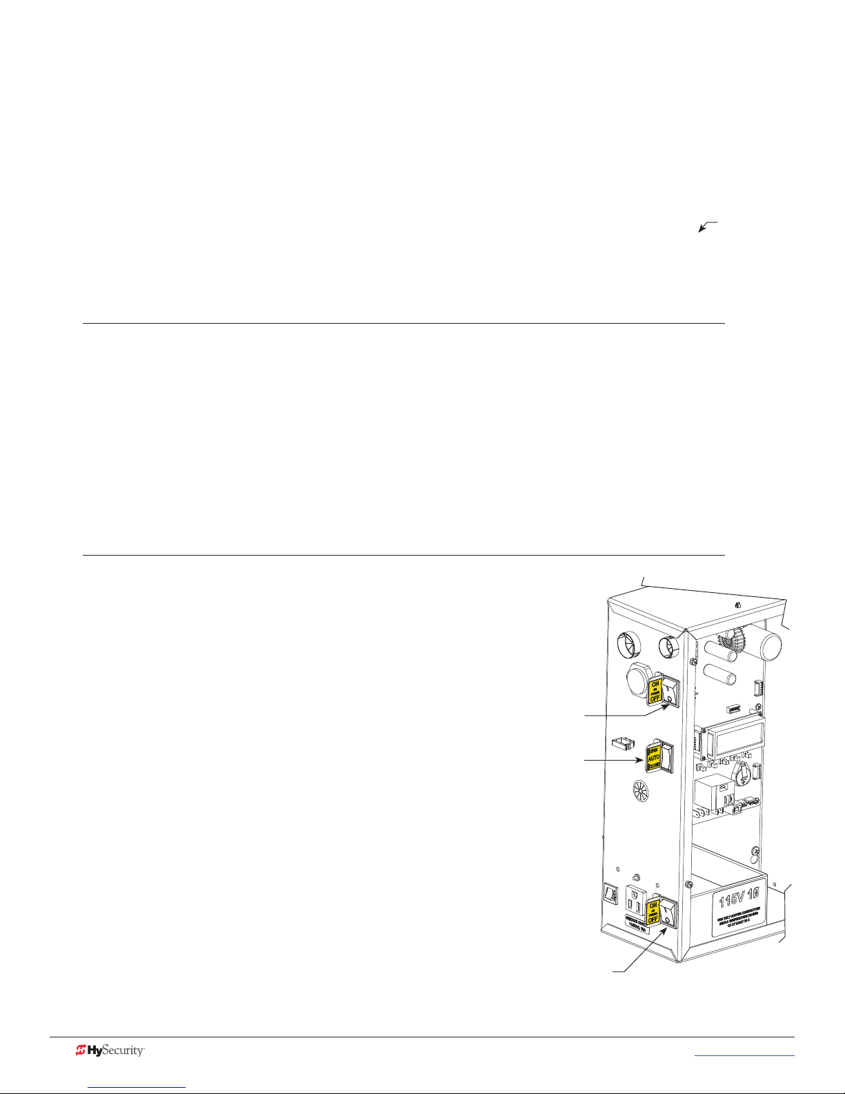
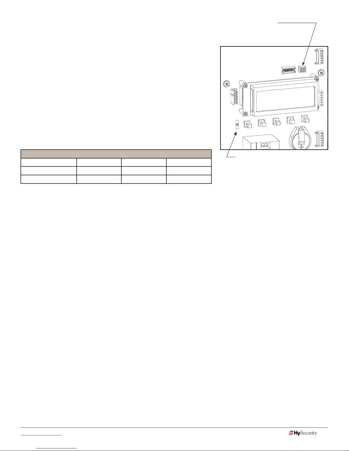
After GATE OPEN appears on the
display, turn the DC power switch OFF.
DC power switch
Connect the red battery wire.
(Refer to step 4 in the Installation
Make sure AC and DC power switches
are in the OFF position.
Instructions.)
Press the DC switch ON and toggle
HOLD switch to Hold Open.
Display
HOLD
toggle
switch
AC power
switch
Front access
panel
Spline collar
bolt & nut
Position Breakaway Arm
Slide the clamp onto the drive
Bracket so the clamp
opening faces up.
NOTE: You may need to loosen the collar bolt & nut to
shaft. Align gear teeth as you
slide clamp against chassis.
NOTE: Follow the video to feed wire harness through chassis,
assemble barrier arm, connect lighting and program the gate operator.
Secure clamp to drive shaft
using the fasteners provided.
position the clamp. Re-tighten when spline properly set .
• Utility knife
• Standard socket set
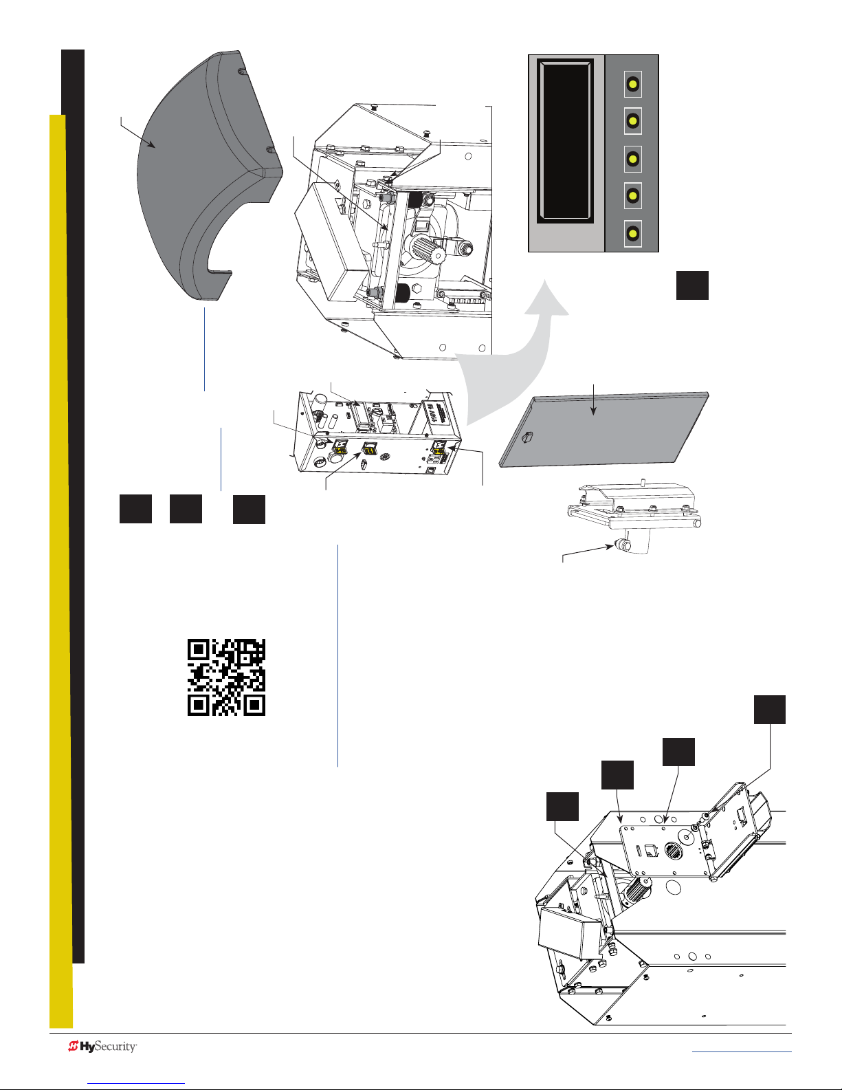
StrongArmPark DC Breakaway Arm
Bracket Installation
ii MX3650-01 Rev. D StrongArmPark DC Programming & Operations © 2017 www.hysecurity.com
Tools Required
Remove Physical Stop
Bracket (4 fasteners)
(5:50 min)
• Standard hex key set
To review the installation video, scan the QR code with your cell phone
or click on the Youtube video location: https://youtu.be/AdTWNYcC-NU
1. Install the breakaway arm bracket
2. Connect the magnetic kill switch
3. Connect the arm lighting and feed wire through the chassis to the controller
4. Program the controller, Installer Menu setting “BA” Breakaway switch.
In a short 8 minutes, the installation video shows you how to:
To install the breakaway arm bracket onto the StrongArmPark DC, you
can take the steps shown here and view the video for additional step
clarication.
Page 3
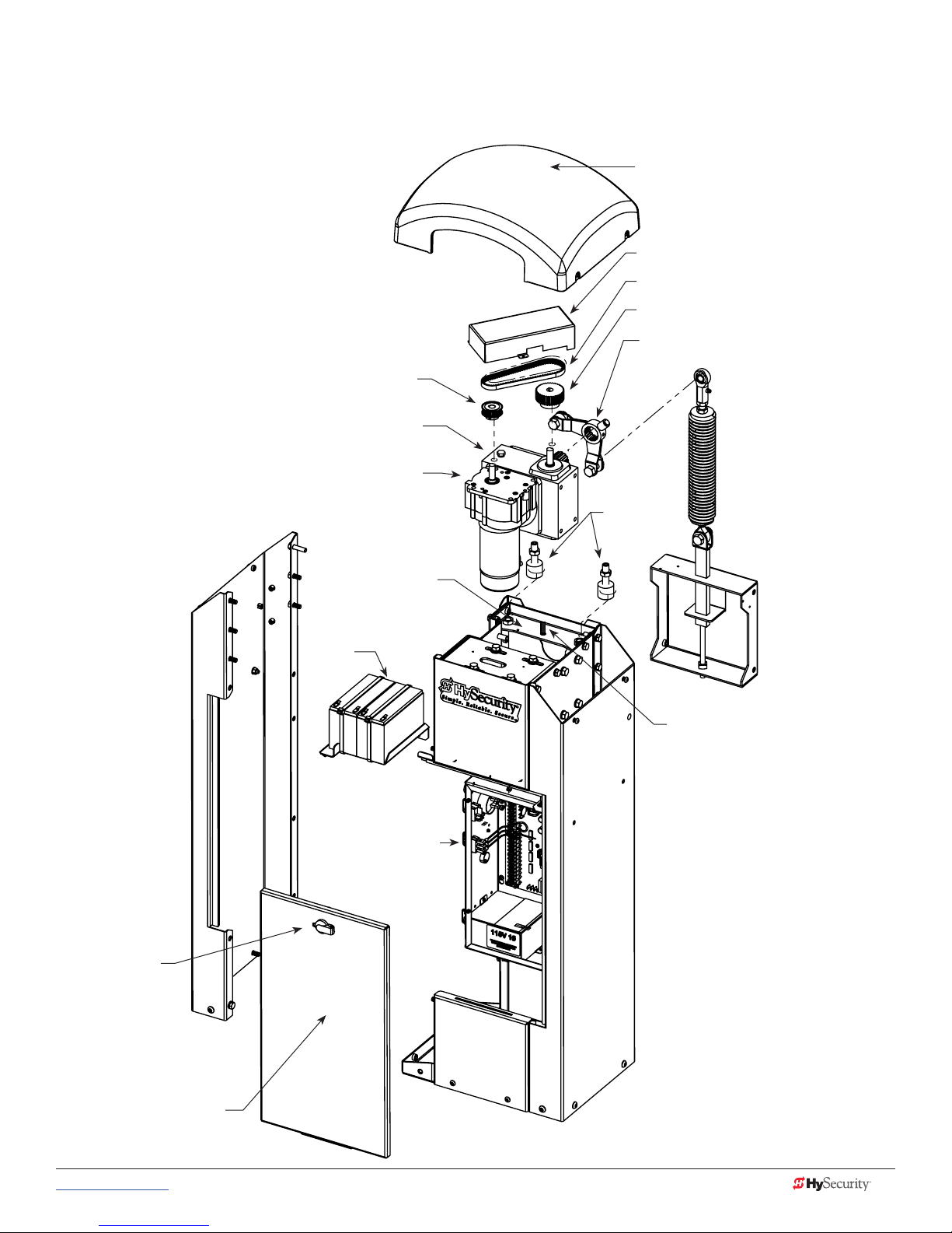
StrongArmPark DC Components:
Arm Chassis
Cover, Top Cap
Cover, Drive Belt
Belt, Drive
Pulley, Gearbox
Lever, Physical Stop
Assembly
Pulley, Motor
Gearbox
Motor, Gearbox
Bracket, Physical Stop
12V Battery Kit,
8Ah
Electrical,
Control Box
Spring Assist Assembly
(StrongArmPark DC 14)
Bumper
Replacement
Kit
Target Sensor Switch
DO NOT MOVE the
target sensor.
Lock,
Latch with Key
Panel,
Front Access
www.hysecurity.com © 2017 Introduction MX3650-01 Rev. D iii
Page 4
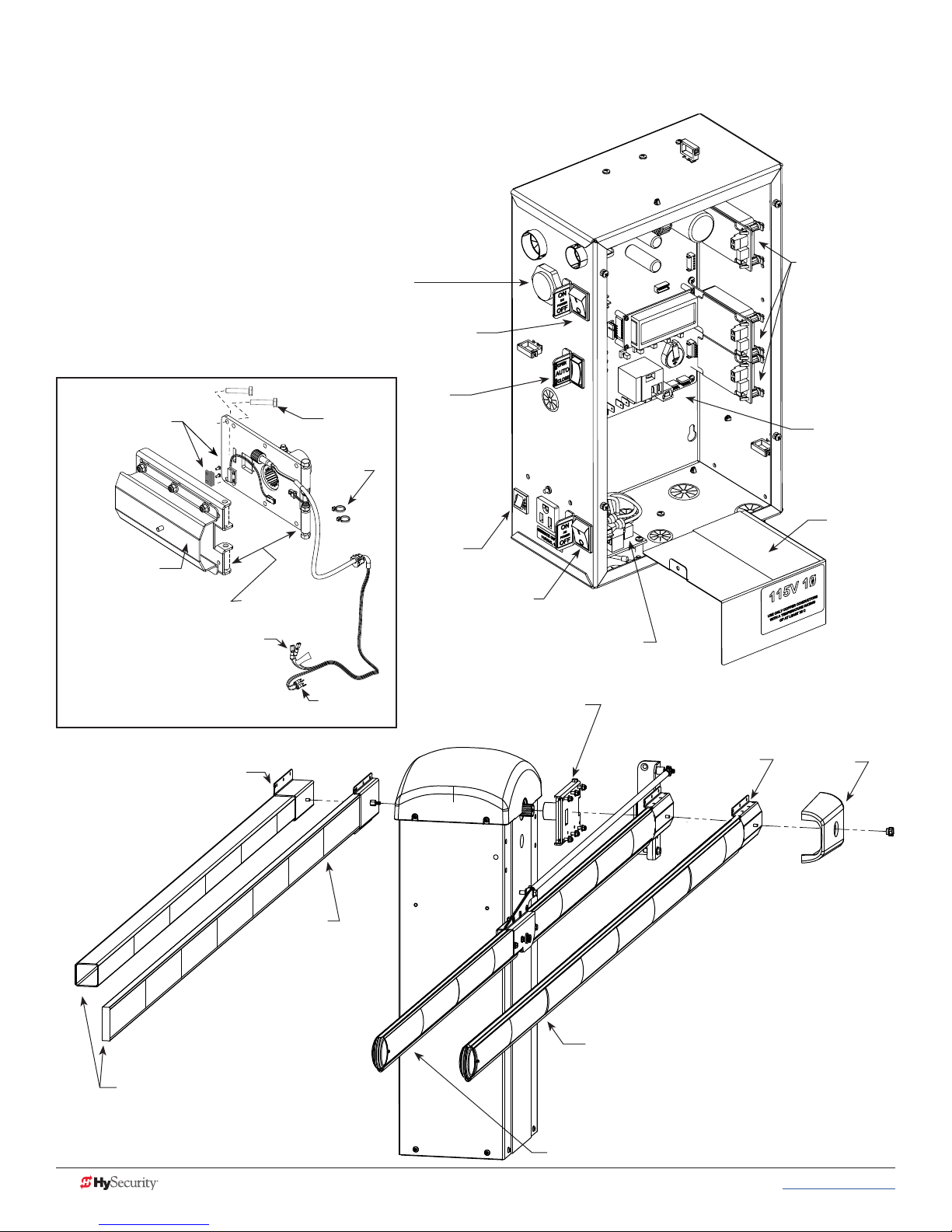
StrongArmPark DC Components: Control Box
and Arm Configurations
Detector, Hy5x
Buzzer
DC switch On/Off
Factory installed
magnet (kill switch)
MX3764 & MX3763
Breakaway
bracket
MX3680
Connections to Controller
Female Quick Connects:
User2 Relay (NO) & +24VDC
Spade connections:
COM & SENSOR 3
Exploded View MX4050 Kit
Bracket, 2.5-inch Square PVC
Breakaway
fasteners
Shown separated
for reference only
+24V
Spade
connections
Wire
ties
Switch,
Hold Open/Close
Circuit
breaker
AC switch
On/Off
Board, Power supply
Bracket,
Breakaway
and
Hardware
Barrier Arms and
Mounting Brackets
Attachment
plate
Board,
Smart DC
Controller
High
Voltage
Cover
End cap
Bracket,
Wood
Barrier Arms not supplied by
HySecurity
iv MX3650-01 Rev. D StrongArmPark DC Programming & Operations © 2017 www.hysecurity.com
Arm, Replacement, Aluminum
Arm, Replacement, Articulating
Page 5

StrongArmPark DC Installer CheckList
The following list provides a high level overview of the tasks involved in installing the StrongArmPark DC gate
operator. Take a moment to review the list and check off the items as you complete the install.
Site Prep - concrete pad location/dimensions. Use template printed on the side of the sipping box.
Make sure gate installation complies with ASTM F2200 Standard Specication for Automated Vehicular
Gate Construction. And, install the supplied WARNING signs on both sides of the barrier arm and on
its chassis. Signs must be viewable by incoming and outgoing vehicular trafc.
Check for compliance with local codes, site conditions, and NEC standards.
Install gate operator - (on concrete pad use four ½ - 13 x 3.5in long concrete wedge anchors.)
Connect AC Power.
Connect red wire to DC Power Switch.
Turn DC Power ON.
Connect all accessory devices.
Check the Smart DC Controller software version. If necessary, upload the latest version from
www.hysecurity.com. See Smart Touch Analyze and Retrieve Tool.
Set the Close Timer (through the User Menu).
Set barrier arm speed, if applicable (through Installer Menu). Refer to S.T.A.R.T. (Smart Touch Analyze
and Retrieve Tool) in the Reference section.
Set the dynamic reversing sensitivity, if needed (through Installer Menu).
Set Relay User 2 to 28 or 29 and BA to 1 (breakaway arm) in the Installer Menu.
Congure changes through the Installer Menu depending on the accessory devices that you have
installed.
Give a copy of the Important Safety Information and pertinent operator instructions to the end user.
Show the end user how to:
• Remove the barrier arm from the breakaway bracket.
• Turn the power off and on to demonstrate learn limits after DC/AC cycles.
• Adjust physical limit stops for barrier arm open and close positioning.
• Turn the DC power switch off, which disengages the motor, and manually lift the barrier arm open.
Take photographs of the completed installation site and save it in your business les.
www.hysecurity.com © 2017 Introduction MX3650-01 Rev. D v
Page 6

Page intentionally left blank
vi MX3650-01 Rev. D StrongArmPark DC Programming & Operations © 2017 www.hysecurity.com
Page 7

Contents
StrongArmPArk DC BreAkAwAy Arm BrACket InStAllAtIon ......................................... II
StrongArmPark DC Components: Arm Chassis .............................................................................................................. iii
StrongArmPark DC Components: Control Box and Arm Congurations .......................................................................iv
Exploded View MX4050 Kit ......................................................................................................................................... iv
StrongArmPark DC Installer CheckList ............................................................................................................................. v
welCome to HySeCurIty ...........................................................................................1
Contact Information .........................................................................................................................................................1
Notices and Bulletins .......................................................................................................................................................2
Supplemental Documents ................................................................................................................................................2
Hazardous Materials and Proper Disposal .......................................................................................................................2
SAVE THESE INSTRUCTIONS .......................................................................................................................................4
Safety - Additional Installer Responsibility ....................................................................................................................4
Safety - Owner/User Responsibility ...............................................................................................................................6
Identifying Gate Operator Category and Usage Class ....................................................................................................7
HySecurity Gate Operators: UL 325 – 2016 .....................................................................................................................8
Table 1: HySecurity Gate Operators requiring External Monitored Entrapment Protection Sensors ...........................8
Table 2: HySecurity Gate Operators maintaining Object Detection .............................................................................8
External Entrapment Protection Sensors monitored by HySecurity Gate Operators ...................................................9
Wind Load Factors & Site Prep ......................................................................................................................................10
Manual Release ..............................................................................................................................................................10
Breakaway Arm Feature ................................................................................................................................................11
Dynamic Reversing Sensor .............................................................................................................................................11
Safety Notices ................................................................................................................................................................12
Common Industrial Symbols ..........................................................................................................................................12
Power ..................................................................................................................13
Installing the Earth Ground ............................................................................................................................................13
Wiring AC Power ............................................................................................................................................................14
Wiring 115VAC Power ...............................................................................................................................................15
Wiring 208/230VAC Power .........................................................................................................................................16
Connecting DC Power ...............................................................................................................................................17
Turning the Power Switch ON .....................................................................................................................................17
DISPlAy & menu oPtIonS ........................................................................................19
Initial Setup ...................................................................................................................................................................19
Understanding the Display and Keypad ........................................................................................................................19
Menu Mode ....................................................................................................................................................................20
Menu Mode Navigation .................................................................................................................................................20
www.hysecurity.com © 2017 Tabnle Contents MX3650-01 Rev. D vii
Page 8

Smart DC Controller: Menu Mode Navigation Buttons ..............................................................................................20
Run Mode .....................................................................................................................................................................21
Viewing Operator Status Displays ..................................................................................................................................21
Example of Operator Status Displays .........................................................................................................................21
User Menu ......................................................................................................................................................................22
Table 3: User Menu .....................................................................................................................................................22
Installer Menu .................................................................................................................................................................24
Table 4: Installer Menu ................................................................................................................................................25
Setting the Time and Date .............................................................................................................................................30
Resetting Open and Close Limits ..................................................................................................................................30
Learn Open Limits .......................................................................................................................................................31
Learn Close Limits .......................................................................................................................................................31
Test the Operator ...........................................................................................................................................................31
Setting the Close Timer .................................................................................................................................................32
SDC InPutS & wIrIng ............................................................................................33
Overview of the Smart DC Controller ............................................................................................................................34
Integrating with Security Systems ..................................................................................................................................35
Smart DC Controller Inputs ............................................................................................................................................36
SDC Terminal Inputs .......................................................................................................................................................36
Table 5: SDC Inputs ....................................................................................................................................................36
SDC Inputs ..................................................................................................................................................................37
Connecting Accessory Devices ......................................................................................................................................38
User Relays - Programming Procedure ...........................................................................................................................39
Table 6: Programmable User Relays............................................................................................................................39
Revenue Control Parking Applications ...........................................................................................................................41
Table 7: Programmable User Relays, Revenue Control ...............................................................................................41
Extended Relay Module Option ...................................................................................................................................42
VeHICle DeteCtor InStAllAtIon AnD looP lAyoutS .....................................................43
Anti-TailGate Mode (Closing Logic) ............................................................................................................................43
TailGate Alert .............................................................................................................................................................43
Vehicle Detectors and the Smart DC Controller ............................................................................................................44
Hy5B Installation ........................................................................................................................................................44
Test the Vehicle Loop ..................................................................................................................................................45
Check the Version of Software ....................................................................................................................................45
Install Hy5B Vehicle Detectors ....................................................................................................................................46
Installing Standard 11-Pin Box Type Vehicle Detectors ..................................................................................................48
StrongArmPark DC Center Loop Layout ........................................................................................................................49
StrongArmPark DC Center Loop Conguration .............................................................................................................50
Sequenced Gates #1: Loop Layout ................................................................................................................................51
StrongArmPark DC Loop Layout .................................................................................................................................51
Sequenced Gates #2: Loop Layout ................................................................................................................................52
StrongArmPark DC Loop Layout .................................................................................................................................52
viii MX3650-01 Rev. D StrongArmPark DC Programming & Operations © 2017 www.hysecurity.com
Page 9

PHoto eye InStAllAtIon ..........................................................................................53
Photo Eyes (Non-Contact) Installation ...........................................................................................................................54
Compatibility ..............................................................................................................................................................54
Installation ...................................................................................................................................................................54
Conguration ..............................................................................................................................................................55
Photo Eye Connections: Smart Touch & Smart DC Controllers ..................................................................................55
Photo Eye Function .....................................................................................................................................................55
Retro-Reective Photo Eye Systems ..............................................................................................................................56
Photo Eye Alignment Feature .......................................................................................................................................57
Smart DC Controller: Menu Mode Navigation Buttons ..............................................................................................57
trouBleSHootIng ...................................................................................................59
System Diagnostic Messages .........................................................................................................................................59
Table 8: Troubleshooting Codes .................................................................................................................................60
Adjusting the Dynamic Reversing Sensor ......................................................................................................................66
Conditions Affecting the Dynamic Reversing Sensor .....................................................................................................67
Access the Event Log through the User Menu ..............................................................................................................67
StrongArmPark DC Wiring Schematics ..........................................................................................................................68
StrongArmPark DC 10 and StrongArmPark DC 14 Schematics ..................................................................................68
StrongArmPark DC Wiring Schematics - Solar ...............................................................................................................69
StrongArmPark DCS 10 Solar and StrongArmPark DCS 14 Solar Schematics ............................................................69
generAl mAIntenAnCe ...........................................................................................71
Smart Touch Analyze and Retrieve Tool (S.T.A.R.T.) ......................................................................................................71
What You Need ..........................................................................................................................................................71
Installing S.T.A.R.T. Software .......................................................................................................................................71
Software Maintenance ....................................................................................................................................................72
Electrical Controls ..........................................................................................................................................................72
Clock Battery Replacement .........................................................................................................................................72
Fuse Replacement ......................................................................................................................................................72
Mechanical Maintenance ...............................................................................................................................................73
HyProtect™ Breakaway Arm Mount ...........................................................................................................................73
Breakaway Fasteners ...................................................................................................................................................73
Drive Belt Tension and Alignment ..................................................................................................................................74
DC Battery Replacement ................................................................................................................................................75
referenCe .............................................................................................................77
Handing Change ............................................................................................................................................................77
Spring & Physical Stop Lever Assembly .........................................................................................................................78
Set Handing ................................................................................................................................................................78
Installation Instructions
MX4010 ..........................................................................................................................................................................79
StrongArmPark DC Articulating Arm ..........................................................................................................................79
Assemble the Pivot Block and Connect Light Strings .................................................................................................80
Feeding the cable (LED lighting) through the Pivot Block ..........................................................................................80
www.hysecurity.com © 2017 Tabnle Contents MX3650-01 Rev. D ix
Page 10

StrongArmPArk DC: ArtICulAtIng Arm ASSemBly ....................................................81
Remove Plugs in Chassis .............................................................................................................................................81
Assemble Arm onto chassis ........................................................................................................................................81
Feed Cable through Chassis .......................................................................................................................................81
Fasten Articulating Arm Bracket to Rod End and attach assembly to Chassis ...........................................................81
StrongArmPark DC: Lighting Connection ...................................................................................................................82
Smart DC Controller: Menu Mode Navigation Buttons ..............................................................................................82
Connect Arm Light Cables ..........................................................................................................................................82
Turn OFF AC and DC power .......................................................................................................................................82
Arm Lights and Breakaway Switch Connections on Smart DC Controller .................................................................83
Retrot Requires Hole Drilled in Chassis ....................................................................................................................83
StrongArmPark DC Breakaway Arm Bracket Installation ................................................................................................84
WARRANTY ....................................................................................................................................................................85
Specications .................................................................................................................................................................86
x MX3650-01 Rev. D StrongArmPark DC Programming & Operations © 2017 www.hysecurity.com
Page 11
Welcome to HySecurity
Thank you for purchasing our premium StrongArmPark DC™ Gate Operator. At HySecurity Gate, Inc., we pride
ourselves on quality.
All operator designs are tested for hundreds of thousands of cycles before being released to the market. Trafc
barrier, slide, swing, fortied crash barrier gate and vertical lift operators have all received rigorous testing and
certication. Security, low maintenance, exible conguration, and overall toughness are the foremost criteria
for all HySecurity products.
Our commitment to quality and innovation will become evident as the features and performance of the
expertly engineered and manufactured StrongArmPark DC become familiar to you. Thank you again for the
condence you’ve shown in becoming part of the HySecurity family and in choosing a premium industry-
leading product.
ContaCt InformatIon
Qualied HySecurity distributors are experienced and trained to assist in resolving any problems. For the name
of a qualied distributor near you, call HySecurity at 800-321-9947.
Before contacting your distributor or HySecurity Technical Support, obtain the serial number of your operator.
For information about HySecurity training for installers, maintenance personnel, and end users, refer to the
company website at www.hysecurity.com.
www.hysecurity.com © 2017 Safety MX3650-01 Rev. D 1
HySecurity Gate, Inc. Headquarters in Kent, WA
Page 12

notICes and BulletIns
Installers should visit HySecurity’s online Technical Support page at www.hysecurity.com or contact HySecurity
prior to installing product to make sure they have received the most up-to-date information.
supplemental doCuments
The product literature is comprehensive and contains information needed to plan, install, operate and maintain
your gate operator. Additional general information concerning HySecurity gate operators can be obtained
from the following:
• HySecurity web site www.hysecurity.com - Contains links to the product catalog, product order
form, operator manuals, operator software downloads, technical support bulletins and other useful
information.
• S.T.A.R.T. - Smart Touch Analyze and Retrieve Tool - User’s Guide (D0049) detailing the extensive
software, diagnostic and troubleshooting capabilities of the Smart DC Controller board.
• Technical Bulletins (as applicable).
NOTE: Technical Bulletins are automatically issued to registered users of HySecurity products. The product warranty registration
card can be lled out online at www.hysecurity.com.
Hazardous materIals and proper dIsposal
Be aware of the international, federal, and local codes in your area and how best to handle hazardous waste
materials.
The pump pack uid, found in all hydraulic HySecurity operators, can be recycled. Gear oil, found in HySecurity
electromechanical gate operators, can also be recycled. If the uids are mixed or contaminated with any
solvents or other chemicals, they become hazardous waste. Hazardous waste requirements for storage and
disposal must be followed.
CAUTION
If the gate operator has a battery backup system, the batteries contain materials that are considered hazardous
to the environment. Proper disposal of the battery is required by federal law. In the U.S.A., refer to federal EPA
guidelines for proper hazardous waste disposal.
2 MX3650-01 Rev. D StrongArmPark DC Programming & Operations © 2017 www.hysecurity.com
Page 13
Important safetY InformatIon
WARNING
WARNING
Read all the product safety information prior to installation. Automatic gate operators move the gate with high
force and can cause serious injury and death! Make sure the automatic gate operator is installed to reduce the
risks of entrapment. Verify the gate operator is installed to comply with all safety standards and local and federal
regulations.
Understand that you as the site designer, installer, maintenance crew, or owner/user must consider the
risks associated with gate operators. Be sure to take responsibility, read, and follow the Important Safety
Information in this manual and review all the literature that accompanies the product.
Hazards, associated with automatic gates, can be reduced with proper site design, installation, and use.
Installers, maintenance crews, and owners/users must read and follow the safety requirements found in the
HySecurity product manuals.
It is important that only qualied installers handle the installation of the HySecurity equipment and gate
operator. A “qualied” installer has one of the following:
• A minimum of three years experience installing similar equipment
• Proof of attending a HySecurity Technical Training seminar within the past three years
• Signicant manufacturer endorsements of technical aptitude in gate operator installation and
operation
Underwriter Laboratories (UL) and the American Society for Testing and Materials (ASTM) are responsible for
current safety standards and regulations regarding automatic vehicular gate operators. To pass certication, all
aspects of gate operator and gate installation must comply with the appropriate safety standards.
For the most up-to-date ASTM F2200 Gate and Fence Standards, refer to www.astm.org.
For UL 325 Safety Standards, refer to www.ul.com.
A moving gate or barrier arm, bollard, or wedge can cause serious injury or death. In the following safety
information, the term “gate” refers to the hardware that the automatic gate operator is moving: gate, barrier
arm, bollard, or wedge.
www.hysecurity.com © 2017 Safety MX3650-01 Rev. D 3
SAVE THESE INSTRUCTIONS
Page 14

Important safetY InformatIon
To reduce the risk of injury or death:
1. READ AND FOLLOW ALL INSTRUCTIONS. Read the gate operator’s product manual and review all the product
labels and literature prior to installing, operating, or maintaining the automatic gate operator.
2. Never let children operate or play with gate controls. Keep all remote controls, especially radio transmitters, away
from children. Do not allow children to play on or around the gate or gate operators.
3. Always keep people and objects away from the gate. NO ONE SHOULD CROSS THE PATH OF THE MOVING
GATE. Start the gate operator only when a gate’s travel path is clear.
4. Test the gate operator monthly. The gate MUST reverse on contact with a rigid object or stop when an object
activates the non-contact sensors. After adjusting the force or the limit of travel, retest the gate operator. Perform
routine tests of the entrapment protection sensors, such as photo eyes and gate edges. Failure to adjust and
retest the gate operator properly can increase the risk of injury or death.
5. Use the emergency release only when the gate is not moving.
6. KEEP GATES PROPERLY MAINTAINED. Read the product manuals. Have a qualied service person make repairs
to gate hardware and replace batteries in accessory or entrapment sensory devices on a regular basis.
7. The automated gate entry is for vehicle use only. Pedestrians must use a separate entrance. Make sure a separate
walk-through entrance is nearby. Make certain a clear pedestrian path is designated and signs direct pedestrians
to the walk-through gate.
8. Install the supplied WARNING signs on the inside and outside of the gate or barrier gate/operator so they are
clearly visible from both the secure and public sides. Installing the signs is a requirement for UL 325 compliance.
9. Use monitored sensors for protection against entrapment as specied in the current UL 325 Standard of Safety.
Safety - Additional Installer Responsibility
• Verify the gate operator usage class for the site. For all gate operators other than Crash-rated, refer to Identifying
Gate Operator Category and Usage Class in the product manual. Install the operator only when the gate
operator class is correct for the site, size, and type of gate.
• The gate operator must be properly grounded and the incoming power voltage must match the voltage label on
the junction box.
• Install an automatic operator only on gates that comply with ASTM F2200 Gate and Fence Standards. Screen or
enclose openings in the gate per UL 325 Safety Standards which include:
• All horizontal slide gates must guard or screen openings from the gate’s base support to a minimum height of
6 feet (183 cm) above the ground. This must prevent a sphere of 2¼-inches (57mm) in diameter from passing
through an opening in the gate or the adjacent fence that is covered in the gate’s open position.
• Physical stops must exist in the gate construction to prevent over-travel in both directions and, for slide gates,
guard posts must be installed to prevent the gate from falling in the event of a roller failure.
• Before attaching the operator to the gate, move the gate or barrier gate in both directions. Make sure it is level
and moves freely. A gate or barrier gate that moves easily reduces strain on operator components. Gravity should
play no part in the opening or closing of a slide gate.
• Never over-tighten a clutch or pressure relief valve to compensate for a stiff or damaged gate.
• Make sure all exposed pinch points, rollers and wheels are guarded.
• Reduce the risk of entrapment throughout the entire travel path by making sure the gate is installed in a location
which ensures the required clearance between the gate and adjacent structures when opening or closing. On
slide gates, minimize the parallel gap between the gate and the fence.
4 MX3650-01 Rev. D StrongArmPark DC Programming & Operations © 2017 www.hysecurity.com
SAVE THESE INSTRUCTIONS
Page 15

• Install the gate operator on the secure (non-public) side of the gate. Note that swing gates cannot open into
public areas.
• Install external entrapment protection sensors so pedestrians are protected from entrapment in both directions
of gate travel and all hazard areas are fully protected. On hydraulic gates, set the pressure relief valve at the
lowest allowable setting that will reliably operate the gate. The pressure relief valve controls the applied force of
the operator and the sensitivity of the inherent entrapment sensor (IES). Note that no IES exists in the StrongArm
operator or Crash products.
• Never disable the Warn Before Operate buzzer. This buzzer provides an alert that the gate is about to move.
• Mount access control devices beyond reach of the gate. The control devices that operate the gate must:
• Be located in a clear line of sight to the gate. Locate controls (Open, Close, Stop/Reset) where a user will
have a clear view of the gate.
• Be mounted beyond 6 feet (183 cm) of the gate, to prevent users from touching or accessing the gate while
operating the controls. People attempting to access the controls by reaching through or around the gate can
be seriously injured or killed by the moving gate.
• Incorporate a security feature to prevent unauthorized use.
• Connect radio and other remote access (non-resetting controls) to the RADIO OPTIONS terminal.
• Open and close the gate to conrm that it was properly installed and to ensure reduced risk of entrapment.
Verify the clearance between the gate and adjacent structures per UL 325 Safety Standards. Have a qualied
technician test the gate monthly.
• When you complete the installation, demonstrate the safety features and operation of the gate operator to the
end user:
• Clearly explain and demonstrate the consequences of removing or defeating any of the safety features.
• Remove the operator cover(s), and then turn the power on and off.
• Manually release the gate. (Manually release only when the gate is NOT moving.)
• Use the Emergency Stop Button. (If an emergency stop button is not available, show the user where the Stop
button is located on the gate operator.)
NOTE: Gate operator instructions must be given to the owner per UL 325 Safety Standards.
• Take photographs of the completed installation site and save it in your business les.
www.hysecurity.com © 2017 Safety MX3650-01 Rev. D 5
SAVE THESE INSTRUCTIONS
Page 16
Important safetY InformatIon
Safety - Owner/User Responsibility
As the owner/user, you are responsible for the correct and safe installation, operation and maintenance of
the StrongArmPark DC gate operator. It is of the utmost importance that you read and follow the specic
instructions and precautions found in the Important Safety Information addressed in this manual. In addition,
you must adhere to the safety standards of applicable federal, state, and local safety regulations, industry
standards, and/or procedures.
NOTICE: For installations outside the United States, make sure that you follow the applicable international,
regional, and local safety standards.
• Automatic gates are for vehicular use only; provide and maintain walkways and signs to direct
pedestrians to a separate walk-through entrance.
• An automatic gate can start at any time without warning; always keep people away from the gate area.
• Never let children operate or play with gate controls. Keep all remote controls, especially radio
transmitters, away from children. Do not allow children to play on or around the barrier arm, gate area,
or gate operators.
• Learn how to turn the power on and off. Learn how to manually operate the barrier arm.
• WARNING signs supplied with the gate operator must remain installed and clearly visible on both
sides of the gate. The signs are required to maintain UL 325 compliance.
• Do not physically disable the warning buzzer and NEVER
disconnect or cut its wires. The buzzer provides compliance
with the Manual on Uniform Trafc Control Devices (MUTCD)
standards. Disabling the warning buzzer may increase the risk of
death or serious injury.
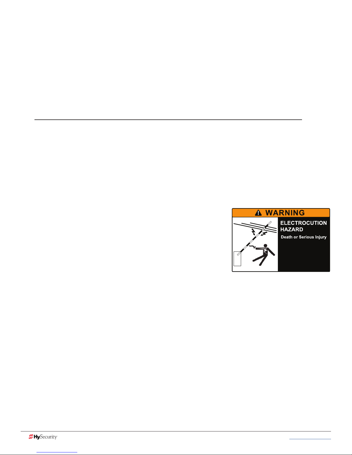
• Be aware of the length of the barrier arm. Safeguard against any
possible contact between the barrier arm and overhead power or
utility cables and wires.
Be aware of the barrier arm length.
To reduce the risk of electrocution,
maintain a minimum 10 foot (3 m)
clearance between the barrier arm
and all electrical utility lines and
equipment.
• Do not remove entrapment devices or any other safety features.
• Have a professional gate installer routinely inspect the gate hardware and test the entrapment
protection sensors and overall gate operation. Have a qualied service person make repairs to gate
hardware and equipment to keep the gate running smoothly.
6 MX3650-01 Rev. D StrongArmPark DC Programming & Operations © 2017 www.hysecurity.com
SAVE THESE INSTRUCTIONS
Page 17
IdentIfYIng gate operator CategorY and usage Class
Gate operators are given a usage class according to UL 325 Standard of Safety. The usage class is determined
by the area that the vehicular gate operator services.
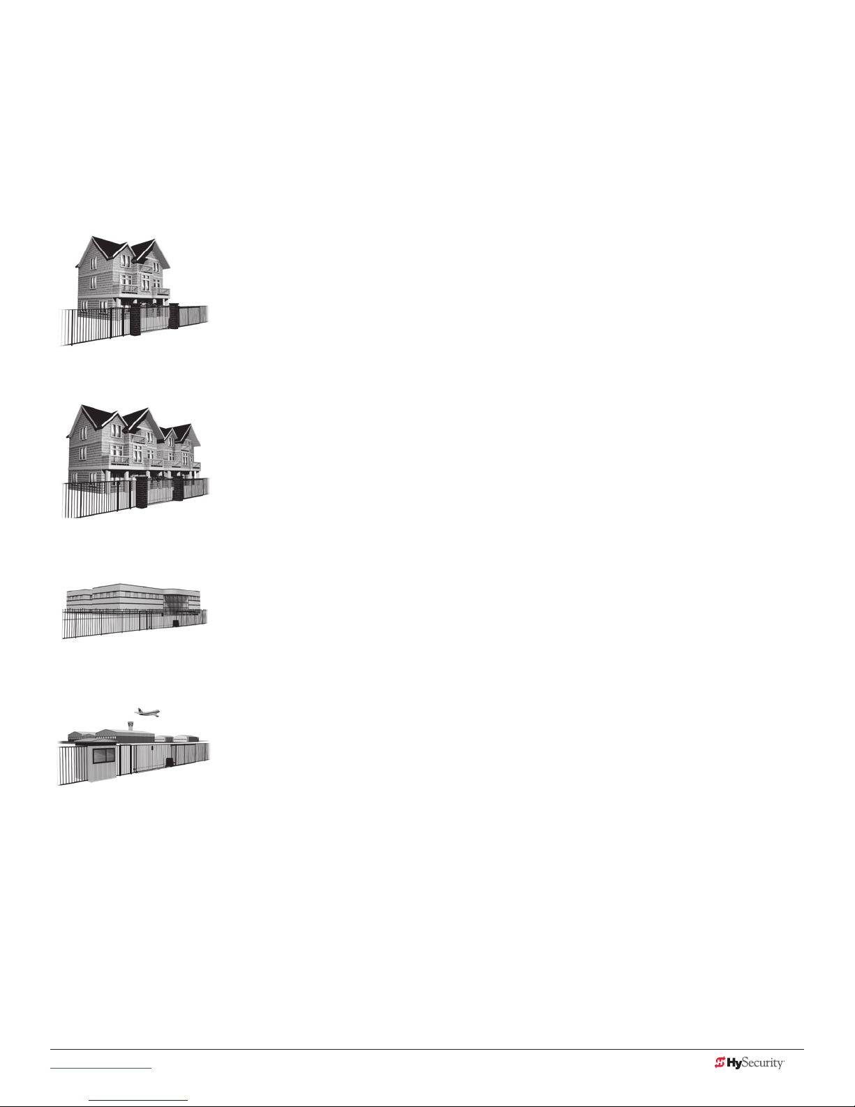
Four different vehicular usage classes are dened by UL 325:
Class I
Class I: Intended for use in garages or parking areas associated with a residence
of one to four single families.
Class II
Class II: Intended for use in a commercial location or building such as a multifamily housing unit (ve or more single family units) hotels, garages, retail stores
or other buildings accessible by or servicing the general public.
Class III
Class IV
Class III: Intended for use in an industrial location or building such as a factory
or loading dock area or other locations NOT accessible by or intended to
service the general public.
Class IV: Intended for use in a guarded industrial location or building such as
an airport security area or other restricted access locations, NOT servicing the
general public, in which unauthorized access is prevented via supervision by
security personnel.
www.hysecurity.com © 2017 Safety MX3650-01 Rev. D 7
SAVE THESE INSTRUCTIONS
Page 18

HYseCurItY gate operators: ul 325 – 2016
The following bullet points highlight how your automated gate system sites can monitor external entrapment
protection using HySecurity gate operators:
• Normally Closed (NC) sensors – Before gate movement occurs, the gate operator veries that the
external entrapment protection sensor is connected and fully functional.
• Build Year (BY) – An added menu item distinguishes between pre-2016 manufacturing dates and
UL 325 - 2016 manufacturing dates. Build Year (BY) is a factory-setting. Build Year 2 (BY 2) is the default for
all HySecurity gate operators indicating a manufacturing date of 2016 in the serial number. Replacement
controller boards for existing sites allow for a Build Year setting of 1 (BY 1) (pre-2016).
• Independent Sensor Inputs – The edge, photo eye and photo eye COM inputs on the Smart Touch and
Smart DC Controllers (STC and SDC) have been re-labeled. The same wiring connections become three
independent methods for easy entrapment protection sensor conguration and normally closed outputs.
Table 1: HySecurity Gate Operators requiring External Monitored Entrapment
Protection Sensors
UL 325 Entrapment Protection Sensor Monitoring Required
HySecurity Gate Operators
(includes Modular, Correctional, and
UPS models)
Build Year
UL 325 - 2016
(set at the factory)
Normally Closed (NC) sensors tested & approved.
Three SENSOR Inputs on Controller.
Installer Menu congurable.
Build Year (BY) factory-set to UL 325 - 2016.
SlideDriver 15, 40, 30F, 50VF 2/3, 80, 200 2
SlideDriver 50VF series 2
SlideSmart DC 15 & DCS 15 2
SlideSmart DC 10F & DCS 10F 2
SwingRiser 14, 14-Twin, 19,
19-Twin, 30, 30-Twin
SwingSmart DC 20 & DCS 20 2
HydraSwing 40, 40F, 40-Twin, 40F-Twin,
80F, 150
HydraLift 10, 10F, 20, 20F 2
2
2
●
●
●
●
●
●
●
●
Table 2: HySecurity Gate Operators maintaining Object Detection
Table 2 indicates those HySecurity gate operators that may be within the exception parameters of UL 325 or
comply with standards other than UL 325, but continue to maintain object detection capabilities. HySecurity
strongly recommends that you assess every site for entrapment zones and provide the necessary protection to
guard against entrapment.
HySecurity Gate Operator's with
Obstruction Protection (Object Detection)
StrongArm (HTG) 14, 20, 28, 36 2
StrongArmCRASH (M30/M50) 2
StrongArmPark DC 10 & DCS 10
StrongArmPark DC 14 & DCS 14
WedgeSmart DC 10 & 10 DCS 2
WedgeSmart DC 14 & 14 DCS 2
HydraWedge SM50 2
Build Year
UL 325 - 2016
2
Sensor Inputs automatically set to "NOT USED"
Installer has option to change settings as site design dictates.
●
●
●
●
●
●
8 MX3650-01 Rev. D StrongArmPark DC Programming & Operations © 2017 www.hysecurity.com
Page 19

External Entrapment Protection Sensors monitored by HySecurity Gate Operators
Any external entrapment protection sensor may be monitored by HySecurity gate operators, provided the
following requirements are met:
• Sensor is marked as certied to UL 325 Standard of Safety by a Nationally Recognized Test laboratory,
such as UL or ETL.
• If the sensor only has a normally open (NO) output with a 8.2KΩ or 10KΩ resistor, such as an edge
sensor, then a conversion device must be used to convert the NO resistor output to an NC output.
Example of two different installation methods:
• Method A - Wired
Connect the edge sensor to a NC conversion module (GEM-104 or GEM-204) and connect the
module to the operator controls according to the manufacturer’s instructions.
• Method B - Wireless
Connect the edge sensor to a UL 325 certied wireless edge transmitter and connect a matching
receiver to the operator controls according to the manufacturer’s instructions.
A resource list is available from the drop down Gate Safety menu on the HySecurity website. The HySecurity
recommended list shows examples of external entrapment protection sensors available for NC monitoring of
automatic gate operators. All HySecurity gate operators manufactured after January 1, 2016 using software
versions h4.50 or h5.50 (or later) comply with UL 325 Standard of Safety for monitoring entrapment protection
sensors using normally closed contacts.
The site designer or installer must determine which external entrapment protection sensors will be installed
with the gate operator to create a UL 325 compliant automatic gate operator site.
The UL 325 Standard of Safety and ASTM F2200 dene the MINIMUM gate site requirements. Gate site,
gate hardware, gate usage and other conditions may dictate the use of additional entrapment protection
sensors. It is up to the gate system designer and installer to assess appropriate gate safety design and install
the components required to protect all potential entrapment zones. Always check your local area codes and
comply with all standards and regulations.
CAUTION
Temperatures and environmental conditions affect proper operation of external entrapment protection sensors.
Always check the manufacturer’s specications shipped with the sensors. Consult the manufacturer’s instructions
for correct wiring connections, hardware installation and proper operation.
www.hysecurity.com © 2017 Safety MX3650-01 Rev. D 9
Page 20
WInd load faCtors & sIte prep
Wind load is always a factor when considering the appropriate gate for a particular site. Solid gate panels
produce a larger wind load than gates with slats or open decorative features. If you are installing a gate
operator in high wind areas, the gate design may affect the load on the gate operator. Because wind force acts
the same as an obstruction, it is important that gates be designed to present a relatively low surface area for
the wind to push on the gate panel.
In the case of the StrongArmPark DC, it is always advisable to remove the barrier arm altogether when high
winds are anticipated. Another option is to install a catch post to keep the barrier arm from bending in the
wind.
NOTICE: Under certain wind load conditions, damage to the barrier arm or gate operator may occur and is not
covered by the HySecurity Warranty.
StrongArmPark DC incorporates a dynamic reversing sensor into its design. More information about adjusting
the sensitivity can be found in this manual under, Adjusting the Dynamic Reversing Sensor on page 66.
When the barrier arm encounters an impediment, it sends a signal to the gate operator to stop and reverse
direction. This feature may be falsely triggered in excessively windy conditions.
manual release
NOTICE: Before attempting a manual release, make sure the barrier arm is not in motion.
Make sure and instruct all users how to move the gate
manually. Use the Hold Open toggle switch to raise the
barrier arm or, in the case of complete AC & DC power
loss, turn off both AC and DC power switches and lift the
barrier arm to open it.
DC switch On/Off
Switch, Hold Open/Close
10 MX3650-01 Rev. D StrongArmPark DC Programming & Operations © 2017 www.hysecurity.com
AC switch On/Off
Page 21

BreakaWaY arm feature
Every StrongArmPark DC operator comes equipped with a breakaway arm
bracket, which lessens damage to the operator and reduces the cost of arm
replacement due to vehicle hits.
For more information about installing the breakaway arm bracket, review the
StrongArmPark DC Installation Instructions.
Nylon bolts
with steel
nuts
dYnamIC reversIng sensor
The StrongArmPark DC provides an integral feature to help prevent entrapment. While closing, if the dynamic
reversing sensor is tripped twice within a specic period of time, it enters safe mode. The operator stops
barrier arm travel. For more information, see Adjusting the Dynamic Reversing Sensor on page 66.
www.hysecurity.com © 2017 Safety MX3650-01 Rev. D 11
Page 22
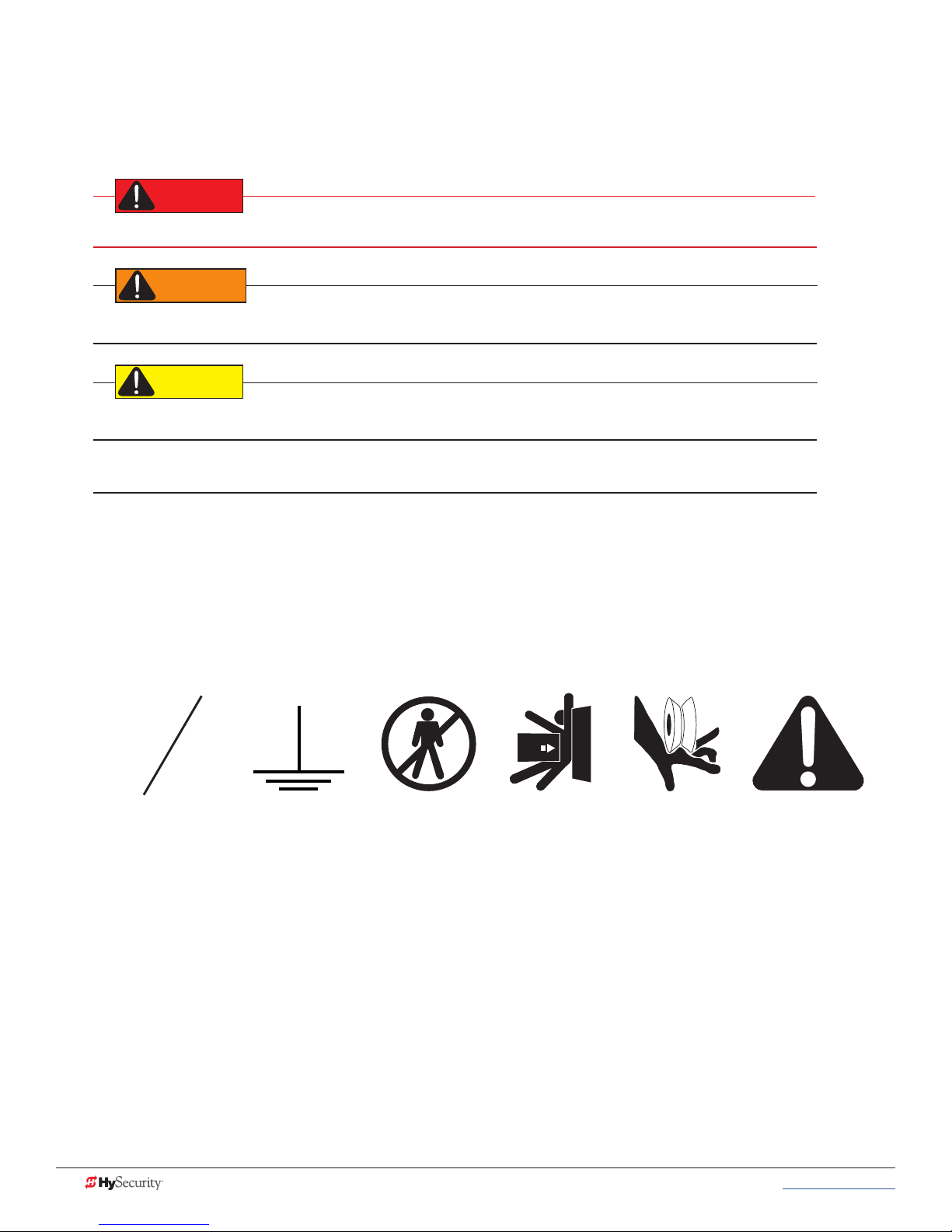
safetY notICes
DANGER
WARNING
CAUTION
The following four levels of safety notices are used where applicable within this manual; each notice contains
information specic to the situation.
Indicates death or serious injury will occur if the hazardous situation is not avoided.
Indicates death or serious injury could occur if the hazardous situation is not avoided.
Indicates mild or moderate injury could occur if the hazardous situation is not avoided.
NOTICE: Indicates damage to equipment is probable if the hazardous situation in not avoided.
Common IndustrIal sYmBols
The following international safety symbols may appear on the product or in its literature. The symbols are used
to alert you to potential personal injury hazards. Obey all safety messages that follow these symbols to avoid
possible injury or death.
O
Electrical Phase
Symbol
Ground
Symbol
- Danger -
Keep Away
Entrapment
Zone
Possible
Pinch Point
Attention
- Take Note -
12 MX3650-01 Rev. D StrongArmPark DC Programming & Operations © 2017 www.hysecurity.com
Page 23
Power
DANGER
How to wire the operator is presented in the Installation Instructions, but detailed information about the
earth and equipment ground, wiring to AC power, DC power considerations and changing the batteries are
described in this section.
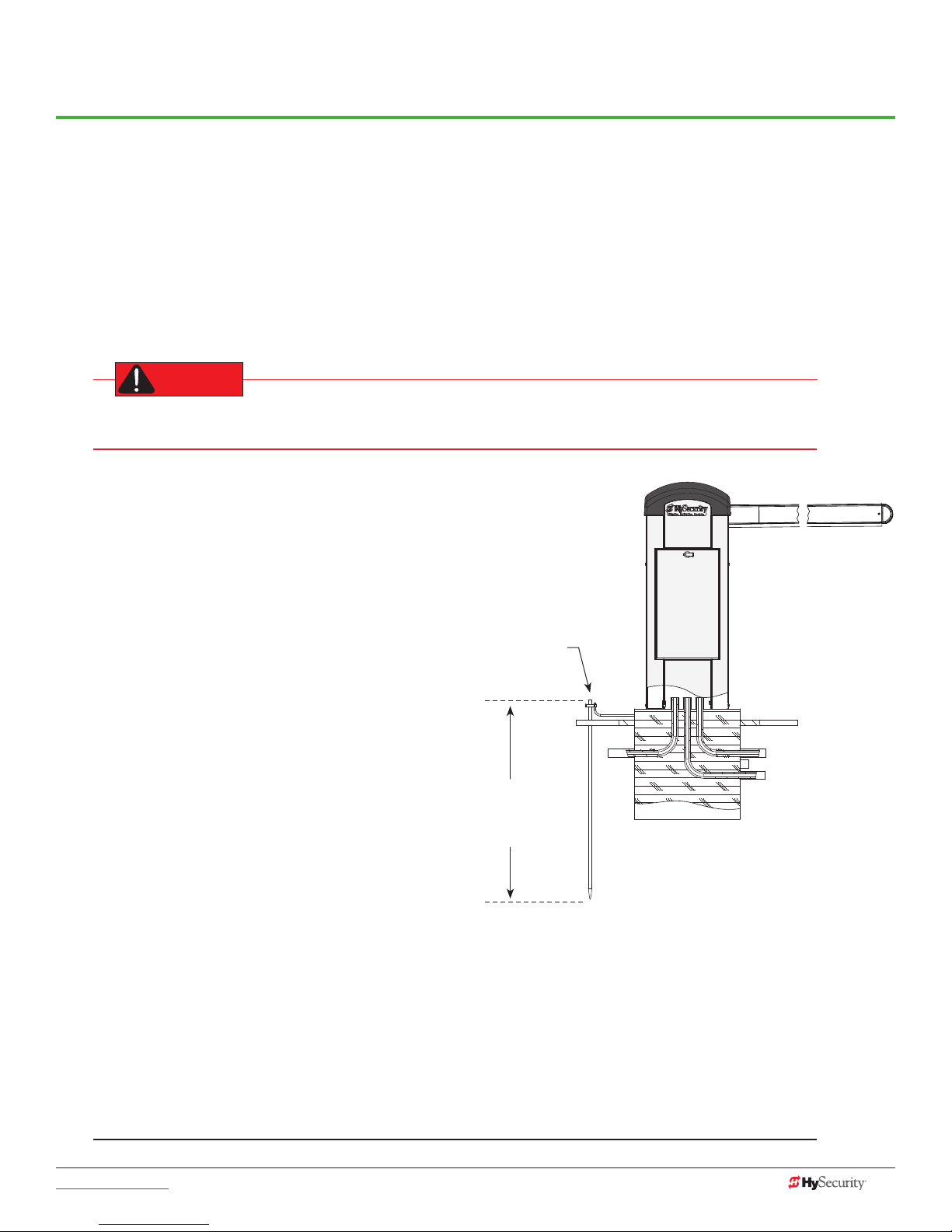
InstallIng tHe eartH ground
An earth ground refers to the grounding rod and accompanying equipment ground which need to be installed
to safeguard against potential electrical shock and damage to personnel and equipment.
The potential for lightning discharge exists with all gates, fences and gate operators. National Electric
Code (NEC) - Article 250 requires a separate earth ground in addition to the required equipment ground.
HySecurity recommends grounding the operator with
a separate earth ground rod (or a similar device in the
case of crash products) to shield the operator against
electromagnetism and other electrical signals that
may cause, erratic operation with, or damage to, the
Smart DC Controller and other electrical parts.
For earth grounding requirements in the U.S.A., refer
to the National Fire Protection Association (NFPA) 780
- Standard for the Installation of Lightning Protection
Systems. Highlights of the standard include:
• The ground rod must be UL listed copperclad steel, solid copper, hot-dipped
galvanized steel, or stainless steel. Minimum
requirements: ½ inch (13 mm) diameter and 8
feet (244 cm) in length.
• The ground rod is driven into the earth (refer
to local codes for proper depth requirements).
• The ground rod is electrically bonded to the
chassis with a single length of un-spliced
6AWG copper wire less than 3 feet (91cm)
long. Due to the large concrete foundation
on crash products, make the necessary
adjustments to accommodate for earth
ground requirements.
• Local jurisdictions may impose other requirements above the NEC, Article 250 and NFPA 780. Consult
the local codes and regulations regarding requirements in your area.
Earth ground
Consult
local codes
for required
depth
NOTICE: Properly grounding the gate operator is critical to gate operator performance and the life of its
electrical components. Use sufcient wire size during installation. If you do not ground the operator with a
separate earth ground, you risk voiding the HySecurity Warranty.
www.hysecurity.com © 2017 Power MX3650-01 Rev. D 13
Page 24
WIrIng aC poWer
DANGER
CAUTION
WARNING
CAUTION
The StrongArmPark DC has separate Installation Instructions that explain how to connect to AC power. For
reference purposes, the same information is provided below.
Size the primary wires. Consider the voltage and length of the wire run from the main power panel. Make sure
you have set the voltage selector switch to the proper voltage.
Turn OFF AC power at the source (circuit breaker panel) before accessing the wires in the
StrongArmPark DC. Follow facility Lock Out/Tag Out procedures. Make sure all power switches are in
the OFF position. Follow all electrical code standards and regulations.
Wiring of gate operators must conform to NFPA and NEC standards and comply with all local codes. When the
installation is compliant and complete, turn on AC power at the source and power module.
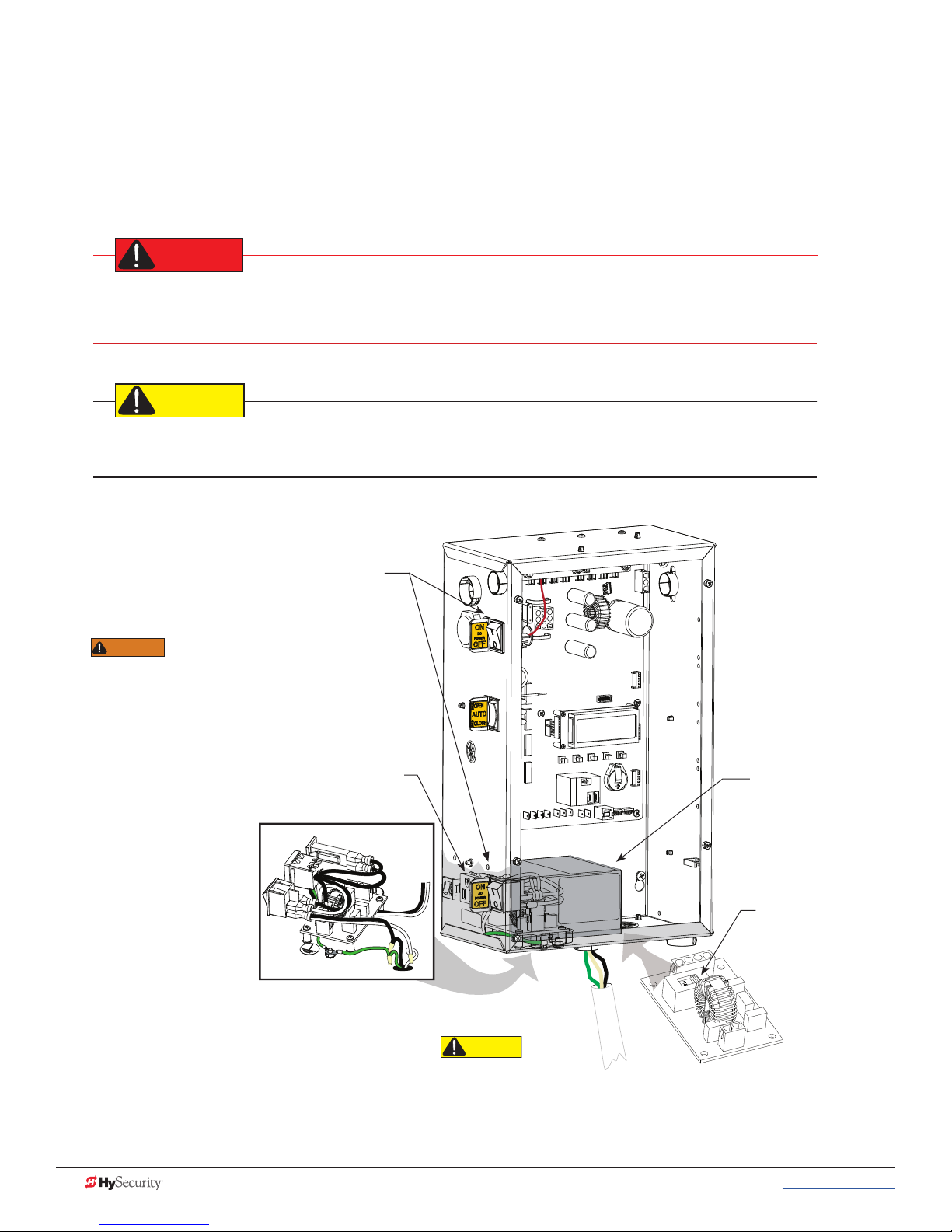
Place power switches
in OFF position.
DO NOT connect the
115VAC service outlet to
208 or 230VAC power supply wires! To use
the 115VAC service outlet on a 208 or
230VAC installation, the electrician needs
to run an extra neutral wire to the operator
from the power source and wire the service
outlet per code.
Service outlet
SERVICE OUTLET
115 VAC, 15A
115 1Ø
USE ONLY COPPER
CONDUCTORS WITH
A TEMPERATURE RATING
OF AT LEAST 75 °C
FACTORY CONFIGURED
High voltage cover
Voltage selector
switch is factory
set to 115V.
14 MX3650-01 Rev. D StrongArmPark DC Programming & Operations © 2017 www.hysecurity.com
When connecting
to 208/230VAC
power, the voltage selector
switch on the AC power board
must be moved to the 230V
position or damage to the
operator will occur and void the Warranty. The label on the high voltage cover
must be changed to state 230V.
Page 25
Wiring 115VAC Power
CENTER LOOP
For standard 115VAC power connection:
Verify AC power supply wires and low voltage (12V & 24V accessory
power wires) run through two separate conduits. The higher voltage
from the AC power supply may cause interference and anomalies in
StrongArmPark DC operation if the high and low voltage wires are
routed through the same conduit.
Maximum gate operator current draw is 3 Amps on a dedicated
115VAC circuit (20A dedicated circuit is recommended).
Make sure proper wiring is being used. The following table shows the
maximum allowable wire run from the power source to the operator for
various wire sizes.
LED indicator changes color:
GREEN indicates AC power and RUN mode.
YELLOW designates MENU mode.
RED indicates Alert, Fault, or Error.
USER RELAY 1
Electro-mechanical
INSIDE LOOP OUTSIDE LOOP
StrongArmPark DC 115VAC: Wire Gauge versus Run
AC Power 14 Gauge Wire 12 Gauge Wire 10 Gauge Wire
One operator 115V 730 ft (223 m) 1200 ft (366 m) 1900 ft (579 m)
Two operators 115V 460 ft (140 m) 750 ft (228 m) 1160 ft (354 m)
NOTE: Table 2 assumes a dedicated circuit with an accessory power load up to 2A.
Additional loads require that the wire size be increased or the distance of the run be decreased.
RED ashing LED indicates software and
power is operational. Pulsating LED slows
when only DC power supplied.
To connect to 115VAC power, take the following steps:
1. Make sure the AC power is turned off at its source and the DC and AC power switches on the operator
are in the off position.
2. Access the input power wires and service outlet wires by removing the two Phillips-head screws that
secure the high voltage junction box cover.
3. The service outlet wires are solid copper and are labeled and bound together to keep them separate
from the AC power switch wires.
4. Wire nut or crimp bond the power supply wires to the black and white lead wires coming from the AC
power switch (no label).
5. Wire nut or crimp bond the equipment ground wire to the green ground wire in the junction box.
6. To activate the 115VAC service outlet, include the black and white outlet lead wires and the green
ground wire in the connections made above.
7. Neatly organize all wire connections and replace the high voltage junction box cover. Secure it with the
two Phillips-head screws.
www.hysecurity.com © 2017 Power MX3650-01 Rev. D 15
Page 26
Wiring 208/230VAC Power
CAUTION
DANGER
All StrongArmPark DC operators are shipped from the factory as 115VAC units. When connecting to 208/230VAC
power, the voltage selector switch on the AC power board must be moved to the 230V position or damage to the
operator will occur and void the Warranty
For the 208/230VAC power connection:
• Verify AC power supply wires and low voltage (12V & 24V accessory power wires) run through two
separate conduits as discussed in Wiring 115VAC Power.
• Maximum gate operator current draw is 1.5 Amps on a dedicated 208/230VAC circuit (20A dedicated
circuit is recommended).
• Make sure proper wiring is being used. See the chart below.
StrongArmPark DC 208/230VAC: Wire Gauge versus Run
AC Power 14 Gauge Wire 12 Gauge Wire 10 Gauge Wire
One operator 208/230V 2095 ft (639 m) 3350 ft (1021 m) 5300 ft (1615 m)
Two operators 208/230V 1465 ft (446 m) 2350 ft (716 m) 3750 ft (1143 m)
To connect to 208/230VAC power, take the following steps:
1. Make sure the AC power is turned off at its source and the DC and AC power switches on the operator
are in the off position.
2. Remove the High Voltage Protection cover by unscrewing the two Phillips-head screws that secure it.
3. Toggle the voltage selector switch from 115V to 230V.
4. Access the input power wires by removing the two Phillips-head screws that secure the High Voltage
Junction Box Cover.
5. Wire nut or crimp bond the power supply wires to the black and white lead wires coming from the AC
power switch.
6. Wire nut or crimp bond the equipment ground wire to the green ground wire in the junction box.
To use the service outlet with 208/230VAC, a separate neutral wire (white) must be run from the power
source. Make sure the incoming power wires are sized appropriately to support the load expected on
the service outlet. Follow guidelines per the National Electrical Code Article 250.
7. Neatly organize all wire connections and secure the Junction Box Cover with the two Phillips-head
screws.
8. Place the 208V or 230V 1Ø label on the Junction Box Cover over the 115V 1Ø label.
16 MX3650-01 Rev. D StrongArmPark DC Programming & Operations © 2017 www.hysecurity.com
Page 27
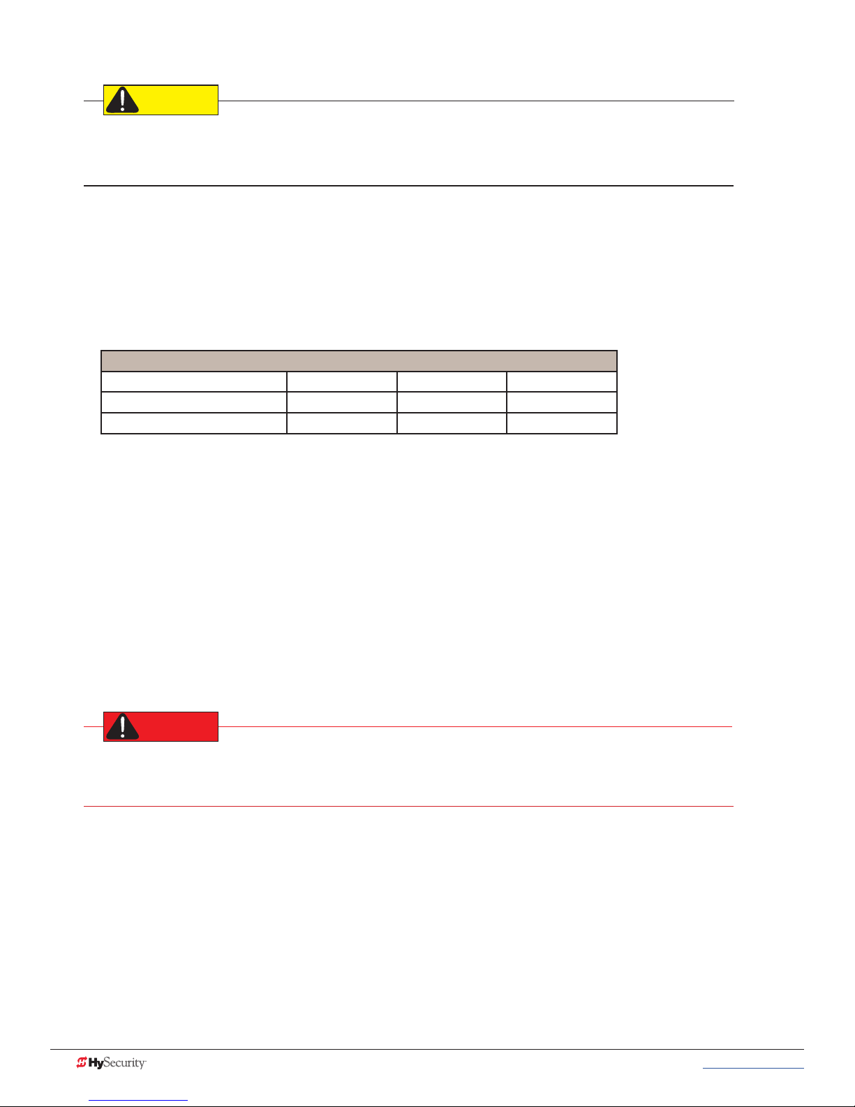
Connecting DC Power
PREV
Red spade
connector
To connect the DC power:
1. Turn off the DC and AC power switches.
2. Slide the plastic cover off the control box.
3. Attach the red spade connector to the battery
terminal on the DC power switch.
Status light
Turning the Power Switch ON
When both DC and AC power switches are turned ON:
• The barrier arm travels open and initiates a target
search. StrongArmPark DC senses the arm position
and establishes its open and close limits. No
physical limit switches exist. Limits are automatically learned and remain intact even if AC power is lost
and the batteries are fully drained. The only exception occurs when factory defaults are reinstated, or
the Smart DC Controller is replaced. For more information about Learn Limits and Menu modes, refer
to Display & Menu Options on page 19.
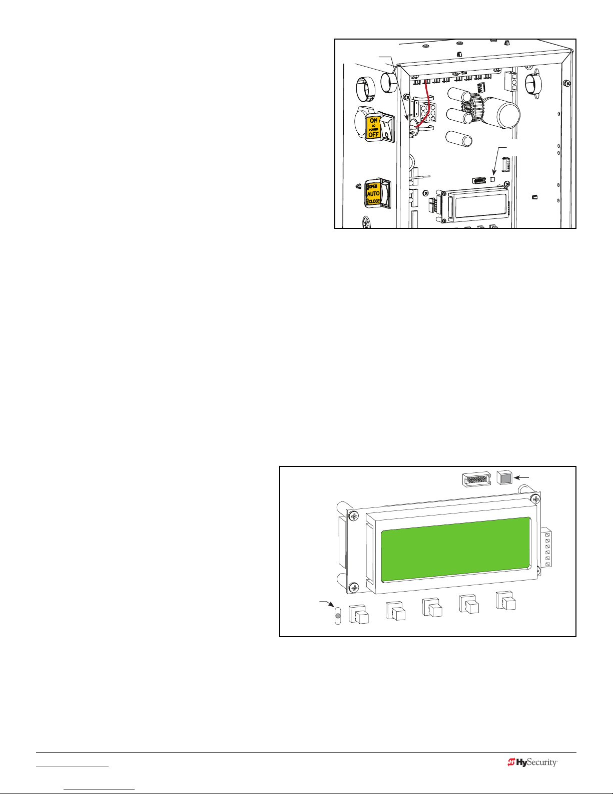
• A green status LED appears on the Smart DC Controller and remains static. The status light appears
above the display and indicates that the processor is receiving power.
NOTE: The Smart DC Controller can be powered when either switch is turned on. However, the operator is a DC-powered unit and
runs on its batteries. If the DC power switch is off, the operator will not function (even though the AC power switch is on). When the
operator is connected to AC power and the both AC and DC power switches are turned on, the charge level of the battery is being
monitored and maintained. On a solar-powered operator, the AC power switch connects and disconnects the DC power from the
solar panels.
The ashing red indicator light next to the OPEN button on the Smart DC Controller is considered the heart
beat of the system. It indicates that the electronics board is receiving power. When AC power is lost, the rate of
ashing slows down. Another indicator light, above the display, is multi-colored and corresponds to the action
that the operator is performing:
• Green - the operator is stopped.
Green LED
• Flashing yellow - the operator is running.
• Red - the operator has experienced an
error.
• Not lit - AC power is lost. Pressing the
SHOW LEDs button indicates which
inputs, if any, are active. Refer to Figure
4-2 for the SHOW LEDs location on the
board.
Red LED
ashes
indicating
processor is
working.
OPEN
CLOSE
NEXT
STOP
SELECT
MENU
RESET
www.hysecurity.com © 2017 Power MX3650-01 Rev. D 17
Page 28

Page intentionally left blank
18 MX3650-01 Rev. D StrongArmPark DC Programming & Operations © 2017 www.hysecurity.com
Page 29
Display & Menu Options
Highly sophisticated software provides three different modes of operation: run, program, and fault.
How to navigate using the Smart DC Controller (SDC) keypad, interpret status display codes and program the
operator is found in this section.
InItIal setup
Once you have completed the installation, attached accessories and
turned power ON, you’re ready to program the operator. Two different
approaches exist:
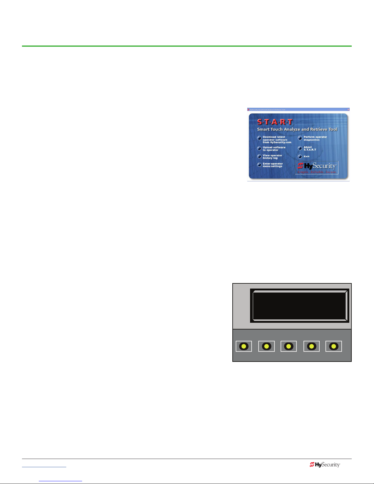
• Connect a laptop computer to the serial (RS-232 or USB) port,
check for the most current software version and then set the
operator menu congurations via the START software.
See Smart Touch Analyze and Retrieve Tool (S.T.A.R.T.) on page
71.
NOTE: Use a laptop computer at your place of business to conveniently download the free START software and
most current software version from www.hysecurity.com before heading out into the eld. This makes
it easy to adjust settings using a laptop.
• Manually navigate through the User and Installer Menus using the SDC keypad. The instructions for
performing this second option are provided in this section.
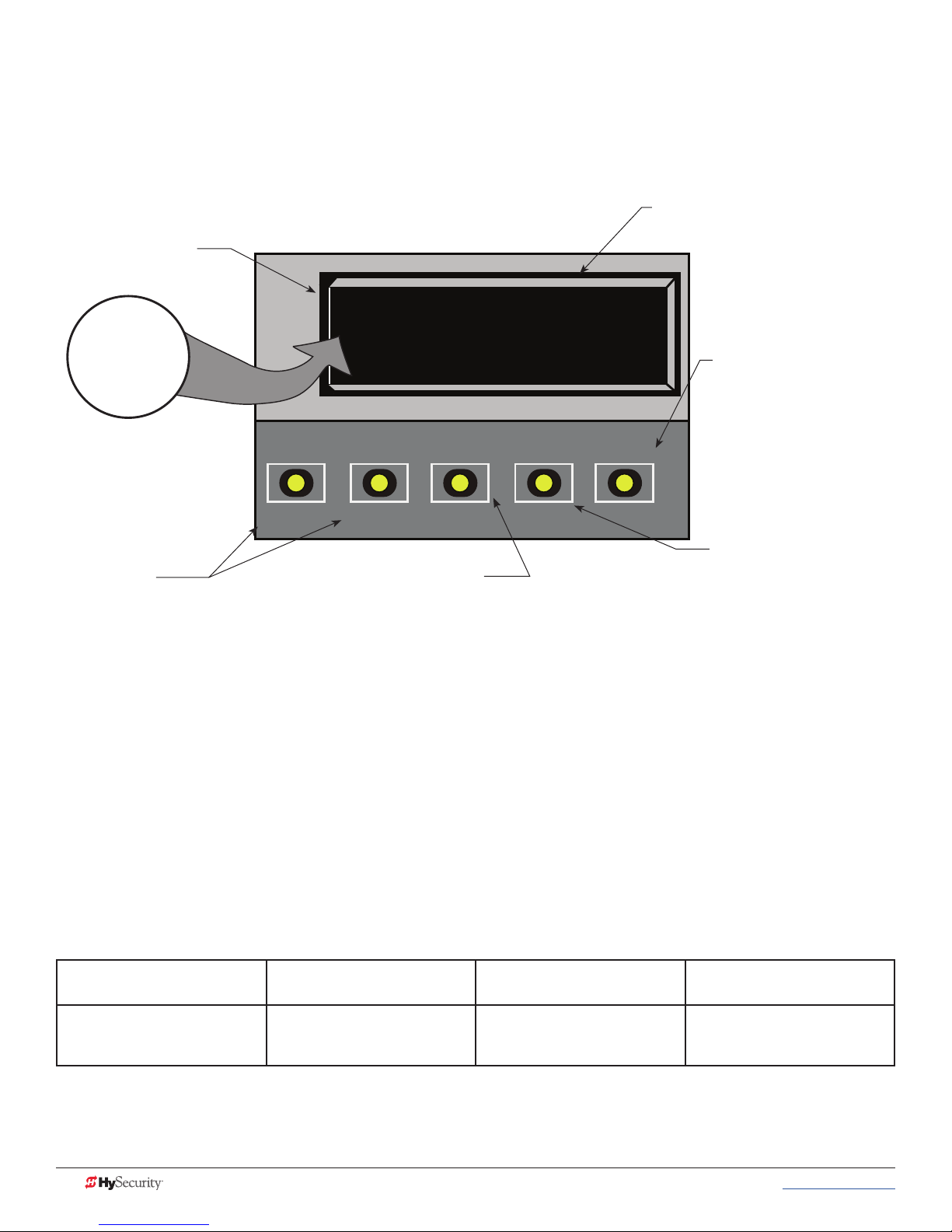
understandIng tHe dIsplaY and keYpad
The SDC display and keypad provide access to the operator’s sophisticated software and functionality.
Three different operational modes exist:
• Run Mode - gate is operational, awaiting commands.
• Menu Mode - motor disengages and operator
commands are ignored. Data entry, menu navigation, and
menu selection can be accomplished via the keypad or
through a S.T.A.R.T. software connection using the RS-232
or USB port.
• Fault Mode - alerts, faults, or errors appear on the
display. Some errors or faults can be reset with the Reset
button while more serious faults require additional
troubleshooting. Faults indicate a need for diagnosis and
resolution. Refer to Troubleshooting.
OPEN
PREV
HYSECURITY
GATE STOPPED
CLOSE
NEXT
Display in Run Mode:
Stop, Open, or Close
STOP
SELECT
MENU
RESET
The keypad lets you navigate, change, or clear the information in the display menus. The singular use of these
keys is dependent on the operator mode.
The buttons with text above and below have two functions. Use these buttons to enter operating commands
or navigate through the User and Installer Menus.
www.hysecurity.com © 2017 Display & Menu Options MX3650-01 Rev. D 19
Page 30
menu mode
In Menu Mode, the motor disengages and operator commands are ignored. Data entry, menu navigation, and
menu selection can be accomplished using the buttons on the Smart DC Controller keypad.
NOTE: Menu Mode automatically returns to Run Mode if no activity (i.e. key presses) occurs for two minutes.
Two blinking characters
indicate that the display
will accept changes.
CT
NEXT or PREV
Navigational buttons.
Pressing Next or Previous
scrolls through the selections.
OPEN
PREV
32-character display provides codes
which provide information about the
menu items.
CT 0 (OFF)
CLOSE TIMER
CLOSE
NEXT
Pressing Select
causes the left most two characters to blink, (CT in
the example), which indicates the display is ready
to accept changes to a menu setting.
Use the navigational buttons to view selections.
Press Select a second time to accept what
appears on the display. Entry mode is exited, the two characters
stop blinking, and Next or Previous must be pressed to move onto a
different display. Pressing Program exits to Run mode.
STOP
SELECT
MENU
RESET
The Reset button is disabled
while in Program Mode.
The Menu button accesses
program mode. When the
menu item is selected and
blinking, the Menu button
has no function. However,
pressing Menu when the
2 characters are static
(not blinking), returns the
operator to Run Mode.
The 32-character LCD display limits what can be communicated with words. If you do not understand the
abbreviated word or acronym, please review the User Menu and Installer Menu sections.
menu mode navIgatIon
Navigating within the program menus is easy once you learn how the keypad buttons function. Refer to the
following chart.
Smart DC Controller: Menu Mode Navigation Buttons
To change that data
appearing in the display
Press Select.
Two left characters blink.
20 MX3650-01 Rev. D StrongArmPark DC Programming & Operations © 2017 www.hysecurity.com
To navigate through the
Selections
Press Next or Previous.
Continue pressing Next to view
all selections.
To choose what appears on
the display
Press Select.
Blinking characters
become static.
To navigate between menu
items
Press Next or Previous.
Advance - press Next
Previous - press Previous
Page 31
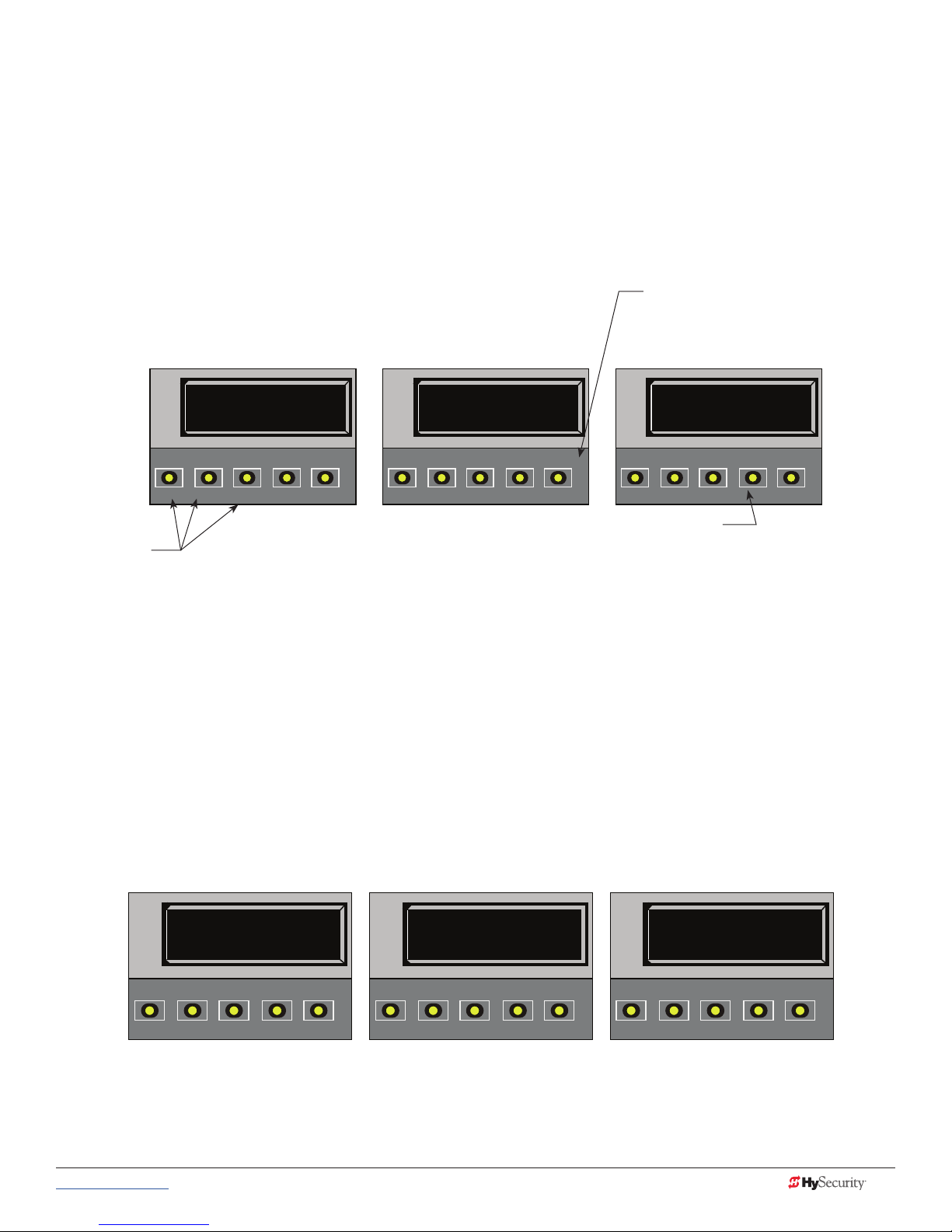
run mode
The Run Mode displays appear static when the operator is ready and waiting for a run command. When the
display is ashing “GATE OPENING” or “GATE CLOSING”, a command has been received and the barrier
gate is in motion. The command may come from a variety of sources: a card reader, push-button remote,
or recognition of a vehicle passing over a loop detector. In all cases, the operator “runs” the motor when it
receives an operational command.
Three displays indicate the position or status of the barrier gate. The keypad entry used to access the User or
Installer menus, begins at one of these Run Mode displays.
Pressing Reset clears alerts or faults and
returns to Run Mode.
NOTE: Press Reset at any Run mode
status display to view the software version.
For example: h5.33
HYSECURITY
GATE OPEN
CLOSE
OPEN
NEXT
PREV
STOP
SELECT
MENU
RESET
HYSECURITY
GATE CLOSED
CLOSE
OPEN
NEXT
PREV
STOP
SELECT
MENU
RESET
HYSECURITY
GATE STOPPED
CLOSE
OPEN
NEXT
PREV
STOP
SELECT
MENU
RESET
Pressing Menu scrolls through operator status
Pressing Open,
Close, or Stop
causes the gate
displays and accesses the User Menu.
Note: Pressing the MENU button twice, bypasses
the operator status displays.
to perform the
command.
Run Mode Displays
NOTE: To access the User or Installer menus, the motor cannot be engaged and the barrier gate cannot be moving.
vIeWIng operator status dIsplaYs
Press the MENU button once and the operator status displays scroll past in two second intervals. Pertinent
information appears to provide a quick overview of the operator’s status or congurations.
The type of information that may scroll across the display includes: software version, operator type (OT), gate
handing (LEFT HAND or RIGHT HAND), buss voltage, and life cycle counter.
HYSECURITY
V5.32
OPEN
PREV
CLOSE
NEXT
STOP
SELECT
MENU
RESET
www.hysecurity.com © 2017 Display & Menu Options MX3650-01 Rev. D 21
LEFT HAND
OPEN
PREV
CLOSE
NEXT
STOP
SELECT
MENU
RESET
Example of Operator Status Displays
BULK
CHARGER STAT E
CLOSE
OPEN
NEXT
PREV
STOP
SELECT
MENU
RESET
Page 32

user menu
The User Menu consists of several items which can be modied using the Smart DC Controller keypad.
Access:
Pressing the MENU button, at one of the static Run Mode displays, causes the operator status displays to scroll
past, stop and display the rst user menu item.
When the Close Timer (or Hold to Close “HC”) display appears, it means you have accessed the User Menu.
The Close Timer display is the rst in a cyclical series of User Menu displays.
NOTE: To access the User Menu, the operator must be in Run Mode. To bypass the operator status displays, press the Menu button a
second time.
Use the navigational buttons, Select, Next, and Previous to change or view
the menu functions. Table 1 describes the User Menu items and supplies the
CT 0 (OFF)
CLOSE TIMER
factory defaults. (Factory default settings shown in bold.)
CLOSE
OPEN
STOP
Table 3: User Menu
SELECT
PREV
Table 3: User Menu
User Menu Setting Options Menu Tasks & Explanations SDC Wire Connections
CT 0 (OFF)
Close Timer
HC 0 (OFF)
Hold to Close
HO 0 (OFF)
Hold to Open
AP 0 AC LOSS
UPS FAIL OPEN
RO 0 (OFF)
Radio Open/Close
0 = Timer disabled (OFF)
1 second to 99 seconds
0 = off
1 = on
0 = off
1 = on
0 =
UPS FAIL OPEN
1 = UPS FAIL CLOSE
2 = AUTO OPEN
3 = NO CLOSE TIMER
0 = off
1 = on
The Close Timer assigns how many seconds
before the open gate initiates closure.
Keep the setting at 0 if a hard-wired, push-button
control device is being used. Refer HC.
NOTE: When the Hold to Close is set to 1, the
Close Timer display does not appear and HC1
becomes the User Menu entry display.
Set to 0 to produce an gate closure when a
momentary signal is transmitted.
Set to 1 if a constant hold to close signal, such as
a push button control, is being used. A setting of
1 also deactivates the automatic close timer and
causes its menu to disappear. The Hold to Close
replaces the Close Timer display as the User Menu
entry display.
Similar to Hold to Close, but congures the Open
inputs for a constant-hold function.
Set to 1, a constant hold to open signal, such as a
push button control, must be in use.
The setting congures how the gate functions
when AC power fails.
A setting of zero, congures radio input for open
only. Setting 1 adds the capability for radio input
to close the gate, but only when it is fully open.
NEXT
Not applicable (N/A)
COM
Close
COM
Open
COM
COM
RADIO Open
MENU
RESET
22 MX3650-01 Rev. D StrongArmPark DC Programming & Operations © 2017 www.hysecurity.com
Page 33

Table 3: User Menu
User Menu Setting Options Menu Tasks & Explanations SDC Wire Connections
BF 0 (OFF)
Warn Before Operate
FA 0 (OFF)
Forced Open Alert
DA 0 (OFF)
Drift Close Alert
PE 0 (OFF)
Photo Eye Alignment
CL 0
Set Clock
LD 5
LCD Contrast
LG 0 (OFF)
VIEW EVENT LOG
0 = off
1 = warning buzzer on
throughout Gate travel
2 = warning buzzer on for 2
seconds of Gate travel
0 = off
1 = on
0 = off (standard)
1 = on (detailed)
0 = off
1 = on
0 = Display
1 = Set Clock
5
0 through 9
0 = OFF
1 = On
Controls the warn-before-operate buzzer and can
be congured three ways:
Set to 0: Buzzer is disabled. The buzzer will still
beep if alerts, faults, errors, or entrapment occur.
Set to 1: Buzzer beeps for 3 seconds before gate
moves and continues through entire length of
travel.
Set to 2: Buzzer beeps for 3s before gate moves
and continues for 2s of travel.
Intended for highly secure facilities.
Set to 1, the operator sounds the 3-second “warn
before operate” buzzer alarm and initiates a
closure if the gate is forced open and the closed
limit switch disengages. The motor starts to secure
the gate. If the gate does not fully close within 4s,
the motor turns off and the buzzer sounds for 30
seconds. The display shows ALERT 1 - FORCED
OPEN.
Set to 1, the operator sounds the 3-second “warn
before operate” buzzer alarm and initiates an
open command if the gate is forced, or drifts, off
the open limit switch. The motor starts to reopen
the gate. The motor runs for a maximum of 4s
and, if the gate is not fully open at the end of this
period, the buzzer sounds for 10s. The display
shows ALERT 2 - DRIFT CLOSED.
Set to 1, the operator serves as an aide in photo
eye transmitter/receiver alignment. The buzzer
chirps once when the emitter and receiver are
not aligned. When the emitter and receiver are
aligned, the buzzer chirps twice. If they go out of
alignment again, the buzzer will chirp once. The
Alignment Mode is reset with a close-limit input or
by pressing the Reset button.
NOTE: If the operator doesn’t run when the
power switch is initially turned ON, check the
alignment of the photo eye and all the photo eye
connections.
To adjust the hour, minute, day, or month to a
different time zone, select 1. Once the clock is set,
the display returns to the 0 setting.
This feature is useful to read historic operational
data, which can be accessed with a computer via
the USB or RS-232 port.
Adjusts the contrast of the display. Available
settings from low contrast 0 to 9 high contrast,
with a factory default setting of 5.
NOTE: While the Operator Status Displays are
scrolling, you also have the ability to adjust the
contrast by pressing the PREV and NEXT buttons.
View the Event Log using the gate operator
keypad and display. For more information, refer to
Access the Event Log through the User Menu on
page 67.
Not applicable (N/A)
N/A
N/A
EYE Open
EYE Close
EYE COM
N/A
N/A
N/A
www.hysecurity.com © 2017 Display & Menu Options MX3650-01 Rev. D 23
Page 34

Table 3: User Menu
User Menu Setting Options Menu Tasks & Explanations SDC Wire Connections
US 0
CLEAR COUNT
DS 0 (OFF)
Diagnostic Logs
PD 0
Set Password
0 = preprogrammed limit
1 = Clear Transient count
2 = Clear Tenant count
3 = Clear Special count
4 = All User
0 = off
1 = detailed
0 = Off
1 = On, Set Password
Clears the logs (counts) of “user types” entering
or exiting through the StrongArmPark DC gate.
This menu is used most often in Parking lot and
revenue control scenarios. Selecting a number and
pressing SELECT again, clears the count.
Set to 0, the SDC logs pertinent operator events
such as faults, errors, or menu manipulation. When
experiencing intermittent problems, set this item
to 1 to record all operator open and close events,
in addition to the normal alert, fault and error logs.
This parameter automatically resets to the default
0 (off) after 24 hours.
To enter a password (up to 80 characters) for
network connectivity, select 1. You can use the
menu navigation buttons to enter the password
(SELECT, NEXT, SELECT). When the password is
set, the display returns to the 0 setting.
NOTE: A System Address (SA) value in the Installer
Menu must be set before the Set Password display
can appear in the User Menu.
COM
TRANSIENT USER
TENANT USER
SPECIAL USER
USB or RS-232 cable
and laptop computer
loaded with HySecurity
free S.T.A.R.T. software
is required to read the
log le.
Visit www.hysecurity.com
Network: Ethernet or
RS-485
Installer menu
CT 0 (OFF)
The Installer Menu options provide more advanced congurations for
the gate operators. Access to the Installer Menu is through the User
Menu. The navigational buttons are the same in both menu modes.
OPEN
Access:
While a static Run Mode code is being displayed, press the MENU
PREV
button twice. (Bypasses the operator status displays.)
When the Close Timer display appears:
1. Access the Installer Menu by simultaneously pressing and
holding the RESET and OPEN buttons.
2. Release both buttons and the Learn Limit display appears. The
LL display is the rst item in the Installer Menu.
NOTE: Installer Menu options can also be congured through the use of a
laptop computer and the S.T.A.R.T. software.
Table 4 describes the Installer Menu items and supplies the factory defaults. (Factory settings shown in bold.)
CLOSE TIMER
CLOSE
LL 0 (OFF)
LEARN LIMIT
OPEN
PREV
CLOSE
NEXT
NEXT
STOP
SELECT
STOP
SELECT
MENU
MENU
RESET
RESET
24 MX3650-01 Rev. D StrongArmPark DC Programming & Operations © 2017 www.hysecurity.com
Page 35

Table 4: Installer Menu
Table 4: Installer Menu
Installer Menu Setting Options Menu Tasks & Explanations SDC Wire
Connections
OT 0
Set Operator Type
MN 0
Model Number
LL 0 (OFF)
Learn Limit Reset
UC 0
Usage Class
SH 0
Gate Handing
OS 1
Open Speed
CS 1
Close Speed
FD 0 (OFF)
Load Factory Defaults
DG 0 (OFF)
Dual Gate
0 = operator type
12 = SwingSmart DC 20 & DCS 20
Solar
14 = StrongArmPark DC 10 & DC14
DCS 10 Solar & DCS 14 Solar
15 = SlideSmart DC 15 &
DCS 15 Solar
16 = SlideSmart DC 10F &
DCS 10F Solar
0 = model type unknown
1 = Model 10
2 = Model 14
0 = Normal setting
1 = Erases learned limit positions
0 = gate disabled
1 = Family dwelling (1 to 4 units)
2 = Multi-family & commercial
3 = Light industrial*
4 = Industrial/guarded secure*
*Not serving the general public
0 = gate disabled
R = viewed from the secure side, the
arm lifts right to open
L = viewed from the secure side, the
arm lifts left to open
DC10 DC14
1 = 2.5 seconds 1 = 3.5 seconds
2 = 2.0 seconds 2 = 3.0 seconds
3 = 1.5 seconds 3 = 2.5 seconds
1 = 2.5 seconds 1 = 3.5 seconds
2 = 2.0 seconds 2 = 3.0 seconds
3 = 1.5 seconds 3 = 2.5 seconds
0 = user settings
1 = reload factory settings
0 = solo operator
1 = Slave unit
2 = Master unit
3 = Sally Port A
4 = Sally Port B
Select the appropriate number for the
operator.
NOTE: This menu item only appears if the
Smart DC Controller is being replaced.
CAUTION: If you are replacing an SDC
board, remember to transfer the operator’s
menu settings from the existing board
to the replacement board. Refer to the
installation instructions that accompany the
replacement SDC board.
Select the type of StrongArmPark DC model
used at the site. NOTE: This menu item only
appears when you set the OT (operator type).
Set to option 1, the system resets to
accommodate for relearning limits.
Set the UL usage class. The installer must set
the usage class for the operator to function.
See Identifying Gate Operator Category and
Usage Class on page 7.
NOTE: The usage class setting does not
appear on StrongArmPark DC and Crash
products.
The handing determines which way the gate
opens as you view it from the front access
panel. NOTE: StrongArmPark DC is factory
congured for left handing.
Adjust how quickly the barrier arm opens.
Adjust how quickly the barrier arm closes.
Select setting 1 to return the operator to
factory defaults which globally restores all
menu settings back to new operator status.
NOTICE: If factory defaults are restored,
any customized menu settings will need to
be reprogrammed. Before loading factory
defaults, you can save your customized menu
settings using a PC laptop & S.T.A.R.T.
Establishes communication after wiring dual
gate connections between two operators
in Master/Second (Slave) or Sally Port site
congurations.
This menu item appears if the sequenced gate
menu item SG is set at 0 (off).
Not applicable
(N/A)
N/A
N/A
N/A
N/A
N/A
Dual Gate COM
(Gate 1) to Dual
Gate COM (Gate 2)
A to A
B to B
www.hysecurity.com © 2017 Display & Menu Options MX3650-01 Rev. D 25
Page 36

Table 4: Installer Menu
Installer Menu Setting Options Menu Tasks & Explanations SDC Wire
Connections
SG 0 (OFF)
Sequenced Gate
CH 0 (AC)
Charger Type
BT 0 (STANDARD)
Battery Type
FO 0 (OFF)
Fire Dept Open
SE 0
IES Sensitivity
LC 0 (0.0 SECS)
Leaf Delay Close
LO 0 (0.0 SECS)
Leaf Delay Open
EC 0 STOP ONLY
Eye Close Logic
0 = off
1 = Loop Layout/Site #1
2 = Loop Layout/Site #2
0 = AC powered charger
1 = Solar powered charger
0 = standard 8Ah
1 = extended (50 Ah)
2 = maximum (110 Ah)
0 = disabled
1 = enabled
0 = Maximum (highest) sensitivity
1 = Moderate sensitivity
2 = Least sensitivity
0 = none
1 through 20
For example:
1 = ½ second
4 = 2 seconds
20 = 10 seconds
0 = none
1 through 20
For example:
1 = ½ second
4 = 2 seconds
20 = 10 seconds
0 = Close eye stops only
1 = Reverse to full open with barrier
gates (2 second reverse to open on
swing, slide, or vertical gates)
Establishes communication after wiring two or
more operators as sequenced gates.
This menu item only appears if the Dual Gate
menu item DG is set at 0 (solo operator).
NOTE: Access the User Menu in both
operators and set a Close Timer.
Assigns charger type.
If a solar-powered unit is ordered and delivered
factory-ready, this menu will not appear.
NOTE: Menu item does not appear on an AC-
powered operator.
Assign the battery type used by the operator.
Smaller batteries are charged with less current
to avoid overheating and larger batteries are
charged with more current to supply a more
rapid charge.
Provides the Fire Dept. Open input and allows
a button to activate the emergency open when
connected to +24VDC. When set to 1, the
open signal received by the operator overrides
all photoelectric eyes and edge sensors, and
opens the barrier arm. Pressing the Reset or
Open button is required before the barrier arm
can be closed.
Adjusts the sensitivity of the dynamic reversing
sensor. Available settings are 0 to 2. Zero is the
default and reacts quickly (high sensitivity) to
impediments.
NOTE: For StrongArmPark DC, adjust the
spring to prevent false trips prior to changing
the sensitivity.
Delays gate closure. This menu option appears
if the gate operator is designated as a dual
gate system (Master/Second, for example).
Available settings are 1 to 20. Each increment
adds ½ second, to a maximum of 10 seconds
time delay, before the operator activates
when commanded to close.
Delays gate opening. This menu option
appears if the gate operator is designated
as a dual gate system (Master/Second, for
example). Available settings are 1 to 20. Each
increment adds ½ second (with a maximum of
10 seconds) time delay following a command
to open before the operator activates.
The default setting is non-reversal if the close
photo eye is triggered. A setting of 1 causes
the barrier arm to reverse and travel full open if
triggered while closing.
Connect Dual Gate
COM (Trafc Gate)
to
Dual Gate COM
(Security Gate)
A to A
B to B
Extended and
maximum batteries
require separate
housing and wiring.
+24V
Fire Dept Open
See NOTE.
DUAL GATE inputs
on both operators
DUAL GATE inputs
on both operators
EYE Close
EYE COM
(Inputs #14 or #15)
26 MX3650-01 Rev. D StrongArmPark DC Programming & Operations © 2017 www.hysecurity.com
Page 37

Table 4: Installer Menu
Installer Menu Setting Options Menu Tasks & Explanations SDC Wire
Connections
SR 0 (FULL OPEN)
IES Sensor Logic
PC 0 NO CONTACT
Photo Eye Output
GC 0 NO CONTACT
Gate Edge Output
DT 0 FREE EXIT
Disable Function
OR 1 REVERSE
Outer Arm Loop
IR 1 REVERSE
Inner Arm Loop
DL 1 STANDARD
Detector Logic
0 = Reverses full open
1 = ½ second reversal (.5)
0 = Normal Open PE output
1 = Normal Closed (monitored)
0 = Normally Open Edge
1 = Normally Closed
0 = Disable Free Exit
1 = Disable Close Timer
0 = Pause closing only
1 = Enable reversing to open
2 = Ignore and continue closing
0 = Pause closing only
1 = Enable reversing to open
2 = Ignore and continue closing
1 = Standard
2 = Quick Close
The default setting is a ½-second duration
reversal if the dynamic reversing sensor is
triggered. The optional setting of 0 will cause
the gate to reopen fully if triggered while
closing.
The default setting is photo eyes with Normally
Open outputs. Setting 1 requires a Normally
Closed (NC) output which requires both a
photo EYE OPEN and a photo EYE CLOSE
are connected. If set for NC, the connection
is supervised and any open or short circuit
fault will generate a FAULT 2 which requires a
STOP button reset to re-enable any functions
triggered.
The default setting is edge sensor with
Normally Open (NO) output. The optional
setting of 1 requires an (NC) output.
Congures the BLOCK EXIT input to disable
either the Free Exit Detector function or,
alternately, the Timer To Close function. The
default setting disables the free exit detector.
NOTE: The free exit is disabled when the
gate is at its closed limit. If the closed limit is
not tripped, the free exit continues to work
normally.
The default is for full reversal when the loop is
triggered. A setting of 0 causes the barrier arm
to only pause when triggered. Closure begins
as soon as the loop is clear again. A setting
of 2 is provided for the most secure facilities
where it is essential that the loop trigger
is completely ignored and the barrier arm
continues closing without pause or reversal.
Congures for faster closure. This selection
determines whether the close timer begins
to count after vehicles have departed the
detector loops or whether the close timer will
count down while the loops are occupied.
The default setting 1 causes the Close Timer to
start when the Center Loop is clear. A setting
of 2 causes the Close Timer to start when the
open limit switch trips.
N/A
EYE OPEN
EYE CLOSE
4 wires total:
COM/+24
COM/ PHOTO EYE
CLOSE
COM
EDGE
COM
BLOCK EXIT
OUT OBS LOOP
(OUTER ARMING)
COM or connection
to Hy5x detector
IN OBS LOOP
(INNER ARMING)
COM or connection
to Hy5x detector
Center Loop
COM or connection
to Hy5x detector
www.hysecurity.com © 2017 Display & Menu Options MX3650-01 Rev. D 27
Page 38

Table 4: Installer Menu
Installer Menu Setting Options Menu Tasks & Explanations SDC Wire
Connections
CR 0 REVERSE
Center Loop
CB 0 (OFF)
CLD Disable ELD
CP 0 (OFF)
CLD Counts PBO
EB 0 (OFF)
ELD Backoff
RL 1 0 DISABLED
Relay 1 Logic
RL 2 0 CLOSE LIMI
Relay 2 Logic
RL 3 0 DISABLED
thru
RL 10 0 DISABLED
Relay Logic
TL 2 (45 SECS)
Open Time Alert
0 = Reopen if center loop triggers
1 = Pause only
0 = Normal operation of Free Exit
1 = Disable Free Exit
0 = Immediate closure
1 = Provides addt’l open time
0 = Normal operation of Free Exit
1 = Back off close function
0 = Disabled
1 to 38 available
0 = Disabled Relay 2 congures the function of the User 2
0 = Disabled
1 to 38 available
2 = 45 second delay
0 = 0s delay
1 = 15s
3 = 75s
4 = 105s
5 = 135s
The default allows the barrier arm to reopen if
the Center Loop detector is triggered during
closure of the barrier arm. A setting of 1 causes
the barrier arm to only pause when triggered.
Closure begins as soon as the loop is clear
again.
Setting 1 allows an CLD input to disable the
Free Exit Detector (ELD) until the barrier arm
is fully closed. Used in bi-directional trafc
situations.
The default allows the Center Loop Detector
when triggered and released, to close the
barrier arm immediately. The optional setting
of 1 designates that the Smart DC Controller
remember an additional open command if the
open input is activated a second time while
the barrier arm remains open. (For example, to
prevent a vehicle from being stranded).
The default allows normal latch open operation
of the Free Exit detector. The optional setting
of 1, creates an automatic close function if a
vehicle triggers and then backs off the Free
Exit Loop detector.
Congures the function of the User 1 output
relay. It has the capacity to switch both AC and
DC loads and can be used for high voltage
and/or high current loads. Connect devices
directly to the top of the relay: COM and either
NO and/or NC contacts.
Multiple logic function options exist. See User
Relays - Programming Procedure on page
39.
output relay, which is an electronic relay with
the capacity for switching a DC load only.
NOTE: In the StrongArmPark DC, it is
recommended to use the User 2 Relay for
connection to the LED arm lighting.
Similar to Relay 1 Logic. COM
This menu item only appears if the #8 User
Relay function has been selected. It adjusts the
time delay before activation of the User Relay
function.
Center Loop
COM or connection
to Hy5x detector
Center Loop
COM or connection
to Hy5x detector
Center Loop
COM or connection
to Hy5x detector
Free Exit Loop
COM or connection
to Hy5x detector
COM
User 1 Relay
COM
User 2 Relay
User 3 through 10
Relay
User Relay
28 MX3650-01 Rev. D StrongArmPark DC Programming & Operations © 2017 www.hysecurity.com
Page 39

Table 4: Installer Menu
Installer Menu Setting Options Menu Tasks & Explanations SDC Wire
Connections
LT 3 (75 SECS)
Loitering Alert
SA 0 (OFF)
SDC Address
ELD0 RUN MODE
Exit Loop Set
ILD0 RUN MODE
In Arm Loop Set
OLD0 RUN MODE
Out Arm Loop Set
CLD0 RUN MODE
Center Loop Set
3 = 75 second delay
0 = 0s delay
1 = 15s
2 = 45s
4 = 105s
5 = 135s
0 = No network
1 to 99 = Network “drop” address
0 = Run mode
1 = Show frequency
2 = Show call level 0-7
3 = Set Frequency
0 = Run mode
1 = Show frequency
2 = Show call level 0-7
3 = Set Frequency
0 = Run mode
1 = Show frequency
2 = Show call level 0-7
3 = Set Frequency
0 = Run mode
1 = Show frequency
2 = Show call level 0-7
3 = Set Frequency
This menu item only appears if the #13 User
Relay function has been selected. It adjusts
the time delay before activation of the User
Relay.
Sets the system address for network
communication: 0 = no network
communication
1-99 sets individual poling addresses.
See PD SET PASSWORD in Table 3: User Menu
on page 22.
Controls the Hy5x Free Exit loop detector. Hy5x
Controls the Hy5x Inside Obstruction Loop
(Inner Arming Loop) detector.
Controls the Hy5x Outside Obstruction Loop
(Outer Arming Loop) detector.
Controls the Hy5x Center Loop detector. Hy5x
User Relay
RS-485. Involves
additional hardware
& software.
Hy5x
Hy5x
www.hysecurity.com © 2017 Display & Menu Options MX3650-01 Rev. D 29
Page 40

settIng tHe tIme and date
LEARN OPEN
DEGS: +XXX.X
OPEN
CLOSE
STOP
MENU
RESET
PREV
NEXT
SELECT
LEARN CLOSE
DEGS: - XXX.X
OPEN
CLOSE
STOP
MENU
RESET
PREV
NEXT
SELECT
A feature of the Smart DC Controller is its 24-hour, 365 day clock. Make sure
it is set to the appropriate time zone. An accurate time and date allows the
diagnostic log to date stamp operational data which indicates when Alerts,
Faults and Errors occur. The log helps in troubleshooting and can be viewed
using the S.T.A.R.T. software application via a laptop connected to the USB or
RS-232 port. For more information, refer to Smart Touch Analyze and Retrieve
Tool (S.T.A.R.T.) on page 71.
To set or adjust the time or date, take the following steps:
1. At a gate status display, press the MENU button twice. This accesses
the User Menu and the CLOSE TIMER display appears.
2. Press NEXT or PREV until the SET CLOCK display appears.
3. Press SELECT.
4. CL blinks.
5. Press NEXT or PREV to change the number to 1.
6. Press SELECT to accept the display.
7. The date and time display appears. Use the SELECT and NEXT
buttons in the same manner as before to adjust the date and time.
NOTE: A date or time eld must be blinking before it
can be changed.
HYSECURITY
GATE CLOSED
CLOSE
OPEN
PREV
CT 0 (OFF)
CLOSE TIMER
CLOSE
OPEN
PREV
CL 1
SET CLOCK
CLOSE
OPEN
NEXT
NEXT
STOP
SELECT
STOP
SELECT
STOP
MENU
MENU
MENU
RESET
RESET
RESET
8. To accept what appears on the date and time display, press SELECT.
9. To exit the User Menu, press the MENU button. A gate status appears
in the display indicating you have returned to Run Mode.
NOTE: A lithium coin battery supports the clock so the date and time is retained even when
the main power is turned off. Replace the battery about every ve years with a DL 2025, DL
2032 or CR 2025 or CR 2032 battery. Refer to Clock Battery Replacement.
resettIng open and Close lImIts
Resetting the open and close limits is easily accomplished by accessing the
Installer Menu.
Status Display
GATE CLOSED
User Menu
CT 0 (OFF)
To access the Installer Menu,
press and hold RESET &
OPEN, and then release them.
Press MENU twice at
the Run Mode static display.
Installer Menu
LL 0 (OFF)
Learn Limits
LL 1 (ON)
Press Next.
Press Select.
The “LL” characters blink.
LEARN OPEN
DEGS: +XXX.X
Press Select. The Learn OPEN blinks in the display
indicating that the operator is ready to relearn the
closed limit.
SELECT
NEXT
PREV
01/05/13 00:00
^^
CLOSE
OPEN
PREV
NEXT
STOP
SELECT
MENU
RESET
30 MX3650-01 Rev. D StrongArmPark DC Programming & Operations © 2017 www.hysecurity.com
Page 41

Learn Open Limits
1. Press and hold the OPEN button while the degrees increase
toward 90 and the barrier arm reaches the desired full open
position.
2. Release the OPEN button as the arm nears full open. The motor
slows as do the numbered increments on the display. Note that if
you go too far, you can press CLOSE to reverse direction.
LEARN OPEN
DEGS: +XXX.X
CLOSE
OPEN
STOP
MENU
RESET
3. Press STOP twice to preserve the open stop location. The buzzer
PREV
NEXT
SELECT
chirps twice and the full open stop is retained in memory.
Learn Close Limits
1. Press and hold the CLOSE button while the degrees increase
LEARN CLOSE
DEGS: - XXX.X
toward - 90 and the barrier arm reaches the desired full open
position.
OPEN
CLOSE
STOP
MENU
RESET
2. Release the CLOSE button as the arm nears full open. The motor
slows as do the numbered increments on the display. Note that if
PREV
SELECT
NEXT
you go too far, you can press OPEN to reverse direction.
3. Press STOP twice to preserve the open stop location. The buzzer chirps twice and the full open stop is
retained in memory.
test tHe operator
Complete the installation by testing the operation of the gate.
NOTE: The operator must be turned on and in Run mode. A Run mode display appears on the SDC. If a Run mode status does not
appear on the display, press Reset. If an error, alert, or fault appears on the display, refer to the Troubleshooting section to learn
how to clear the display and return to Run mode.
1. Press Open to open the barrier arm.
2. Test the operator.
• Cycle the barrier arm a few times by pressing the Close and Open buttons.
NOTE: If additional accessories are to be added, read about
SDC Inputs & Wiring on page 33.
www.hysecurity.com © 2017 Display & Menu Options MX3650-01 Rev. D 31
Page 42
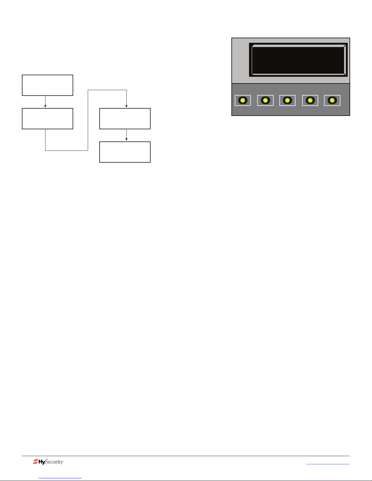
settIng tHe Close tImer
As an added security measure and to make sure the barrier
arm closes automatically within a reasonable time frame after
all loops are cleared, you must set the Close Timer.
Status Display
GATE CLOSED
OPEN
CT 15 (SECS)
CLOSE TIMER
CLOSE
STOP
MENU
RESET
User Menu
CT 0 (OFF)
CT 1 (ON)
CLOSE TIMER
PREV
NEXT
SELECT
CT 10 (SECS)
CLOSE TIMER
The Close Timer assigns how many seconds will pass before the operator initiates closure of a fully opened
barrier arm after all open commands and reversing sensor inputs have ceased and loops cleared. Every gate
operator needs to have the close timer set to a specic number of seconds (for example, 5 seconds) unless a
hard-wired closing device is connected to the unit, such as a “hold to close” push button station.
To adjust the time (1 to 99 seconds) it takes before the operator initiates gate closure, take the following steps:
1. At a gate status display, press the MENU button twice. This accesses the User Menu and the Close
Timer display appears.
NOTE: If you want gate personnel to operate the gate with the Hold to Close feature found in some push
button stations, then set the Hold to Close menu item to 1. When the Hold to Close menu item is active
(set to 1), the Close Timer menu item is unavailable.
2. Use the Select, and then Next or Previous buttons to change the number of seconds appearing on the
display.
3. To exit the User Menu, press the MENU button. The gate status appears in the display indicating you
have returned to Run Mode.
32 MX3650-01 Rev. D StrongArmPark DC Programming & Operations © 2017 www.hysecurity.com
Page 43

SDC Inputs & Wiring
This section provides information about the Smart DC Controller, its inputs for peripheral connections, and its
monitoring capabilities. This section explains how to:
• Make Connections on the Smart DC Controller
• Integrate with Security Systems
• Connect Accessory Devices
www.hysecurity.com © 2017 SDC Inputs & Wiring MX3650-01 Rev. D 33
SERVICE OUTLET
115 VAC, 15A
115 1Ø
USE ONLY COPPER
CONDUCTORS WITH
A TEMPERATURE RATING
OF AT LEAST 75 °C
FACTORY CONFIGURED
Page 44

overvIeW of tHe smart dC Controller
The Smart DC Controller uses LED’s to indicate active inputs when AC power is present. For operators that use
only DC power, you can push a button to show the active inputs. This SHOW LEDS button is at the bottom left
corner near the EMERG OPEN input.
On a new operator no active inputs should appear until external accessories and wiring are attached. If any
inputs are active before connecting external wiring, refer to Troubleshooting.
COMMON
TERMINALS
COM
COM
COM
COM
COM
COM
COM
COM
STOP
OPEN
CLOSE
RADIO
OPEN
PARTIAL
SENSOR 1
SENSOR 3
EXIT
LOOP
BLOCK
EXIT
IN OBS
LOOP
OUT OBS
LOOP
CENTER
LOOP
SENSOR 2
SENSOR
COM
+ 24 V
EMERG
OPEN
OPEN
SHOW
LEDs
24VDC
24VDC
12VDC
12VDC
Mul�-colored LED
indicates power and gate
status.
RS-232
Ethernet
expansion
USER RELAY 1
Electro-mechanical
C
D
R2
E
S
U
A
M
O
C
ht
lig
o
t
s
s
Pre
A
G
AL
U
D
ts.
u
p
n
i
ve
i
t
ac
A
R
E
T
IO
OPT
O
I
D
1
S
24V
+
EN
OP
M
O
C
B
O
N
M
O
C
S
N
USER RELAY 2
USB PORT
RS-485
COMMUNICATION
Solid state
34 MX3650-01 Rev. D StrongArmPark DC Programming & Operations © 2017 www.hysecurity.com
Smart DC Controller Board
Page 45
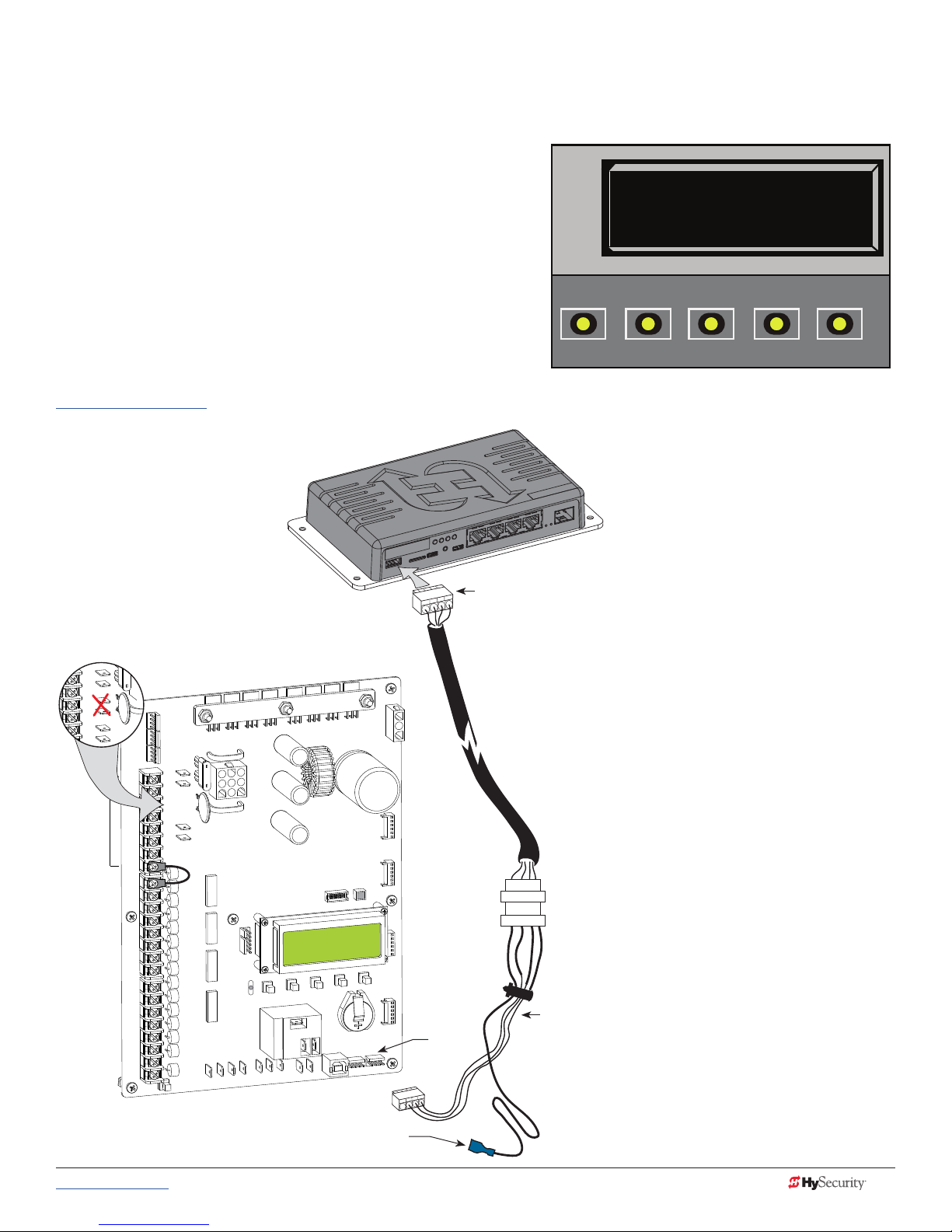
IntegratIng WItH seCurItY sYstems
24VDC
24VDC
24VAC
24VAC
12VDC
12VDC
HySecurity gate operators provide a 2-wire, serial interface (RS-485 connection) which allows remote access to
one or more operators. With software protocols provided by
HySecurity, bi-directional status updates and control
commands are easily integrated with a central controller
(computer or server), which becomes the primary (master) to
the connected operators. Several physical operators (1 to 99)
can be polled from the central master command station.
Reset requests, gate control, gate status, and gate faults can
be monitored and information can be retrieved from the
central command station.
OPEN
SA 0 (OFF)
STC ADDRESS
CLOSE
STOP
MENU
RESET
The RS-485 interface is also used to communicate with
the HyNet Gateway, a web-enabled interface. For specic
information regarding HyNet Gateway SFP 4/1, go to
www.hysecurity.com.
HyNet
RS-485
Connector
Smart DC Controller
24VDC
COM
24VDC
COM
COM
COM
COMMON
COM
COM
COM
COM
STOP
OPEN
CLOSE
RADIO
OPEN
PARTIAL
SENSOR 2
SENSOR 3
EXIT
LOOP
BLOCK
EXIT
IN OBS
LOOP
OUT OBS
LOOP
CENTER
LOOP
SENSOR 1
SENSOR
COM
+ 24 V
EMERG
OPEN
OPEN
SHOW
LEDs
12VDC
12VDC
RS-485
2
DC
ER
S
U
E
G
O
D
E
N
V
M
O
+24
C
N
E
P
O
COM
A
B
M
O
C
E
T
A
G
L
A
DU
NS
O
I
T
P
O
O
ADI
R
Ports
TERMINALS
PREV
SA Display in the Installer Menu
Wire harness
NEXT
SELECT
When the physical connection is
made and protocols are established,
an SA (System Address) must be
assigned for each operator through
its Installer Menu. For network
communication, choosing a SA of 1
to 99 establishes individual network
polling addresses. An SA of zero
means no network communication is
desired.
If you plan to connect operators to a
networked central master command
station, contact HySecurity for
software protocols and additional
information. Refer to Contact
Information on page 1.
Flying lead connects to +24V
www.hysecurity.com © 2017 SDC Inputs & Wiring MX3650-01 Rev. D 35
Page 46

smart dC Controller Inputs
When using AC power, an LED lights next to active inputs. On a new operator, no active input should appear
until external accessories and wiring are attached. If any inputs are active before connecting external wiring,
refer to Troubleshooting on page 59.
1. Test the open and close function of the barrier arm before wiring to accessory devices (external control
inputs).
NOTE: If you are using the operator strictly in a DC capacity, the Smart DC Controller has a tact button you can
push which lights an LED next to the active inputs. This button is in the bottom left corner of the SDC board.
Press the SHOW LEDs push button to verify the status of the terminal inputs.
2. All control device inputs listed below are shown as a single input. In most cases, the second wire is
connected to one of the eight Common Terminal Bus (COM) on the Smart DC Controller board.
NOTE: The Emergency Close and Fire Dept. Open inputs are an exception and require a +24V input, as well as
activation in the Installer Menu. For convenience, a +24V is located next to the EMERG OPEN terminal.
sdC termInal Inputs
NOTICE: A label on the Control Box indicates the change in inputs for revenue control sites. Refer to Revenue
Control Parking Applications on page 41.
Table 5: SDC Inputs
Table 5: SDC Inputs
Label SDC Terminal Wire Connections Commonly used for...
COM COM Common terminal. all user inputs are
energized when connected to common
except Emergency Open.
STOP Stop* Button Normally Closed input. Jumper to
Common if input is not being used.
OPEN Open* Button Normally Open (N.O.) input. Do not use
for radio or remote access controls.
CLOSE
RADIO
OPEN
OPEN
PARTIAL
EYE OPEN
EYE
CLOSE
Close Button N.O. input. Do not use for radio or
remote access controls.
Remote Open &
Radio Control
Open Partial Normally Open (N.O.) input. Supervised access controls
Eye Open Spare input for StrongArmPark DC
Photo Eye Close
direction
N.O. input. For radio/remote open
device: Access the RO from the User
Menu and set to 1 for close function too.
only. N.O. input for SlideSmart DC &
SwingSmart DC. Connection for Photo
Eye Open direction. Can be changed
to a monitored Normally Closed (N.C.)
contact through the Installer Menu
N.O. input. Connection for Photo Eye
Close direction. Can be changed to
a monitored Normally Closed (N.C.)
contact through the Installer Menu.
All inputs except Emergency
Open.
Line of sight, external stop button
or 3-button station.
Line of sight, external open
button or 3-button station.
Line of sight, external close
button or 3-button station.
Remote access control or radio
controls
Non-contact entrapment sensors.
Non-contact entrapment sensors.
36 MX3650-01 Rev. D StrongArmPark DC Programming & Operations © 2017 www.hysecurity.com
Page 47

Table 5: SDC Inputs
Label SDC Terminal Wire Connections Commonly used for...
EXIT
LOOP
BLOCK
EXIT
Free Exit Vehicle
Detector
Block Free Exit
vehicle detector or
Close Timer
N.O. input. Connection for free exit
vehicle detector.
N.O. input. Free Exit is only disabled if
Close Limit Switch is tripped.
Vehicle detector, box type
connections for free exit loop.
Installer menu enabled. See DT 0
If the gate is partially opened,
the Free Exit detector will trigger
the gate to open fully. The input
can be converted in the Installer
Menu to alternately disable the
Close Timer.
IN OBS
LOOP
Inside Obstruction/
Arming Vehicle
N.O. input. Inside reversing loop. Vehicle detector, box type
connections inside reversing loop
Detector
OUT OBS
LOOP
CENTER
LOOP
Outside
Obstruction/Arming
Vehicle Detector
Center Loop
(Shadow) Vehicle
Detector
N.O. input. Outside reversing loop. Vehicle detector, box type
connections outside reversing
loop
N.O. input. Center Loop for
StrongArmPark DC. Shadow function
used for Swing gates only.
Vehicle detector, box type
connections. Shadow function
for swing gates, reset function for
barrier arm gates.
EDGE Edge Sensor N.O. input. One input works for both
directions of travel. It can be changed to
N.C. contact through the Installer Menu.
EYE
COM
Photo Eye Common When the Photo Eye Open and
Photo Eye Closed common wires are
connected to this terminal, the photo
eyes energize only when the motor runs.
Gate edge, entrapment device
sensor connections. One input
works for both travel directions.
Photo eye connections.
Use these terminals to preserve
battery power.
+ 24 +24V DC 24VDC power. Convenient 24VDC power for
photo eyes or the Emergency
Open input.
EMERG
OPEN
Emergency Open
(Fire Dept.Open) **
N.O. input. The Emergency Open must be
enabled via the Installer Menu.
It is energized by connecting to
the +24V terminal above it. The
EMERG OPEN overrides photo
eye & edge sensor commands.
* Do not connect an external control to the STOP or OPEN inputs unless the controls are located in clear view
of the entire gate area. Use the RADIO OPEN input or RADIO OPTIONS spade connections for all out-of-sight
controls, such as a telephone entry or radio operated controls.
COM
COM
COM
COM
COM
COM
COM
COM
STOP
OPEN
CLOSE
RADIO
OPEN
OPEN
PARTIAL
SENSOR 1
SENSOR 3
EXIT
LOOP
BLOCK
EXIT
IN OBS
LOOP
OUT OBS
LOOP
CENTER
LOOP
SENSOR 2
SENSOR
COM
+ 24 V
EMERG
OPEN
SHOW
LEDs
SDC Inputs
24VDC
24VDC
12VDC
12VDC
**The Fire Department Open control must be keyed or guarded so that it can only be used by authorized
personnel.
www.hysecurity.com © 2017 SDC Inputs & Wiring MX3650-01 Rev. D 37
Page 48

24VDC
24VDC
24VAC
24VAC
12VDC
12VDC
ConneCtIng aCCessorY devICes
Devices, such as gate edge sensors and photoelectric beams, must be installed to protect against entrapment.
These secondary entrapment protection devices are required for the gate installation to be in compliance with
UL 325 Safety Standards. Most Crash gates are site-specic when it comes to safety standard compliance, and
power requirements fall under UL 508A. Always check your local area codes and comply with all regulations.
Standard accessory (entrapment and loop wire) connections are shown in the following illustration. All
accessories require a minimum of two connections:
• a device input
• a Common Bus Terminal (COM)
Two power
supplies (2
terminals each)
are available
for peripheral
connections:
24VDC & 12VDC
NOTE: Each
power supply
(and its
corresponding
terminals) can
be used in any
combination to
draw the available
1A maximum.
Access controls
(Ex. Card reader, keypad)
Parking Site Use
The label for the
Smart DC Controller
accommodates
arming loops and
establishes which
open commands need
to be wired for vehicle
counts (transient,
special, and tenant
“user types”).
The software identies
the access control
inputs and uses the
arming loops to
control relay and
network outputs.
COMMON
TERMINALS
TRANSIENT
USER
CLOSE
SPECIAL
USER
TENANT
USER
SPARE
EYE
CLOSE
EXIT
LOOP
BLOCK
EXIT
COM
COM
COM
COM
COM
COM
COM
COM
STOP
OPEN
CLOSE
RADIO
OPEN
PARTIAL
SENSOR 1
SENSOR 3
EXIT
LOOP
BLOCK
EXIT
IN OBS
LOOP
OUT OBS
LOOP
CENTER
LOOP
SENSOR 2
SENSOR
COM
+ 24 V
EMERG
OPEN
24VDC
24VDC
12VDC
12VDC
OPEN
SHOW
LEDs
Radio receiver
Red LED
heart
beat
indicates
processor is
working.
A
M
O
C
G
AL
U
D
EXIT LOOP
LOOP
Not to Scale
Hy5B
indicates power and gate
USER RELAY 1
Electro-mechanical
24V
+
EN
OPT
O
I
D
status.
Ethernet
expansion
D
R2
E
S
U
1
S
O
C
S
N
IO
USER RELAY 2
Solid state
C
O
N
M
USB PORT
RS-485
COMMUNICATION
RS-232
OP
M
O
C
B
A
R
E
T
A
INSIDE LOOP
(Inner Arming
Loop)
OUTSIDE LOOP
(Outer Arming
Loop)
CENTER LOOP
INNER
ARMING
OUTER
ARMING
38 MX3650-01 Rev. D StrongArmPark DC Programming & Operations © 2017 www.hysecurity.com
NOTE: The most current software must be loaded on
your Smart DC Controller and the operator identied as
OT 14 for the Parking Site labeled inputs to be effective.
Page 49

user relaYs - programmIng proCedure
The Smart DC Controller is able to interface with many types of external devices through the use of
programmable output relays: one mechanical relay (User 1) and one solid state relay (User 2) which is used
most often for connection to ashing devices.
NOTE: For StrongArmPark DC, an extended relay module option provides 8 additional mechanical relay connections. In the chart
below, you use Relay 3 Logic through Relay 10 Logic for wire connections.
All of the user relay functions identied and described in the table below are accessible in the Installer Menu
selections.
NOTE: A setting of zero disables a user relay. The user relays will operate normally to 18VDC. Below 18VDC, alert notication
occurs. On StrongArmPark DC the R2 RELAY 2 LOGIC is recommended for LED arm lights.
Use the SDC buttons to program the user relays according to the following steps:
1. Select the relay you wish to use through the
Table 4: Installer Menu on page 25.
Identies Relay number
Setting
Performance
For example: R1, RELAY 1 LOGIC.
2. Select the appropriate function (1 through 39) by
changing the display to the associated number
listed in the table. Use the Select, Next and
Previous buttons to make your selection. See
R1 1 CLOSE LIM
RELAY 1 LOGIC
Menu Mode Navigation on page 20.
Description
Table 6: Programmable User Relays
Table 6: Programmable User Relays
Relay No. Name Description Wire
Connection
Close limit output Output can be used as an interlock signal to another operator’s
interlock input, or simply to indicate that the gate is secure. The
1
Close limit pulse output Used in a sequenced system to command a second operator
2
Open limit output Indicates a full-open position. This output becomes active when
3
Open limit pulse output Used in a sequenced system to command a second operator
4
5
Warn before/during operate output Controls an external warning device. This output operates at the
relay is “off” when the gate is closed. The relay energizes when
the fully-closed limit is released. (Any open command energizes
the relay.)
to close. Generates a brief pulsed output that occurs when the
close limit is triggered.
an open-limit is triggered and deactivates when the open-limit is
released or a close command is received.
to open. Generates a brief pulsed output that occurs when the
open limit is triggered. An additional pulse is also generated
with any new open command even when the gate is already
fully-opened.
same time as the internal warn before operate buzzer.
Relay 1
Relay 1
Relay 1
Relay 1
Relay 1
www.hysecurity.com © 2017 SDC Inputs & Wiring MX3650-01 Rev. D 39
Page 50

Table 6: Programmable User Relays
Relay No. Name Description Wire
Connection
Gate Lock output Controls external solenoid or magnetic locks. In both directions
Relay 1
of travel, this output is activated about 7/10ths of a second
6
before the operator starts moving the gate and remains active
while moving. Output remains active, for a few seconds, after
stopping.
Gate forced open output Controls an external warning device. Activated if the gate is
Relay 1
forced off the closed limit switch and the operator is not able to
7
restore the gate to full closed position within four seconds.
NOTE: This alarm resets itself in 30 seconds.
Gate open too long output Controls an external warning device. Activates when the gate is
Relay 1
open longer than the user-selected period of time. Adjustable
from 0 seconds with 15 to 135s selectable delay timeframes in
8
30s increments.
NOTE: TL - Open TIME ALERT adjustments can be made in the
Installer Menu. The TL Installer Menu display only appears when
using this relay.
Safety Mode Alert output Controls an external warning device. Activated when the system
Relay 1
is in Safety Mode or Entrapment Mode. Safety Mode occurs
9
when the gate encounters an obstruction. In Entrapment Mode
,the gate is stopped, and alert occurs if the internal inherent
sensor triggers while the system is in Safety Mode.
10
11
Entrapment Mode Alert output Controls an external warning device. Activated only when in the
Entrapment Mode.
Unauthorized Vehicle Entry output
(Tail gate alert)
Controls an external warning device. Activated when a second
vehicle enters from the outside without a valid input from an
access control device. This output releases when an access
Relay 1
Relay 1
control input signals open or the arm/gate reaches the close
limit.
Relay 1
12
Outside Obstruction Vehicle
Detector output
Interlocks an entry device to prevent pedestrian use. This output
is active whenever the Outside Obstruction Loop Detector is
tripped.
Loitering Alert Indicates a vehicle is loitering on the Outside Obstruction Loop.
Relay 1 or 2
Adjustable from 0 seconds with 15 to 135s selectable delay
timeframes in 30s increments.
13
NOTE: LT LOITERING ALERT adjustments can be made in the
Installer Menu. The LT Installer Menu display only appears when
using this relay.
Gate nearing full travel output Applies to operators with position/proximity sensors only. This
Relay 1
output is used to reduce the sensitivity of a proximity sensor near
the ends of gate travel. Activated when the gate is 3s (approx. 3
14
ft) from expected limit switch trigger (full travel in both the open
and close directions).
NOTE: If the operator has not yet learned limits, it will energize
Relay 14 when the motor begins moving the barrier arm.
Relay 1
15
Gate failure output Activated to report occurrence of a problem. Indicates the
system is in an Error Mode, Fault Mode or Entrapment Mode. If
the relay is active, the gate is disabled.
16 Motor Running output Active when the motor is running and gate is in motion. Relay 1
17 AC Power Failure output This relay is normally energized and drops with loss of AC power. Relay 1
40 MX3650-01 Rev. D StrongArmPark DC Programming & Operations © 2017 www.hysecurity.com
Page 51

Table 6: Programmable User Relays
Relay No. Name Description Wire
Connection
DC Power Failure output DC operators only. The relay activates when the battery power
18
Flasher Relay Flashes lights once per second. The relay is constantly pulsing
19
20
21
22 Reset Loop Detector output Active when the Reset loop detector is tripped. Relay 1
23 External Latching Gate Lock Output Not used in the Smart DC Controller. Relay 1
24 Gate at Partial Open Position Active when the partial open position is reached or exceeded. Relay 1
25
26
27
28
Free Exit Loop Vehicle Detector
output
Inside Obstruction Vehicle Detector
output
DC Power Alert Deactivates when the software detects a low battery voltage
Free Vehicle Detector Pulse Activates when the Exit Loop Detector is tripped and causes a
Not Open (requires AC power) When AC power is detected, this relay activates when the gate
Flasher (requires AC power) Controls ashing lights that pulse 500ms per second. The relay
is very low, but the output ceases when the battery is dead. The
relay is triggered when the battery is less than 20 volts.
except when the open limit switch is triggered.
* Preferred connection is Relay 2, a solid state relay.
Active when the Free Exit Loop is tripped. Relay 1
Active when the Inside Obstruction loops is tripped. Relay 1
(below 21VDC, but greater than 18VDC) for a duration of 2
seconds or more. To slow battery drain, accessory power loads
are shed.
250mS pulse output to occur.
in NOT on the open limit. If AC power fails, or the gate is on the
open limit, the relay is deactivated.
is constantly activating except when the open limit switch is
triggered or AC power fails.
Relay 1
Relay 1 or 2*
Relay 1
Relay 1
Relay 1
Relay 1
revenue Control parkIng applICatIons
Additional mechanical relay options are shown in Table 5. Any of the options can be congured through the
relays on the Smart DC Controller. If you need additional mechanical relay terminals, an optional extended
relay module with 8 terminals is available from HySecurity.
NOTE: System baud rate: 38,400
Table 7: Programmable User Relays, Revenue Control
Table 7: Programmable User Relays, Revenue Control Parking Applications
Relay No. Name Description Wire Connection
R1, R3 through R10
R1, R3 through R10
29
30
Outer Arming Loop Active Output
OALD
Inner Arming Loop Active Output
IALD
Input. Interlocks an entry device to prevent
pedestrian use. This output is active whenever the
Outer Arming Loop Detector is tripped. NOTE: If
the Center Loop is tripped before the Outer Arming
Loop (indicating a vehicle is exiting the facility), this
relay will not energize.
If the Center Loop is tripped before the Inner Arming
Loop (indicating a vehicle is entering the facility), this
relay will not energize.
www.hysecurity.com © 2017 SDC Inputs & Wiring MX3650-01 Rev. D 41
Page 52

Table 7: Programmable User Relays, Revenue Control Parking Applications
Relay No. Name Description Wire Connection
Device Reset Pulse Output N.O. Input. A 250ms pulse occurs when the Center
31
Back Out Pulse Output N.O. Input. The relay outputs a 250ms pulse when a
32
Inbound Transient/Lot Output N.O. Input. The relay outputs a 250ms pulse used to
33
Outbound Transient/Lot Output N.O. Input. The relay outputs a 250ms pulse used to
34
Inbound Tenant Output N.O. Input. The relay outputs a 250ms pulse and
35
Outbound Tenant Output N.O. Input. The relay outputs a 250ms pulse and
36
Inbound Special Output N.O. Input. The relay outputs a 250ms pulse and
37
Outbound Special Output N.O. Input. The relay outputs a 250ms pulse and
38
39 Set aside for Factory Use HySecurity Testing Only Do not use
Loop is triggered. If a back out occurs, this relay
sends a reset pulse to the access control device or
computer system to invalidate the ticket.
back out has occurred based on the criteria given in
the “Revenue Control Parking Functions.”
increment the transient and total vehicle counts.
decrement the transient and total vehicle counts.
increments the tenant counter when the Tenant User
input is activated and OALD, then CLD, are tripped
and released. This activity signals a prepaid customer
has entered the facility.
decrements the tenant counter when the Tenant
User input is activated and IALD, then CLD, are
tripped and released. This activity signals a prepaid
customer has exited the facility.
increments the special counter when the SPECIAL
USER input is activated and OALD, then CLD, are
tripped and released. This activity signals a customer
has entered the facility.
decrements the tenant counter when the SPECIAL
USER input is activated and IALD, then CLD, are
tripped and released. This activity signals a customer
has exited the facility.
R1, R3 through R10
R1, R3 through R10
R1, R3 through R10
TRANSIENT USER
R1, R3 through R10
TRANSIENT USER
R1, R3 through R10
TENANT USER
R1, R3 through R10
TENANT USER
R1, R3 through R10
SPECIAL USER
R1, R3 through
R10SPECIAL USER
extended relaY module optIon
The extended relay module provides 8 numbered mechanical relays. R3,
RELAY 3 LOGIC through R10, RELAY 10 LOGIC can be accessed through
the Installer Menu. Set the number for the relay based on the information
found in Tables 4 or 5. Table 5 is oriented toward revenue control parking
lot applications.
Wire communication cable connections between the DUAL GATE ports,
at the base of the SDC, and the extended-mechanical relay module. See
illustrationOverview of the Smart DC Controller on page 34.
42 MX3650-01 Rev. D StrongArmPark DC Programming & Operations © 2017 www.hysecurity.com
Page 53

Vehicle Detector Installation
and Loop Layouts
HySecurity recommends that vehicle detectors be used for free exit and obstruction sensing logic only. The
exception is in parking or barrier arm applications where detectors may also be used to close the gate. In
applications employing our swing, vertical lift, or sliding gate operators, closing logic cannot be used except
when the anti-tailgate logic is employed.
Vehicle detector functions (OR, IR, HD, DL ) are congurable through the Table 4: Installer Menu on page 25.
NOTE: For in-depth information regarding Hy5B vehicle detectors, click Tech Support on the HySecurity website and follow the link
to Installation Manuals.
Anti-TailGate Mode (Closing Logic)
The Detector Logic (DL) installer menu item lets you set the anti-tailgate mode. This menu item works in
conjunction with the Close Timer (CT) when the vehicle detector is triggered. If you plan to use the antitailgate feature, check the time delay aspect of the Close Timer (CL) setting.
The four selectable modes for DL are as follows:
Mode 1 (Default): An input from either the Free Exit, Outside Obstruction Loop (OOLD), Inside Obstruction
Loop (IOLD), or the Center Loop (CLD/RESET/Shadow) will hold the gate open, reset the close timer, and
ignore all close inputs. The close timer begins to count down only after all vehicle detectors are clear and no
other open command is present.
Mode 2: The close timer does not wait for vehicle detectors to clear, but instead it starts counting down as
soon as the open limit is reached.
Mode 3: When both inside and outside obstruction loops are simultaneously active, the gate will close
immediately (unless another open command is present) once all vehicle detectors are no longer sensing active
loops (i.e. vehicle loops are clear).
Mode 4: Full anti-tailgate logic includes Mode 3 functions. In addition, the gate will stop during the opening
cycle when both OOLD & IOLD (reversing loops) are tripped simultaneously. When the OOLD & IOLD loops
are cleared, the gate closes immediately. The OOLD & IOLD can be individually set so that, if tripped while
closing, the gate may either, pause only or reverse to reopen. The free exit detector input is ignored while the
gate is closing.
NOTICE: Using any vehicle detector logic mode other than Mode 1 (default) requires that all the loops be placed
with the geometry and spacing as shown in the loop layout drawings. The detector Modes 3 and 4 require use of
separate inner and outer obstruction detectors. Mode 4 is not available in HydraWedge SM50 or gate operators
functioning with HydraSupply XL.
TailGate Alert
User Relay 11 is available for notication devices. If a vehicle is tailgating, and a asher or audio device is
connected to User Relay 11, the relay will be triggered by the tailgating vehicle crossing the loops. Refer to
User Relays - Programming Procedure on page 39.
www.hysecurity.com © 2017 Vehicle Detector Installation and Loop Layouts MX3650-01 Rev. D 43
Page 54

veHICle deteCtors and tHe smart dC Controller
The Smart DC Controller provides an interface for up to four different vehicle detector functions.
NOTE: Standard box type 11 pin (24 VDC or 24 VAC) vehicle detectors may be connected in the traditional manner to the
controller, but HySecurity Hy5B mini-detector modules plug directly into the board, making eld installation much faster and
enhancing performance.
The Hy5B detector communicates with the Smart DC Controller microprocessor to achieve the following
benets:
• Automatic Sensitivity – The Hy5B monitors vehicle trafc over the loop and automatically adjusts the
loop sensitivity based on vehicle type and volume.
• Automatic Gate Compensation – The Hy5B discerns gate travel over the loop and automatically
compensates for its effect. The compensation allows the Hy5B to operate with a higher sensitivity
which provides better detection capability.
• No Loop Crosstalk – Exclusive use of Hy5B vehicle detectors in HySecurity gate operators, completely
eliminates crosstalk and the need to set frequency levels.
• Vehicle Counting – Hy5B detects passenger vehicles and motorcycles.
• Automatic Lightning Suppression - Where lightning strikes occur often, connecting to the ground
terminal minimizes the chance of activation or lock-up.
• Health Scores for Loop – Hy5B monitors the loop for changes that are indicative of possible
problems. A score is accessible through the event log, LG menu item.
• Automatic Hy5A emulation mode for backward compatibility.
Hy5B Installation
To install an Hy5B vehicle detector, you will need to take
the following steps:
• Test the vehicle loop
• To use all the features of Hy5B, update the software
version on the gate operator to the latest version
using S.T.A.R.T. and a PC laptop. Access free
software updates from the HySecurity website:
www.hysecurity.com
• Install the Hy5B vehicle detector
• Fully cycle the gate at least 2 times to allow the
detector to adjust to the effects of the gate during
travel. Drive a test vehicle over the loops.
Push terminals for
loop wires
Ground terminal for
lightning protection
Optional - Use where
lightning strikes occur.
LED indicator.
Vehicle loop features
and functions explained
on the front label.
Metal pins t into a socket
on the controller board.
44 MX3650-01 Rev. D StrongArmPark DC Programming & Operations © 2017 www.hysecurity.com
Hy5B Vehicle Detector – front view
Page 55

Test the Vehicle Loop
Run diagnostic tests on the vehicle loops before installing Hy5B vehicle detectors to ensure the loops are in
good working condition. The following tests cannot guarantee a functioning loop, but failure of either test
means that the loop may be damaged or need to be replaced.
1. Test – Measure the resistance of the loop and lead-in wire. It should not exceed 4.0 ohms.
2. Test – Measure the resistance to earth ground with a Megohmeter (Megger). It should be 100
Megohms or more. Below 50 mega-ohms, install a new loop.
NOTE: Loops may function at 100 Megohms or less, but will not be reliable (for example, when the ground is wet from rainfall). A
low megohm reading on the resistance to earth ground usually occurs due to broken or moisture saturated insulation. Be sure to use
wire with a direct burial jacket such as XLPE or XHHW wire. Do NOT use THHN wire.
Check the Version of Software
1. In the eld, open the gate operator’s Control Box.
2. To view the software version, press the RESET key. To use Hy5B
features, the software version must be h4.55 or h5.56 (or later).
Otherwise, the Hy5B reverts to Hy5A emulation mode.
3. If you wish to update the software, download the current
S.T.A.R.T. software to your PC laptop, and then load the gate
operator code to the controller board before installing Hy5B
vehicle detectors. See www.hysecurity.com for updates.
NOTE: Hy5A emulation mode does not include all the features of Hy5B. If you are replacing Hy5A detectors and updating the gate
operator software, be aware Build Year 1 (BY1) or Build Year 2 (BY2) will need to be addressed. BY2 requires monitoring of external
entrapment protection sensors per UL 325 - 2016 Standard of Safety. If the gate operator was installed prior to 2016, BY1 may be
used. For more information, refer to the gate operator’s product manual.
www.hysecurity.com © 2017 Vehicle Detector Installation and Loop Layouts MX3650-01 Rev. D 45
Page 56

Install Hy5B Vehicle Detectors
Install one Hy5B detector at a time. Each vehicle detector socket is labeled.
1. Turn power OFF in control box.
2. Insert the squared-off end of the plastic standoff
through the hole in the Hy5B detector.
NOTE: The plastic standoff “squared-off end” does not t
into the mounting holes of the control box. Double check
the orientation of squared-off ends.
SmartDC Control Box
Smart Touch Control Box
3. To minimize excessive exing, keep each Hy5B
Power toggle switch
perpendicular to the control board as you plug it
into the Hy5B socket.
Power switches
Turn off both the DC and AC switches.
4. Secure the Hy5B by inserting each plastic
standoff into the chassis.
5. Place the two wires from the loop into the push terminals of the Hy5B. For ease of installation, the wire
gauge should be 20 - 14 AWG. Refer to Vehicle Loop Sets on page 46.
NOTE: If you have more Hy5B detectors, repeat the steps 2 through 4 for each additional Hy5B detector.
LED Display Status
LED Acvity Indicates Condion & Resoluon
Emulaon mode. Some Hy5B features are
unavailable.
If inializing, wait unl inializaon is
complete.
If ashing during loop operaon, take
following steps:
1. Check loop wiring. See Test the Vehicle
Loop on page 45.
2. Replace loop.
3. If loop is not at issue, swap out
Hy5B vehicle detector with a known
operaonal Hy5B.
4. If necessary, replace Hy5B.
Plastic standoff
Hy5B vehicle detector
OFF Hy5A mode
GREEN PULSING Heart beat Normal operaon.
RED ON Call Mode Status indicates loop acvaon in process.
View display
for more
informaon:
RED FLASHING
Inializing
or
Faulty loop
Loop Type Installer Menu Loops Smart DC Loops Smart Touch Descripon
Exit Loop ELD EXIT LOOP FREE EXIT
Inside Reversing Loop ILD INSIDE
Outside Reversing Loop OLD OUTSIDE
Reset/Shadow/Center SLD/CLD CENTER LOOP SHADOW / RESET
5. Turn power to the gate operator back ON.
6. The Hy5B indicator light ashes red and the following appears.
Smart Touch 7-segment
46 MX3650-01 Rev. D StrongArmPark DC Programming & Operations © 2017 www.hysecurity.com
OBSTRUCTION
OBSTRUCTION
Display
InIt
Vehicle Loop Sets
Opens a fully-closed gate.
INSIDE OBSTR
OUTSIDE OBSTR
Connects to the inside reversing loop.
Connects to the outside reversing loop.
Prevents a gate from starting open or closed when a
vehicle is in the path of the gate.
STC (OLED) and Smart DC Displays
INITIALIZING
Page 57

7. When the LED on the Hy5B detector stops ashing red, it begins pulsing green which indicates
CAUTION
initialization is complete and the detector is ready for use.
NOTE: If using Hy5A emulation mode, the LED does not ash green, it goes dark. Refer to LED Display Status
on page 46.
8. Press the Reset button. *
When you press Reset, the following occurs:
• Checks Hy5B loop connections and re-tunes Hy5B to prevent crosstalk
• Un-installs memory of vehicle detectors physically removed
• Clears alerts
NOTE: If the Hy5B is unplugged after it is initialized, an alert appears on the display, ALERT 10. If the issue is not
resolved, ERROR 3 appears. When faults of this nature occur, the gate operator functions as if the Hy5B is
triggered.
NOTE: * Best Practice: When “re-tuning” Hy5B vehicle detectors, verify that the loops are clear before pressing the Reset button.
Do not connect Free Exit loop wires to the same Hy5B detector co@ntaining obstruction loop wires (reversing
loops). You cannot combine Free Exit vehicle detection with reversing loop detection. If you attempt to do so,
vehicles crossing over the Free Exit will not be detected.
For more information, refer to the Hy5B User Guide and additional instructional material found online
HySecurity website / Tech Support.
Push terminals for
loop wire.
Accepts 20 - 14 AWG
Strip length: 10mm
(1/2 to 3/8 inch)
CAUTION
Do not leave excess loop wire
coiled in the control box because
it can generate false calls.
Conduit to gate operator
Houses lead in wire
Ground spade
LED
Loop
wire*
www.hysecurity.com © 2017 Vehicle Detector Installation and Loop Layouts MX3650-01 Rev. D 47
Loops and Hy5B
Page 58
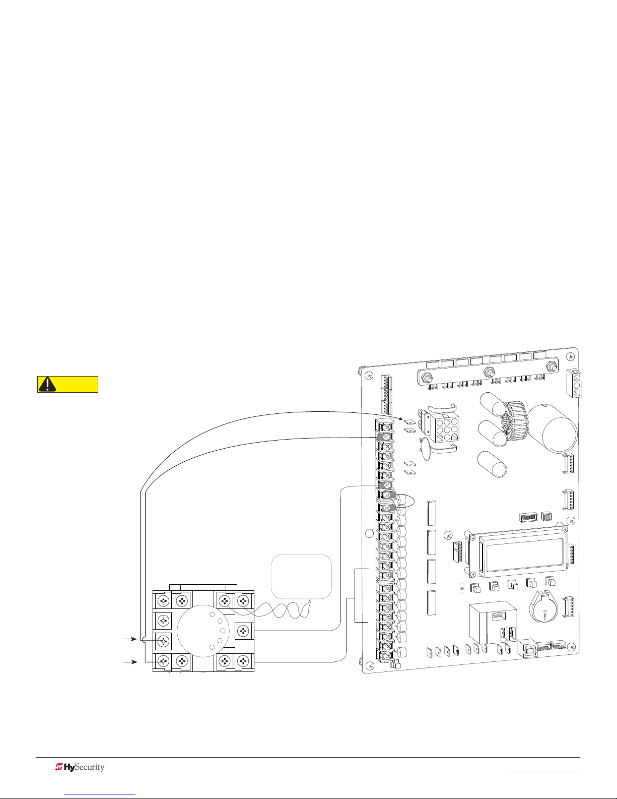
InstallIng standard 11-pIn Box tYpe veHICle deteCtors
If standard 11-pin box type vehicle detectors are to be used, perform the following procedure.
If there is sufcient space, install the sockets in the control box; if not, then install them in a separate external
housing. Carefully consider your peripheral connections. Any peripheral device required for safe gate
operation should be attached to 24VDC in case of an AC power outage.
NOTE: Box detectors with relays require ve times more power than Hy5x detectors. One Hy5x detector draws about 0.005A.
Consider Hy5x vehicle detectors for DC and Solar powered sites.
1. Connect 24 Volt power to the detector. Connect Pin No. 1 to a 24VAC or 24VDC terminal and Pin No. 2
to common.
2. Connect output Pin No. 6 to the Common Bus and output Pin No. 5 to one of the four detector
terminal inputs (depending upon the detector function required) on the Smart DC Controller.
If multiple detectors are used, route the power wires and common wire from socket to socket (daisy-chaining)
rather than individually running each wire to the same location. The only wires that are separate are the output
wire to the Smart DC Controller and the detector loop input wires.
Always keep the detector loop wires well twisted beyond the area of the loop. The lead in portion sealed in a
saw cut does not need to be twisted so long as the wires are encapsulated in loop sealant and cannot move.
CAUTION
Match detector connection to its
voltage rating (24VAC or 24VDC).
(+24V)
Pin 1
Pin 2
Loop
Detector
VEHICLE LOOP
To LOOP terminal on Smart
Touch Controller
COM
COM
COM
COM
COM
COM
COM
COM
STOP
OPEN
CLOSE
RADIO
OPEN
PARTIAL
SENSOR 1
SENSOR 3
EXIT
LOOP
BLOCK
EXIT
IN OBS
LOOP
OUT OBS
LOOP
CENTER
LOOP
SENSOR 2
SENSOR
COM
+ 24 V
EMERG
OPEN
OPEN
SHOW
LEDs
24VDC
24VDC
12VDC
12VDC
USER RELAY 1
Electro-mechanical
C
2
D
ER
S
U
O
1
S
N
4V
M
2
O
+
C
N
PE
O
M
CO
B
A
M
CO
U
D
R
TE
GA
L
A
S
N
IO
PT
O
O
I
D
A
NOTE: Both 24 Volts AC and DC are available, so either detector voltage may be used. 24 VAC is not
available if the Gate Operator is equipped with the UPS option. 24 VAC is available at the spade
terminals on the lower left corner of our power supply (marked ACC); 24 VDC is available from the
Common and the +24 V spade terminals.
48 MX3650-01 Rev. D StrongArmPark DC Programming & Operations © 2017 www.hysecurity.com
Page 59

strongarmpark dC Center loop laYout
SECURE
PUBLIC
Uni- or Bi-directional Traffic Control
Vehicles must pass from one loop
to the next without loss of detection
Dimension “A” = 6 ft minimum to 10 feet
maximum (305 cm).
Dimension “B” = 2 ft min. to 4 feet max.
(61 to 122 cm) between loop and edge
of roadway, is recommended.
Dimension “C” = 4 ft min to 8 ft max
(122 to 244 cm). Vehicles must pass
from one loop to the next without
loss of detection.
Dimension “D” = 2.5 ft (76 cm) to help
mitigate tailgating, but may not detect
higher bed vehicles.
Dim D = 6 feet (183 cm) to detect higher
bed vehicles.
Dimension “E” = 10 to 12 feet (305 to
366 cm) if an access control device
is employed.
Dimension “F” = 2 foot minimum
clearance (61 cm).
CENTER
LOOP
INNER
ARMING
LOOP
(IALD)
OUTER
ARMING
LOOP
(OALD)
FREE EXIT
LOOP
(optional)
A
B
C
C
E
Optional access control
devices (card reader, etc.)
Align along 6 ft edge of the
Outer Arming Loop.
F
x
H
Inductance Field created
when Loop is active.
Effective height of loop (H)
is 2/3 the distance of X.
To detect higher bed vehicles,
keep the short side at 6 ft (183 cm)
which creates a 4 ft (122 cm)
inductance field above ground.
If tailgating is a concern, a
smaller loop is needed, but it
may not detect high bed vehicles.
Vehicle Loop: Active
F
D
www.hysecurity.com © 2017 Vehicle Detector Installation and Loop Layouts MX3650-01 Rev. D 49
Page 60
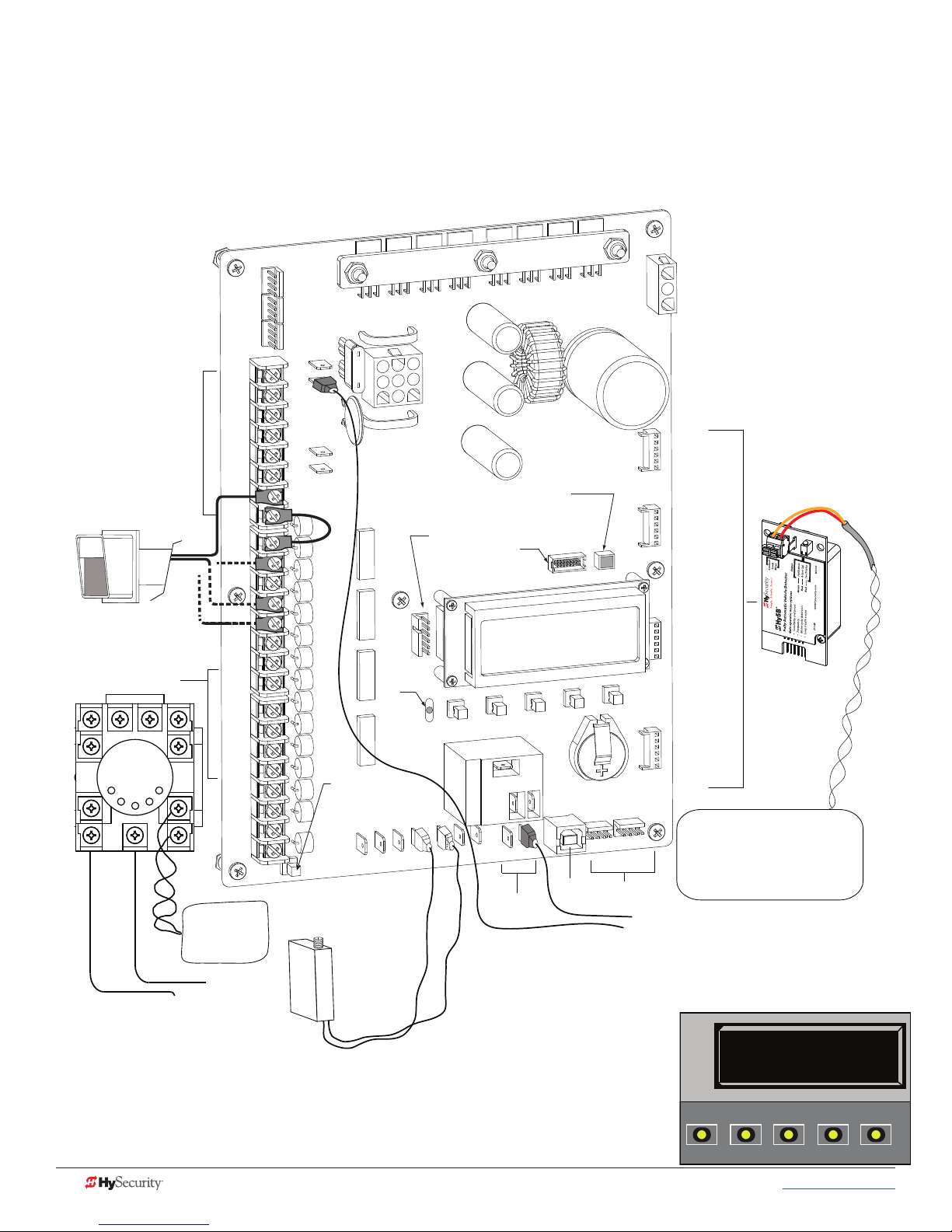
strongarmpark dC Center loop ConfIguratIon
Two different types of vehicle loop connections are shown in the illustration:
• Hy5x - HySecurity vehicle detector (see Table 4: Installer Menu on page 25 for more information).
• Generic box detector
COMMON
TERMINALS
Access controls
(Ex. Card reader, keypad)
Box Detector
Loop Detector
COM
COM
COM
COM
COM
COM
COM
COM
STOP
OPEN
CLOSE
RADIO
OPEN
PARTIAL
SENSOR 1
SENSOR 3
EXIT
LOOP
BLOCK
EXIT
IN OBS
LOOP
OUT OBS
LOOP
CENTER
LOOP
SENSOR 2
SENSOR
COM
+ 24 V
EMERG
OPEN
VEHICLE LOOP
24VDC
24VDC
12VDC
12VDC
OPEN
SHOW
LEDs
Radio receiver
Red LED
heart
beat
indicates
processor is
working.
A
M
O
C
A
G
AL
U
D
EXIT LOOP
indicates power and gate
status.
RS-232
OP
M
O
C
B
R
E
T
USER RELAY 1
Electro-mechanical
24V
+
EN
OPT
O
I
D
A
Ethernet
expansion
D
R2
E
S
U
1
S
O
C
S
N
IO
USER RELAY 2
Solid state
C
O
N
M
USB PORT
RS-485
COMMUNICATION
INSIDE LOOP
(Inner Arming
Loop)
OUTSIDE LOOP
(Outer Arming
Loop)
CENTER LOOP
LOOP
Not to Scale
Hy5B
Common
To LOOP terminal on Smart DC Controller
If you have a simple set up, similar to the single center loop diagram on page
7-3, you can change the default from re-opening if the center loop is triggered
to only pause when triggered. Closure continues as soon as the loop is clear
again. See the “CR” menu item in the Table 4: Installer Menu on page 25.
50 MX3650-01 Rev. D StrongArmPark DC Programming & Operations © 2017 www.hysecurity.com
CR 0 REVERSE
CENTER LOOP
CLOSE
OPEN
NEXT
PREV
STOP
SELECT
MENU
RESET
Page 61
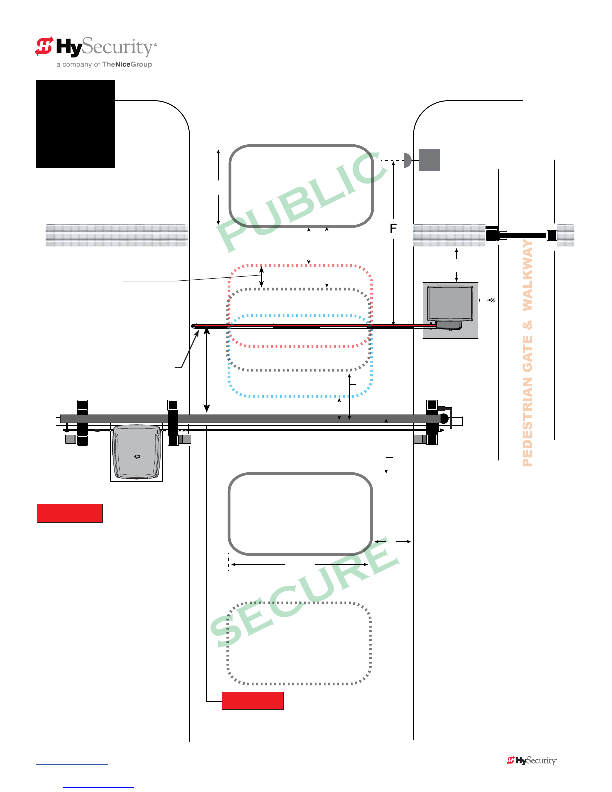
SECURE
PUBLIC
sequenCed gates #1: loop laYout
StrongArmPark DC Loop Layout
1
To sequence the gates, set the
Installer Menu item, SG to “1” in
both gate operators.*
Operator & Loops**
As trafc control and security gates
are separated farther apart, adjust
Center Loop toward centerline of
the Trafc Control Gate.
TRAFFIC CONTROL GATE
StrongArmPark DC (Trafc Control Gate)
with SlideSmart DC (Security Gate)
OUTER ARMING LOOP
D
(OALD for Trafc Control Gate
Not used by Security Gate)
(OALD)
F
E
CENTER LOOP
Loop can be offset from
C/L of barrier arm 1 to 5 ft
(31 to 152 cm)
(OALD for Security Gate)
C
Optional access control
devices (card reader, etc.).
Align along 6 ft edge of the
Outside Obstruction Loop.
Location changes depending on
uni- or bi-directional trafc.
Minimum 2 ft (61 cm)
*NOTICE
For sequenced gates to operate
properly, all vehicle detectors
must be wired to the Trafc
Control Gate.
If a communication failure occurs,
an AL22 (Alert 22) appears and the
buzzer sounds. The Trafc Control
Gate maintains functionality
whilethe Security Gate defaults
to open until communication is
restored (or the Security Gate is
manually closed).
Drawings not to scale.
INNER ARMING LOOP
(IALD)
IALD for Trafc Control Gate.
IOLD for Security Gate. Or, Free Exit
for both operators. If loop used as Free
Exit, you must have an OALD loop.
A
FREE EXIT LOOP
(optional)
**NOTICE
Center to center between gates:
4 ft minimum (122 cm)
9 ft maximum (274 cm)
B
C
Uni- or Bi-directional Trafc Control
Vehicles must pass from one loop to
the next without loss of detection.
Dimension “A” = 6 ft minimum to 12 ft
maximum (183 to 366 cm).
Dimension “B” = 2 ft minimum to 3 ft
maximum (61 to 91 cm).
Dimension “C” = 3 ft min. to 4 ft max.
Distance from edge of Center Loop to
C/L of the Security Gate is 3 to 4 ft.
Dimension “D” = 6 ft (183 cm).
Dimension “E” =
244 cm)
from C/L of gate: 1 to 5 ft (31 to 152 cm).
Dimension “F” =
max. Center Loop can be offset
4 ft min. to 8 ft (122 to
10 to 15 feet (3 to 3.6 m)
www.hysecurity.com © 2017 Vehicle Detector Installation and Loop Layouts MX3650-01 Rev. D 51
Page 62
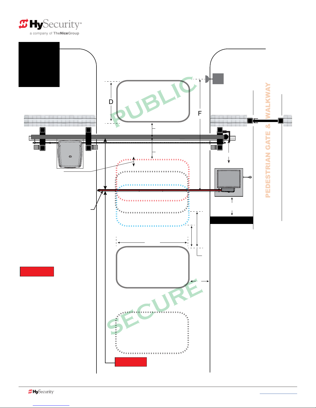
SECURE
PUBLIC
sequenCed gates #2: loop laYout
StrongArmPark DC Loop Layout
2
To sequence the gates, set the
Installer Menu item, SG to “2” in
both gate operators.*
Operator & Loops**
As trafc control and security gates
are separated farther apart, Center
Loop moves toward centering under
the Trafc Control Gate.
TRAFFIC CONTROL GATE
StrongArmPark DC (Trafc Control Gate)
with SlideSmart DC (Security Gate)
OUTER ARMING LOOP
D
(OOLD for Security Gate)
(OALD)
F
C
SECURITY SLIDE GATE
C
SECURITY SLIDE GATE
CENTER LOOP
Loop can be offset from
C/L of barrier arm 1 to 5 ft
(31 to 152 cm)
Optional access control
devices (card reader, etc.).
Align along 6 ft edge of the
Outside Obstruction Loop.
Location changes depending on
uni- or bi-directional trafc.
Minimum 2 ft (61 cm)
Minimum 2 ft (61 cm)
*NOTICE
For sequenced gates to operate
properly, all vehicle detectors
must be wired to the Trafc
Control Gate.
If a communication failure occurs,
an AL22 (Alert 22) appears and the
buzzer sounds. The Trafc Control
Gate maintains functionality
whilethe Security Gate defaults
to open until communication is
restored (or the Security Gate is
manually closed).
Drawings not to scale.
(IOLD for Security Gate)
A
INNER ARMING LOOP
(IALD)
IALD for Trafc Control Gate or
Free Exit for both operators. If
loop used as Free Exit, you must
have an OALD loop.
FREE EXIT LOOP
(optional)
**NOTICE
Center to center between gates:
4 ft minimum (122 cm)
9 ft maximum (274 cm)
B
Uni- or Bi-directional Trafc Control
E
Vehicles must pass from one loop to
the next without loss of detection.
Dimension “A” = 6 ft minimum to 12 ft
maximum (183 to 366 cm).
Dimension “B” = 2 ft minimum to 3 ft
maximum (61 to 91 cm).
Dimension “C” = 3 ft min. to 4 ft max.
Distance from edge of Center Loop to
C/L of the Security Gate is 3 to 4 ft.
Dimension “D” = 6 ft (183 cm).
Dimension “E” =
244 cm)
from C/L of gate: 1 to 5 ft (31 to 152 cm).
Dimension “F” =
max. Center Loop can be offset
4 ft min. to 8 ft (122 to
10 to 15 feet (3 to 3.6 m)
52 MX3650-01 Rev. D StrongArmPark DC Programming & Operations © 2017 www.hysecurity.com
Page 63

Photo Eye Installation
A monitored connection tests for the presence and correct operation of the photo eyes (and other monitored
sensors) prior to each gate activation. The monitored connection prevents gate operation if an entrapment
protection sensor is missing or any fault is present.
Sensors, such as gate edges and photoelectric beams, must be installed to protect against entrapment. These
external entrapment protection sensors are required for the gate installation to be in compliance with the
2016, UL 325 Standard of Safety (6th Edition).
NOTICE: UL 325 Standard of Safety provides the MINIMUM safety standards. Site, gate hardware usage,
and other conditions may dictate the use of additional safety designs/components. It is up to the gate system
designer and installer to assess appropriate safety design and components above and beyond minimum UL 325
and ASTM F2200 Standard of Safety. Always check your local area codes and comply with all regulations.
NOTE: Visit www.hysecurity.com/gatesafety for more information on UL 325 standards and gate safety.
To learn more about external entrapment protection devices or to learn how to temporarily supply power to
the sensors that are wired to the gate operator, review External Entrapment Protection Sensors monitored by
HySecurity Gate Operators on page 9 .
For barrier arm gates, see Table 2: HySecurity Gate Operators maintaining Object Detection on page 8.
www.hysecurity.com © 2017 Photo Eye Installation MX3650-01 Rev. D 53
Page 64

pHoto eYes (non-ContaCt) InstallatIon
Plan to integrate photo eyes (photoelectric sensors) in your site plan. Photo eyes are wired to the Controller
and require low voltage conduit to the operator and power supply. Refer to External Entrapment Protection
Sensors monitored by HySecurity Gate Operators on page 9.
Understand your site requirements and use the layout diagrams available to determine the most appropriate
mounting positions for additional photo eyes. The Controller has three sensor inputs.
If there are no other external entrapment protection sensors, then for slide gates, swing gates or any site that
must comply with UL 325 monitored entrapment protection regulations, it is highly recommended that at
least two photo eyes are installed to serve and reverse the gate in each direction of travel (Open and Close
directions).
The two common photoelectric sensor types are thru-beam and retro-reective; each has its advantages.
• A thru-beam sensor is generally more powerful and able to function more reliably in inclement
weather.
• A retro-reective sensor (generally less reliable in inclement weather or low visibility) provides
convenience due to minimal wiring.
NOTE: In an outdoor environment (because of reduced performance), avoid using a retro-reective sensor to
span a distance greater than 24 feet (7.3 meters).
Compatibility
The UL 325 standard requires that a photoelectric sensor be laboratory tested and “recognized” under UL 325.
In order to be compatible with all HySecurity operators, a photo eye must be rated to function from 24 VDC
source power.
A list of tested and approved external entrapment protection sensors (normally closed contacts) that are
compatible with HySecurity gate operators can be found online at the following public site: Gate Safety for
HySecurity Gate Operators.
Installation
Install photo eyes according to the following steps.
1. Locate the photo eye in line of sight to the receiver or reector that is mounted to protect zones of
potential entrapment.
2. Mount the receivers on the left or right side of the gate operator.
3. Mount the emitters just beyond the travel of the gate.
NOTE: The installation locations are intended for pedestrian detection. If photo eyes are also to be used for
vehicular detection, consider (in addition to the low elevation photo eye for cars) installing another photo eye
at a height of about 55 inches (140 cm) to detect semi (tractor- trailer) trucks.
54 MX3650-01 Rev. D StrongArmParkDC Programming & Operations © 2017 www.hysecurity.com
Page 65

Configuration
CAUTION
Congure photo eyes attached to gate operators manufactured in 2016 or beyond according to UL 325 –
Monitored Entrapment Wiring Diagrams.
NOTE: HySecurity gate operators, manufactured with 2016 (or later) in the serial number, require Normally Closed output sensors.
Some manufacturers label an output as N.O. (normally open), when it is actually an N.C. (normally closed) contact. Review External
Entrapment Protection Sensors monitored by HySecurity Gate Operators on page 9.
If your gate operator is manufactured prior to 2016 and/or your gate operator is set to Build
Year 1, consider the following:
NOTE: To check the Build Year for your gate operator, press the Menu button. The gate status scroll reveals
the Build Year. “Build Year Pre-2016” means the gate operator is congured for Build Year 1.
1. If the photo eye has an internal switch for setting Light Operate versus Dark
Operate, select Light Operate.
2. If the photo eye has a relay output and has both N.O. and N.C. terminals, some
experimentation may be required to determine the proper connection because,
when its in the Light Operate mode, the output relay is normally energized and
releases when the beam is blocked.
3. If the photo eye has a solid-state output, your must choose a sinking-type connection.
Photo Eye Connections: Smart Touch & Smart DC Controllers
All external entrapment protection sensors must be NC sensor outputs and wired to the SENSOR COM terminal for
monitoring and powering purposes. The sensor becomes actively powered when the gate operator’s motor runs.
Connect the four wires to the receiver and two wires to the emitter according to the following procedure.
A. Supply power to the sensor.
1. Find the +24V spade-terminals inside the inputs edge or use +24V from RADIO OPTIONS located at
the base of the SDC Controller. (If connecting to STC, obtain the +24 Volt source power at one of the
three spade-terminals on the STC Power Supply Board. )
2. Obtain the 24 Volt Common from SENSOR COM on the Controller.
B. Wire connection so the controller recognizes the sensor device.
3. For the relay output, obtain the COM along the SDC inputs edge (or from the STC Power Supply Board
on an STC).
4. Connect the N.C. output to SENSOR 1, 2, or 3.
5. Congure the Installer Menu according to your site device set up. Refer to UL 325 – 2016, Monitored
Entrapment Wiring Diagrams.
NOTE: Jumper between terminals on Photo Eye sensor so you don’t need to pull a fourth wire to the Controller terminal.
Photo Eye Function
If the gate is stationary, a tripped photo eye will prevent the gate from starting in either direction. If tripped
while in motion, the standard function is to pause the gate motion and then automatically restart again if the
photo eye is clear within ve seconds. Optional settings exist in the Installer Menu. Refer to Eye Close Logic
and Eye Open Logic (EC and EO) in Table 4: Installer Menu on page 25 for more information.
www.hysecurity.com © 2017 Photo Eye Installation MX3650-01 Rev. D 55
Page 66

retro-refleCtIVe PHoto eye SyStemS
Correct installation and alignment of a retro-reective photo eye and its reector is important for trouble free
performance. Any system operating at a range greater than 16 feet is more prone to false triggering due to
dirty optics, condensation or poor weather. If care is taken in the initial mounting and alignment of the 3-inch
reector, the chance of problems is greatly reduced.
NOTE: Use only through beam photo eyes for a distances greater than 24 feet because the function of a retro-reective photo eye
will be too unreliable.
Taking steps to protect the photo eye and the reector from being exposed to fog and being absolutely
certain the photo eye is perfectly aligned will greatly reduce any false triggering of the system. The ideal
mounting of a retro-reective photo eye is inside an enclosure.
Ideally the reector mount suspends the reector inside a 12-inch long piece of 3-inch PVC conduit. Cut
the opening of the PVC conduit at a 45-degree angle to act as a drip shield. Hold the reector against the
backside of the PVC conduit by attaching a 3-inch male connector.
it difcult to reach the reector for future cleaning.
To create a mounting base, attach a 3-inch aluminum ange (for example, an electric meter hub) to the
connector. This whole package can be mounted to any at surface.
Locate the reector in the center of the invisible beam of infrared light to achieve the most sensitive alignment.
DO NOT cement the connector as doing so makes
The beam center is determined by the following test:
1. While holding the reector in your hand, slowly raise it until the beam is no longer returned and the
photo eye trips.
2. Mark this maximum height.
3. Lower your hand and determine the lower limit of the infrared beam by watching for the trip point.
Mark this position.
4. Repeat the same procedure for left and right at the center elevation of the beam.
When the four parameters are marked, either:
• Mount the reector in the center of the area outlined
or
• Realign the eye for the position of the reector.
NOTE: If the photo eye is realigned, be sure to perform the centering test again to verify that the reector is truly in the center.
56 MX3650-01 Rev. D StrongArmParkDC Programming & Operations © 2017 www.hysecurity.com
Page 67

pHoto eYe alIgnment feature
Most photo eyes require careful optical alignment in order to aim the emitter beam to the center of the
receiver or reector. In order to avoid false triggering, it is important to carefully align the system.
Align the photo eyes using this feature by taking the following steps:
1. Access the User Menu and select PE.
To access the User Menu, press the Menu button twice. For a
refresher on using the Menu Mode navigational buttons, refer to the
chart below.
PE 1 (ON)
PHOTO EYE ALIGN
CLOSE
OPEN
STOP
MENU
RESET
2. Press NEXT and continue to press NEXT until PE 0 (OFF) appears.
PREV
NEXT
SELECT
3. Press SELECT.
PE characters begin blinking.
4. To turn ON photo eye alignment and temporarily power the sensors, press NEXT so PE 1 (ON) appears.
5. Press SELECT.
PE stops blinking.
6. Move the photo eyes (up/down, side to side) to align the emitter beam.
Audible Chirp Beam Aligned ??
One No
Two Yes
7. When the buzzer chirps twice, indicating the photo eyes are aligned, set the next photo eye (if the site
has one) and continue the process until all photo eyes are aligned.
8. Press MENU to exit Menu Mode and return to Run Mode.
9. Move the gate with an open or close command. When a limit is triggered, the User Menu item PE
resets to zero (OFF).
Smart DC Controller: Menu Mode Navigation Buttons
To access
Menu mode
Press the Menu button
twice.
To change menu item
appearing in the display
Press Select.
Two left characters blink.
To navigate through
the menu item selections
Press Next or Previous.
Continue pressing Next to view all
selections.
To choose what item appears
on the display
Press Select.
Blinking characters
become static.
To navigate between
menu items
Press Next or Previous.
Advance - press Next
Previous - press Previous
www.hysecurity.com © 2017 Photo Eye Installation MX3650-01 Rev. D 57
Page 68

Page intentionally left blank
58 MX3650-01 Rev. D StrongArmParkDC Programming & Operations © 2017 www.hysecurity.com
Page 69

Troubleshooting
The Smart DC Controller reports system malfunctions using three simultaneously occurring methods:
• Codes presented on its display (alert, fault or error)
• Activation of a buzzer which emits a series of chirps at dened
interval
!ACTION BLOCKED
PHOTO EYE CLOSE
• Gate travel stops
Refer to Table 3, Table 8: Troubleshooting Codes on page 60, for details
concerning identication and description of Alerts, Faults and Errors.
To help in problem-solving, the active status of each input on the controller
is indicated by its associated LED.
• On AC-powered gate operators: Active-input LEDs are always
illuminated.
• On solar-powered gate operators (with input power OFF): Press
and hold the Tact button to illuminate the active-input LEDs.
NOTE: A qualied technician may troubleshoot the operator with the aid of the
information and procedures that follow. If it is necessary to call a distributor for
assistance, be sure to have the model and serial numbers available. Other helpful information is the job name,
approximate installation date, and service and records of any recently-performed maintenance work.
sYstem dIagnostIC messages
Code Priority How to clear
ALERT Low Enter a new command such as Open or Close.
FAULT Medium Press the Stop or Reset button
High
ERROR
Serious issue that may require
Technical Support.
Errors can only be cleared by pushing the Reset button or cycling power.
CLOSE
OPEN
NEXT
PREV
ALERT 17
BAD COIN BATTERY
CLOSE
OPEN
NEXT
PREV
STOP
SELECT
STOP
SELECT
MENU
MENU
RESET
RESET
NOTE: The green LED near the display on the Smart DC Controller is the “fault indicator” of the processor. A steady green LED
indicates the system is receiving power and operating in Run mode. When a fault, error, or alert occurs, it turns RED. A yellow LED
indicates Menu mode.
The Smart DC Controller maintains self-diagnostics. Specic codes appear on the display and the Audio Alert
buzzer emits distinctive chirping sounds. Any Alert, Fault, or Error is logged into memory and stamped with
the date and time. These diagnostic messages can be retrieved for analysis purposes via optional PC-based
S.T.A.R.T. software or through the Event Log if your operator is using software version h5.52 or higher. Refer to
Access the Event Log through the User Menu on page 67.
NOTE: S.T.A.R.T. conguration and diagnostic software is available at no charge from www.hysecurity.com. Schedule software
updates as part of routine maintenance. Refer to General Maintenance section.
www.hysecurity.com © 2017 Troubleshooting MX3650-01 Rev. D 59
Page 70

Table 8: Troubleshooting Codes
Table 8: Troubleshooting Codes
Alert/Fault/Error
Display
ENTRAPMENT MODE ALERT 4 to 5
SAFE MODE ALERT Occurs when either the edge sensor
NO AC POWER ALERT Chirps
LOW 24VDC ALERT Flashes on
DEAD BATTERY ALERT 3 chirps
HYSECURITY
BAD POWER
Type Buzzer Possible Cause Suggested Corrective Action
Occurs when the inherent sensor is tripped
chirps/s for
5 minutes
or until
cleared
once
whenever
the gate
reaches
the close
limit
display 1s
every 5s
upon any
operating
command
entry
ALERT N/A Critically low 24V supply power. DC Buss
when the gate is already in Safe Mode. The
operator will not function until it is reset,
which can occur by:
• An Open or Stop command
• A Reset button command or a Fire
Open command.
With any one of these inputs, the operator
will return to Safe Mode. Barrier arm
binding or wind can cause a false alert.
or inherent sensor has been tripped. In
Safe Mode, the automatic close timer is
disabled, but any command will reset and/
or start the gate in motion. Safe Mode
clears when full travel is reached or the
RESET button is pressed. Note that too
tight of a spring on the DC14, hardware
binding, or wind can cause a false alert.
AC power is shut off at the source (breaker)
or is not connected. The AC power switch
on the operator (lower rocker switch) is
turned off, or the circuit breaker on the
operator has tripped.
Occurs when the battery voltage has
dropped to less than 22 Volts. At this level,
the batteries are 80% depleted.
NOTE: Functionality of the controller
board becomes impaired when the voltage
drops below 21 Volts.
Extremely low UPS batteries – no
automatic operation - batteries below 21
Volts. At this level, the batteries are 90%
depleted. The gate will automatically
open or close depending upon the setting
chosen. Gate movement is possible,
but limited to push button control until
batteries reach 18 V.
power is below 14V – no control functions
will be allowed. This message can occur
only on initial start up, if power is critically
low.
1. Remove the obstruction.
2. Correct the gate hardware or
temporarily, remove the arm in
high wind conditions.
1. Remove the obstruction.
2. Correct the gate hardware.
3. Adjust spring tension on a
StrongArmPark DC14
1. Have a licensed electrician check
the wiring.
2. Connect AC power to the
operator.
3. Reset circuit breaker at electrical
panel. Reset the operator circuit
breaker.
4. Turn AC power switch on.
1. No AC Power. See above item.
2. Check all wiring connections.
Clean or repair as required.
3. Check the following and replace,
if necessary:
• Battery condition
• Charger failure. Check charger
voltage
• SDC
• Transformer
See corrective action above.
See corrective action above.
60 MX3650-01 Rev. D StrongArmPark DC Programming & Operations © 2017 www.hysecurity.com
Page 71

Table 8: Troubleshooting Codes
Alert/Fault/Error
Display
Type Buzzer Possible Cause Suggested Corrective Action
No display, LED blinks ALERT Smart DC Controller is receiving power,
but battery voltage is very low.
Several possible causes:
• The AC power has been shut off from
the operator for too long and the
batteries are drained.
• Wiring problem.
• Batteries no longer hold a charge.
• The Smart DC Controller failed.
• Bad transformer.
HYSECURITY
ALERT Software is currently being loaded. Wait for software to nish loading.
LOADER
FORCE OPEN ALERT 1 2 chirps/s
for 30s
The gate has been forced open from a full
close limit and is being prevented from
re-closing.
DRIFT CLOSED ALERT 2 2 chirps/s
for 10
seconds
The gate has drifted closed from a full
open limit and is being prevented from
re-opening.
EXCESS DRIFT ALERT 3 Gate drift in transit - Advisory only. The
alert appears if the gate drifts three times
in a ve minute period.
MOTOR OVERLOAD ALERT 4 2 chirps/s
every 15
seconds
Thermal overload alert. Motor drive
heat sink exceeds 210°F. When the alert
is triggered, the gate can only “fully
open” until the alert is cleared. The alert
temporarily disables the operator.
BOTH LIM ACTIVE ALERT 5 2 chirps/s
every 15
seconds
Both limit switches are on at the same
time. Possible causes:
• Short in wiring
• Stuck limit switch
• Debris in limit plate area (SwingSmart)
LIM NOT RELEASED ALERT 6 2 chirps/s
every 15
seconds
The limit did not release when the
operator was commanded to move.
Possible causes:
• Broken drive belt.
• Hardware holding the arm.
FREQ SHIFT FAULT ALERT 7 2 chirps/s
every 15
seconds
An Hy5x vehicle detector: Abnormal
frequency change alert. Likely causes are
poor integrity of loops or metallic objects
within range. The display indicates which
detector the alert applies to: Exit Loop
(ELD), Inside Arming Loop (IALD), Outside
Arming Loop (OALD), Center Loop (CLD).
LOOP SHORTED ALERT 8 2 chirps/s
every 15s
LOOP OPEN ALERT 9 2 chirps/s
every 15s
An Hy5x vehicle detector: Loop is shorted.
Inadequate insulation of loop wires.
An Hy5x vehicle detector:
Disconnected loop alert.
Lack of continuity in the loop wire possibly
caused by broken loop wire or wire
unplugged from detector.
See corrective action above.
Will self-clear after an open or close
input.
Will self-clear after an open or close
input.
High wind factor: Remove arm or
open gate.
Slide gates: Check the track to
make sure it is level.
1. Check gate hardware.
2. Check for properly sized weight/
length of gate/arm.
Alert automatically clears when the
temperature drops below threshold.
The SDC is seeing both limits
tripped at the same time.
Repair any wiring issues.
• Check/replace drive belt.
• Release any holds on the arm.
• Relearn Limits.
Check the loop, lead in wires, and
roadway for problems. Replace
them, if needed.
Temporarily switch detector to be
sure the loop is at fault, and then
repair it.
The loop and lead in wires should
be checked for problems or
replaced.
www.hysecurity.com © 2017 Troubleshooting MX3650-01 Rev. D 61
Page 72

Table 8: Troubleshooting Codes
Alert/Fault/Error
Display
I²C BUS ERROR ALERT 10 2 chirps/s
DETECTOR FAULT ALERT 11 2 chirps/s
Type Buzzer Possible Cause Suggested Corrective Action
Remove and re-install the Hy5x and
press RESET. Replace the Hy5x, if
necessary.
If communication is not re-
established within 30 seconds,
the controller will reset and the
message changes to
ERROR 3.
Remove and re-install the Hy5x and
press RESET. Replace the Hy5x, if
necessary.
every 15s
every 15s
An Hy5x vehicle detector:
Communications error alert.
Hy5x has been removed or there’s a lack
of integrity of the socket connection.
The display indicates which detector the
alert applies to: Exit Loop (ELD), Inside
Arming Loop (IALD), Outside Arming Loop
(OALD), Center Loop (CLD).
An Hy5x vehicle detector: Malfunction
alert Caused by a fault within the Hy5x.
The display indicates which detector the
alert applies to: Exit Loop (ELD), Inside
Arming Loop (IALD), Outside Arming Loop
(OALD), Center Loop (CLD).
ON TOO LONG ALERT 12 2 chirps/s
every 15s
The Smart DC Controller has an active
loop input (Hy5x or box detector output)
for more than 5 minutes. The SDC “sees”
an active loop for more than 5 minutes.
The “active” loop can be actual or false.
The display indicates which detector the
alert applies to: Exit Loop (ELD), Inside
Arming Loop (IALD), Outside Arming Loop
(OALD), Center Loop (CLD).
1. Check trafc patterns at the site
and make sure that a vehicle is
not parked on the loop.
2. Determine if the loop is stable.
An unstable loop can hold the
detector in a triggered state.
3. The loop and lead in wires
should be checked for problems
and replaced, if necessary.
4. Check sensitivity setting on the
detector.
STIFF GATE ALERT 13 2 chirps/s
every 15s
The SDC detects a gate that, over time, is
requiring more power to move it. Usually
caused by degrading gate hardware
or debris in a slide gate track, this alert
1. Check and correct gate hardware
as required.
2. Check motor brushes for
excessive wear.
appears in the history log. It does not
affect opening or closing the gate.
STUCK GATE ALERT 14 2 chirps/s
every 15s
The SDC detects that it cannot move the
gate at all possibly caused by broken gate
hardware or ice/snow buildup.
1. Manually move the gate. Verify
that it moves easily and is
unobstructed throughout gate
travel.
2. Check and correct gate
hardware, as required.
NO TARGET ALERT 15 2 chirps/s
every 15s
The target magnet on the StrongArmPark
DC or on the chain (SlideSmart DC) is
missing or has not been detected.
1. Make sure target is properly
fastened. Did you move it or
unscrew it? Is the target magnet
or wires to it, broken?
2. Red LED light ashes in
the upper left corner of the
controller when it senses the
target. Did the red LED light
ash while opening or closing
the gate? If not, target is missing.
BAD COIN BATTERY ALERT 17 3 chirps
at initial
power up
The small battery on the SDC is loose or
needs replacing.
1. Check for current software,
install update, if necessary.
2. Verify that the battery is properly
seated.
3. Replace coin battery.
4. Restore power.
5. Press RESET button.
62 MX3650-01 Rev. D StrongArmPark DC Programming & Operations © 2017 www.hysecurity.com
Page 73

Alert/Fault/Error
Display
Type Buzzer Possible Cause Suggested Corrective Action
CHANGE BATTERY ALERT 18 1 chirp a
minute
INTLOCK FAILURE ALERT 22 2 chirps/s
every 15
seconds
EXT RELAY FAULT ALERT 24 2 chirps/s
every 15
seconds
MOTOR RUN TIME FAULT 1 1 chirp
every 15s
Table 8: Troubleshooting Codes
Batteries are not taking a charge properly.
The SDC has detected that the 24VDC UPS
batteries need to be replaced.
Interlock/Sequenced Gate communication
lost. Appears when the RS-485
communication connection is lost for more
than 15s between interlocked (dual gate)
or sequenced gate operators.
Communication issue exists.
The extended relay module, Hy8Relay,
is not being recognized or it is not
connected and values exist in the
extended relay menu items. Alert noted in
diagnostic log.
NOTE: Keep your HySecurity gate
operators current by “uninstalling”
outdated versions of the S.T.A.R.T.
application. Be aware that the current
operator software code is not compatible
with older version of S.T.A.R.T. nd the
latest software and operator code at
www.hysecurity.com
The Smart DC Controller has detected
the motor is on longer than the maximum
run time selected. Should not occur in
StrongArmPark DC.
Replace the batteries. (The buzzer
will chirp every minute until the UPS
batteries are replaced.)
1. Check cable connections and
wiring. Make sure both operators
are working properly and have
the same current and up-to-
date software versions. The
alert automatically clears when
communication between the two
operators is restored.
2. Verify operators are congured
correctly. For example, if the
operator on site is a solo gate
operator and the display code
ALERT 22 appears, access the
Installer Menu.
3. Verify the Installer Menu
items: DG (Dual Gate) and SG
(Sequenced Gate) are both set
to zero. If gates are interlocked,
make sure the DG and SG
settings are correct.
4. Upload correct S.T.A.R.T.
software and operator code.
Check the wiring:
1. Make sure the slide switch on
the side of the extended relay
module is set at “Normal.”
2. (Y) Data + is connected to “A”
DUAL GATE.
3. (G) DATA - is connected to DUAL
GATE.
4. Connector cable (4-Pin) attaches
to RS-485.
If the Hy8Relay module is not
connected, access the Installer
menu and check that the extended
relays are set to zero. SDC relays =
R3 to R10.
1. Check and replace drive belt.
2. Increase Max Run Timer in the
Installer Menu.
PHOTO EYE FAULT 2 2 chirps/s
once per
minute
www.hysecurity.com © 2017 Troubleshooting MX3650-01 Rev. D 63
Possible causes:
• Broken drive belt
• Taper clamp slipping (SwingSmart)
The photo eye is missing or not working.
This fault can only occur if the supervised
photo eye function is enabled in the
Installer Menu.
Correct malfunctioning photo eye.
Page 74

Table 8: Troubleshooting Codes
Alert/Fault/Error
Display
GATE NO LOAD FAULT 4 2 chirps/s
Type Buzzer Possible Cause Suggested Corrective Action
The Smart DC Controller detects there is
once per
minute
no load on the operator. The gate is not
operational while this fault is triggered.
Several possible causes:
• DC switch off
• Motor wires disconnected
LIMIT FAILED FAULT 5 Not used in StrongArmPark DC.
STUCK GATE FAULT 14 2 chirps/s
once per
minute
The Smart DC Controller has tried 3 times
to overcome a stuck gate/arm. The gate/
arm is non-operational while this fault is
triggered. Caused by broken gate/arm
hardware or ice/snow buildup.
DIRECTION ERROR ERROR 1 3 chirps/s
once per
minute
The Smart DC Controller detects that the
operator ran in the wrong direction.
Possible causes:
• Motor wiring
• Limit switch wiring (SwingSmart)
1 chirp
indicates
command
!ACTION BLOCKED
PHOTO EYE CLOSE
Photo Eye
Close
cannot be
initiated
1 chirp
indicates
command
!ACTION BLOCKED
PHOTO EYE OPEN
Photo Eye
Open
cannot be
initiated
1 chirp
!ACTION BLOCKED
GATE EDGE
Gate
Edge
Sensor
indicates
command
cannot be
initiated
HY-5x FAILED ERROR 3 3 chirps/s
once per
minute
Operator received command to run, but
movement is prevented. Photo eye is
blocked or battery is dead.
Operator received command to run, but
movement is prevented. Photo eye is
blocked or battery is dead.
Operator received command to run,
but movement is prevented. Gate edge
blocked or disconnected. If tripped when
gate is moving, causes operator to enter
SAFE mode.
Hy5x communication failure.
Caused by removal of Hy5x or lack of
integrity of the socket connection. The
display indicates which detector the
alert applies to: Exit Loop (ELD), Inside
Obstruction Loop (IOLD/IALD), Outside
Obstruction Loop (OOLD/OALD), or
Center Loop (CLD).
1. Turn on DC power switch.
2. Replace drive belt.
3. Check DC motor wires.
4. Press RESET to clear fault.
1. Check and correct gate hardware
as required.
2. Press RESET to clear fault.
1. Check the following and correct,
as needed.
• Motor wiring
2. Press RESET to clear error.
1. Check the following and correct,
as needed.
• Photo eye path. Realign photo
eye.
User Menu:
PE1, PHOTO EYE ALIGN
• Photo eye battery
2. Press RESET to clear error.
1. Check the following and correct,
as needed.
• Photo eye path. Realign photo
eye.
User Menu:
PE1, PHOTO EYE ALIGN
• Photo eye battery
2. Press RESET to clear error.
1. Check the following and correct,
as needed.
• Obstructions, remove.
• Faulty edge sensor.
2. Press RESET to clear error.
1. Press RESET to clear error.
2. Remove and re-seat the Hy5x.
3. If needed, replace the Hy5x.
64 MX3650-01 Rev. D StrongArmPark DC Programming & Operations © 2017 www.hysecurity.com
Page 75

Alert/Fault/Error
Display
Type Buzzer Possible Cause Suggested Corrective Action
MASTER-SLAVE COM ERROR 4 3 chirps/s
once per
minute
No display ERROR 5 3 chirps/s
once per
minute
MENU CHECKSUM ERROR 7 2 chirps/s
every 15s
RPM SENSOR ERROR 8 3 chirps/s
once per
minute
BATT DISCONNECT ERROR 9 3 chirps/s
when
detected
Table 8: Troubleshooting Codes
The Smart DC Controller detects a
communication error between master and
slave in a dual gate installation. Several
possible causes:
• Master/Slave communication cable has
not been installed correctly.
• Master/Slave not congured properly
through the Installer Menu.
• Operator not properly earth grounded.
• Master/Slave communication cable
installed in same conduit as high-
voltage AC power.
• One operator does not have power
applied to it.
• One operator may have a different
software version.
The display provides no indication of this
error, but it can appear in the S.T.A.R.T. log
and means that the Smart DC Controller
has detected a serious internal error.
Software issue exists that may require
factory reset. Corrupt software or data.
RPM sensor disconnected. Motor Encoder
or wires are damaged or unplugged.
The Smart DC Controller cannot identify
battery connection. The batteries are
disconnected or a wiring fault exists.
Automatically resets after one minute.
1. Correct communication cable.
2. Verify that each operator is
congured properly through the
Installer Menu. One operator
must be set as Master and the
other as Slave using the Installer
Menu.
3. Install ground rod per NEC/
NFPA standard.
4. Install separate conduit for
communication cables.
5. Ensure AC power is present at
both operators and all power
switches are ON.
6. Check software version in
operators by pressing RESET.
Make sure both operators are
running the same software
version.
1. Report any instance of this error
to HySecurity Technical Support.
2. Turn both power switches off to
reset software.
3. Use S.T.A.R.T. to update the
operator to the most current
software version.
4. Replace Smart DC Controller.
Call HySecurity Technical Support
for assistance.
Check wiring from the motor to the
Smart DC Controller board.
Smart DC operators ship with a wire
disconnected to prevent battery
drain.
1. Ensure the red wire’s spade
connector in the upper left
corner of the control box is
plugged in.
2. Correct any issues with battery
wiring.
3. Check the 35 amp fuse on the
circuit board. If blown, replace
it.
www.hysecurity.com © 2017 Troubleshooting MX3650-01 Rev. D 65
Page 76
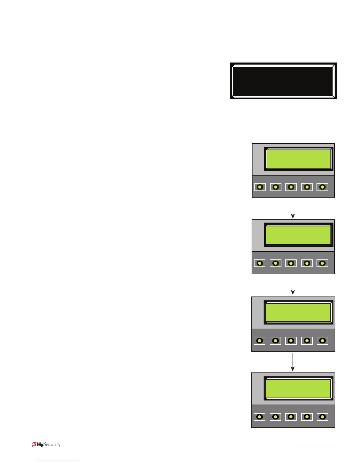
adjustIng tHe dYnamIC reversIng sensor
StrongArmPark DC uses a dynamic reversing sensor. A solid immovable object blocking the gate will trip the
sensor and cause the operator to stop, reverse and enter safe mode.
Available settings (0, 1, and 2), accessed through the Installer Menu,
allow you to adjust the level of sensitivity. A maximum sensitivity of
zero (0) is the default setting.
SE 0
IES SENSITIVITY
When changing the setting, consider the site design and vehicular
gate trafc. It is recommended that you use the most sensitive setting
while still allowing for reliable gate operation.
To adjust the sensitivity, take the following steps:
At a gate status display, press the MENU button twice. The CLOSE TIMER
display appears.
Simultaneously, press the OPEN and RESET buttons to enter the Installer
Menu.
Release the buttons and the LEARN LIMITS display appears.
Press NEXT until the display, shown in Figure 1, appears. The factory default
setting is 0.
Use the SELECT and NEXT buttons to navigate and change the number on
the display.
Press SELECT again to accept what appears on the display.
To exit the Installer Menu, press the MENU button. The gate status appears
in the display indicating you have returned to Run Mode.
Figure 1: StrongArmPark DC
Adjusting the dynamic reversing
sensitivity
HYSECURITY
GATE CLOSED
CLOSE
OPEN
NEXT
PREV
CT 0 (OFF)
CLOSE TIMER
CLOSE
OPEN
NEXT
PREV
STOP
SELECT
STOP
SELECT
MENU
MENU
RESET
RESET
NOTE: On the StrongArmParkDC 14, you can also adjust the spring tension,
in combination with the dynamic reversing sensor. A spring that is too tight
can cause a false alert.
UC 2
Other adjustments involved in the arm reversing include:
USAGE CLASS
• SR (IES Sensor Logic) provides two settings: Half second reversal or
full open upon trigger. The default is ½ second reversal.
For more information, review settings in the Installer Menu table.
OPEN
PREV
CLOSE
NEXT
STOP
SELECT
MENU
RESET
If the dynamic reversing sensor is tripped, a fault occurs and SAFE MODE
will appear on the display. For more information, refer to the System
Diagnostic Messages on page 59.
SE 2
IES SENSITIVITY
CLOSE
OPEN
NEXT
PREV
66 MX3650-01 Rev. D StrongArmPark DC Programming & Operations © 2017 www.hysecurity.com
STOP
SELECT
MENU
RESET
Page 77

CondItIons affeCtIng tHe dYnamIC reversIng sensor
Wind load: In windy environments, large variations in motor current may occur. In these types of scenarios, you
may want to use a higher number (less sensitive) setting.
NOTE: If you know a strong wind storm is imminent, removal of the barrier arm is recommended.
Barrier arm condition: Gate hardware near salty sea air can rust and may impede gate travel over time.
Gate maintenance: Barrier arms that are hit and bent should be replaced. In poorly maintained gate areas, the
chance for false trips is higher.
aCCess tHe event log tHrougH tHe user menu
Available with software version h5.53 or higher. To learn more about updating gate operator software , refer to
General Maintenance on page 71.
NOTE: While you are viewing the event log, the gate operator is in Menu mode and cannot run open or close.
1. To enter the User Menu, press the Menu key twice.
2. Press Next and scroll until “LG 0 (OFF)” appears in the
display.
3. Press Select. LG blinks.
4. Press Next to change the number to 1,
LG 1 (ON)
VIEW EVENT LOG
5. Press Select. The most recent event recorded in the log
appears.
6. To scroll through the event log, press Next or Prev.
NOTE: Hold down Next or Prev to scroll quickly toward the top or bottom
of the event log.
7. To exit, press Menu. The display resets to LG 0 (OFF).
8. Press Menu again to exit the User Menu and return to Run/
Program mode.
Month / Day Time (HH:MM) Event Type
03/17 15:27 ALE5
Description: ALERT 6: Limit not reached
LG 0 (OFF)
VIEW EVENT LOG
CLOSE
OPEN
LG 1 (ON)
PREV
NEXT
VIEW EVENT LOG
CLOSE
OPEN
03/17 15:37 ALE 6
PREV
NEXT
LIM NOT REACHED
CLOSE
OPEN
PREV
NEXT
STOP
SELECT
STOP
SELECT
STOP
SELECT
MENU
MENU
MENU
RESET
RESET
RESET
www.hysecurity.com © 2017 Troubleshooting MX3650-01 Rev. D 67
Page 78
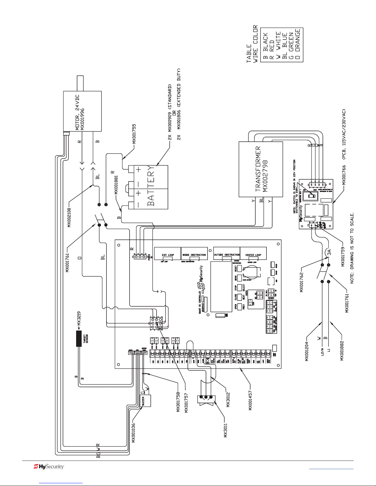
strongarmpark dC
IrIng sCHematICs
W
StrongArmPark DC 10 and StrongArmPark DC 14 Schematics
68 MX3650-01 Rev. D StrongArmPark DC Programming & Operations © 2017 www.hysecurity.com
Page 79
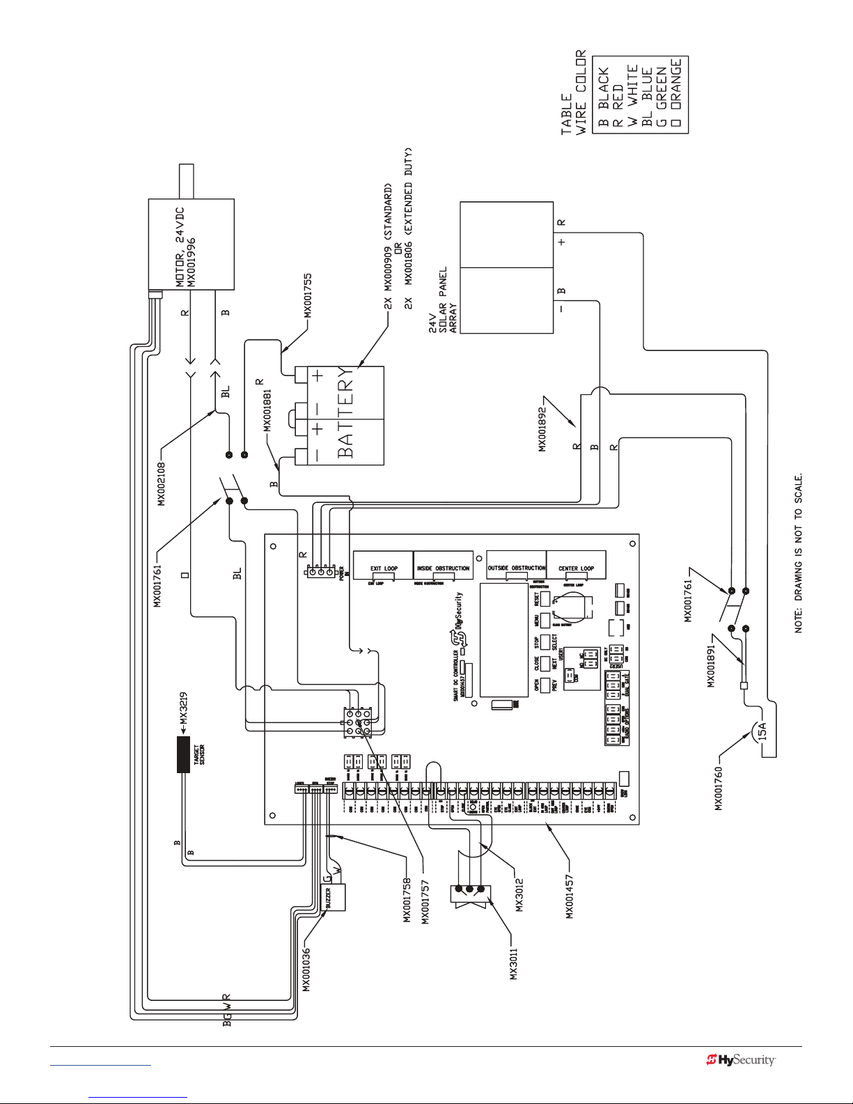
strongarmpark dC
WIrIng sCHematICs - solar
StrongArmPark DCS 10 Solar and StrongArmPark DCS 14 Solar Schematics
www.hysecurity.com © 2017 Troubleshooting MX3650-01 Rev. D 69
Page 80

Page intentionally left blank
70 MX3650-01 Rev. D StrongArmPark DC Programming & Operations © 2017 www.hysecurity.com
Page 81

General Maintenance
CAUTION
smart touCH analYze and retrIeve tool (s.t.a.r.t.)
HySecurity provides Smart Touch Analyze and Retrieve Tool
(S.T.A.R.T.) software to help HySecurity gate operator users and
installers conduct the following eld service activities:
• Congure installer and user menu settings
• View the operator history (event) log
• Display monitored inputs for operator diagnostics
• Load Smart Touch Controller or Smart DC (SDC) software
With S.T.A.R.T. software loaded on your laptop computer, you have an invaluable management tool for
all HySecurity operators. The USB port, allows you to download system diagnostics and upload system
congurations using the S.T.A.R.T. software. The free S.T.A.R.T. software is conveniently located at www.
hysecurity.com. Instructions for downloading S.T.A.R.T. are on the website.
What You Need
HySecurity Serial RS-232 communication cable with USB adapter
and current USB driver.
• Laptop computer with Windows PC operating system (XP,
RS-232
Vista, Win7, Win8, or Win 10)
USER RELAY 1
• Minimum 128MB of RAM
Electro-mechanical
• Minimum 5MB of hard drive disk space
C
• VGA graphics card (minimum resolution of 800 x 600)
D
R2
E
S
U
O
N
M
O
C
Installing S.T.A.R.T. Software
Read the S.T.A.R.T. User Manual, and then take the following steps to download S.T.A.R.T. software:
The latest version of S.T.A.R.T. is encrypted. An error message will appear stating that the le is corrupt if you try
to load new operator code using out-dated S.T.A.R.T. software. Be sure to “uninstall” any outdated versions of
S.T.A.R.T. from your laptop and install the latest version from www.hysecurity.com.
1. Bring up your web browser and type https://www.hysecurity.com in the command line.
2. Click Technical Support (left column) on the HySecurity home page.
USB
3. Click Download.
4. Enter your user name and password. If you do not have a user name, register as an online member.
5. Click S.T.A.R.T. Software for Smart Touch and SmartDC to being the software download.
www.hysecurity.com © 2017 General Maintenance MX3650-01 Rev. D 71
Page 82

6. Read the End User License Agreement and, if you agree to the terms, click, “I accept” (bottom of
CAUTION
COM
page).
7. Save the START< >_setup.exe le to your desktop.
8. Double-click the le to begin the installation.
9. Click RUN. A setup window appears.
softWare maIntenanCe
The software on the SDC board is periodically being enhanced with new features that create an easier install
and improve the on board diagnostic tools. Be sure to check the HySecurity website for the latest version of
software and operator code before heading out for eld maintenance.
eleCtrICal Controls
Before servicing, turn off all power switches.
No routine maintenance is needed for the electrical system or controls. If the environment is very sandy or
dusty, or has many insects, be certain to seal all holes in the electrical enclosure. Blow the dust out of the
electric panel with compressed air. Use the Table 8: Troubleshooting Codes on page 60 to assess and x
error, alert, and fault codes. If it is necessary to call a distributor for assistance, be sure to have your model and
serial number ready. Other helpful information includes the name of the job, approximate date of installation,
software version, and the service record of the operator, especially if any work has been done recently.
Clock Battery Replacement
A lithium coin battery supports the clock, so the date and time is retained even
when the main power is turned off. Replace the battery about every two years
(or as needed) with a DL 2025, DL 2032, or CR 2025, or CR 2032 battery.
Battery
Fuse Replacement
A 35A fuse is located next to the 24VDC power supply inputs on the SDC. It requires no maintenance, but if
it were blown due to a power surge or other unusual circumstance, it must be swapped out with a new fuse.
The symptoms of a blown fuse appear as a control system malfunction (i.e. all control systems may not work
properly).
72 MX3650-01 Rev. D StrongArmPark DC Programming & Operations © 2017 www.hysecurity.com
COM
Fuse
24VDC
24VDC
Page 83

meCHanICal maIntenanCe
CAUTION
Before checking the internal mechanisms of the operator, turn off all power switches.
The StrongArmPark DC mechanical maintenance is not in depth or difcult, but should be performed on a
routine basis. The operator chassis is zinc plated, but some environments may speed corrosion of this plating.
Schedule regular maintenance and look for the following:
• Assess that the drive belt has the proper tension. Check for drive belt wear. Fraying edges or missing
teeth indicate that the drive belt needs to be replaced.
• Check for signs of rust. If any areas of rust are found, reduce the spread of corrosion by treating the
areas with a rust inhibitor.
• Replace worn-out batteries.
• On the StrongArmPark DC 14 spring assembly, apply grease to zerk tting and upper rod end.
HyProtect™ Breakaway Arm Mount
The breakaway arm fasteners may need to be replaced from time to time. Use the following table to gauge
which fasteners should be used.
NOTE: Each bolt is secured with an aluminum lock washer and nylon hex nut. Torque to 15 in-lb.
Breakaway Fasteners
10 ft or shorter 2 nylon bolts Low wind
10 ft or shorter
10 ft or longer Low wind
10 ft or longer 2 steel bolts* High wind
NOTE: *Be aware, when using two steel bolts, that the arm may bend before the bolts break which voids the
Warranty.
1 nylon bolt
1 steel bolt
High wind
www.hysecurity.com © 2017 General Maintenance MX3650-01 Rev. D 73
Page 84

drIve Belt tensIon and alIgnment
Proper drive belt tension is important for prolonging the life of the drive belt and maintaining the superior
performance of the operator. To check the drive belt tension, take the following steps:
1. Remove the Front Access Panel.
2. Turn off the AC and DC power switches.
3. Remove the StrongArmPark DC top cover and drive belt cover.
4. Check to make sure the pulleys are aligned vertically.
5. With your nger, apply light outward pressure
to the drive belt. If it is properly tensioned, it
should only move about Z\zn to Z\,-inch (1.6 to
3.2 cm).
6. To replace or re-tension the drive belt. Loosen
the four motor bracket nuts and move the
motor accordingly.
7. Retighten the motor bracket nuts.
DC and AC
power switches
8. Replace the drive belt cover and top cover.
9. Turn the AC and DC power switches ON. This
cycles power which allows the operator to
Front access panel
search for the target magnet and “relearn”
its limits.
Top cover
Drive belt
cover
NOTE: Be aware that the arm will cycle open, and then
close, as it relearns its limits. If you don’t cycle the power,
the operator will not “relearn” its limits and will not operate properly.
Pulley
Z\zn to Z\,-inches
(1.6 to 3.2 mm)
Motor bracket nuts
LTR
74 MX3650-01 Rev. D StrongArmPark DC Programming & Operations © 2017 www.hysecurity.com
Page 85

dC BatterY replaCement
CAUTION
HySecurity provides a one year warranty from the date of shipment for all batteries supplied with the
StrongArmPark DC operator.
Display indicators of a low battery include:
• LOW BATTERY or DEAD BATTERY appears on the Smart DC Controller display which may or may not
be indicative of normal discharge.
• ALERT 18 CHANGE BATTERY appears on the
Smart DC Controller display. The operator emits
an audible chirp every minute to indicate a problem exists.
• AP (#) AC LOSS appears on the Smart DC Controller display. Gate operation is affected by AC power
loss depending on customer preferences and the conguration set by the installer in the AP (#) AC
LOSS User Menu.
Symptoms of a low battery may include:
• Gate remains locked in the open position
• Gate remains locked in the closed position
• Gate opens ve seconds after AC power loss and locks open
Before replacing the batteries, turn off all power switches. Use only AGM batteries as replacements (8Ah MX002008). The batteries supplied in the StrongArmPark DC operator are state-of-the-art AGM batteries. Do
NOT use ooded cell batteries as damage may occur to the unit. Wear protective clothing while working with
batteries.
www.hysecurity.com © 2017 General Maintenance MX3650-01 Rev. D 75
Page 86

The two 8Ah batteries are accessible within the operator on a tray next to the gear box.
To replace the batteries, take the following steps:
1. Remove the front access panel.
2. Turn off the DC and AC power switches.
3. Remove the top cover.
4. Access the two 8Ah batteries from the top.
Cut the two black wire ties holding the
batteries to the shelf.
5. Disconnect the red, blue, and black wires
as you lift the batteries through the access
window.
6. To install the two new batteries, reverse
the removal procedure.
• Install the rst battery and connect the
black wire.
• Connect the blue jumper wires
between the two batteries.
• Connect the red wire to the red
terminal on the second battery.
7. Replace the top cover.
Top cover
Cut-away View
Black
wire
Red
wire
Two 8Ah
batteries
8. Turn the AC and DC power switches
ON. This cycles power which allows the
operator to search for the target magnet
and “relearn” its limits.
NOTE: Be aware that the arm will cycle open and
close (close or open) as it relearns its limits. If you
don’t cycle the power, the operator will not
“relearn” its limits and will not operate properly.
9. Replace the front access panel and lock it.
Front access
panel
76 MX3650-01 Rev. D StrongArmPark DC Programming & Operations © 2017 www.hysecurity.com
Page 87
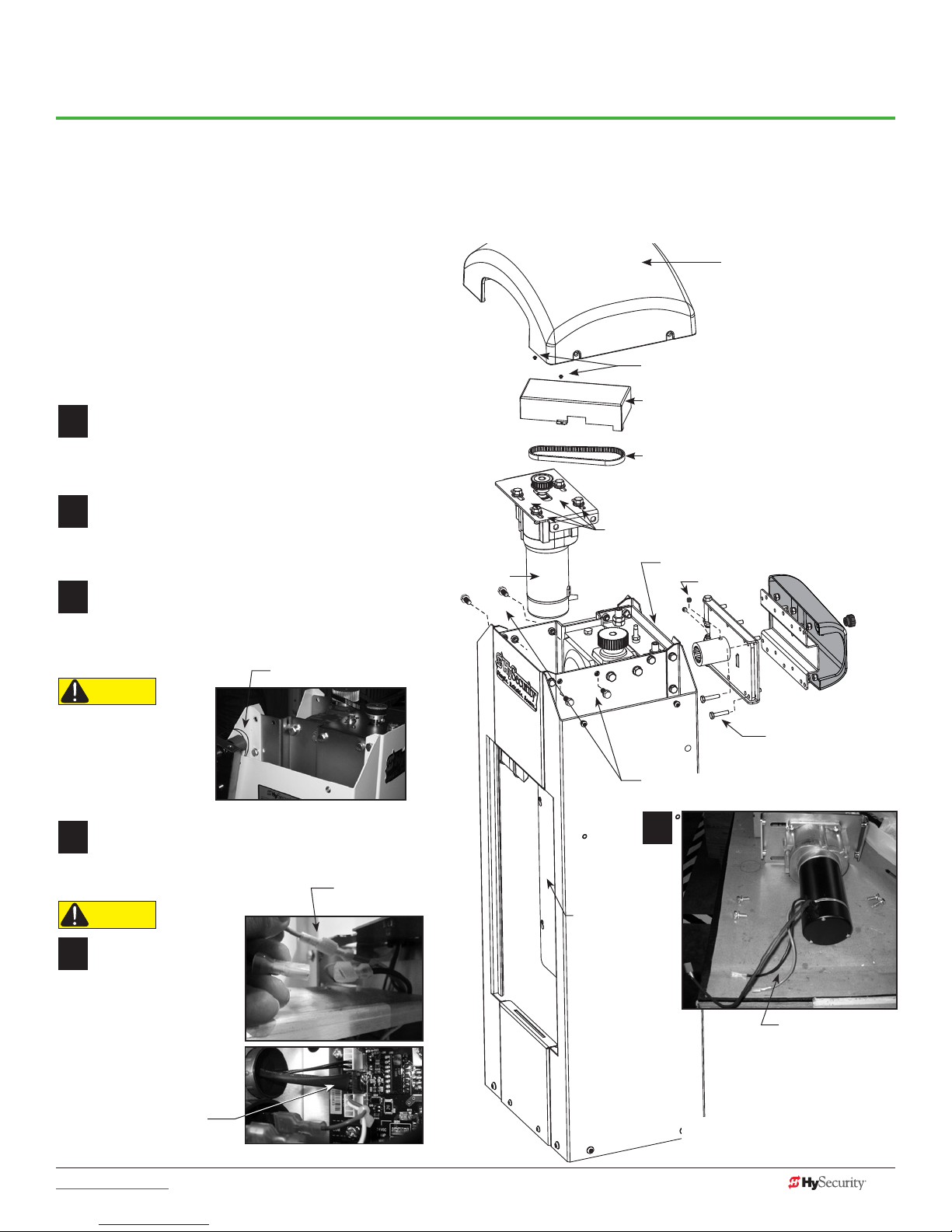
12
3
12
4
12
2
12
5
12
1
12
6
Reference
HandIng CHange
All StrongArmPark DC operators are shipped from the factory in a left handing conguration unless specied
otherwise. If you need to change the StrongArmPark DC14 handing at the site, you will need to:
• Release spring tension
• Swap locations of the spring’s eyebolt
and spacer on the physical stop lever
• Retention the spring
NOTE: If changing the handing on StrongArmPark DC10,
follow steps 1 and 10.
Remove the front access panel. (Keys come with
the operator.)
Use a phillips head screwdriver to remove the
plastic cover from the control box.
If the drive belt cover is in place, use a phillips
head screwdriver to remove two screws that
secure it to the motor plate. Set the drive belt
cover and fasteners aside.
Using a ½-inch socket wrench, remove four
fasteners securing the physical stop bracket.
(Do NOT break the wire connections.) Hang the
bracket from the side of the chassis, as shown.
Physical stop bracket
CAUTION
Wires are attached
to the physical stop
bracket. Do NOT sever
the wires or hang the
bracket by the wires.
Motor.
See
CAUTION
Top cover
Two phillips head screws
Drive belt cover
Drive belt
Loosen, DO NOT remove, 4 bolts
on motor cover plate
Physical stop bracket
Set screws
Nylon bolts for
breakaway bracket
Remove 4 bolts and lift the motor plate
assembly from the chassis. Set it aside.
Remove the drive belt. Use a >\zn-inch socket
wrench to loosen (do NOT remove) the 4 bolts
securing the motor to the motor plate.
CAUTION
Wires are attached
to the motor!
• Disconnect the 2 motor
wire leads from the
wire harness inside the
chassis.
• Disconnect the blue
connector wire from the
Smart DC Controller
and pull it out of the
control box.
www.hysecurity.com © 2017 Reference MX3650-01 Rev. D 77
Disconnect the
2 motor wires.
Control box:
Smart DC
Controller
access
Disconnect wire
leads before
removing the motor
ContInued....
Turn the page for more information.
Page 88

sprIng & pHYsICal stop lever assemBlY
12
7
12
8
12
9
12
10
Remove spring tension. Use a crescent wrench (or 12
point ratchet) to remove the square base nut and washer.
NOTE: You do not need to loosen the nut on the top of
the bracket. It helps keep the spring tension at factory
settings.
All thread rod
Square top nut
Square base nut
Swap physical stop lever hardware. Use a ¾-inch deep well
socket and box end wrench to remove the fasteners securing
the eyebolt. Then, loosen and remove the fasteners from
the other the physical stop lever and swap positions on the
physical stop levers.
Eyebolt
NOTE: For better access, you
can rotate the gear box to
reposition the physical stop
levers.
Reverse the steps found
on page 1.
• Insert the all thread and
re-attach the base nut.
• Tighten the two base nuts to
the required “H” dimension. See chart.
H
StrongArmPark DC 14
Arm Length
11 - 12 ft (3.6 m)
12 - 13 ft (4 m) 3 inches (76 mm)
13 - 14 ft (4.3 m)
NOTE: If the arm length is less than 11 ft (3.3 m), disconnect
the spring from the physical stop lever.
• Replace the motor and reconnect the 3 wire
leads.
• Replace the drive belt and adjust the tension
by sliding the motor plate and tightening
its 4 bolts.
• Replace the physical stop bracket
removed in step 3.
• Replace the drive belt cover.
Spring Setting (H)
3.5 inches (89 mm)
2.5 inches (63 mm)
Z\zn to Z\,-inch
(1.6 to 3.2 mm)
Physical stop
levers.
R
L
Swap
locations
(Remove/
Replace
fasteners
and
eyebolt.)
Spring
Square base nut
Set Handing
Turn ON the DC power switch and set the handing
using the Smart DC Controller.
• Press MENU twice.
• Press and hold OPEN and RESET, and then release.
• Press NEXT until GATE HANDING appears.
• Press SELECT. SH blinks.
• Press NEXT to set the handing (Left or Right).
• To accept what is being displayed, press SELECT.
• To exit Menu mode, press RESET.
• Turn OFF the DC power switch.
• Install the breakaway bracket by aligning its splines
with the gear box.
• Assemble the arm, apply power, and re-learn limits.
• Finish the site
installation.
SH R (RIGHT)
GATE HANDING
OPEN
PREV
CLOSE
NEXT
SELECT
STOP
MENU
RESET
78 MX3650-01 Rev. D StrongArmPark DC Programming & Operations © 2017 www.hysecurity.com
Page 89

InstallatIon InstruCtIons
Breakaway bracket and
Mounting bracket assembly
Quick Start Steps, MX3651-01.
described in StrongArmPark DC
mx4010
Tools required
• Box end wrenches: 7/16 and 9/16 inch
• Socket head wrenches: 7/16 and 9/16 inch
• 1/4 - inch Hex key
If the tip of the arm droops or angles up too much,
level the arm by tightening or loosen the linkage
fasteners that secure the rod ends.
Rod end is threaded. Loosen nut
and turn rod level arm.
Threaded rod
Channel in arm
Rod end is threaded.
for light string
Loosen nut and turn rod
level arm.
NOTE: Feed light cable
through Pivot Block.
To review an installation video for the standard StrongArmPark DC arm
lighting, click on the following link: http://bit.ly/breakawayinstall
Youtube video location: https://youtu.be/AdTWNYcC-NU
6.
Arm light cables inside
arm’s articulating bracket
Channel in arm
for light string
Tip of the arm
1/4 inch
fasteners
Connect arm light cables. Tuck
wiring inside arm channel.
Assembly of Lighted Articulating Arm
StrongArmPark DC Articulating Arm
Review the illustrations to understand the steps involved in assembling
the articulating arm and attaching it to the StrongArmPark DC chassis.
NOTE: If you are assembling the MX4010 kit on a non-articulating StrongArmPark DC,
refer to “StrongArmPark DC Breakaway Arm Bracket Installation” on page
www.hysecurity.com © 2017 Reference MX3650-01 Rev. D 79
Arm cap
Arm light
connectors
Pivot block
inside
articulating
bracket
Page 90
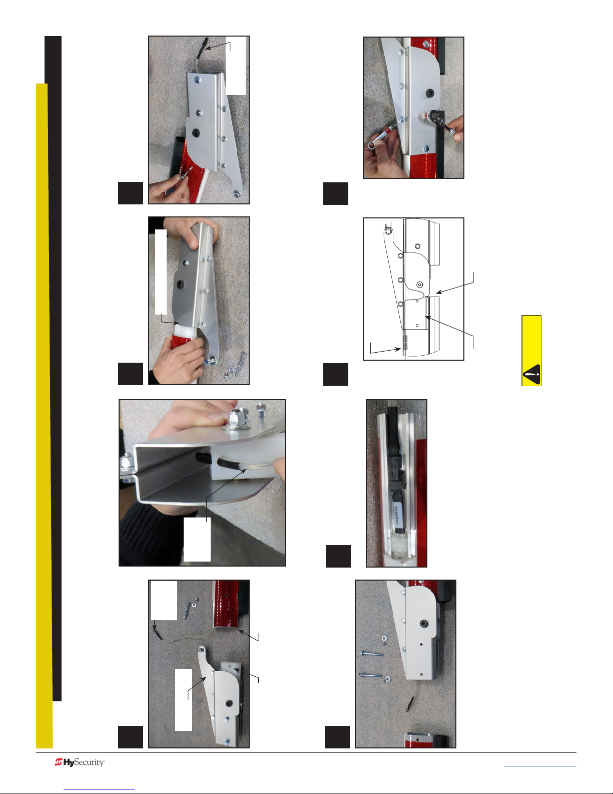
12
2
12
3
Secure Pivot Block with supplied
12
4
12
5
12
6
12
7
12
1
fasteners. Use box-end and socket
wrenches. Tighten bolt securely.
Light cable
and connector
Secure the arm to the Articulating Pivot
Bracket using the fasteners provided.
Tighten securely with socket and box-
end wrenches.
Arm light cables
inside arm’s
articulating bracket.
See CAUTION.
Pivot Block Assembly
Insert Pivot Block Assembly into
aluminum arm. Guide light cable
through Pivot Block hole.
Light
cable and
connector
Arm light
connectors
Insert Pivot Block Assembly into
aluminum arm. Guide light cable
through Pivot Block hole. Create a cable
loop. See CAUTION.
through the Pivot Block
Connect the arm lights. Place the
connectors inside the arm channel and
slide the arm into the Articulating Pivot
Bracket.
Feeding the cable (LED lighting)
Pivot block
inside
articulating
bracket
CAUTION
To allow full arm travel and minimal stress on the light connectors, check the cable loop
INSIDE the Articulating Pivot Bracket to be sure it moves freely and is not being pinched.
Light
cable and
connector
Feed cable through Pivot Block
and the Articulating Arm Bracket.
Articulating Arm
Bracket
Assemble the Pivot Block and Connect Light Strings
80 MX3650-01 Rev. D StrongArmPark DC Programming & Operations © 2017 www.hysecurity.com
Aluminum Arm
Pivot Block
Place the aluminum arms next to each
other as shown in the photograph.
Page 91

NOTE: When installing the breakaway bracket
it must be turned 90 degrees. See inset.
Feed wiring through
mid hole in chassis,
attach strain relief.
Then, mount
articulating bracket to
chassis.
Secure cable
with strain relief
bushing.
Arm lights
connection
Proper orientation of
Assemble Arm onto chassis
breakaway bracket
during installation
Fasten Articulating Arm Bracket to Rod End and attach assembly to Chassis
Feed Cable through Chassis
StrongArmPark DC: Articulating Arm Assembly
Follow the exploded views and secure the fasteners as shown.
Remove smaller
plugs to mount
articulating arm
strut.
www.hysecurity.com © 2017 Reference MX3650-01 Rev. D 81
Remove Plugs in Chassis
Remove center plug
to feed wire harness
cable through
chassis.
Cable loop length:
8-inches (20 cm)
CAUTION
To allow full arm travel, the cable loop
on the outside of the chassis must be a
minimum 8-inches (20 cm) in length.
Page 92
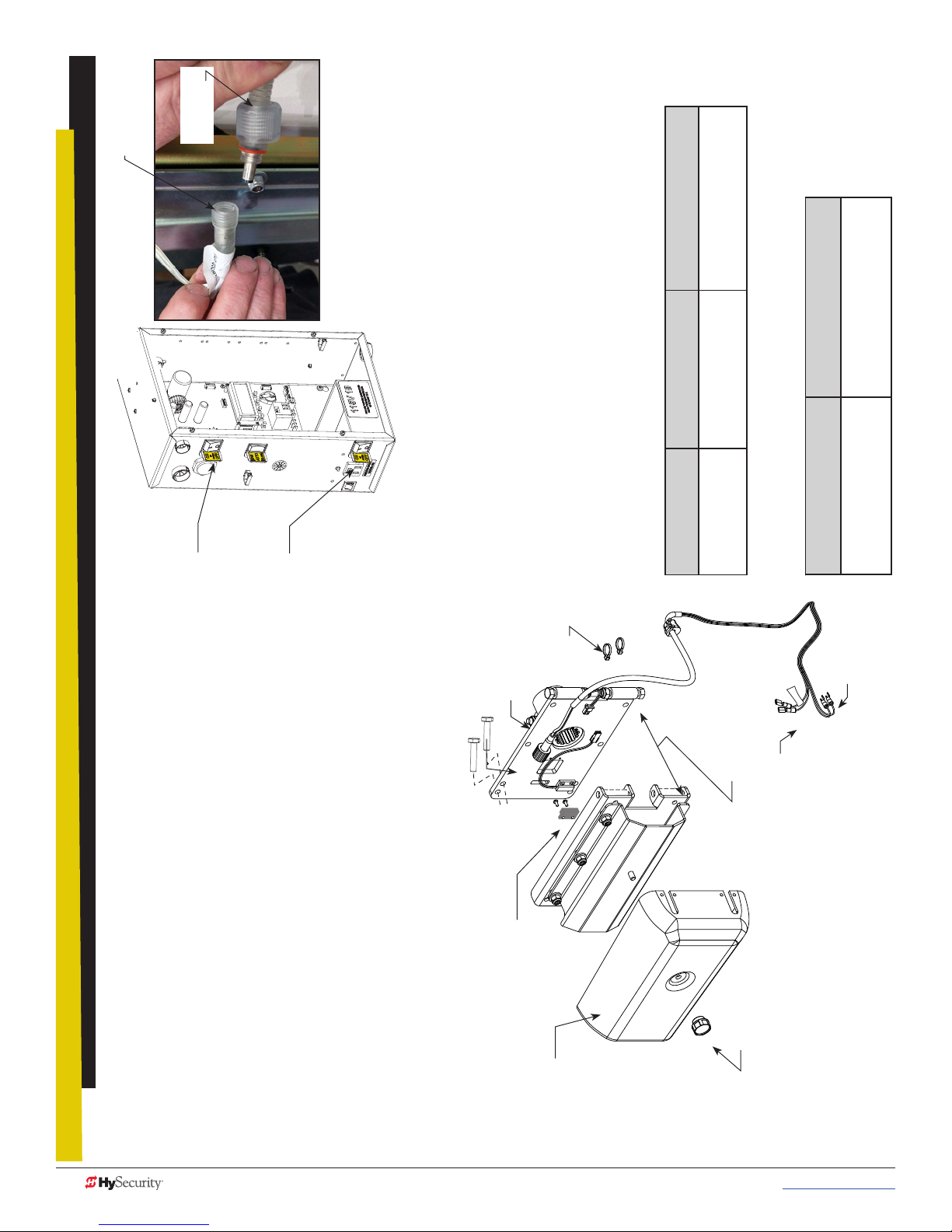
LED Arm light
connector
Wire harness
connector
DC Power
Switch
AC Power
Switch
Connect Arm Light Cables
power supply terminal. See wiring illustrations.
Turn OFF AC and DC power
5. Connect female quick connect labeled +24V to the 24VDC
6. Connect the second female quick connect to the NO terminal on
NOTE: If you are planning to program the proximity sensor in the breakaway
bracket assembly, connect one spade connection to COM and the other to
User Relay 2.
SENSOR 3 (Photo Eye Close on BY1 operators).
selections.
To navigate through
Press Next or Previous.
the menu item selections
Continue pressing Next to view all
Press Select.
To change menu item
To access
Smart DC Controller: Menu Mode Navigation Buttons
Two left characters blink.
appearing in the display
twice.
Menu mode
Press the Menu button
menu items
To navigate between
To choose what item appears
Advance - press Next
Press Next or Previous.
Previous - press Previous
Press Select.
on the display
become static.
Blinking characters
the two bracket mounts. Feed the cable through the interior of
the chassis. Pull enough cable to reach the Smart DC Controller
terminals.
NOTE: Connect wire lead (female quick connect) labeled +24V to 24VDC.
Lights will be dim if lead is connected to 12VDC terminal.
1. Make sure both AC and DC power switches are turned OFF.
2. Insert leads of wire harness through the hole in chassis between
chassis) to the LED light connector on the arm. The wire harness
connector is keyed. Be sure to seat the connectors before
3. Attach the end of the wire harness (on the outside of the
Wire ties
bolt & nut
End cap
threading close. See illustration on previous page.
relief bushing. See illustration on previous page.
Spline collar
Breakaway
fasteners
Factory installed magnet
(kill switch)
4. Make sure the harness is secured to the chassis with the strain
+24V
Shown separated
for reference only
Connections to Controller
Female Quick Connects:
User2 Relay (NO) & +24VDC
Knob
Spade
connections
Spade connections:
COM & SENSOR 3
Exploded View
StrongArmPark DC: Lighting Connection
82 MX3650-01 Rev. D StrongArmPark DC Programming & Operations © 2017 www.hysecurity.com
Page 93

PREV
SENSOR 2
SENSOR 3
SENSOR 1
+24V
12VDC
24VDC
COM
proximity switch in the
breakaway arm assembly,
navigate to BA in the
5. To turn on the magnetic
12VDC
24VDC
COM
COM
Installer Menu.
COM
COM
COM
COM
COM
STOP
menu item to 1.
6. Select BA and change the
7. Exit the Installer menu mode
OPEN
RADIO
OPEN
OPEN
PARTIAL
EYE
OPEN
EYE
CLOSE
CLOSE
by pressing Menu and return
to run mode.
C
D
S
E
R2
Electro-mechanical
USER RELAY 1
EXIT
LOOP
BLOCK
EXIT
IN OBS
LOOP
OUT OBS
LOOP
CENTER
LOOP
EDGE
EYE
COM
+ 24 V
EMERG
NOTE: For the menu
mode navigational
buttons, refer to the
chart on page 4.
O
N
M
O
C
U
USER RELAY 2
Solid state
1
S
24V
+
EN
OP
M
O
C
A
E
T
A
G
B
AL
M
U
O
D
C
SHOW
LEDs
OPEN
Arm Lights and Breakaway Switch
Connections on Smart DC Controller
Remove center plug to feed wire
harness cable through chassis. If
plug doesn’t exist, a 5/8-inch access
hole may need to be drilled.
• Standard drill set
Retrofit Requires Hole Drilled in Chassis
• Electric drill
Tools Required
To retrot a StrongArmPark DC with MX4122 cable
lighting, you will need to drill a 5/8-inch hole in the
chassis. The hole provides
a means to feed the light
cable through the chassis and
attach wires for power and
programming purposes to the
controller.
Press SELECT. The
“R2” characters blink.
Installer Menu
R2 28 FLASH AC
Installer Menu
R2 0 DISABLED
...until “R2 0 DISABLED” appears.
continue to press Next,
Press Next until ““R2 28 FLASH AC” appears (Or
choose R2 “27” if you don’t want the lights to ash.)
Press SELECT again to set the User Relay 2 function.
Press Next, and...
RESET
User Menu
Status Display
GATE CLOSED
turn off when open limit is reached.
search for the target home position.
1. Turn on both AC and DC power switches. Arm will cycle to
2. When the arm has stopped moving, access the Installer Menu.
• R2 “27”: LED lights remain on throughout arm travel and
3. Set the User Relay 2 logic function to one of the following:
when open limit is reached.
• R2 “28”: LED lights ash throughout arm travel and turn off
NOTE: In the event of AC power loss, either selection (27 or 28) turns off
the lights which preserves battery life.
4. Set the breakaway switch or press Menu to return to run mode.
Press MENU
twice at a Run
Mode static
RELAY 2: INSTALLER MENU FLOW DIAGRAM
display.
CT 0 (OFF)
To access the Installer
Menu, press and hold
RESET & OPEN, and then
release them.
R2 28 FLASH AC
RELAY 2 LOGIC
MENU
STOP
CLOSE
OPEN
www.hysecurity.com © 2017 Reference MX3650-01 Rev. D 83
SELECT
NEXT
Page 94

Top cover
12
2
12
3
12
1
12
4
12
5
12
6
12
8
12
7
HYSECURITY
Physical Stop
Bracket
Physical Stop
Bracket fasteners (4x)
GATE OPEN
RESET
MENU
STOP
CLOSE
OPEN
SELECT
NEXT
PREV
After GATE OPEN appears on the
display, turn the DC power switch OFF.
DC power switch
Connect the red battery wire.
(Refer to step 4 in the Installation
Make sure AC and DC power switches
are in the OFF position.
Instructions.)
Press the DC switch ON and toggle
HOLD switch to Hold Open.
Display
HOLD
toggle
switch
AC power
switch
Front access
panel
Spline collar
bolt & nut
Position Breakaway Arm
Slide the clamp onto the drive
shaft. Align gear teeth as you
slide clamp against chassis.
NOTE: You may need to loosen the collar bolt & nut to
Bracket so the clamp
opening faces up.
NOTE: Follow the video to feed wire harness through chassis, assemble
barrier arm, connect lighting and program the gate operator.
Secure clamp to drive shaft
using the fasteners provided.
position the clamp. Re-tighten when spline properly set .
Standard socket set
• Utility knife
raCket InstallatIon
strongarmpark dC BreakaWaY arm
84 MX3650-01 Rev. D StrongArmPark DC Programming & Operations © 2017 www.hysecurity.com
B
Tools Required
•
Remove Physical Stop
Bracket (4 fasteners)
• Standard hex key set
1. Install the breakaway arm bracket
2. Connect the magnetic kill switch
3. Connect the arm lighting and feed wire through the chassis to the controller (5:50 min)
To review the installation video, scan the QR code with your cell phone or
click on the following link: http://bit.ly/breakawayinstall
Youtube video location: https://youtu.be/AdTWNYcC-NU
In a short 8 minutes, the installation video shows you how to:
4. Program the controller, Installer Menu setting “BA” Breakaway switch.
To install the breakaway arm bracket onto the StrongArmPark DC, you can take
the steps shown here and view the video for additional step clarication.
Page 95

WarrantY
1. Warranty.
Hy-Security Gate, Inc. (“HySecurity”) warrants that at the time of sale each of its
products will, in all material respects, conform to its then applicable specication and
will be free from defects in material and manu-facture.
The following additional durational warranties apply to HySecurity products,
depending on whether (1) the product is purchased through an authorized
HySecurity distributor and (2) whether a timely and complete product registration is
submitted to HySecurity.
It is therefore important that you register your product with HySecurity, online at
www.hysecurity.com/warranty, within the 60-day period described below.
1(a) HySecurity Products Purchased Through Authorized Distributors and
Properly Registered
For any gate operator product that is purchased from an authorized HySecurity
distributor (this excludes product purchased through internet resellers or any
distributor not authorized by HySecurity), if the product registration is completed
by the Dealer/Installer/End User within 60 days of the date of purchase, the
following warranty terms will apply. HySecurity warrants that the product will
remain serviceable for the following periods:
a. Hydraulic industrial gate operators hydraulics, controls, and mechanical
components: Five Years or 500,000 gate cycles (whichever occurs rst) after
the date of installation,
b. Hydraulic wedge operator hydraulics and controls: Five Years or 500,000
cycles (whichever occurs rst) after the date of installation. Wedge
mechanical components: Two Years after the date of installation,
c. Electromechanical Slide and Swing operators: Five Years or 500,000 cycles
(whichever occurs rst) after the date of installation, except single family
residential usage, where the warranty term shall be Seven Years after the date
the product was shipped from HySecurity,
d. Electromechanical surface mount wedge operator electronics: Two Years or
500,000 gate cycles (whichever occurs rst), after the date of installation,
e. Electromechanical Barrier Arm Operators: Two years or 1,000,000 gate cycles
(whichever occurs rst) after the date of installation,
provided that the preceding Five Year warranty period in (a), (b) and (c) will not
extend beyond seven years from the date that the product was shipped from
HySecurity, and the Two Year warranty period in (b), (d) and (e) will not extend
beyond four years from the date that the product was shipped from HySecurity.
The preceding warranty durations do not apply to the products or components
described below (f-i), which have a shorter warranty period.
f. Hydraulic gate operator drive wheels including XtremeDrive™ wheels and
rack: Two Years from date of installation.
g. AC and DC power supplies, chargers and inverters and HyNet™ Gateway:
Two Years from date of installation, except batteries.
h. Batteries: One Year from date of shipment from HySecurity.
i. Components subject to normal wear including, but not limited to, chains,
belts, idler wheels, sprockets and fuses: One Year from date of installation.
1(b) HySecurity Products Not Purchased Through an Authorized Distributor or
Not Properly Registered within 60 Days
For any product that is not purchased from an authorized HySecurity distributor
or for which the product registration was not completed by the Dealer/Installer/
End User within 60 days of the date of purchase, the following One-Year Limited
Warranty will apply: HySecurity warrants that the product will remain serviceable
for the following periods, which begin on the date that the product was shipped
from HySecurity:
a. All gate operators: One Year or 100,000 gate cycles whichever comes rst.
b. AC and DC power supplies, chargers or inverters: One Year.
c. HyNet™ Gateway: One Year.
d. Hydraulic gate operator drive wheels: One Year.
1(c) Replacement Parts
HySecurity warrants that replacement parts (whether new or reconditioned) will
remain serviceable for One Year from the date that the product was shipped
from HySecurity or the remaining period of the Gate Operator warranty,
whichever is longer.
1(d) Limitations and Exclusions Applicable to Each of the Preceding Warranties.
The preceding warranties shall not apply to equipment that has been
(1) installed, maintained, or used improperly or contrary to instructions;
Warranty D0317 Revised 031517
(2) subjected to negligence, accident, vandalism, or damaged by severe
weather, wind, ood, re, terrorism or war; or (3) damaged through improper
operation, maintenance, storage or abnormal or extraordinary use or abuse. Any
modication made to products will void the warranty unless the modications are
approved in writing by HySecurity in advance of the change (this exclusion does
not apply to normal installation of approved accessories and/or protective devices
or sensors). It is the responsibility of the distributor, installer, or End User to ensure
that the software version in the product is maintained to the latest revision level.
The preceding warranties do not extend to accessories when those items carry
another manufacturer’s name plate and they are not a part of the base model.
HySecurity disclaims all warranties for such accessory components, which carry
only the original warranty, if any, of their original manufacturer. HySecurity hereby
assigns its rights under such manufacturer warranties—to the extent that such
rights are assignable—to Buyer.
These warranties extend to HySecurity’s Distributors, to the Dealer/Installer, and
to the rst End User of the product following installation. They do not extend to
subsequent purchasers.
2. Exclusion of Other Warranties.
The warranties contained in Section 1 are the exclusive warranties given by
HySecurity and supersede any prior, contrary or additional representations, whether
oral or written. Any prior or extrinsic representations or agreements are discharged
or nullied. HYSECURITY HEREBY DISCLAIMS AND EXCLUDES ALL OTHER
WARRANTIES—WHETHER EXPRESS, IMPLIED, OR STATUTORY—INCLUDING ANY
WARRANTY OF MERCHANTABILITY, ANY WARRANTY OF FITNESS FOR A
PARTICULAR PURPOSE, ANY LIABILITY, FOR INFRINGEMENT, AND ANY IMPLIED
WARRANTIES OTHER¬WISE ARISING FROM COURSE OF DEALING, COURSE OF
PERFORMANCE, OR USAGE OF TRADE.
3. Buyer’s Exclusive Remedies for Any Nonconformity.
If a HySecurity product fails to conform to the warranties in Section 1, Buyer must
notify and order replacement parts from the Distributor through which the product
was purchased within a reasonable time and in no event more than thirty (30) days
after the discovery of the nonconformity. HySecurity will investigate and, in the event
of a breach, will provide, within a reasonable period of time, one of the following: (1)
repair or replacement of any nonconforming products or components or (2) refund
of the price upon return of the nonconforming items. HySecurity reserves the right to
supply used or reconditioned material for all warranty claims. HySecurity will not be
considered to be in breach of or default under this Warranty because of any failure to
perform due to conditions beyond its reasonable control, including any force majeure.
This warranty does not cover any incidental expenses, including nes or penalties,
temporary security, labor, shipping, travel time or standby time that are incurred for
inspection or replacement of any nonconforming items. As a condition of warranty
coverage, warranty claims must be submitted in accordance with the procedures
described on the HySecurity form, “RMA Procedures.”
THE REMEDY SELECTED BY HYSECURITY IN ACCORDANCE WITH THIS
PARAGRAPH SHALL BE THE EXCLUSIVE AND SOLE REMEDY OF BUYER FOR
ANY BREACH OF WARRANTY.
4. Exclusion of Consequential and Incidental Damages.
HYSECURITY SHALL NOT BE LIABLE FOR ANY INCIDENTAL, SPECIAL, OR
CONSEQUENTIAL DAMAGES, WHETHER RESULTING FROM NONDELIVERY
OR FROM THE USE, MISUSE, OR INABILITY TO USE THE PRODUCT OR FROM
DEFECTS IN THE PRODUCT OR FROM HYSECURITY’S OWN NEGLIGENCE. This
exclusion applies regardless of whether such damages are sought for breach of
warranty, breach of contract, negligence, or strict liability. This exclusion does not
apply to claims for bodily injury or death.
5. Severability.
If any provision of this warranty is found to be invalid or unenforceable, then the
remainder shall have full force and effect.
6. Proprietary Rights.
HySecurity retains and reserves all right, title, and interest in the intellectual
property rights of its products, including any accompanying proprietary software.
No ownership of any intellectual property rights in the products or accompanying
software is transferred to Distributor, Dealer/Installer or End User.
7. Applicable Law.
This warranty will be interpreted, construed, and enforced in all respects in
accordance with the laws of the State of Washington, without reference to its choice
of law principles. The U.N. Convention on Contracts for the International Sale of
Goods will not apply to this warranty.
www.hysecurity.com © 2017 MX3636-01 Rev. C 85
Page 96

speCIfICatIons
Standard WedgeSmart DC 10 WedgeSmart DC 14 Solar
Arm Length Capacity 10 ft (3 m) 14 ft (4.3 m)
Field Adjustable
Open/Close Time
Full Open Angle Adjustable 90°± 10° Adjustable 90°± 10°
Handing
Maximum Gate/Arm Load
Power: Single Phase
(switch selectable)
Duty Cycle Continuous Continuous Continuous
Accessory Power 1A each at 12VDC, 24VDC & 24VAC 1A each at 12VDC, 24VDC & 24VAC 1A each: 12VDC & 24VDC
DC Batteries Two 12VDC, 8Ah batteries. Field congurable to fail open or secure (close) when batteries deplete.
Programmable Output Relays
User Controls Smart DC Controller (32 character LCD display, 5 tact buttons). S.T.A.R.T. software with PC laptop.
Communication USB, RS-232, RS-485
Three speeds: 1.5, 2, and 2.5
seconds
Left handing standard. Easy to
convert to right handing in eld.
8 lbs/3.6 kg at 10 ft/3 m
(0.8 lbs per foot, 0.4 kg per 30 cm)
115 Volts, 3 amps, 50/60 Hz
230 Volts, 1.5 amps, 50/60 Hz
Two congurable user relays: 30VDC, 3A Solid State and 250VAC, 10A electromechanical.
Optional: Extended Relay Module (8 ports)
Three speeds: 2.5, 3, and 3.5
seconds
Left handing standard.
Right handing optional.
11.2 lbs/5 kg at 15 ft/4.3 m
(0.8 lbs per foot, 0.4 kg per 30 cm)
115 Volts, 3 amps, 50/60 Hz
230 Volts, 1.5 amps, 50/60 Hz
24VDC
Temperature Rating -13°F to 158°F (-25°C to 70°C) No heater necessary.
UL 325 Compliant Usage Class I,II, III, IV
Limited Warranty Operator: 2 years
Copyright Notice
© Copyright 2017 by HySecurity Gate, Inc.
All rights reserved. No part of this manual may be reproduced by any means (photocopier, electronic, or mechanical), without the express written permission of HySecurity Gate,
Inc. Federal copyright law prohibits the reproduction, distribution, or public display of copyrighted materials without the express written permission of the copyright owner, unless
fair use or other exemption under copyright law applies. Additionally, HySecurity Gate, Inc. makes no representations or warranty with respect to this manual. We also reserve the
right to make changes in the products described without notice and without any obligation to notify any persons of any such revision or change.
Trademarks
SlideDriver, StrongArm, SwingRiser, StrongArm CRASH, StongArm M30, StrongArm M50, HydraLift, HydraSwing, HydraWedge SM50, HydraSupply XL, HydraSupply, HyNet,
Hy8Relay, HyInverter AC, HyCharger DC, SlideWinder, Smart Touch, S.T.A.R.T., SwingSmart DC, SlideSmart DC, StrongArmPark DC, WedgeSmart DC, Smart DC and the
HySecurity logo are trademarks or registered trademarks of HySecurity Gate, Inc.
UL and UL logo are trademarks of UL LLC and ETL is a trademark of Intertek.
Intertek provides the ETL Listed Mark.
Products called out in Wiring HySecurity Sensors are trademarks or registered trademarks of Miller Edge, Inc., OMRON Corporation, and Encon Electronics.
86 MX3654-01 Rev. A StrongArmPark DC Programming & Operations © 2017 www.hysecurity.com
 Loading...