

HySecurity HYNET GATEWAY SFP 4/1, MX3867, StrongArmPack DC 10, StrongArmPack DCS 10, StrongArmPack DC 14 Installation Manual
...Page 1
StrongArmPark DC 10 and StrongArmPark DCS 10
StrongArmPark DC 14 and StrongArmPark DCS 14
Installation Manual for HyNet Attachment: MX3867
This document is a supplemental document that provides specic information regarding
conguration of the HySecurity gate operator with installation and wiring of the HyNet Gateway.
For safety considerations and information specic to your gate operator, refer to the HySecurity
gate operator product manuals.
Page 2
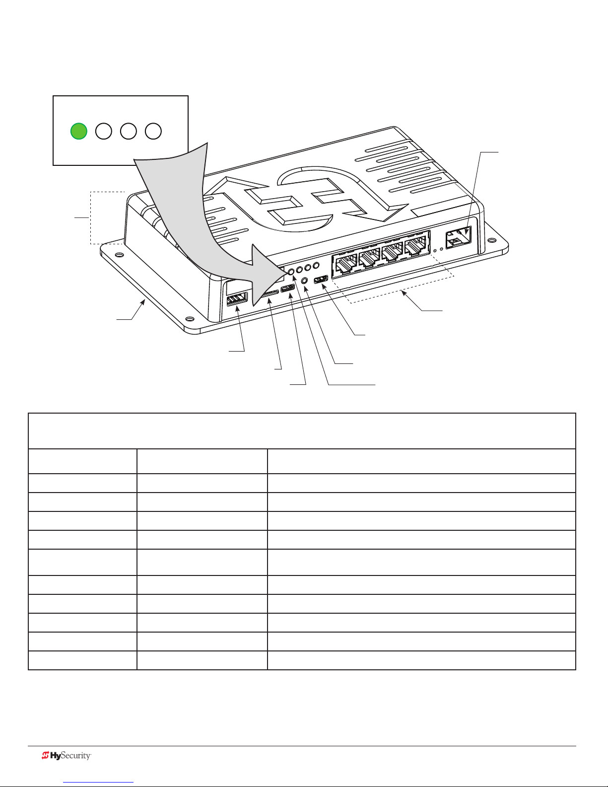
HyNet Components
LED Indicators
4321
Height
1¼ inches
SFP Module
(100/1000/2500)
Mounting Plate
4 x 7½ inches
RS-485
Micro SD Card Slot
USB OTG
Micro USB
Reset Button
LED (position 1)
Table 1: HyNet LED Indicators
LED Position LED Color Indicates
1 RED ashing No communication from gate operator to HyNet.
1 Green steady Communication is established between gate operator and HyNet.
2 RED steady Gate operator network communication is not congured or established.
2 RED ashing HyNet is attempting to connect to network (web interface).
2 GREEN ashing
3 RED steady Hardware fault.
Network (web interface) is established and working. (May not be wholly
congured, yet. Verify conguration with your IT administration.)
Managed Switch
RJ-45 Integration Hub
4-Port Copper Gigabit
(100/1000/2500)
3 RED ashing Charge is low on coin battery. Replace coin battery.
3 GREEN steady Hardware functioning and coin battery charged.
4 Red steady or no LED lit HyNet internal switch is not functioning.
4 GREEN steady HyNet internal switch is functioning.
Drawing is not to scale
2 D0719 Rev. C HyNet Aachment Kit: MX3867 © 2016 www.hysecurity.com
Page 3
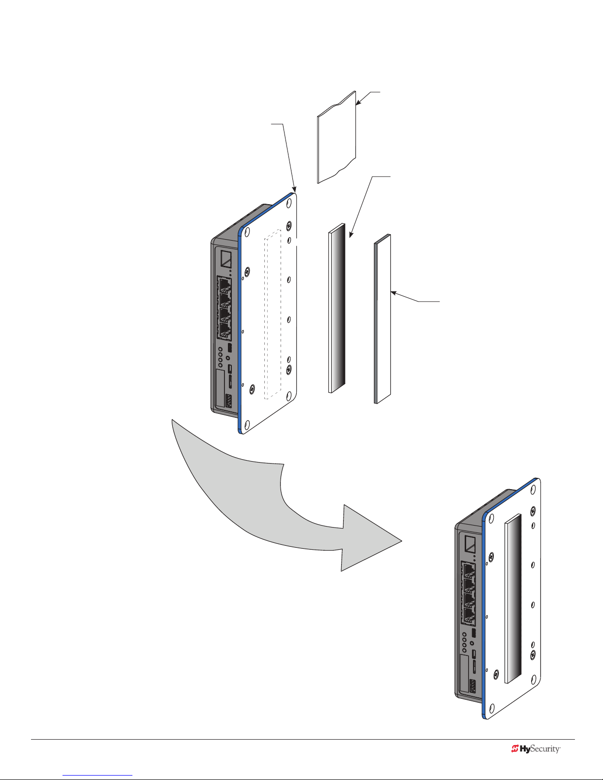
StrongArmPark DC HyNet Assembly
Alcohol wipe
Use alcohol wipe to clean
HyNet mounting plate
mounting plate surface before
applying Velcro
Velcro strip
Peel off protective layer and adhere
Velcro
®
®
strip to HyNet mounting plate.
Velcro
Adhere to gate operator
chassis.
adhesive backing.
®
strip
HyNet Assembly
www.hysecurity.com © 2016 StrongArmPark DC Installation D0719 Rev. C 3
Page 4

Mount HyNet to StrongArmPark DC and
StrongArmPark DCS
Set the HyNet onto the
chassis so the ports are
accessible as shown in the
illustration.
Connect wiring.
5
6
See page 5.
Replace and secure
covers.
4
Remove front
cover panel
4 D0719 Rev. C HyNet Aachment Kit: MX3867 © 2016 www.hysecurity.com
1
Peel protective paper off
®
Velcro
strip.
2
Adhere the Velcro® strip to the inside portion of
the StrongArmPark DC chassis. Press rmly.
3
NOTE: Recommended HyNet location is shown in
the illustration. Ambient temperature for adhesion
is between 45˚ and 85˚ F.
Page 5

Wiring the HyNet Gateway
24VDC
24VDC
24VAC
24VAC
12VDC
12VDC
HyNet
RS-485 port
Pin 1, +24V
RS-485
Connector
Attach to RS-485
port on HyNet.
1
5
Supply
RJ-45 network
connection
COMMON
TERMINALS
Optional +24VDC
if RADIO OPTIONS
+24V is occupied
COM
COM
COM
COM
COM
COM
COM
COM
STOP
OPEN
CLOSE
RADIO
OPEN
PARTIAL
SENSOR 2
SENSOR 3
EXIT
LOOP
BLOCK
EXIT
IN OBS
LOOP
OUT OBS
LOOP
CENTER
LOOP
SENSOR 1
SENSOR
COM
+ 24 V
EMERG
OPEN
Smart DC Controller
24VDC
24VDC
12VDC
12VDC
OPEN
M
O
SHOW
LEDs
C
DU
Installer supplied shielded
cable
Attach shielded
cable to wire
2
harness.*
*Measure distance
between HyNet and
Controller connections
for appropriate
shielded cable length.
NOTE: More detailed
wiring information is
shipped with the HyNet.
Wire harness
(supplied in box)
2
DC
ER
S
U
E
G
D
E
V
M
O
+24
C
N
E
P
O
COM
A
B
E
T
A
G
L
A
NS
O
I
T
P
O
O
ADI
R
USB port
RS-485 ports
O
N
Pin 1,
COM
Connect to RS-485
port on Smart DC
3
Controller.
Connect ying
lead to +24V.
Drawing is not to scale.
www.hysecurity.com © 2016 StrongArmPark DC Installation D0719 Rev. C 5
4
2
C
D
R
E
S
U
A
COM
2
+
E
G
D
E
O
O
I
D
A
R
DU
S
ON
I
T
P
TE
A
G
L
A
B
COM
N
E
P
O
V
4
COM
O
N
NOTE: The Smart DC Controller pin layout changed a
few years ago. On controllers with part numbers
marked MX001457 and MX3037 Revisions A, B, and C,
be sure you're connecting the ying lead to the +24V
spade located under RADIO OPTIONS.
Page 6

Smart DC Controller
HySecurity gate operators provide a 2-wire, serial interface (RS-485 connection) which allows remote access to
one or more operators.
When the physical connection is made and protocols are established, an SA (System Address) must be assigned
for each operator through its Installer Menu.
For network communication, choosing a “SA” of 1 to 4 establishes individual network polling addresses. HyNet
only utilizes numbers 1, 2, 3, or 4.
A “SA” of zero means no network communication is desired.
COMMON
TERMINALS
COM
COM
COM
COM
COM
COM
COM
COM
STOP
OPEN
CLOSE
RADIO
OPEN
PARTIAL
SENSOR 2
SENSOR 3
EXIT
LOOP
BLOCK
EXIT
IN OBS
LOOP
OUT OBS
LOOP
CENTER
LOOP
SENSOR 1
SENSOR
COM
+ 24 V
EMERG
OPEN
OPEN
SHOW
LEDs
24VDC
24VDC
12VDC
12VDC
To access Installer Menu, press
Menu button twice. Then, press
1
Reset and Open.
Press Select to navigate to
Installer Menu item "SA"
System Address.
SA 0 (OFF)
SYSTEM ADDRESS
SA 1
SYSTEM ADDRESS
CLOSE
OPEN
NEXT
PREV
STOP
SELECT
MENU
RESET
Press Select again to set gate
operator's system address
2
DC
ER
S
U
E
G
O
D
E
B
M
O
C
DU
E
T
A
G
L
A
P
O
O
ADI
R
V
+24
N
E
P
O
COM
A
N
M
O
C
NS
O
I
T
2
(Each gate operator attached
to the same HyNet must have
a unique SA number. Choose
1, 2, 3, or 4.)
To exit Menu mode, press Menu. The
3
gate operator returns to Run mode.
Refer to Table 1: HyNet LED Indicators on page 2.
4
Solid green means serial communication is active and
functioning well.
For IP network setup, refer to the HyNet Quick Start
5
6 D0719 Rev. C HyNet Aachment Kit: MX3867 © 2016 www.hysecurity.com
manual supplied in the HyNet box.
Page 7

Installer’s CheCklIst
Date Installed: ________________ Gate Operator Model: _________________________________________________________________
Site Location: __________________________________________________________________________________________________________
HyNet Serial Number: ___________________________________
Gate Operator Serial Number: ___________________________
Gate Operator Serial Number: ___________________________
Gate Operator Serial Number: ___________________________
Gate Operator Serial Number: ___________________________
Customer Name: _______________________________________________________________________________________________________
Mailing Address: ________________________________________ Inspected by: ____________________________________________
________________________________________________________ Date Inspected: __________________________________________
Phone Contact: _________________________________________ Phone contact number: ___________________________________
Checked Initials
1. Site Planning _____________
RJ-45 cable to system network.
2. Safety _____________
Review Important Safety Information in the gate operator's product manual.
Warning labels apparent and afxed properly.
Area around the gate and gate operator free of debris, cabinets/chassis include locking mechanism.
3. Electrical _____________
3.1 Grounding
• NFPA 780 Standard for the Installation of Lighting Protection Systems.
• Solid copper ground rod (⅜-inch diameter, 10 ft length) driven into ground within 3 ft of the gate operator.
• Single length of unspliced 6AWG copper wire less than 3 ft long attached to lug nut in gate operator.
3.2 Gate operator has current software loaded.
3.3 Congure the Controller
• Set the System Address (SA) in the Installer Menu.
• Communicate (verify) system address to IT Network Admin for proper web page conguration.
4. Review gate operator installation checklist from gate operator manual _____________
5. Take photographs of installation and provide an End User Demo _____________
www.hysecurity.com © 2016 StrongArmPark DC Installation D0719 Rev. C 7
Page 8

8 D0719 Rev. C HyNet Aachment Kit: MX3867 © 2016 www.hysecurity.com
 Loading...