

Page 1
QUick Start StepS
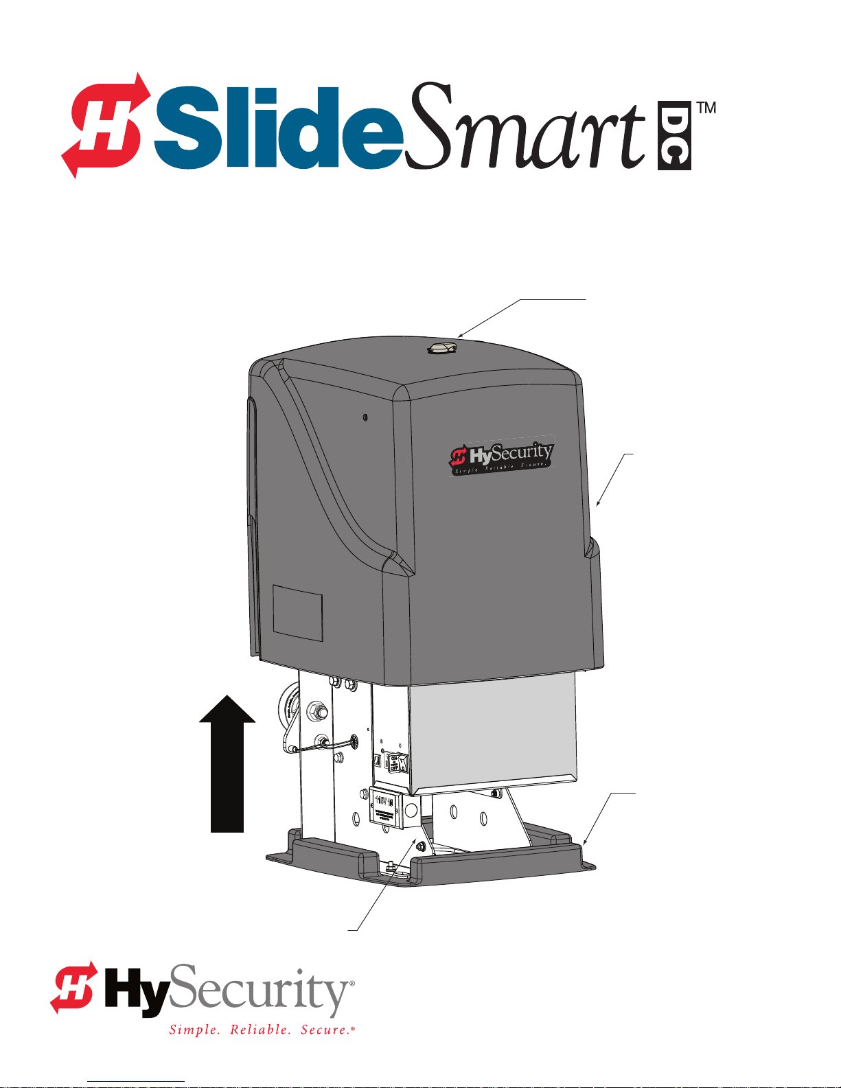
Keyed latch
Cover
Operator
Service Outlet
115VAC, 15A
Plastic base
Unpack
the OperatOr
Page 2
Site Planning and OPeratOr inStallatiOn
WARNING
DANGER
The illustrations and instructions presented in this guide provide a quick
overview of the SlideSmart installation process. For more detailed steps,
refer to the SlideSmart DC Installation and Reference Manual.
IMPORTANT: When installing the operator, be sure to comply
with all local government regulations and codes, and read the
Important Safety Instructions found in the manual.
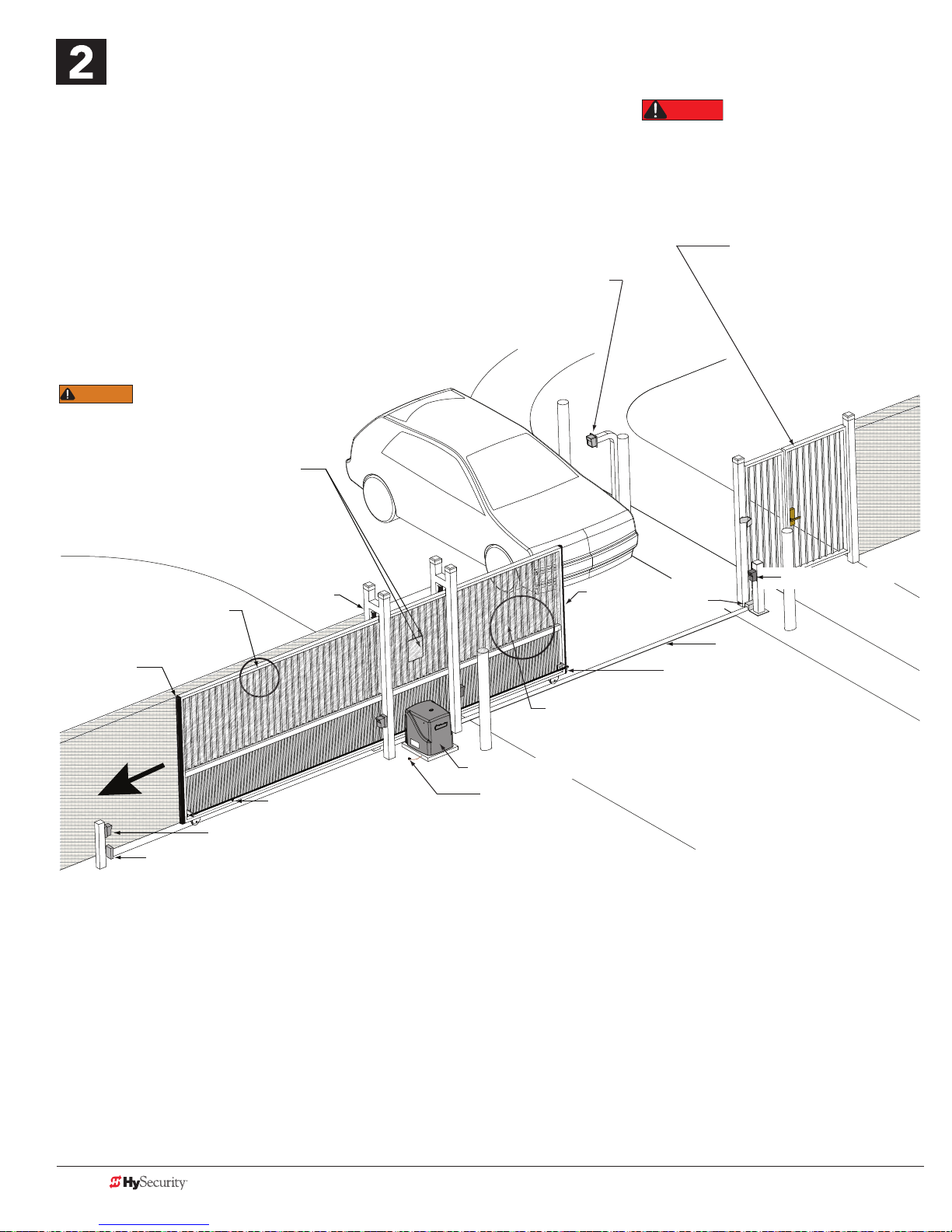
Key or Card reader
Mount access control
devices at least 6ft
(183cm) beyond gate.
Public Side
Be sure to place the
WARNING signs on both
sides of the gate. For your records, take a
photograph of the completed installation site.
attach Warning
SignS
Turn OFF AC power at the source
(circuit breaker panel) before
installing the operator. Follow facility Lock Out /
Tag Out procedures. Make sure both the
DC and AC power switches on the Control Box
are in the OFF position. Refer to step 8.
Pedestrian gate located
near the slide gate
Make sure a separate walkthrough entrance is available
and its pedestrian path is
clearly designated.
Maximum 2¼" (57mm)
width between vertical bars
Edge sensor
on trailing edge
Left Hand Gate
opening
Photo eye (entrapment protection shown in four locations
Physical stop – weld stops at both ends of V track
Non-pinch
rollers (4x)
SlideSmart DC operator
Target magnet on chain
SlideSmart OPeratOrS
SlideSmart dc 15
Duty cycle: continuous
Power, Single phase: Switch selectable
115 volts, 3 amps, 50/60 Hertz
230 volts, 1.5 amps, 50/60 Hertz
Motor: ½ hp
Maximum gate weight: 1500lbs (680kg)
Gate Speed: 1ft/s
Solar Model: SlideSmart DCS 15
NOTE: for SlideSmart DC Solar operates, refer to www.hysecurity.com
SlideSmart dc 10F
Duty cycle: continuous
Power, Single phase: Switch selectable
115 volts, 3 amps, 50/60 Hertz
230 volts, 1.5 amps, 50/60 Hertz
Motor: ½ hp
Maximum gate weight: 1000lbs (454kg)
Gate Speed: 2ft/s
Solar Model: SlideSmart DCS 10F
Earth ground
Edge
sensor
To comply with ASTM F2200, a screened wire mesh extends
to the top of the gate or to a minimum height of 6 ft. (183 cm)
if a 2¼" (57mm) or larger gap exists between the vertical bars.
Physical
stop
V track
Front edge of gate
Photo eye (4x)
Secure Side
Site OvervieW
Recommended Entrapment Protection shown
Page 2 D0349 Rev D SlideSmart DC Quick Start Steps www.hysecurity.com
Page 3

OPeratOr & earth grOund inStallatiOn
DANGER
cOncrete Pad dimenSiOnS
Gate to base mounts
Ideal distance = 5½" (14cm)
5½"
(14cm)
10.5"
(26.7cm)
1.6"
(4.1cm)
Concrete
pad
Area
cut out
for
conduit
6¼" x 12"
(17cm x 30.5cm)
10.4"
(26.4cm)
19" minimum
(48.3cm)
#40 Roller
(53.3cm)
GateChain,
21"
Grade
level
Slotted holes (4x) for
concrete anchors:
½ - 13 x 13½"
mOunt the OPeratOr
Chain to Gate
Ideal distance = 3¼" (8.25cm)
Min. distance = 2½" (5.7cm)
Chain
height
7¾"
(19.7cm)
Concrete pad
Side vieW
NOTE: Operator footprint with covers is
approximately 18" square (45.7cm).
Gate
SlideSmart DC
operator
Consult local
codes for
proper depth
Chain
3
(91.4cm)
Ground
wire
Concrete pad
(depth set per
local codes)
High voltage wires
Main AC power
Grounding rod depth at
10ft (3m) or per local code
Ground
lug
Cut-away
view
Conduit runs
2" (5cm) above
concrete pad
Minimum pad
height is 2" (5cm)
above grade level.
20.7"
(52.6cm)
Side cut-aWay vieW
ShOWS cOnduit
Placement &
grOunding
Grade level
Vehicle loop
control wires
Extra conduit
(Dual/Sequenced gate)
(Conduit may be shared with low voltage wires)
Low
voltage/Communication wires
NOTE: To reduce electrical interference, keep as much distance as possible
between the high voltage and low voltage conduits.
The potential for lightning discharge exists
National Electric Code (NEC) requires a separate earth ground
in addition to the required equipment ground. A local earth
ground also serves to protect the electronic controls.
with all gates, fences and gate operators.
www.hysecurity.com SlideSmart DC Quick Start Steps D0349 Rev D Page 3
Page 4

inStall the chain
Pedestrian gate
Public Side
Trailing edge
of gate
inStall the
chain bracketS
1. Measure for proper chain
alignment BEFORE welding
the brackets to the gate.
Make sure the chain will run
horizontal to the ground
and parallel with the gate.
2. Weld the chain brackets
to gate. Two locations:
front edge and trailing edge.
3. Attach the eye bolts to the
brackets as shown.
4. Attach the connector link to the
chain and eye bolt.
5. Feed the chain around the idler
wheels and over the sprocket.
6. Adjust the nuts on the eye bolt to
tighten the chain and minimize sag.
Chain
bracket
⅛"
Front edge
of gate
Secure Side
Eye bolt
Chain bracket
7¾"
(19.7cm)
inStall and align the chain
Feed chain over sprocket. View illustration in step 7, also.
Connector link
Eye bolt
Measure chain height.
Weld bracket to gate so
chain remains horizontal
and level.
Chain to Gate
Ideal distance = 3¼"
(8.3cm)
NOTE: For rear or post mounted installations, see SlideSmart DC Installation and Reference Manual.
CORRECT INSTALLATION
tOP vieW
Page 4 D0349 Rev D SlideSmart DC Quick Start Steps www.hysecurity.com
Side vieW
Too close to gate
INCORRECT
CORRECT
INCORRECT
INCORRECT INSTALLATION
Page 5

initial SetuP menu
PREV
Connect the red battery wire to its spade terminal. Turn ON DC power.
The USAGE CLASS menu display appears the rst time power is
applied. Five sequential displays present information which must be
congured before SlideSmart will function.
To edit
the MENU
Press SELECT.
Two top
characters blink.
UC 0
USAGE CLASS
CLOSE
OPEN
NEXT
PREV
SH 0
GATE HANDING
CLOSE
OPEN
NEXT
PREV
To navigate through
SELECTIONS
Press NEXT.
Continue pressing NEXT
to view all selections.
MENU
STOP
SELECT
STOP
SELECT
MENU
RESET
RESET
To choose what is
on the display
Press SELECT.
Blinking characters
become static.
To navigate
between menus
Press NEXT or PREV.
Advance – press NEXT
Previous – press PREV
SELECTIONS
0 – No Usage Class set.
1 – Single Family residential up to four units.
2 – Multi-family, hotel, etc.
3 – Industrial use, not for general public.
4 – Guarded and monitored facility not for
general public.
SELECTIONS
0 – No handing set. Gate will not move until
handing is set.
Looking at the gate from the secure, operator
side, choose:
R – If the operator is on your right.
L – If the operator is on your left.
cOnnect the battery
Connect the red battery wire.
ON
DC
POW
OF
Emergency
Stop Button
turn On
dc POWer
RESET
OPEN
CLOSE
NEXT
STOP
SELECT
MENU
SELECTIONS
WT 0
GATE WEIGHT (LB)
0 – Not set.
1 – Gate weight: 0 to 400lbs (0 to 181kg)
OPEN
CLOSE
STOP
MENU
RESET
2 – Gate weight: 401 to 800lbs (182 to 363kg)
3 – Gate weight: 801 to 1100lbs (363 to 499kg)
PREV
4 – Gate weight: 1101 to 1500lbs (499 to 60kg)
SELECT
NEXT
learn limitS
LEARN OPEN
INCHES: +XXX.X
CLOSE
OPEN
NEXT
PREV
Hold the OPEN button until the gate
slides to full open. Release the OPEN
button. Note that if you go too far, you
can press CLOSE to reverse direction.
Press STOP twice to preserve the open
stop location in memory.
STOP
SELECT
MENU
RESET
SlideSmart DC 15 SlideSmart DC 10F
1 – Gate weight: 0 to 400lbs (0 to 181kg)
2 – Gate weight: 401 to 800lbs (182 to 363kg)
3 – Gate weight: 801 to 1100lbs (363 to 499kg)
4 – Gate weight: 1101 to1500lbs (499 to 60kg)
LEARN CLOSE
INCHES: - XXX.X
OPEN
PREV
CLOSE
NEXT
STOP
SELECT
MENU
RESET
Hold the CLOSE button until the gate
slides to full close. Release the CLOSE
button and press STOP twice. The full
close stop is retained in memory.
HYSECURITY
GATE CLOSED
CLOSE
OPEN
SELECT
NEXT
PREV
NOTE: GATE CLOSED appears
on the display and ALERT 15 ashes
until the target magnet is installed
and its location stored in memory.
See page 6, Install the Target Magnet.
STOP
MENU
RESET
www.hysecurity.com SlideSmart DC Quick Start Steps D0349 Rev D Page 5
Page 6

inStall the target magnet
CAUTION
With the gate in the FULL
CLOSE position, mark the
chain link directly opposite
the target sensor.
Use the target sensor
closest to the trailing
edge of the gate.
Target sensor
Public Side
Secure Side
To install the target magnet, take the following steps:
1. With the gate closed, mark the chain link as shown in the illustration above.
2. Press the OPEN button to move the gate and chain a few feet and then press STOP.
3. Turn OFF the DC power switch (leave the AC power switch ON). Performing this step
keeps the gate from moving accidentally while you install the target magnet.
4. Find the mark on the chain link and count about four (4) xed links toward the
operator (approximately 3 inches, 76mm).
Pedestrian gate
When the gate is CLOSED, the target
magnet should stop between the
target sensor and the roller chain sprocket. The target
magnet MUST NOT enter the sprocket teeth.
Screw
Roller chain
Mark on Chain
3"
Target sensor
Install 1 Target Magnet
(large white centerpiece faces sensor
sprocket
Target sensor
(RH gate)
Target
sensor
(LH gate)
(76mm)
Position of the target magnet when
5. Remove the screw from the target magnet.
6. Fasten the target magnet to the chain link as shown in the illustration. Insert the screw and tighten it securely. To avoid damage to
the idler wheel, the head of the screw must be ush with the chain rollers.
7. To allow gate movement, turn ON the DC power switch.
8. Test the application of the target magnet by pressing the CLOSE button. An audible beep is heard the rst time the target magnet
passes the target sensor. The limit sensor light on the Smart DC Controller also ashes red.
NOTE: Use one target magnet and make sure the target magnet activates. Toggle both power switches OFF and ON. The gate will
move. When the target magnet passes the target sensor, limits are automatically restored. If LEARN OPEN appears on the display,
the limits need to be re-established. Return to step 6 on page 5.
the gate is fully closed.
Page 6 D0349 Rev D SlideSmart DC Quick Start Steps www.hysecurity.com
Page 7

turn OFF main POWer and cOntrOl bOx
CAUTION
DANGER
CAUTION
WARNING
SWitcheS, then cOnnect ac POWer
turn POWer OFF
Turn OFF AC power at the source
(circuit breaker panel) before
accessing the wires in the SlideSmart junction box.
Follow facility Lock Out / Tag Out procedures.
Make sure both the DC and AC power switches
are in the OFF position.
Place DC power switch
in the OFF position.
Place AC power switch in
the OFF position.
Service Outlet
DO NOT connect the 115VAC
service outlet to 208 or 230VAC
power supply wires! To use the 115VAC service outlet
on a 208/230VAC installation, the electrician needs to
run an extra neutral wire to the operator from the
power source and wire the service outlet per cover.
O
DC
POW
OF
115VAC wires for the
Service Outlet
Junction
box cover
and label
Junction box
cOnnect the POWer WireS
1. Unscrew the two Phillps-head screws.
2. Remove the cover to the junction box.
3. Connect the AC power and ground wires with wire nuts.
Wiring of gate operators must conform to NEC
standards and comply with all local codes.
O
AC
POW
Service Outlet
OF
115VAC, 15A
Voltage selector switch is
factory set to 115V.
If power input
is 208/230V, move
the switch so 230V
appears and change the
label on the junction box.
When connecting to 208/230VAC on
the AC power, the voltage selector
switch on the AC power board must be moved to the
230V position or damage to the operator will occur
and void the Limited Warranty.
www.hysecurity.com SlideSmart DC Quick Start Steps D0349 Rev D Page 7
Page 8

cOnnect acceSSOrieS
All the accessories require a minimum of two connections on the Smart DC Controller:
a device input
a Common Bus Terminal (COM)
Other devices may require more connections or congurations. For example, the Fire Department (EMERG OPEN)
input requires a +24-volt input. The connection must be activated by changing the settings through the Installer
Menu. Refer to the SlideSmart DC Installation and Reference Manual.
COMMON
TERMINALS
Access controls
(Ex. Card reader, keypad)
Photo eye N.O.
connects to either
EYE OPEN
or EYE CLOSE.
Photo eye
4-wire connecon:
Power COM/+24V
EYE COM
Relay COM
EYE OPEN or CLOSE
(depending on funcon)
Edge
sensor
COM
COM
COM
COM
COM
COM
COM
COM
STOP
OPEN
CLOSE
RADIO
OPEN
PARTIAL
EYE
OPEN
EYE
CLOSE
EXIT
LOOP
BLOCK
EXIT
IN OBS
LOOP
OUT OBS
LOOP
CENTER
LOOP
EDGE
EYE
COM
+ 24 V
EMERG
OPEN
24VDC
24VDC
24VAC
24VAC
12VDC
12VDC
OPEN
SHOW
LEDs
2 channel
radio receiver
Red LED
heart beat
indicates
processor
is working.
Press button
to light active
inputs.
N
PE
O
V
4
2
+
EDGE
TI
P
O
O
DI
A
R
C
ON
O
RS232
B
M
D
S
Multi-colored LED
indicates power and
gate status.
RS485
ethernet
USER RELAY 1
Electro-mechanical
D
2
R
E
S
U
A
M
O
C
AL
U
AT
G
O
C
E
USER RELAY 2
Solid state
HY-5A
FREE EXIT
HY-5A
INSIDE LOOP
HY-5A
OUTSIDE LOOP
HY-5A
CENTER LOOP
C
O
N
M
USB PORT
RS-485
COMMUNICATION
HY-5A
VEHICLE LOOP
Connection for a Dual or Sequential gate system.
See Chapters 2 and 5 in the SlideSmart DC
Installation and Reference Manual.
Page 8 D0349 Rev D SlideSmart DC Quick Start Steps www.hysecurity.com
© 2013
 Loading...