

HySecurity SlideDriver 30F, SlideDriver 80, SlideDriver 50VF 2/3, SlideDriver 40, SlideDriver 50VF 2 Programming And Operations Manual
...Page 1
SlideDriver 15, 30F, 40, 80, 200
and SlideDriver 50VF 2/3
Programming & Operations Manual
with
HySecurity Smart Touch Controller
MX3630-01 Revision B
This document provides Important Safety Information, specications, and references along with
an overview of programming user and installer menu options, designing vehicle loop layouts,
troubleshooting, and maintaining the gate operator.
Page 2

HySecurity Gate OperatOrS: uL 325 – 2016
The following bullet points highlight how your automated gate system sites can monitor external entrapment
protection using HySecurity gate operators:
• Normally Closed (NC) sensors – Before gate movement occurs, the gate operator veries that the
external entrapment protection sensor is connected and fully functional.
• Build Year (BY) – An added menu item distinguishes between pre-2016 manufacturing dates and
UL 325 - 2016 manufacturing dates. Build Year (BY) is a factory-setting. Build Year 2 (BY 2) is the default for
all HySecurity gate operators indicating a manufacturing date of 2016 in the serial number. Replacement
controller boards for existing sites allow for a Build Year setting of 1 (BY 1) (pre-2016).
• Independent Sensor Inputs – The edge, photo eye and photo eye COM inputs on the Smart Touch and
Smart DC Controllers (STC and SDC) have been re-labeled. The same wiring connections become three
independent methods for easy entrapment sensor conguration and normally closed outputs.
Table 1: HySecurity Gate Operators requiring External Monitored Entrapment
Protection Sensors
UL 325 Entrapment Protection Sensor Monitoring Required
HySecurity Gate Operators
(includes Modular, Correctional, and
UPS models)
Build Year
UL 325 - 2016
(set at the factory)
Normally Closed (NC) sensors tested & approved.
Three SENSOR Inputs on Controller.
Installer Menu congurable.
Build Year (BY) factory-set to UL 325 - 2016.
SlideDriver 15, 40, 30F, 50VF 2/3, 80, 200 2
SlideDriver 50VF series 2
SlideSmart DC 15 & DCS 15 2
SlideSmart DC 10F & DCS 10F 2
SwingRiser 14, 14-Twin, 19,
19-Twin, 30, 30-Twin
SwingSmart DC 20 & DCS 20 2
HydraSwing 40, 40F, 40-Twin, 40F-Twin,
80F, 150
HydraLift 10, 10F, 20, 20F 2
2
2
●
●
●
●
●
●
●
●
Table 2: HySecurity Gate Operators maintaining Object Detection
Table 2 indicates those HySecurity gate operators that may be within the exception parameters of UL 325 or
comply with standards other than UL 325, but continue to maintain object detection capabilities. HySecurity
strongly recommends that you assess every site for entrapment zones and provide the necessary protection to
guard against entrapment.
HySecurity Gate Operator's with
Obstruction Protection (Object Detection)
StrongArm (HTG) 14, 20, 28, 36 2
StrongArmCRASH (M30/M50) 2
StrongArmPark DC 10 & DCS 10
StrongArmPark DC 14 & DCS 14
WedgeSmart DC 10 & 10 DCS 2
WedgeSmart DC 14 & 14 DCS 2
HydraWedge SM50 2
Build Year
UL 325 - 2016
2
Sensor Inputs automatically set to "NOT USED"
Installer has option to change settings as site design dictates.
●
●
●
●
●
●
ii MX3630-01 Rev. B SlideDriver/SlideDriver 50VF Series © 2017 www.hysecurity.com
Page 3

Table 3: External Entrapment Protection Sensors Approved for Use with HySecurity
Gate Operators
The site designer or installer must determine which external entrapment protection sensors will be installed
with the gate operator to create a UL 325 compliant installation site.
NOTE: Table 3 provides the list of sensors that are approved for use with HySecurity gate operators using the monitoring
capabilities found in software versions h4.53 or h5.54 (or higher). These sensors are ETL listed or UL recognized to UL 325 and have
been tested and approved by Intertek for use in HySecurity gate operators.
External Entrapment Protection Sensors: Normally Close Contact, Compatible with
HySecurity Gate Operators
P/N 2016 Monitored Sensors Sensor Type Output Manufacturer
MX3981
MX4161
MX3982
MX4161
MX4037
MX4161
MX3985 Reecti-Guard (RG-R) Photo eye, reective Normally Closed Miller Edge Type B1
MX4015
MX3986
MX4013
Wired Gate Edge Sensor
MGR20-2U-05-T2, Round
Gate Edge Module (GEM -204) Edge Interface Module Normally Closed
Wired Gate Edge Sensor
MGS20-2U-05-T2, Square
Gate Edge Module (GEM -204) Edge Interface Module Normally Closed
KIT: Wired Gate Edge Sensor
MGO20-2E-05-T2, Square
and Channel mount
Gate Edge Module (GEM -204) Edge Interface Module Normally Closed
KIT: MGL-K20
(includes MX3986 and MX4013)
Wireless Gate Link
MGL-TX20
Wireless Gate Link
MGL-RX20
Wraparound edge
(5 ft x 2" round post)
Wraparound edge
(5 ft x 2" square post)
Edge (3-sided activation
Slide In Style)
(5 ft x 1½" width)
Wireless Gate Link Normally Closed Miller Edge Yes
Transmitter (battery-
operated, radio control)
Receiver (24VDC, radio
control)
10K Resistor
Miller Edge Type B2
10K Resistor
Miller Edge Type B2
10K Resistor
Miller Edge Type B2
N/A
Miller Edge Yes
Normally Closed
UL 325
Recognized
MX3987 The Solution, MIM-62 Multi-Input Module Normally Closed Miller Edge Yes
MX3990 IRB-MON (Dist.~ 65 ft) Thru-beam photo eye Normally Closed
MX000846 KIT: IRB-325 (Dist.~ 50 ft) Thru-beam photo eye Normally Closed
MX000999 KIT: E3K-R10K4-NR (Dist. ~ 40 ft) Photo eye, reective Normally Closed Omron Type B1
NOTE: Bold type indicate sensors or accessories that must be installed together for external entrapment protection to be properly
monitored.
www.hysecurity.com © 2017 Introduction MX3630-01 Rev. B iii
EMX
Industries
EMX
Industries
Type B1
Type B1
Page 4
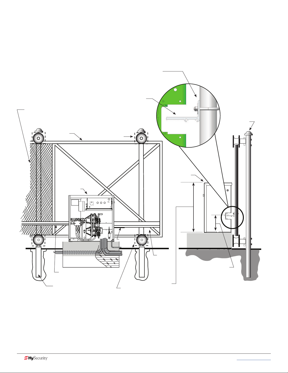
SlideDriver 15, 30F, 40, 80, 200
SlideDriver 50VF Site Installation Overview
Gate Face*
Use shims as needed
Grooved Drive Rail
Screen Safety Mesh on Gate Height: Per UL 325 and ASTM
F2200, all openings in a sliding gate up to a 72-inch (6 foot or
183 cm) height must be guarded or screened.
Support Post
Gate
SlideDriver
Concrete Pad
Drive Rail
Support Post
Wheel Cover
For clarity, safety mesh
is not shown
Limit
Ramp
Wheel Cover
SlideDriver
Drive
Rail
All models:
(except SD 200)
26" (66cm)
SlideDriver 200:
43¼" (109.5cm)
Height from top of
Drive Rail* to bottom
of gate operator.
All models:
9¼" (23.5cm) using
standard
AdvanceDrive™ wheels, 6 or 8 inch.
*NOTE: using XtremeDrive™ wheels, adjust
height along the length of the Drive Rail by
¼ to ½ inch which increases overall height
between 9¾ and 10 inches (24 to 25 cm).
iv MX3630-01 Rev. B SlideDriver/SlideDriver 50VF Series © 2017 www.hysecurity.com
Page 5
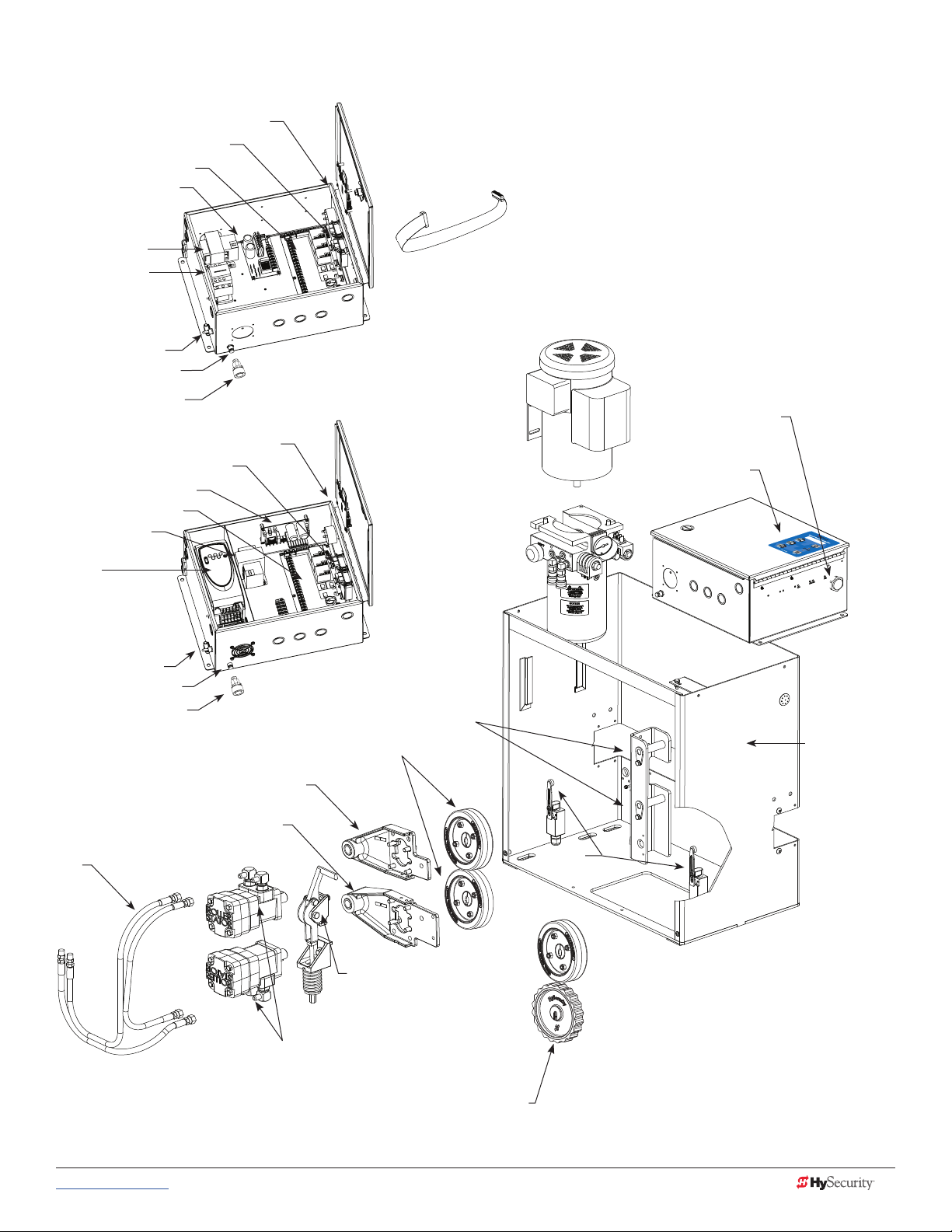
SlideDriver (all models) 50VF Components
UC 2
USAGE CLASS
Board, Display
Detector, Vehicle
Board, Smart Touch
Board, Power Supply
Transformer
Contactor, Motor
Switch, Disconnect
Reset Switch, Internal
Reset Button, External
HY-5A Detector, Vehicle
Board, Power Supply
Board, Smart Touch
Transformer
Variable
Frequency Drive
(VFD) Power Unit
Switch, Disconnect
Reset Switch, Internal
Reset Button, External
SlideDriver Control Box
Board, Display
SlideDriver 50VF Control Box
AdvanceDrive™ Wheel Kit
[Motor, Electric]
[Pump Pack]
Drive Arm, Pivot Kit
Cable, Ribbon
Buzzer, Piezo
Keypad
Chassis
Cover not shown
Drive Arm, Motor Mount, Top
Drive Arm, Motor Mount, Bottom
Hose
Release,
Manual
Motor, Hydraulic
Combination AdvanceDrive
and XtremeDrive Wheels
(80 and 150 Models, only.
Not available on 50VF series)
Limit
Switches
www.hysecurity.com © 2017 Introduction MX3630-01 Rev. B v
Page 6

SlideDriver (all models) 50VF Components
Motor, Electric, DC
Motor, Electric, AC
Contactor, Mercury
Motor Starting Kit
Breather cap
Vent plug
Vent plug
Valve, Braking
Braking Kit
Quick Disconnect, Socket
Valve, Relief
Sensor Kit, Inherent Entrapment
Valve Coil, Quick Stop
Valve, Quick Stop
Valve, Check, Endhead
Gauge, Pressure
AWOG
Valve, 2 Position Directional
Valve Coil, Directional
Reservoir
vi MX3630-01 Rev. B SlideDriver/SlideDriver 50VF Series © 2017 www.hysecurity.com
Page 7

Contents
HySecurity Gate Operators: UL 325 – 2016 ..................................................................................................................... ii
Table 1: HySecurity Gate Operators requiring External Monitored Entrapment Protection Sensors ...........................ii
Table 2: HySecurity Gate Operators maintaining Object Detection .............................................................................ii
Table 3: External Entrapment Protection Sensors Approved for Use with HySecurity Gate Operators ...................... iii
Welcome to HySecurity ...........................................................................................1
Contact Information .........................................................................................................................................................2
Notices and Bulletins .......................................................................................................................................................2
Supplemental Documents ................................................................................................................................................2
IMPORTANT SAFETY INFORMATION .............................................................................................................................3
Safety - Additional Installer Responsibility ....................................................................................................................4
Identifying Gate Operator Category and Usage Class ....................................................................................................5
Safety - Additional Installer’s Responsibility, continued ................................................................................................6
Safety - Owner/User Responsibility ...............................................................................................................................7
Hazardous Materials and Proper Disposal .......................................................................................................................7
Emergency Stop Button ..................................................................................................................................................8
Emergency Release .........................................................................................................................................................8
Safety Notices ..................................................................................................................................................................9
Common Industrial Symbols ............................................................................................................................................9
PoWer ..................................................................................................................11
Installing the Earth Ground ...........................................................................................................................................11
Site Considerations .....................................................................................................................................................12
Wiring AC Power ............................................................................................................................................................12
Turning the Power Switch ON .....................................................................................................................................13
Wire Sizing and Runs ......................................................................................................................................................14
Low Voltage Control Wiring ........................................................................................................................................14
SlideDriver Wiring Charts (Incoming Power) ...............................................................................................................15
SlideDriver 50VF-series Wiring Chart (Incoming Power) .............................................................................................17
Performance of 50VF-series Operators on 1 and 3 Phase, 50 or 60Hz.......................................................................17
Control Transformer Connections (Non-UPS) ...............................................................................................................19
Gate Operator Connections (Modular Unit) ..................................................................................................................19
DC Power Supply (UPS) Connections .............................................................................................................................20
AC Power Supply with HyInverter AC ............................................................................................................................20
initial SetuP ..........................................................................................................21
Gate Handing .................................................................................................................................................................21
Hydraulic Hose Swap .....................................................................................................................................................22
Adjusting the Brake Valves ............................................................................................................................................22
www.hysecurity.com © 2017 Table of Contents MX3630-01 Rev. B vii
Page 8

Grounding, Breather Cap Installation & Handing .........................................................................................................23
SlideDriver Slow Down Limit Ramps ...........................................................................................................................24
Adjusting the Pressure Relief Valve ................................................................................................................................25
ModBus RTU in SlideDriver 50VF-series ........................................................................................................................26
Emergency Fast Operate (EFO) in SlideDriver 50VF-series ...........................................................................................27
Installing a Push Button Device for Emergency Fast Operate (EFO) ............................................................................28
Emergency Fast Close Speeds ...................................................................................................................................28
entraPment Protection .........................................................................................29
Manufacturer’s responsibility ..........................................................................................................................................29
Pressure Relief Valve – All Hydraulic Operators: ........................................................................................................29
Inherent Entrapment Sensor System – Hydraulic Operators (IES) ..............................................................................30
The Inherent Entrapment Sensor (IES) ..........................................................................................................................30
How Software Handles Monitoring External Entrapment Protection Sensors ...............................................................31
Table 4: Changes to Sensor Inputs on the Controller .................................................................................................31
External Entrapment Protection Sensors: What the Installer Needs to Do ....................................................................31
Table 5: Installer Menu Settings for SENSOR Inputs ..................................................................................................33
Supply Power to the Sensors .........................................................................................................................................34
control Panel overvieW .......................................................................................35
SlideDriver Wiring Diagram, D0266 REV B ....................................................................................................................36
Variable Speed Drive (VFD) Control Box .......................................................................................................................37
Variable Speed Drive Wiring Diagram ...........................................................................................................................38
STC Board, Power Supply Board and Display ................................................................................................................39
DiSPlay & menu oPtionS ........................................................................................41
Initial Setup ....................................................................................................................................................................41
Understanding the Display and Keypad .......................................................................................................................41
Menu Mode and the STC Keypad ................................................................................................................................42
Menu Mode Navigation .................................................................................................................................................42
Run Mode and the STC Keypad ...................................................................................................................................43
Viewing Operator Status Displays ..................................................................................................................................43
Stop the Status Display Scrolling ................................................................................................................................44
Change the Contrast on 7 Segment Displays .............................................................................................................44
Check the Software Version ........................................................................................................................................44
Check Time and Date .................................................................................................................................................45
User Menu ......................................................................................................................................................................45
User Menu: Table 6 ........................................................................................................................................................46
Installer Menu ................................................................................................................................................................48
Installer Menu: Table 7 ...................................................................................................................................................48
Setting the Close Timer .................................................................................................................................................54
Test the Operator ...........................................................................................................................................................55
viii MX3630-01 Rev. B SlideDriver/SlideDriver 50VF Series © 2017 www.hysecurity.com
Page 9

Stc inPutS & Wiring .............................................................................................57
Overview of the STC and Power Supply Board ..............................................................................................................58
Integrating with Security Systems and HyNet™ Gateway .............................................................................................59
Smart Touch Controller Inputs........................................................................................................................................60
STC Terminal Inputs .......................................................................................................................................................60
User Relays – Programming Procedure ..........................................................................................................................63
Programmable User Relays: Table 8............................................................................................................................63
Hy8Relay Module Option ...............................................................................................................................................66
Bi-Parting & Dual gate SyStemS ............................................................................67
Connecting an Interlocked Pair (Dual Gate) ...................................................................................................................67
Dual Gate Wiring Connections ...................................................................................................................................68
Dual or Sequenced Gates: Power, Software & Accessory Requirements ..................................................................69
Programming a Dual Gate (Interlocked Pair) .............................................................................................................69
Connecting Sequenced Gates .......................................................................................................................................70
Sequenced Gate: Conguration #1 ...............................................................................................................................72
Sequenced Gate: Conguration #2 ...............................................................................................................................73
veHicle Detector
inStallation anD logic ...........................................................................................75
Anti-TailGate Mode (Closing Logic) ............................................................................................................................75
TailGate Alert .............................................................................................................................................................75
Vehicle Detector Installation: HY-5A ..............................................................................................................................76
Connecting HY-5A Vehicle Detectors .............................................................................................................................77
View Call Level in Real Time .......................................................................................................................................78
Installing Standard 11-Pin Box Type Vehicle Detectors ..................................................................................................79
PHoto eye inStallation ..........................................................................................81
Photo Eyes (Non-Contact) Installation ...........................................................................................................................82
Compatibility ..............................................................................................................................................................82
Installation ...................................................................................................................................................................82
Conguration ..............................................................................................................................................................83
Photo Eye Connections: Smart Touch & Smart DC Controllers ..................................................................................83
Photo Eye Function .....................................................................................................................................................83
Retro-Reective Photo Eye Systems ..................................................................................................................84
Using Photo Eye Sensors instead of Vehicle Loops ......................................................................................................85
Photo Eye Alignment Feature .......................................................................................................................................86
inStalling gate eDge SenSorS.................................................................................87
Compatibility ..............................................................................................................................................................88
Installation ...................................................................................................................................................................88
Gate Edge Function ....................................................................................................................................................88
www.hysecurity.com © 2017 Table of Contents MX3630-01 Rev. B ix
Page 10

trouBleSHooting ...................................................................................................89
System Diagnostic Messages .........................................................................................................................................89
Troubleshooting Codes: Table 9 .................................................................................................................................90
Access the Event Log through the User Menu ..............................................................................................................95
Electrical Issues ..............................................................................................................................................................96
AC-Powered Gate Operators ......................................................................................................................................96
Mechanical Issues ...........................................................................................................................................................97
Hydraulic Issues ..............................................................................................................................................................97
Typical Problems and Troubleshooting Procedures .......................................................................................................98
general maintenance ...........................................................................................99
Smart Touch Analyze and Retrieve Tool (S.T.A.R.T.) .......................................................................................................99
What You Need ...........................................................................................................................................................99
Installing S.T.A.R.T. Software .......................................................................................................................................99
Software Maintenance ..................................................................................................................................................100
Electrical Controls ........................................................................................................................................................100
Clock Battery Replacement ......................................................................................................................................100
Mechnical Controls.......................................................................................................................................................101
Stopping the Gate ...................................................................................................................................................101
Starting the Gate .....................................................................................................................................................101
Mechanical Maintenance .............................................................................................................................................101
Drive Rail ...................................................................................................................................................................102
Drive Wheel Spring Tension (Adjustment of Manual Release) ..................................................................................103
Grooved Drive Rail ...................................................................................................................................................104
Drive Wheel Assembly ..............................................................................................................................................105
Hydraulic System Maintenance ....................................................................................................................................106
Brake Valve Adjustments .........................................................................................................................................107
Pressure Relief Valve Adjustments ............................................................................................................................107
Open Valve ...............................................................................................................................................................107
SlideDriver Operator Maintenance Schedule ..............................................................................................................108
Wiring HySecurity SenSorS: Smart toucH .............................................................109
Wiring Tips for SENSOR COM Terminal: Smart Touch ................................................................................................110
Menu Mode Navigational Tips .....................................................................................................................................110
Smart Touch: Wired Edge Sensor with GEM (-104)......................................................................................................111
Smart Touch: Photo Eye Thru Beam (EMX IRB MON) ..................................................................................................112
Smart Touch: Photo Eye / Reective (E3K R10K4) .......................................................................................................113
Smart Touch: The Solution, MIM-62 (Multi-input Module) ...........................................................................................114
Smart Touch: Photo Eye / Reecti-Guard (RG-R) ..........................................................................................................115
Smart Touch: Wireless Edge, Wireless Gate Link .........................................................................................................116
Smart Touch: Wired Edge with GEM-104 & Photo Eye ...............................................................................................117
Smart Touch: WireLess Edge Gate Link & Photo Eye ..................................................................................................118
SlideDriver Installer Checklist .......................................................................................................................................119
Specications ...............................................................................................................................................................120
x MX3630-01 Rev. B SlideDriver/SlideDriver 50VF Series © 2017 www.hysecurity.com
Page 11
Welcome to HySecurity
Thank you for purchasing our premium SlideDriver™ gate operator. HySecurity Gate, Inc. has manufactured
some of the nest, sturdiest, most innovative, and reliable hydraulic gate operators since the 1970s. We use the
same hydraulic technology common in the aircraft industry while incorporating software capabilities that far
exceed the competition.
All operator designs are tested for hundreds of thousands of cycles before being released to the market. Slide,
swing, trafc barrier, fortied crash barrier and vertical lift operators have all received rigorous testing and
certication. Security, low maintenance, exible conguration, and overall toughness are the foremost criteria
for all HySecurity products.
Our commitment to quality and innovation will become evident as the features and performance of the
expertly engineered and manufactured SlideDriver become familiar to you. Thank you again for the condence
you’ve shown in becoming part of the HySecurity family and in choosing a premium, industry-leading product.
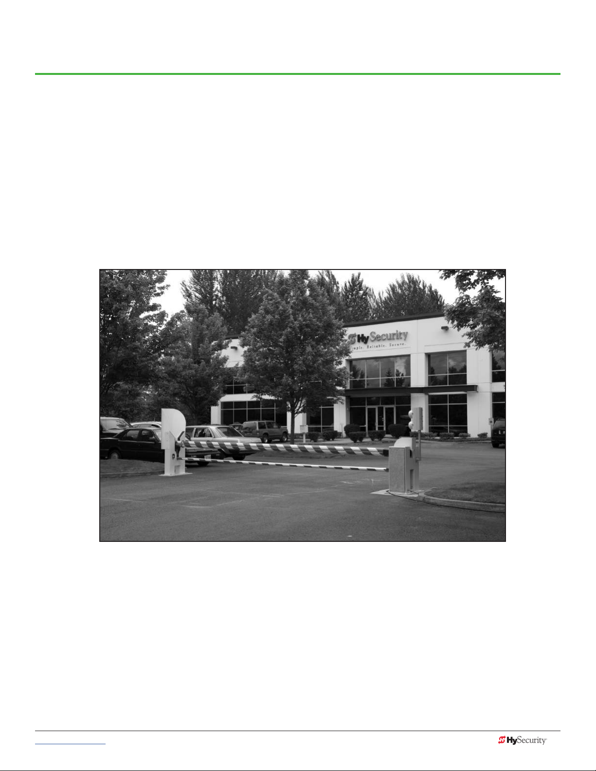
HySecurity Gate, Inc. Headquarters in Kent, WA
www.hysecurity.com © 2017 Important Safety Information MX3630-01 Rev. B 1
Page 12

cOntact infOrmatiOn
Qualied HySecurity distributors are experienced and trained to assist in resolving any problems. For the name
of a qualied distributor near you, call HySecurity at 800-321-9947.
Before contacting your distributor or HySecurity Technical Support, obtain the serial number of your operator.
For information about HySecurity training for installers, maintenance personnel, and end users, refer to the
company website at www.hysecurity.com.
nOticeS and BuLLetinS
Installers should visit HySecurity’s online Technical Support page at www.hysecurity.com or contact HySecurity
prior to installing product to make sure they have received the most up-to-date information.
SuppLementaL dOcumentS
The product literature is comprehensive and contains information needed to plan, install, operate and maintain
your gate operator. Additional general information concerning HySecurity gate operators can be obtained
from the following:
• The gate safety section of the HySecurity website contains published materials regarding industry
changes due to UL 325 - 2016 requirements involving external entrapment protection sensors.
• Links to the product catalogs, product order form, operator manuals, operator software downloads,
technical support bulletins and other useful information.
• S.T.A.R.T. User’s Guide (D0049) - Smart Touch Analyze and Retrieve Tool - details the extensive
software, diagnostic and troubleshooting capabilities of the Smart Touch Controller board.
• DC Power Supply with HyCharger DC, supplement
• AC Power Supply with HyInverter AC, Installation and Reference Manual
• Technical Bulletins (as applicable).
NOTE: Technical Bulletins are automatically issued to registered users of HySecurity products. The product
warranty registration card can be lled out online at www.hysecurity.com.
2 MX3630-01 Rev. B SlideDriver/SlideDriver 50VF Series © 2017 www.hysecurity.com
Page 13

impOrtant Safety infOrmatiOn
WARNING
Read all the product safety information prior to installation. Automatic gate operators move the gate with high
force and can cause serious injury and death! Make sure the automatic gate operator is installed to reduce the
risks of entrapment. Verify the gate operator is installed to comply with all safety standards and local and federal
regulations.
Understand that you as the site designer, installer, maintenance crew, or owner/user must consider the risks
associated with automatic gate operators. Hazards exist with automatic gate operators and can be reduced
with proper gate site design, installation and use. Installers, maintenance crews, and owners/users must
take responsibility to read and follow the safety requirements and Important Safety Information found in the
HySecurity product manuals and review all the literature that accompanies the product.
It is important that only qualied installers handle the installation of the HySecurity equipment and gate
operator. A “qualied” installer has one of the following:
• A minimum of three years experience installing similar equipment
• Proof of attending a HySecurity Technical Training seminar within the past three years
• Signicant manufacturer endorsements of technical aptitude in automatic gate operator installation
and operation
Underwriter Laboratories (UL) and the American Society for Testing and Materials (ASTM) are responsible for
current safety standards and regulations regarding automatic vehicular gate operators. To pass certication, all
aspects of gate operator and gate installation must comply with the appropriate safety standards.
For the most up-to-date ASTM F2200 Gate and Fence Standards, refer to www.astm.org.
For UL 325 Standard of Safety, refer to www.ul.com.
SAVE THESE INSTRUCTIONS
www.hysecurity.com © 2017 Important Safety Information MX3630-01 Rev. B 3
Page 14

impOrtant Safety infOrmatiOn
WARNING
A moving gate or barrier arm, bollard, or wedge can cause serious injury or death.
To reduce the risk of injury or death:
1. READ AND FOLLOW ALL INSTRUCTIONS. Read the gate operator’s product manual and review all the product
labels and literature prior to installing, operating, or maintaining the automatic gate operator.
2. Never let children operate or play with gate controls. Keep all remote controls, especially radio transmitters, away
from children. Do not allow children to play on or around the gate or gate operators.
3. Always keep people and objects away from the gate. NO ONE SHOULD CROSS THE PATH OF THE MOVING
GATE. Start the gate operator only when a gate’s travel path is clear.
4. Test the gate operator monthly. The gate MUST reverse on contact with a rigid object or stop when an object
activates the non-contact sensors. After adjusting the force or the limit of travel, retest the gate operator. Perform
routine tests of the entrapment protection sensors, such as photo eyes and gate edges. Failure to adjust and
retest the gate operator properly can increase the risk of injury or death.
5. Use the emergency release only when the gate is not moving.
6. KEEP GATES PROPERLY MAINTAINED. Read the product manuals. Have a qualied service person make repairs
to gate hardware and replace batteries in accessory or entrapment sensory devices on a regular basis.
7. The automated gate entry is for vehicle use only. Pedestrians must use a separate entrance. Make sure a separate
walk-through entrance is nearby. Make certain a clear pedestrian path is designated and signs direct pedestrians
to the walk-through gate.
8. Install the supplied WARNING signs on the inside and outside of the gate or barrier gate/operator so they are
clearly visible from both the secure and public sides. Installing the signs is a requirement for UL 325 compliance.
9. Use monitored sensors for protection against entrapment as specied in the current UL 325 Standard of Safety.
Safety - Additional Installer Responsibility
• The gate operator must be properly grounded and the incoming power voltage must match the voltage label on
the junction box.
• Verify and install an automatic gate operator per its usage class and only on gate sites that comply with ASTM
F2200 Gate and Fence Standards. See Identifying Gate Operator Category and Usage Class on page 5.
Screen or enclose openings in the gate and install sensors to monitor potential entrapment areas per UL 325
Standard of Safety, which includes:
• All horizontal slide gates must guard or screen openings from the gate’s base support to a minimum height of
6 feet (183 cm) above the ground. This must prevent a sphere of 2¼ inches (57 mm) in diameter from passing
through an opening in the gate or the adjacent fence that is covered in the gate’s open position.
• Physical stops must exist in the gate construction to prevent over-travel in both directions and, for slide gates,
guard posts must be installed to prevent the gate from falling in the event of a roller failure. Exposed rollers
must be capped to avoid potential entrapment.
• Make sure all exposed pinch points are eliminated or any exposed pinch points, rollers and wheels are
guarded.
• External entrapment protection sensors must be used wherever the risk of entrapment exists.
SAVE THESE INSTRUCTIONS
4 MX3630-01 Rev. B SlideDriver/SlideDriver 50VF Series © 2017 www.hysecurity.com
Page 15
identifyinG Gate OperatOr cateGOry and uSaGe cLaSS
Gate operators are given a usage class according to UL 325 Standard of Safety. The usage class is determined
by the area that the vehicular gate operator services.
Four different vehicular usage classes are dened by UL 325:
Class I
Class I: Intended for use in garages or parking areas associated with a residence
of one to four single families.
Class II
Class II: Intended for use in a commercial location or building such as a multifamily housing unit (ve or more single family units) hotels, garages, retail stores
or other buildings accessible by or servicing the general public.
Class III
Class IV
Class III: Intended for use in an industrial location or building such as a factory
or loading dock area or other locations NOT accessible by or intended to
service the general public.
Class IV: Intended for use in a guarded industrial location or building such as
an airport security area or other restricted access locations, NOT servicing the
general public, in which unauthorized access is prevented via supervision by
security personnel.
SAVE THESE INSTRUCTIONS
www.hysecurity.com © 2017 Important Safety Information MX3630-01 Rev. B 5
Page 16

impOrtant Safety infOrmatiOn
Safety - Additional Installer’s Responsibility, continued
• Before attaching the operator to the gate, move the gate or barrier gate in both directions. Make sure it is level
and moves freely. A gate or barrier gate that moves easily reduces strain on operator components. Gravity should
play no part in the opening or closing of a slide gate.
• Never over-tighten a clutch or pressure relief valve to compensate for a stiff or damaged gate.
• Reduce the risk of entrapment throughout the entire travel path by making sure the gate is installed in a location
which ensures the required clearance between the gate and adjacent structures when opening or closing. On
slide gates, minimize the parallel gap between the gate and the fence.
• Install the gate operator on the secure (non-public) side of the gate. Note that swing gates cannot open into
public areas.
• Install external entrapment protection sensors so pedestrians are protected from entrapment in both directions
of gate travel and all hazard areas are fully protected. On hydraulic gates, set the pressure relief valve at the
lowest allowable setting that will reliably operate the gate. The pressure relief valve controls the applied
force of the operator and the sensitivity of the inherent entrapment sensor (IES). Note that no IES exists in the
StrongArm.
• Never disable the Warn Before Operate buzzer. This buzzer provides an alert that the gate is about to move.
• Mount access control devices beyond reach of the gate. The control devices that operate the gate must:
• Be mounted beyond 6 feet (183 cm) of the gate to prevent users from touching or accessing the gate while
operating the controls. People attempting to access the controls by reaching through or around the gate can
be seriously injured or killed by the moving gate.
• Incorporate a security feature to prevent unauthorized use.
• Connect radio and other remote access (non-resetting controls) to the RADIO OPTIONS terminal.
• Be located in a clear line of sight to the gate. Locate access controls (Open, Close, Stop/Reset) where a user
will have a clear view of the gate.
NOTE: An exception for Emergency Access Control devices exists. An EAC device accessible by
authorized personnel only (e.g. re, police, EMS) may be placed at any location within the line-of-sight.
• Open and close the gate to conrm that it was properly installed and to ensure monitoring sensors are working
correctly. Verify the clearance between the gate and adjacent structures per UL 325 Standard of Safety. Have a
qualied technician test the gate monthly.
• When you complete the installation, demonstrate the safety features and operation of the gate operator to the
end user:
• Clearly explain and demonstrate the consequences of removing or defeating any of the safety features.
• Remove the operator cover(s), and then turn the power on and off.
• Manually release the gate. (Use the manual release only when the gate is NOT moving.)
• Use the Emergency Stop Button. (If an emergency stop button is not available, show the user where the Stop
button is located on the gate operator.)
NOTE: Gate operator instructions must be given to the owner per UL 325 Standard of Safety.
• Take photographs of the completed installation site and save it in your business les.
SAVE THESE INSTRUCTIONS
6 MX3630-01 Rev. B SlideDriver/SlideDriver 50VF Series © 2017 www.hysecurity.com
Page 17

impOrtant Safety infOrmatiOn
CAUTION
Safety - Owner/User Responsibility
As the owner/user, you are responsible for the correct and safe installation, operation and maintenance of the
SlideDriver gate operator. It is of the utmost importance that you read and follow the specic instructions and
precautions found in the IMPORTANT SAFETY INFORMATION addressed in this manual. In addition, you must
adhere to the safety standards of applicable federal, state, and local safety regulations, industry standards,
and/or procedures.
NOTICE: For installations outside the United States, make sure that you follow the applicable international,
regional, and local safety standards.
• Automatic gates are for vehicular use only; provide and maintain walkways and signs to direct pedestrians to a
separate walk-through entrance.
• An automatic gate can start at any time without warning; always keep people away from the gate area.
• Never let children operate or play with gate controls. Keep all remote controls, especially radio transmitters, away
from children. Do not allow children to play on or around the gate, gate area, or
gate operators.
• Learn how to turn the power on and off. Learn how to manually operate the gate.
• WARNING signs supplied with the gate operator must remain installed and clearly visible on both sides of the
gate. The signs are required to maintain UL 325 compliance.
• Do not physically disable the warning buzzer and NEVER disconnect or cut its wires. The buzzer provides
compliance with the Manual on Uniform Trafc Control Devices (MUTCD) standards. Disabling the warning
buzzer may increase the risk of death or serious injury.
• Do not remove entrapment protection sensors or any other safety features.
• Have a professional gate installer routinely inspect the gate hardware and test the entrapment protection sensors
and overall gate operation. Have a qualied service person make repairs to gate hardware and equipment to
keep the gate running smoothly.
HazardOuS materiaLS and prOper diSpOSaL
Be aware of the international, federal, and local codes in your area and how best to handle hazardous waste
materials.
The pump pack uid, found in all hydraulic HySecurity operators, can be recycled. Gear oil, found in HySecurity
electromechanical gate operators, can also be recycled. If the uids are mixed or contaminated with any
solvents or other chemicals, they become hazardous waste. Hazardous waste requirements for storage and
disposal must be followed.
If the gate operator has a battery backup system, the batteries contain materials that are considered hazardous
to the environment. Proper disposal of the battery is required by federal law. In the U.S.A., refer to federal EPA
guidelines for proper hazardous waste disposal.
SAVE THESE INSTRUCTIONS
www.hysecurity.com © 2017 Important Safety Information MX3630-01 Rev. B 7
Page 18
emerGency StOp ButtOn
WARNING
WARNING
Make sure all users of the gate know where the emergency stop
button is located (see illustration). It complies with UL 325 Standard
of Safety requirements.
Pressing the emergency stop button while the gate is opening or
closing disables the automatic close timer and stops gate travel.
Gate travel remains stopped until the operator receives another
open or close signal.
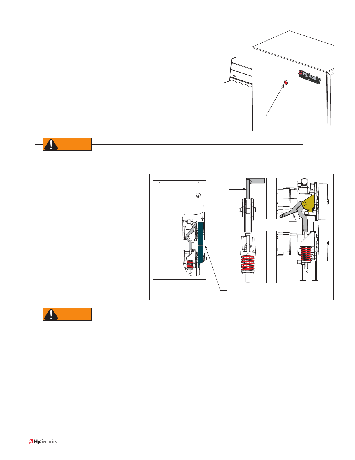
emerGency reLeaSe
Before attempting a manual release, the gate cannot be moving and the power must be disconnected.
Make sure and teach all users how to turn
off electric power, how to move the gate
manually, and how to release the drive
wheels.
Know the weight of the gate you are moving.
Excessively heavy gates can be difcult
to move and may cause serious injury to
those involved in moving the gate. Take
the necessary precautions when manually
moving any gate.
Toggle Handle
clamped
Drive
Wheels
Emergency Stop
button
Toggle Handle
unclamped
To disengage the drive wheels from the drive
rail and manually move the gate, take the
following steps:
1. Remove the front chassis cover and
set it aside.
When releasing the handle inside the chassis, be careful as the mechanism is spring-loaded and drops
rapidly. Hold the handle appropriately so your ngers do not get injured or pinched.
Drive Rail slides between
drive wheels
2. Pull the toggle handle down. The manual release is located under the electric control panel and to the
right of the hydraulic motors.
NOTE: For more information, refer to Drive Wheel Spring Tension (Adjustment of Manual Release) on page 101.
Other types of release mechanisms exist. For example, the Fire and Emergency Access Lock Box is available
through HySecurity distributors. Contact your distributor for more information.
8 MX3630-01 Rev. B SlideDriver/SlideDriver 50VF Series © 2017 www.hysecurity.com
Page 19
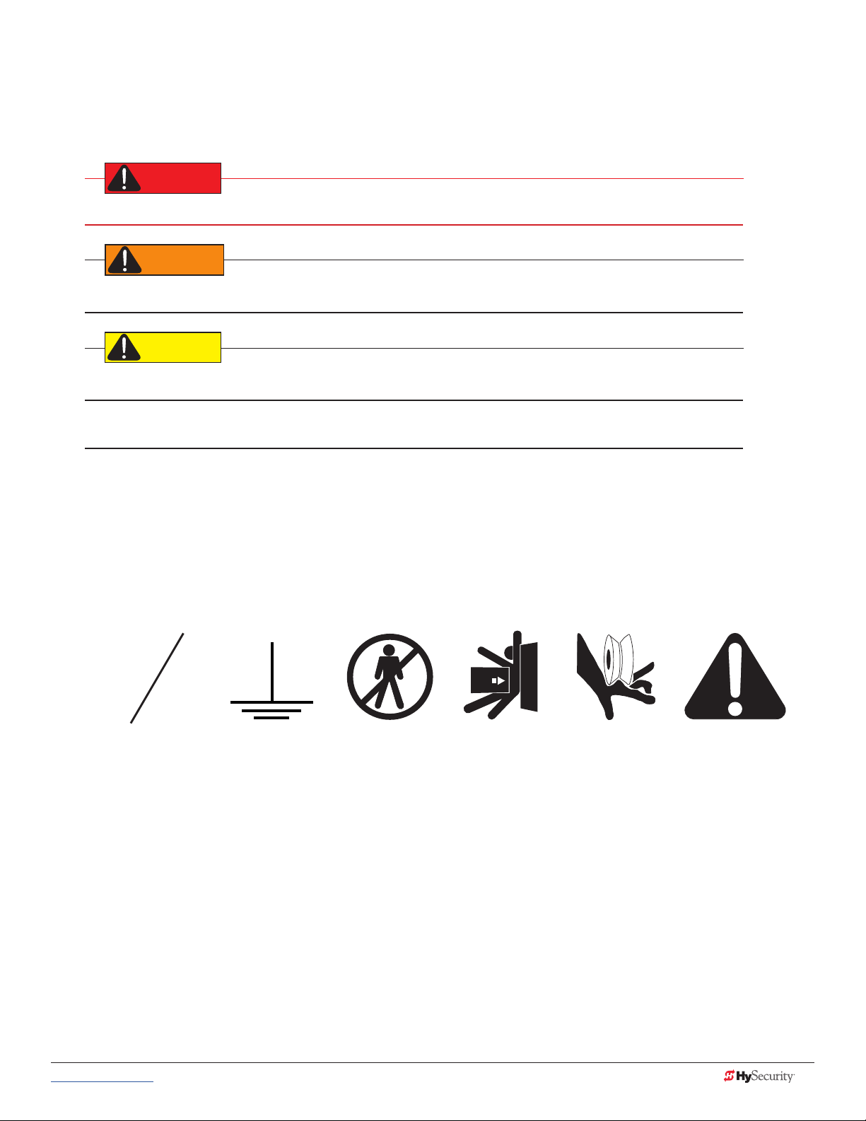
Safety nOticeS
DANGER
WARNING
CAUTION
The following four levels of safety notices are used where applicable within this manual; each notice contains
information specic to the situation.
Indicates death or serious injury will occur if the hazardous situation is not avoided.
Indicates death or serious injury could occur if the hazardous situation is not avoided.
Indicates mild or moderate injury could occur if the hazardous situation is not avoided.
NOTICE: Indicates damage to equipment is probable if the hazardous situation in not avoided.
cOmmOn induStriaL SymBOLS
The following international safety symbols may appear on the product or in its literature. The symbols are used
to alert you to potential personal injury hazards. Obey all safety messages that follow these symbols to avoid
possible injury or death.
O
Electrical Phase
Symbol
Ground
Symbol
- Danger -
Keep Away
Entrapment
Zone
Possible
Pinch Point
Attention
- Take Note -
www.hysecurity.com © 2017 Important Safety Information MX3630-01 Rev. B 9
Page 20

Page intentionally left blank
10 MX3630-01 Rev. B SlideDriver/SlideDriver 50VF Series © 2017 www.hysecurity.com
Page 21
Power
DANGER
How to wire the operator is presented in the Installation Instructions, but detailed information about the earth
and equipment ground, wiring to AC power and the availability of UPS systems are described in this section.
Supplemental documents to this section include:
• DC Power Supply with HyCharger DC • AC Power Supply with HyInverter AC
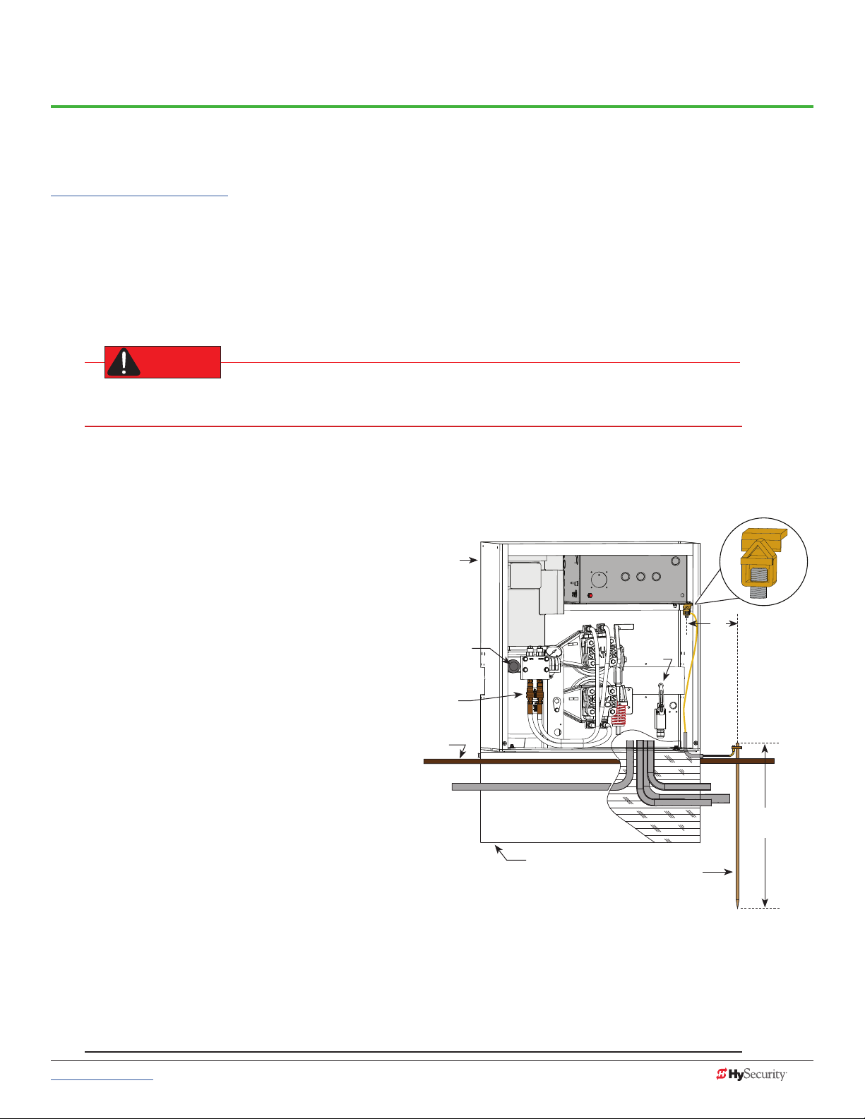
inStaLLinG tHe eartH GrOund
An earth ground refers to the grounding rod and accompanying equipment ground which need to be installed
to safeguard against potential electrical shock and damage to personnel and equipment.
The potential for lightning discharge exists with all gates, fences and gate operators. National Electric
Code (NEC) - Article 250 requires a separate earth ground in addition to the required equipment ground.
HySecurity recommends grounding the operator with a separate earth ground rod (or a similar device
in the case of crash products) to shield the operator against electromagnetism and other electrical signals that
may cause, erratic operation with, or damage to, the Smart Touch Controller and other electrical parts.
For earth grounding requirements in the U.S.A.,
refer to the National Fire Protection Association
(NFPA) 780 - Standard for the Installation of
SlideDriver
Chassis
Control Box
Lightning Protection Systems. Highlights of the
standard include:
• The ground rod must be UL listed
copper-clad steel, solid copper, hotdipped galvanized steel, or stainless
steel. Minimum requirements: ⅝ inch
(16 mm) diameter and 8 feet (244 cm) in
Breather Cap
Quick
Disconnects
Toggle Handle
Limit
Switch
3 ft
(91.4 cm)
Maximum
distance
length.
• The ground rod is driven into the earth
Grade
level
(refer to local codes for proper depth
requirements).
• The ground rod is electrically bonded
to the chassis with a single length of
Cut-away view
un-spliced 6 AWG copper wire less than
3 feet (91 cm) long. Due to the large
concrete foundation on crash products,
Concrete foundation
Earth ground
make the necessary adjustments
to accommodate for earth ground
requirements.
• Local jurisdictions may impose other requirements above the NEC, Article 250 and NFPA 780. Consult
the local codes and regulations regarding requirements in your area.
Ground lug
Consult local
codes for
proper depth
NOTICE: Properly grounding the gate operator is critical to gate operator performance and the life of its
electrical components. Use sufcient wire size during installation. If you do not ground the operator with a
separate earth ground, you risk voiding the HySecurity Warranty.
www.hysecurity.com © 2017 Power MX3630-01 Rev. B 11
Page 22

Site Considerations
WARNING
HySecurity gate operators are intended for permanent installation. Make sure you prepare the site with the
following considerations:
• Make sure all electrical wiring is properly routed via conduits.
• Check the distance of the wiring run from the main panel to the gate operator. Make sure the wire size
of the branch circuit supplying power to the gate operator is large enough to avoid excess voltage
drop. Refer to Wire Sizing and Runs on page 14.
• Make sure the available power source matches the electrical requirements specied on the voltage
nameplate.
Each gate operator is built to run on a specic line power voltage and phase. Failure to ensure the source voltage,
phase and frequency match what is specied for the equipment, may result is severe damage to the equipment.
• Make sure a 20-amp circuit (minimum) protected with a 20-amp Inverse Time Breaker is provided for all
AC power connections.
• Verify that the operator is electrically grounded per NFPA 780 and NEC Article 250 and local codes.
WirinG ac pOWer
The SlideDriver has separate Installation Instructions that explain how to connect to AC power. For reference
purposes, the same information is provided below.
In-rush Current: The current needed to start the electric motor spinning in the proper direction (CCW). It may
take as much as 6 to 9 times the in rush current to start one of the heavy duty operators.
NOTE: Use a 20A (minimum) slow kick (thermal) circuit breaker for all AC motors.
Size the primary wires. Consider the voltage, horsepower, and length of the wire run from the main power
panel.
Make sure you have the proper voltage and conversion of voltage taps at the motor and transformer.
DANGER
Turn OFF AC power at the source (circuit breaker panel) before accessing the wires in the SlideDriver.
Follow facility Lock Out/Tag Out procedures. Make sure all power switches are in the OFF position. Follow
all electrical code standards and regulations.
12 MX3630-01 Rev. B SlideDriver/SlideDriver 50VF Series © 2017 www.hysecurity.com
Page 23
1. Connect to Power: Three wires and a ground are available for connection to a 3 Phase power source
WARNING
15
OUTSIDE
OBSTR
NO
(3Ø). Loosen the screws on the power supply board to open the wire slots at the top and bottom.
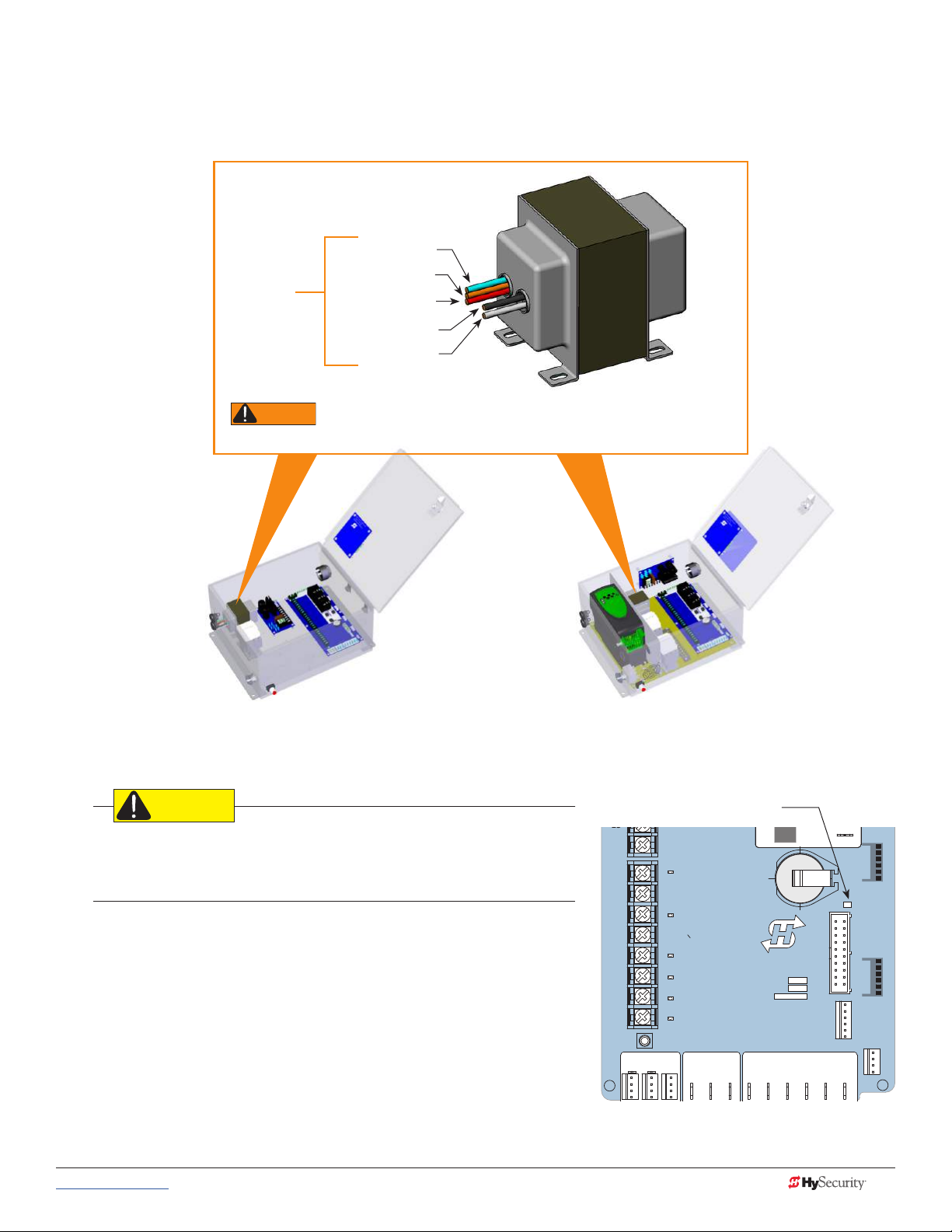
2. Connect AC Power: Place the incoming power wires into their appropriate slots. Attach the ground
wires to the chassis. A wiring diagram is provided in the appendix.
Blue - 460 VAC
Orange - 240 VAC
Input taps
connection wires match the voltage found on the operator’s nameplate.
Red - 208 VAC
Black - Common
White - 120 VAC*
Control Transformer
* Variable Frequency (VF) or 2 hp gate operators:
Never connect to the white 120V wire. Make sure the
All (Excluding SD50VF) SD50VF - series
CAUTION
Wiring of gate operators must conform to NFPA and NEC standards
and comply with all local codes. When the installation is compliant and
complete, turn on AC power at the source and at the control box.
Turning the Power Switch ON
The AC power disconnect switch is located on the same enclosure
(control box) where the electrical components, Smart Touch
Controller, transformer, power supply board, etc., are found.
When power is turned ON, a green status light on the Smart Touch
Controller blinks. The status light appears below the coin battery
and indicates that the processor is receiving power. For more
information, refer to Smart Touch Controller Inputs on page 60.
Green LED ashes indicating
processor is receiving power.
LED
RPM
DO NOT USE
SENSOR 2
DO NOT USE
SENSOR 3
DO NOT USE
CHARGER
AC LOSS
LOCK INTERLOCK
EMERG CLOSE
FIRE DEPT OPEN
COM COMA B
16
17
18
19
20
21
22
23
24
LIMIT DUAL GATE
HySecurity
MX000585
VERSION
S/N
Smart Touch Controller
RADIO OPTIONS
+24V +24V
VEHICLE DETECTOR
STATU S
SHADOW
RESET
DISPLAY
RS232
S 1
VEHICLE DETECTOR
WIEGAND
COMOPEN
www.hysecurity.com © 2017 Power MX3630-01 Rev. B 13
Page 24

Wire SizinG and runS
Supplying a gate operator with the correct electrical service is crucial to the performance of the operator and
the life of its electrical components. If the wire size used is too small, the voltage loss, especially during motor
startup, will prevent the motor from attaining its rated horsepower. The percentage of horsepower lost is far
greater than the percentage of voltage loss.
A voltage loss can also cause the control components to chatter while the motor is starting, substantially
reducing their life due to the resultant arcing. There is no way to restore lost performance resulting from
undersized wires, except to replace them. Be sure to choose a sufcient wire size at initial installation to avoid
costly rewiring.
The tables on the following page are based on copper wire and allow for a 5% voltage drop. The ampere
values shown are the service factor ampere rating of the motor (maximum full load at continuous duty). At
minimum, a 20A circuit (protected with a 20A Inverse time Breaker) should be provided.
Always connect electrical power and ground the operator in accordance with the NFPA 780 & NEC, Article 430
and Article 250. Research and adhere to other local codes that may apply.
Low Voltage Control Wiring
The Smart Touch Controller has very sensitive control inputs. The following is a chart of maximum distances for
wire size:
Wire Size Maximum Distance
18 ga 7.0 miles (11 km)
20 ga 3.5 miles (5.6 km)
22 ga 2.7 miles (4.3 km)
24 ga 2.0 miles (3.2 km)
26 ga 1.0 mile (1.6 km)
28 ga 3700 feet (1.1 km)
14 MX3630-01 Rev. B SlideDriver/SlideDriver 50VF Series © 2017 www.hysecurity.com
Page 25
SlideDriver Wiring Charts (Incoming Power)
The maximum distance shown is from the operator to the power source, assuming that source power is from a
panel box with adequate capacity to support the addition of this motor load. The values are for one operator,
with no other loads applied to the branch circuit. Avoid placing more than one operator to a circuit, but if you
must, be certain to reduce the maximum allowed wire distance by half.
NOTE: Distance shown in U.S. Standard “feet.” Metric equivalent shown in parentheses.
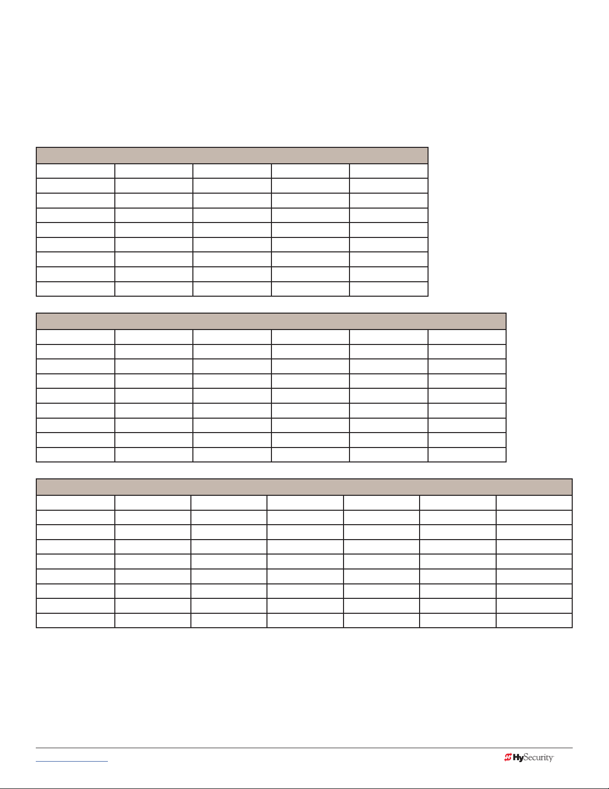
SlideDriver Wire Size Chart – 115V Single Phase
Horsepower ½ ¾ 1 2
Amps 10 11.6 14.4 27.2
Wire Gauge Distance Distance Distance Distance
12 90 (27m) 75 (23m) 60 (18m) 30 (9m)
10 140 (43m) 120 (37m) 100 (30m) 50 (15m)
8 220 (67m) 190 (58m) 155 (47m) 80 (24m)
6 350 (107m) 300 (91m) 245 (75m) 130 (40m)
4 555 (169m) 480 (146m) 385 (117m) 205 (62m)
2 890 (271m) 765 (233m) 620 (189m) 330 (101m)
SlideDriver Wire Size Chart – 208V Single Phase
Horsepower ½ ¾ 1 2 3
Amps 5.5 6.1 7.6 14.2 16.2
Wire Gauge Distance Distance Distance Distance Distance
12 290 (88m) 260 (79m) 205 (62m) 110 (33m) 100 (30m)
10 460 (140m) 415 (126m) 330 (101m) 175 (53m) 155 (47m)
8 725 (221m) 650 (198m) 525 (160m) 280 (85m) 245 (74m)
6 1150 (350m) 1040 (317m) 835 (254m) 445 (135m) 390 (119m)
4 1825 (556m) 1645 (501m) 1320 (402m) 710 (216m) 620 (189m)
2 2920 (890m) 2630 (801m) 2110 (643m) 1130 (344m) 1000 (305m)
SlideDriver Wire Size Chart – 230V Single Phase
Horsepower ½ ¾ 1 2 3 5
Amps 5.0 5.8 7.2 13.6 14.8 27.0
Wire Gauge Distance Distance Distance Distance Distance Distance
12 350 (107m) 300 (91m) 245 (75m) 130 (40m) 120 (37m) 65 (20m)
10 560 (171m) 480 (146m) 385 (117m) 205 (62m) 190 (58m) 105 (32m)
8 880 (268m) 760 (232m) 610 (186m) 325 (99m) 300 (91m) 165 (50m)
6 1400 (427m) 1120 (341m) 975 (297m) 515 (157m) 475 (145m) 260 (79m)
4 2220 (670m) 1915 (584m) 1550 (472m) 815 (248m) 750 (229m) 410 (125m)
2 3550 (1082m) 3080 (939m) 2465 (751m) 1305 (398m) 1200 (366m) 650 (198m)
www.hysecurity.com © 2017 Power MX3630-01 Rev. B 15
Page 26
NOTE: Distance shown in U.S. Standard “feet.” Metric equivalent shown in parentheses.
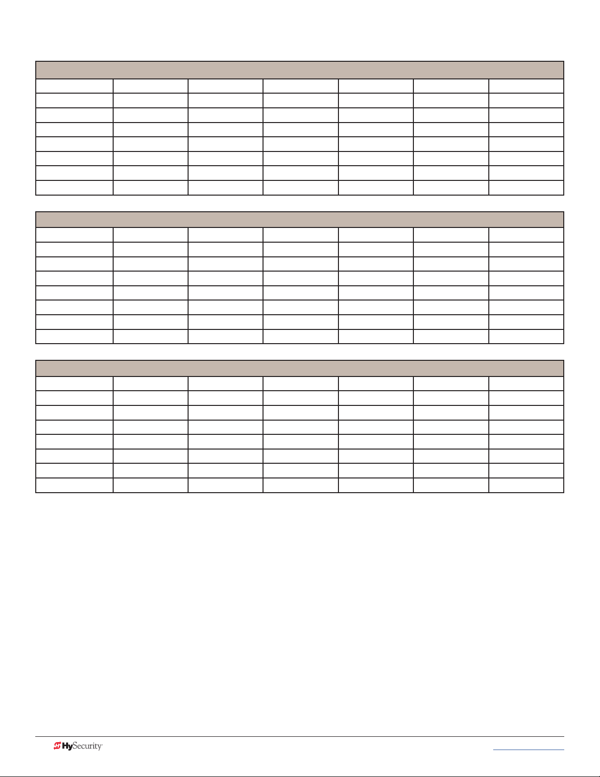
SlideDriver Wire Size Chart – 208V Three Phase
Horsepower ½ ¾ 1 2 3 5
Amps 2.7 3.1 4.2 6.5 6.7 16
Wire Gauge Distance Distance Distance Distance Distance Distance
12 590 (180m) 510 (155m) 375 (114m) 245 (75m) 235 (72m) 100 (30m)
10 930 (283m) 810 (247m) 600 (183m) 390 (119m) 575 (175m) 160 (49m)
8 1475 (449m) 1285 (392m) 950 (289m) 615 (187m) 595 (181m) 250 (76m)
6 2350 (716m) 2045 (623m) 1510 (460m) 975 (297m) 945 (288m) 400 (122m)
4 3720 (1134m) 3240 (987m) 2390 (728m) 1545 (471m) 1500 (457m) 630 (192m)
SlideDriver Wire Size Chart – 230V Three Phase
Horsepower ½ ¾ 1 2 3 5
Amps 2.4 3.0 3.8 6.2 6.4 15.4
Wire Gauge Distance Distance Distance Distance Distance Distance
12 730 (222m) 585 (178m) 460 (140m) 280 (85m) 270 (82m) 115 (35m)
10 1160 (353m) 930 (283m) 730 (222m) 450 (137m) 435 (133m) 180 (55m)
8 1835 (559m) 1470 (448m) 1160 (353m) 710 (216m) 690 (210m) 285 (87m)
6 2925 (891m) 2340 (713m) 1845 (562m) 1130 (344m) 1095 (334m) 455 (139m)
4 4625 (1410m) 3700 (1128m) 2920 (890m) 1790 (546m) 1735 (529m) 720 (219m)
SlideDriver Wire Size Chart – 460V Three Phase
Horsepower ½ ¾ 1 2 3 5
Amps 1.2 1.5 1.9 3.1 3.2 7.7
Wire Gauge Distance Distance Distance Distance Distance Distance
12 2915 (888m) 2350 (716m) 1850 (564m) 1130 (344m) 1100 (335m) 455 (139m)
10 4640 (1414m) 3710 (1131m) 2930 (893m) 1800 (549m) 1740 (530m) 725 (221m)
8 7340 (2237m) 5870 (1789m) 4650 (1417m) 2840 (866m) 2750 (838m) 1150 (350m)
6 11700 (3566m) 9350 (2850m) 7400 (2255m) 4550 (1387m) 4400 (1341m) 1800 (549m)
4 18500 (5639m) 14800 (4511m) 11700 (3566m) 7200 (2194m) 7000 (2134m) 2900 (884m)
16 MX3630-01 Rev. B SlideDriver/SlideDriver 50VF Series © 2017 www.hysecurity.com
Page 27
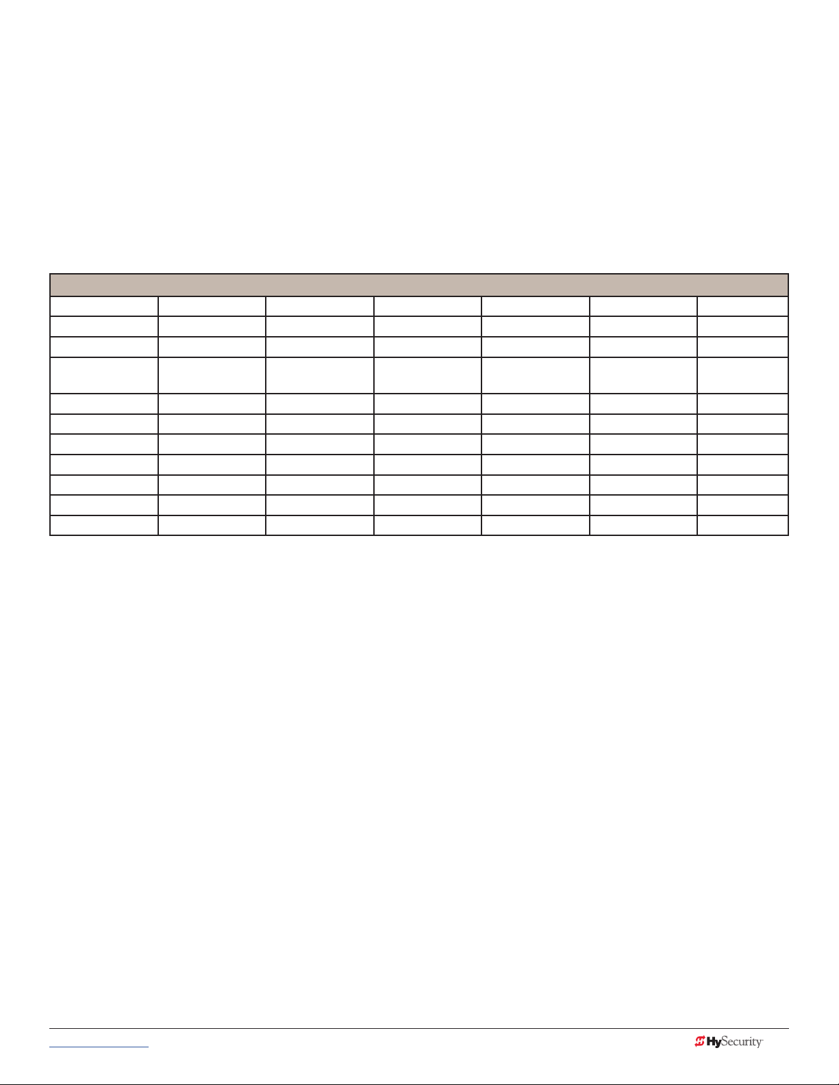
SlideDriver 50VF-series Wiring Chart (Incoming Power)
The maximum distance shown is from the operator to the power source, assuming that source power is from a
panel box with adequate capacity to support the addition of this motor load. The values are for one operator,
with no other loads applied to the branch circuit. Avoid placing more than one operator to a circuit, but if you
must, be certain to reduce the maximum allowed wire distance by half.
Make sure proper wiring is being used. The following table shows the maximum allowable wire run from the
power source to the operator for various wire sizes. Performance of 50VF-series operators on 1Ø and 3Ø
50 or 60 Hz Power.
NOTE: Distance shown in U.S. Standard “feet.” Metric equivalent shown in parentheses.
SlideDriver 50VF-series Wire Size Chart
Phase Ø 1 1 3 3 3 3
Voltage 208 230 208 230 380 460
Horsepower 2 2 2 2 2 2
VFD Rating
Amps
Wire Gauge Distance Distance Distance Distance Distance Distance
12 90 (27m) 100 (30m) 220 (67m) 240 (73m) 680 (207m) 830 (253m)
10 150 (46m) 170 (52m) 350 (107m) 390 (119m) 1090 (332m) 1310 (399m)
8 240 (73m) 270 (82m) 560 (171m) 620 (189m) 1730 (527m) 2100 (640m)
6 390 (119m) 430 (131m) 900 (274m) 990 (302m) 2750 (838m) 3330 (1015m)
4 620 (189m) 680 (207m) 1430 (436m) 1580 (482m) 4380 (1335m) 5300 (1615m)
2 990 (302m) 1090 (332m) 2280 (695m) 2530 (771m) 6990 (2130m) 8470 (2582m)
17.4 17.4 8.7 8.7 5.2 5.2
Performance of 50VF-series Operators on 1 and 3 Phase, 50 or 60Hz
A HySecurity 50VF-series operators can operate on a wide variety of incoming power.
• 50Hz/60Hz operation with no changes or reconnection
• 1Ø or 3Ø operation by eld rewiring and reconnection. The incoming voltage must match the operator
nameplate. Although the electric motor can be reconnected, a different VFD (motor controller inside
the grey control box) is required between 460V and 208V/230V.
• Any AC powered peripherals such as locks, card readers and other devices need to be checked for
compatibility.
www.hysecurity.com © 2017 Power MX3630-01 Rev. B 17
Page 28

How is this done?
WARNING
WARNING
• The VF controller in the operator is rated to operate on input frequencies ranging from 48Hz through
62Hz on 1Ø or 3Ø power (a jumper connection is required for phase change) but only on either
460VAC or 208V/230V. (A change between 460V and 230V, either direction, requires replacing the VF
controller).
• The control transformer in the operator is tapped for multiple voltages and rated for 50/60Hz
operation.
• The VF controller rst recties and lters the incoming power to DC, which has no frequency or phase.
It then creates 3Ø variable voltage/variable frequency AC for the motor from the DC.
• Depending on the model, the VF controller ramps the motor voltage and frequency from 0V@0Hz at
start, to either 208/230 or 460 VAC @ 60Hz for full speed. This allows use of 60Hz motors regardless of
the incoming frequency.
• Since the input voltage/frequency is converted to DC to begin with, there is absolutely no relationship
between the input frequency/phase and frequency/phase of the power supplied to the motor. The
input could be 1Ø or 3Ø, 48Hz or 62Hz and the controller/motor combination wouldn’t care. It will
create the ramped 3Ø voltage and frequency for which it is programmed.
NOTE: SlideDriver 50VF operators connected for 1Ø operation will draw more current because the utility power to run the machine
will be carried to the operator on two wires instead of the three used for 3Ø operators. Be sure to allow for this difference when
specifying wire size.
In-Field Connections
SlideDriver 50VF-series operators are eld re-connectable for 1Ø or 3Ø, 208/230VAC input power without
changing the VFD.
SlideDriver 50VF-series operators CANNOT be connected to 120V, 1Ø power or 575V, 3Ø power. If any attempts
are made to do so, serious injury, electrical shock, or death may result. Any electrical damage occurring to the
operator will not be covered by the Warranty.
SlideDriver 50VF-series operators are NOT eld recongurable between 208/230VAC and 460VAC power. The
VFD Motor Controller in a 208/230VAC unit must be replaced with a VFD Motor Controller manufactured for the
higher (460VAC) voltage input.
18 MX3630-01 Rev. B SlideDriver/SlideDriver 50VF Series © 2017 www.hysecurity.com
Page 29
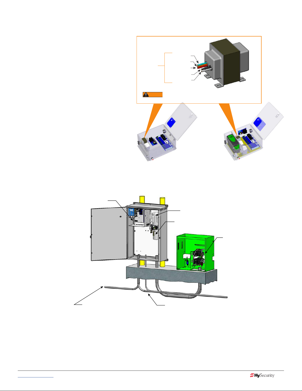
cOntrOL tranSfOrmer cOnnectiOnS (nOn-upS)
WARNING
Connect the AC input power to the control
transformer according to the following
procedure.
1. Ensure that the primary tap on the
control transformer matches the line
voltage and frequency connected to
the gate operator.
Input taps
Blue - 460 VAC
Orange - 240 VAC
Red - 208 VAC
Black - Common
White - 120 VAC*
2. Measure the line voltage carefully to
distinguish between 208V and 230V
branch circuits.
NOTE: A label on the transformer top
identies the various voltage taps available.
* Variable Frequency (VF) or 2 hp gate operators:
connection wires match the voltage found on the operator’s nameplate.
Never connect to the white 120V wire. Make sure the
Control Transformer
3. Use wire nuts or crimp-connectors to
connect the power input conductors
to the applicable taps on the Control
Transformer.
All (Excluding SD50VF) SD50VF - series
Gate OperatOr cOnnectiOnS (mOduLar unit)
Control box with display
Electric motor
Hydraulic pump pack
Hydraulic motors,
Drive wheels,
Limit switches,
Toggle handle release
High voltage electrical
power input wiring
Vehicle detector & control
signal input wiring
If you have the modular unit, additional conduit is needed to house the hydraulic hoses and electrical wiring.
You need a 2-inch (5 cm) diameter conduit for hydraulic hoses and a ¾-inch (19 mm) conduit for electrical
wiring. AC input power is connected to the hydraulic pump and electrical components enclosure
(HydraSupply).
A supplemental manual, provided with the product, describes the installation overview, wiring and conduit
considerations.
www.hysecurity.com © 2017 Power MX3630-01 Rev. B 19
Page 30

dc pOWer SuppLy (upS) cOnnectiOnS
If you have a gate operator with a DC Power Supply unit, you will need to
connect the primary AC input power to the DC Power Supply.
Additional ¾-inch (19 mm) conduit is needed for electrical wiring
interconnections between the gate operator and DC Power Supply
Cabinet. AC input power is connected to the electrical components in
the chassis, and additional wiring is run through conduit to the DC Power
Supply Cabinet.
System features are covered in the DC Power Supply Installation
Posts
Conduit
Instructions supplement shipped with the product and available online at
www.hysecurity.com.
ac pOWer SuppLy WitH Hyinverter ac
Gate operators equipped with the AC Power Supply with HyInverter AC option are powered by four 12-Volt,
110Ah DC batteries which, when AC power loss occurs, maintain a true Uninterrupted Power Supply (UPS)
system. When the local AC power fails, the UPS back up system continues to move the gate. System features
are covered in the HyInverterAC Installation and Reference Manual shipped with the product and available
online at www.hysecurity.com.
NOTICE: The AC Power Supply with HyInverter AC option is intended for single phase (1 hp) gate operators and
single phase (2 hp) gate operators that use Variable Speed Drives (VFD).
Straps
Footman
Loops (2x)
HyInverter AC
Four 12V, 110Ah AGM batteries
Internal & external wiring not shown.
Drawing is not to scale
20 MX3630-01 Rev. B SlideDriver/SlideDriver 50VF Series © 2017 www.hysecurity.com
Page 31

Initial Setup
CAUTION
When you rst apply power to the operator, it is locked in Menu mode
and prompts appear on the display. The gate will not move and the controls
will not function until the prompts have been answered. The prompts
include:
• Usage Class setting
• Gate handing
• Three external entrapment protection SENSOR assignments
Before turning the power switch to ON, be sure to replace the vent cap with the
breather cap. See page 23. Make sure all site requirements concerning proper
wiring, safety, foundation installation, and electrical power have been met.
Five buttons on the display keypad provide operational controls. Refer to
Display & Menu Options on page 41 for more information. To answer the
initial prompts, use the Previous, Next, and Select buttons as described in
the chart below:
UC 2
USAGE CLASS
Smart Touch Controller: Menu Mode Navigation Buttons
To change that data
appearing in the display
Press Select.
Two left characters blink.
To navigate through the
Selections
Press Next.
Continue pressing Next to view
all selections. (Press Previous to
reverse direction.)
To choose what appears on
the display
Press Select.
Blinking characters
become static.
To navigate between
menu items
Press Next or Previous.
Advance - press Next
Previous - press Previous
If you are unsure of the usage classication, refer to Identifying Gate Operator Category and Usage Class on
page 5. It explains the different usage site classications for UL 325.
Gate HandinG
The handing is determined by the position of the operator and which way the gate opens. To determine
handing, face the front cover panel on the operator. All SlideDrivers are set at the factory for right handing. If
the gate has left handing, the hydraulic hoses must be swapped. See page 22.
OPEN OPEN
Left-Hand
Gate
www.hysecurity.com © 2017 Initial Setup MX3630-01 Rev. B 21
Right-Hand
Gate
Page 32

HydrauLic HOSe SWap
SH L
GATE HANDING
Gate Handing is determined by viewing the gate opening from the secure side. See illustration on page 21.
If the gate opens to the left, the gate must be set for left handing.
All SlideDrivers are set at the factory for right handing. If the gate has left handing, you must
• Select SH L when prompted (SH is an
• Swap position of the hydraulic hoses.
Installer Menu item.)
Factory set for right-handing.
Swap hose connections for
left-handing gate.
adjuStinG tHe Brake vaLveS
Proper adjustment of the brake valves is important for smooth operation
of the gate. The position and placement of the limit ramps on the drive rail
plays an important part on how the brake valves work.
Brake valves
In order for the brake valves to have time to function, the limit ramp must
trigger the limit switch at least two inches before end of gate travel.
Adjustment of the brake valves, one for each direction of travel, will
determine how quickly the gate actually stops.
The adjustment is counter-intuitive.
A counter-clockwise adjustment stops the gate more rapidly. If the
adjustment is set too loose, the limit ramps will bang into the drive wheels.
If the adjustment is set too tight, the system pressure will increase, the gate
speed may decrease and the gate will jerk to a stop.
Brake valves are factory-set to midpoint, two turns. This should be sufcient for most applications.
1. If the limit switch triggers and the drive rail stops more than two inches into the limit ramp, increase
braking. If adjustment is needed, loosen the >\zn-inch lock nut on the top of the brake valve and make
¼-inch incremental turns on the adjustment stem with a hex key. Note that the adjustment screw varies
depending on model type.
2. When the adjustment is complete, retighten the locking nut to hold the setting.
22 MX3630-01 Rev. B SlideDriver/SlideDriver 50VF Series © 2017 www.hysecurity.com
Page 33

GrOundinG, BreatHer cap inStaLLatiOn & HandinG
DANGER
The gate operator has a vent plug that keeps the hydraulic uid from spilling during shipment. The vent plug
must be replaced by the breather cap before operating the slide gate.
Failure to perform the following procedure will cause premature pump shaft failure and void the Warranty.
1. Remove the vent plug and discard it.
2. Replace the vent plug with the breather cap.
SlideDriver
Replace red vent plug
with breather cap
3 ft
(91.4 cm)
Maximum
distance
Operator is shipped
hydraulically congured for
“right hand” operation. Refer
to Gate Handing on page 21.
Factory set for right-handing.
Swap hose connections for lefthanding gate.
Grade level
Cut-away view
Concrete foundation
Consult local
codes for
proper depth
Ground rod
www.hysecurity.com © 2017 Initial Setup MX3630-01 Rev. B 23
Page 34

SLidedriver SLOW dOWn Limit rampS
CAUTION
Drive rail
Round-head bolts:
3/8 " (9 mm)
Must be fully
tightened and ush
before adjusting
limit switch.
4"
10 cm)
Support
Post
4" (10 cm)
Spacing approximate
Limit
Switch
Base of Drive
Rail
3/8 " (9 mm)
Height
Adjusting
Screw
2"
(5 cm)
Nut
Standard Limit Ramp
The standard limit ramp is positioned
on the drive rail so it will make
contact with the limit switch and stop
approximately 2 inches (5 cm) from the
drive wheel.
Limit ramps are attached to the
underside of the drive rail when the
gate is fully open and fully closed.
U-bolt
Roller
Chassis
cutout
Limit Ramp
Limit Ramp
Limit Ramp
enters chassis
cutout
Actuating Arm
(Tripped position)
Drive
Wheel
2" (5 cm)
Two truss head screws secure each limit ramp to the drive rail. The
bolts are spaced about 4 inches (10 cm) apart.
The limit switch must be set ⅜-inch (9 mm) from the base of the
drive rail. A screw on the limit switch allows for slight adjustments
in height. If XtremeDrive wheels are used, you will need to raise the
drive rail ¼ to ½ inch (3 to 13 mm) along the gate uprights and the
entire drive rail path. The limit switch placement will need to be
adjusted accordingly.
All the limit ramps are the same length.
NOTE: For a 50VF-series SlideDriver, you will need to order four (4) Slow Down
Limit Ramp Kits.
Nut
Be sure to securely fasten all limit ramps to the underside of
SlideDriver 50VF
the drive rail when installing a 50VF-series operator.
Slow Down Limit Ramp Kit
24 MX3630-01 Rev. B SlideDriver/SlideDriver 50VF Series © 2017 www.hysecurity.com
Page 35

adjuStinG tHe preSSure reLief vaLve
CAUTION
When placing the operator into service, pressure relief valve
adjustments are required! To provide instruction during
installation, a cautionary yellow tag is wire tied to every pump
pack. The same instructions are provided in this section.
Pressure relief valves differ depending on the model.
Tools Needed: 5/3 2 " hex key, ½" and 9/1 6 " box end wrenches.
NOTICE: Pressure relief valve adjustments establish the threshold for the inherent entrapment sensor (IES). The
optimal pressure setting produces uniform gate travel and trips the IES when the gate encounters an obstruction.
Model Motor hp Maximum PSI
SlideDriver 15, 40 1 hp 1000 psi
SlideDriver 30F, 80, 50VF 2 hp 1350 psi
SlideDriver 200 5 hp 2000 psi
Never exceed the maximum psi setting.
Hex socket adjustment screw
SlideDriver 30F, 80, 200
Pressure
Gauge
The Pressure Relief
Valve is located
behind the motor
on the pump rack or
soft start manifold.
Motor
Pump
pack
Hex head adjustment screw
SlideDriver 15, 40, 50VF
www.hysecurity.com © 2017 Initial Setup MX3630-01 Rev. B 25
Page 36

Make sure the gate is properly installed and aligned before performing the following steps. Take precautionary
DANGER
SP 2
SPEED
measures to keep the gate’s travel path clear. The gate will be moving while you adjust the pressure relief
valve.
DO NOT attempt to adjust the pressure relief valve unless you are an experienced hydraulic gate
operator installer. Incorrect pressure settings can cause injury and even death!
1. Expose several threads on the Pressure Relief Valve by loosening the locknut with a 9/1 6 " box end wrench.
2. Depending on the model, insert a 5/3 2" hex key or use a ½" box end wrench to turn the Adjustment
Screw.
3. Use the keypad to cycle the gate open or close and, while the motor is running, turn the Adjustment
Screw clockwise (CW) to raise the pressure. The motor runs for a few seconds, stops, and then enters
safe mode. SAFE appears on the display.
4. Press RESET and repeat step 3 until gate travel is reliably consistent without entering SAFE mode.
5. To lock in the pressure setting, hold the Adjustment Screw with a hex key or wrench and tighten the
locknut.
mOdBuS rtu in SLidedriver 50vf-SerieS
In the 50VF series SlideDriver™, a communication protocol allows the Smart Touch
Controller to constantly monitor the Variable Frequency Drive (VFD) and record
events in the STC history log. The history log is easily accessible using the HySecurity
S.T.A.R.T. program and a PC laptop computer or view history log codes by accessing
the User Menu, LG item (software version h5.53 or higher).
With the ModBus RTU:
• Reduction in eld calls is likely because the STC resets VFD faults or error
codes upon receiving a new command.
• Quality issues with the site power are controlled better which results in less
intermittent operator problems.
• Smoother operator acceleration and deceleration enhances gate travel.
All 50VF2-3 series SlideDrivers shipped after January 1, 2012 have the new ModBus cable and RTU
communication protocol installed. If you need replacement parts for your existing 50VF series operators,
be sure to have the serial number of the
operator available when you order parts.
If you install a new 50VF2/3 operator, the speed is factory set at 2 foot per
second (2 ft/s). To change the speed, you will need to access the Installer
Menu.
• SP 2 sets the 50VF2/3 speed to approximately 2 ft/s.
• SP 3 sets the 50VF2/3 speed to approximately 3 ft/s.
Refer to Emergency Fast Operate (EFO) in SlideDriver 50VF-series on
page 27.
• SP 0 and SP 1 are not used. (If you change the setting to 0 or 1, the
operator will not run.)
26 MX3630-01 Rev. B SlideDriver/SlideDriver 50VF Series © 2017 www.hysecurity.com
Page 37

emerGency faSt Operate (efO) in
SLidedriver 50vf-SerieS
To enable the Emergency Fast Operate option on a SlideDriver 50VF-series operator, you need to program the
Smart Touch Controller by taking the following steps:
NOTE: When you are in programming mode the buttons on the keypad change from Open, Close, and
Stop to Previous, Next, and Select. Refer to Menu Mode Navigation on page 42.
1. Make sure the operator is turned ON and a Run mode status (example,
GATE OPEN) appears on the Smart Touch Controller, which indicates the
machine is operational.
2. Press the Menu button twice to access the User Menu.
3. Press and hold the Reset button and then the Open button. Hold the
buttons for two seconds and then release both buttons.
4. Press Next until the Emergency Close (OC 0)appears on the display.
5. Press Select and OC starts blinking, which indicates the display can be
changed.
6. Press Next or Previous to change the display to OC 1.
7. Press Select to accept the entry. (The display characters stop blinking.)
HYSECURITY
GATE OPEN
OC 1
EMERGENCY CLOSE
8. Press Menu to exit programming mode and return to Run mode.
A Run mode gate status appears (example, GATE OPEN).
www.hysecurity.com © 2017 Initial Setup MX3630-01 Rev. B 27
Page 38

inStaLLinG a puSH ButtOn device
VEHICLE DETECTORVEHICLE DETECTORVEHICLE DETECTOR
VEHICLE DETECTOR
fOr emerGency faSt Operate (efO)
The Emergency Fast Close on the 50VF-series is designed for a
constant hold function, such as a push-button device that is
held for the duration of gate travel. To operate properly, the
device must be connected to Terminal 23 on the Smart Touch
Controller and a +24VDC terminal on the Power Supply Board.
When the connections are made, the constant hold signal
transmitted to the Smart Touch Controller activates the close
function. The gate closes at a higher speed than usual. Photo
eyes, vehicle loop inputs, and other safety devices (such as
external entrapment protection sensors) are ignored.
Emergency Fast Close Speeds
Operator Close Speed EFO Close
SlideDriver 50VF2 2.2 fps (26 in per sec) 3 fps (91 cm/s)
SlideDriver 50VF3 3 fps (91 cm/s) 3 fps (91 cm/s)
24V
A
C A
Emergency Fast
Close Device
(Actuator)
Power Supply Board
cce
s
s
or
y powe
r
Power Connector
USER 3
HySecurity
MX000585
VERSION
S/N
RADIO OPTIONS
RS485
STOP/BUZZER
MOTOR USER 1
FREE
EXIT
USER 2
INSIDE
OBSTR
OUTSIDE
OBSTR
COM
NO
STATUS
SHADOW
RESET
DISPLAY
RS232
WIEGAND
COMOPEN S1+24V +24V
STOP BUTTON
OPEN BUTTON
CLOSE BUTTON
REMOTE OPEN AND
RADIO CONTROL
OPEN/CLOSE
OPEN PARTIAL
INTERLOCK OPEN
TIME CLOCK OPEN
FREE EXIT DETECTOR
DISABLE EXIT DETECTOR
DISABLE CLOSE TIMER
INSIDE OBSTRUCTION
VEHICLE DETECTOR
OUTSIDE OBSTRUCTION
VEHICLE DETECTOR
SHADOW/RESET
VEHICLE DETECTOR
SENSOR 1
SENSOR COM
SENSOR COM
DO NOT USE
SENSOR 2
DO NOT USE
SENSOR 3
DO NOT USE
CHARGER
AC LOSS
LOCK INTERLOCK
EMERG CLOSE
FIRE DEPT OPEN
Smart Touch Controller
RPM
COM COMA B
POWER
DRIVE
1
2
3
4
5
6
7
8
9
10
11
12
14
15
16
17
18
19
20
21
22
23
24
LED
LIMIT DUAL GATE
C
D
V
24
+
ON
MM
O
C
28 MX3630-01 Rev. B SlideDriver/SlideDriver 50VF Series © 2017 www.hysecurity.com
Page 39

Entrapment Protection
Effective January 12th, 2016 UL 325 Standard of Safety requires all automated gate operators be able to
monitor for entrapment protection sensors. Before gate movement occurs, the UL 325 compliant HySecurity
gate operator veries that the external entrapment protection sensors are connected and fully functional.
The site designer or installer must determine which external entrapment protection sensors will be installed
with the gate operator to create a UL 325 compliant installation site.
The following bullet points highlight how your automated gate system sites can monitor sensors (external
entrapment protection sensors) using HySecurity gate operators:
• Normally Closed (NC) sensors - Installing Normally Closed output sensors. External entrapment
protection NC sensors are “monitored” by HySecurity gate operator software.
• Build Year (BY) - An added menu item distinguishes between pre-2016 manufacturing dates and
UL 325 - 2016 manufacturing dates. Build Year (BY) is a factory-setting. Build Year 2 (BY 2) is the
default for all HySecurity gate operators indicating a manufacturing date of 2016 in the serial number.
Replacement controller boards for existing sites allow for a Build Year setting of 1 (BY 1, pre-2016).
• Independent Sensor Inputs - The edge, photo eye and photo eye COM inputs on the Smart Touch
Controller (STC) have been re-labeled. The same wiring connections become three independent
methods for easy entrapment sensor conguration and normally closed outputs. Refer to the tables in
the front of this manual.
NOTICE: To enable fully automatic operation, the gate operator requires a MINIMUM of one external entrapment
protection sensor to monitor potential entrapment zones in either the open or close direction of travel.
Visit www.hysecurity.com/gatesafety for more information on UL 325 standards and gate safety.
manufacturer’S reSpOnSiBiLity
• Build into the gate operator a means of detecting an obstruction or an inherent entrapment detection
sensor
• Monitor input from external entrapment detection sensors
• Provide warning signs and an installation manual which, if followed, will result in a UL 325 compliant
installation
Pressure Relief Valve – All Hydraulic Operators:
• Limits hydraulic system pressure
• Bypasses uid to tank when set-point exceeded
• Bypassed uid triggers the IES
NOTICE: Pressure relief valve adjustments establish the threshold for the Inherent Entrapment Sensor (IES). The
optimal pressure setting produces uniform gate travel and trips the IES when the gate encounters an obstruction.
www.hysecurity.com © 2017 Entrapment Protection MX3630-01 Rev. B 29
Page 40

Inherent Entrapment Sensor System – Hydraulic Operators (IES)
The IES sensor:
• Is a normally closed pressure switch on the pump manifold
• Senses uid ow. High pressure spikes above pressure relief valve setting trigger gate obstruction
notication
• Ignores rst second of operation to preclude false trips due to starting pressure spike
An open contact:
• During gate movement signals the Smart Touch Controller to place gate operator into SAFE mode
• While the gate is not operating will generate ERROR 2 (ERR2) - disconnected IES
NOTE: A second open contact, in either direction of travel, will lock the gate operator and ENTRAPMENT
MODE (ENTR) appears on the display.
tHe inHerent entrapment SenSOr (ieS)
The IES on HySecurity gate operators is an entrapment sensor that is required by UL 325 as a Type “A”
detection sensor. It is tripped through software programming OR hydraulic pressure settings. It does not
function solely on its own accord and must be connected to the Smart Touch Controller. The sensitivity and
response of the IES when tripped is factory set, but can be adjusted through the Installer Menu items:
• SE (Inherent Sensor sensitivity)
• SS (Inherent Sensor function)
• SR (IES reverse to open)
Smart Touch Controller™ – Installer Menu Functions for IES
Installer Menu
Display Code
SE 2
IES SENSITIVITY
SS 0 (OFF)
IES STOP ONLY
SR 0 (FULL OPEN)
REVERSAL LOGIC
1 = max. sensitivity
2 = Default setting
9 = least sensitivity
0 = stop, reverse for 2s
1 = stop only
0 = IES reverses full open
1 = 2 second reversal only
Setting Options
(Bold – Factory Settings)
Description
Adjusts the sensitivity of the internal inherent entrapment sensor
(IES). Available settings are 1 to 9 with 9 being the least sensitive.
HySecurity strongly recommends that you avoid setting the IES
sensitivity higher than 6.
Note: Adjust pressure relief valve on hydraulic operators for security
and gate impact purposes prior to changing IES sensitivity. Refer to
the operator’s manual for steps involved in adjusting the pressure
relief valve setting.
A setting of 0, stops the gate and then reverses its direction of travel
for 2 seconds. To stop gate travel with no reversal, the optional
setting 1 can be selected if the gate operator is at a Usage Class IV
site and assigned a UC 4 classication.
The default setting is a 2-second duration reversal if the inherent
sensor is triggered. The optional setting of 0 will cause the gate to
reopen fully if triggered while closing.
30 MX3630-01 Rev. B SlideDriver/SlideDriver 50VF Series © 2017 www.hysecurity.com
Page 41

HOW SOftWare HandLeS mOnitOrinG externaL
entrapment prOtectiOn SenSOrS
HySecurity gate operators use software to control gate movement, contacts, and accessories. The changeover
in 2016 to monitoring sensors has been a simple process.
• Build Year is a new Installer Menu item in the Smart Touch Controllers versions h4.50 (and higher).
• New labels show where Edge, Photo Eye Open and Photo Eye Closed have changed to “SENSOR”
inputs. You can program the type of sensor wired to one of those inputs. See table below.
• Installer Menu items, PC and GC (Photo eye output and edge sensor output) which used to default
to Normally Open (NO) have been converted to Normally Closed (NC) contacts so the software can
detect the presence and proper operation of external entrapment protection sensors.
Table 4: Changes to Sensor Inputs on the Controller
Location of Sensor Inputs on Controller Installer Menu Item Codes
Smart Touch Controller (STC): Hydraulic gate operators Smart Touch Display:
Input # Current Silk Screen Label 2016 Silk Screen
Label
13 EDGE SENSOR SENSOR 1 S1 SENSOR 1
17 PHOTO EYE OPEN DIRECTION SENSOR 2 S2 SENSOR 2
19 PHOTO EYE CLOSE DIRECTION SENSOR 3 S3 SENSOR 3
OLED - two line,
32 character
LCD - 7
segment text
S1
S2
S3
NOTE: Three inputs for external entrapment protection sensors are available on the HySecurity gate operator controller. New
silk screen controller boards are on order, but until they are ready for shipment, labels will be overlaid on the board to indicate
terminology adaptations.
Table 4 indicates how the edge and photo eye inputs have been renamed to generic “sensor” inputs. They are
interchangeable and congurable. The software must know what type of sensor is wired to SENSOR 1, 2, and 3
BEFORE it will allow gate travel.
externaL entrapment prOtectiOn SenSOrS:
WHat tHe inStaLLer needS tO dO
NOTE: All HySecurity gate operators, indicating a manufacturing date of 2016 in the serial number, will have the Build Year set to 2.
A Build Year of 2 (BY 2) indicates that your gate operator is prepared to monitor for external entrapment protection sensors.
The Build Year setting appears in the system scroll on the gate operator display. The gate operator will not automatically cycle
the gate unless an indication that the appropriate number of external entrapment protection sensors are connected and
operational.
The normally closed (NC) entrapment protection sensors wired to the Controller’s SENSOR inputs are
monitored using HySecurity software. Prompts appear in the display requesting specic congurations based
on the gate operator type.
Table 5: Installer Menu Settings for SENSOR Inputs illustrates what options are available for the HySecurity
Controller’s congurable inputs. What used to be inputs labeled: Edge, Photo Eye Open, Photo Eye Close,
and Edge COM now become:
SENSOR 1 SENSOR 2 SENSOR 3 SENSOR COM
www.hysecurity.com © 2017 Entrapment Protection MX3630-01 Rev. B 31
Page 42

1
2
CAUTION
All external entrapment protection sensors must be wired to the SENSOR COM terminal for power and
monitoring purposes. The three SENSOR inputs are interchangeable and congurable. For example, it doesn’t
matter whether you wire a normally closed photo eye sensor or edge sensor to the SENSOR 1, 2, or 3 input.
However, due to monitoring requirements, each SENSOR input (1, 2, and 3) can only accept one NC sensor
output connection.
Assess Your Gate Site.
Design your gate installation so entrapment zones are kept to a minimum, and then install
your HySecurity gate operator.
NOTICE: UL 325 Standard of Safety provides the MINIMUM safety standards. Site, gate hardware usage, and other
conditions may dictate the use of additional safety designs/components. It is up to the gate system designer and
installer to assess appropriate safety design and components above and beyond minimum UL 325 and ASTM F2200
standards. Always check your local area codes and comply with all regulations.
Draw-in zone
Edge sensor (protecting open direction)
(EDGE OPEN)
Photo eye thru beam protecting
Leading End
(EYE CLOSE)
Photo eye thru-beam
protecting Trailing End
(EYE OPEN)
Install NC sensors.
Install contact and non-contact sensors (edge sensors and photo
eyes) for all entrapment zones. HySecurity gates monitor normally
closed (NC) sensors. Wire your NC sensors to SENSOR input terminals
(SENSOR 1, SENSOR 2, or SENSOR 3) on the Smart Touch Controllers.
NOTE: When installing wired edge sensors, the wired edge must be connected to an interface module with an NC
output. See Wiring HySecurity Sensors: Smart Touch on page 109. For wireless edge sensors, no interface module is
required. Wireless edge sensors need the wireless gate links which include a transmitter and receiver.
32 MX3630-01 Rev. B SlideDriver/SlideDriver 50VF Series © 2017 www.hysecurity.com
Page 43

3
Turn Power ON.
4
Hydraulic
I/0 Switch
SlideDriver Control Box
NOTE: On the next page, review
LED function and how to provide
temporary power to the sensors.
2
4
V
A
C
A
c
ce
COMM
ss
o
ry
p
ower
S1 2 (EYE CLOSE)
SENSOR #1 TYPE
DRIVE
1
2
3
4
5
6
7
8
C
D
V
4
2
+
ON
9
10
11
12
14
15
16
17
18
19
20
21
22
23
24
LIMIT DUAL GATE
STOP BUTTON
OPEN BUTTON
CLOSE BUTTON
REMOTE OPEN AND
RADIO CONTROL
OPEN/CLOSE
OPEN PARTIAL
INTERLOCK OPEN
TIME CLOCK OPEN
FREE EXIT DETECTOR
DISABLE EXIT DETECTOR
DISABLE CLOSE TIMER
INSIDE OBSTRUCTION
VEHICLE DETECTOR
OUTSIDE OBSTRUCTION
VEHICLE DETECTOR
SHADOW/RESET
VEHICLE DETECTOR
SENSOR 1
SENSOR COM
DO NOT USE
SENSOR 2
DO NOT USE
SENSOR 3
DO NOT USE
CHARGER
AC LOSS
LOCK INTERLOCK
EMERG CLOSE
FIRE DEPT OPEN
LED
Smart Touch Controller
RPM
COM COMA B
POWER
USER 3
HySecurity
MX000585
VERSION
S/N
RADIO OPTIONS
+24V +24V
Answer Initial Setup Prompts.
For slide gates you will be prompted for USAGE CLASS,
GATE HANDING, and SENSOR 1, SENSOR 2, and
SENSOR 3. Each SENSOR input, whether or not it has a contact or non-contact sensor wired to it, must be
programmed to a non-zero setting before the gate will move.
RS485
STOP/BUZZER
MOTOR USER 1
FREE
EXIT
USER 2
INSIDE
OBSTR
OUTSIDE
OBSTR
COM
NO
VEHICLE DETECTORVEHICLE DETECTORVEHICLE DETECTOR
STATUS
SHADOW
RESET
DISPLAY
VEHICLE DETECTOR
RS232
WIEGAND
COMOPEN
S 1
NOTE: The gate operator will not automatically cycle unless an indication is received that the appropriate number of external
entrapment protection sensors are connected and operational. At minimum, external entrapment protection sensors must be used
to protect both open and close directions of gate travel.
Smart Touch and Smart DC Controller: Menu Mode Navigation Buttons
To change data
appearing in the display
Press Select.
Two left characters blink.
To navigate through
the Selections
Press Next or Previous.
Continue pressing Next to view
all selections.
To choose what appears
on the display
Press Select.
Blinking characters
become static.
To navigate between
menu items
Press Next or Previous.
Advance - press Next
Previous - press Previous
Table 5: Installer Menu Settings for SENSOR Inputs
UL 325
HySecurity Gate
Operator
SlideDriver
(xed speed)
SlideDriver VFD 2
SlideSmart DC 15 2
SlideSmart DC 10 2
SwingRiser 2
SwingSmart DC 2
HydraSwing 2
HydraLift 2
Build
Year
2016
(BY set)
2
Installer Menu Settings for STC & SDC Sensors 1, 2, or 3 (solo operators)
#0
DISABLED
#1
NOT USED
#2
EYE CLOSE
#3
EDGE
CLOSE
#4
EYE OPEN
#5
EDGE
OPEN
#6
EDGE BOTH
DIRECTIONS
● ● ● ● ● ● ●
● ● ● ● ● ● ●
● ● ● ● ● ● ●
● ● ● ● ● ● ●
● ● ● ● ● ● ●
● ● ● ● ● ● ●
● ● ● ● ● ● ●
● ● ●
#7
EYE BOTH
DIRECTIONS
NOTE: HySecurity does not update software for SlideWinder models. For information regarding HySecurity gate operators not
shown in the table above, refer to Table 2: HySecurity Gate Operators maintaining Object Detection on page ii.
www.hysecurity.com © 2017 Entrapment Protection MX3630-01 Rev. B 33
Page 44

SuppLy pOWer tO tHe SenSOrS
CAUTION
All external entrapment protection sensors must be wired to the SENSOR COM terminal for monitoring purposes.
Review sensor wiring diagrams found in Wiring HySecurity Sensors: Smart Touch on page 109.
Until the gate operator receives a command to run (open or close command), the sensors are not receiving
power. However, to temporarily power sensors and check that the gate operator is monitoring the sensors
properly, turn on Photo Eye Align mode.
To turn on Photo Eye Align mode, take the following steps:
1. Access the User Menu and select PE. (Press the Menu button twice to access
the User Menu. See Menu Mode Navigation Buttons chart on the previous
page.)
2. Press NEXT and continue to press NEXT until PE 0 (OFF) appears.
3. Press SELECT.
PE characters begin blinking.
4. To turn ON photo eye alignment and temporarily power the sensors, press
NEXT so PE 1 (ON) appears.
PE 1 (ON)
PHOTO EYE ALIGN
5. Press SELECT.
PE stops blinking.
6. Press MENU to exit Menu Mode and return to Run Mode.
NOTE: The Photo Eye Align mode turns OFF with the next limit contact. For more information, see Photo Eye
Alignment Feature on page 86.
Controller Temporarily apply Power to Sensors LED Status
Smart Touch
(Hydraulic gate
operators)
Smart DC
(electro-mechanical
gate operators)
PE 1 (ON)
PHOTO EYE ALIGN
PE 1 (ON)
PHOTO EYE ALIGN
PE 1 (ON)
PHOTO EYE ALIGN
OPEN
PREV
CLOSE
NEXT
STOP
SELECT
MENU
LEDs next to the sensor connections will be lit when no power
is being applied. When PE is turned ON, the LEDs turn off. If
they do not turn off, check for wiring issues such as a short or
misapplied relay COM connections. See CAUTION on page 32.
When PE is ON, the LEDs associated with the sensor devices
will be lit if the sensors are properly connected and sensors
are grounded. The LEDs turn off when the ground circuit is
removed.
RESET
34 MX3630-01 Rev. B SlideDriver/SlideDriver 50VF Series © 2017 www.hysecurity.com
Page 45

Control Panel Overview
This section provides an overview of the electrical controls found in your gate operator. The illustrations
highlight the various components and describe their function. Each callout explains where to nd more
information about the component.
SlideDriver Models: All, except 50VF-series
Transformer:
Provides the connections for AC power and steps
down the voltage to 24VAC. For more information,
refer to Control Transformer Connections (Non-UPS)
on page 19.
Power Supply Board
Provides common and 24VAC & 24VDC terminals.
Refer to Overview of the STC and Power Supply
Board on page 58.
Control Box
Reset Switch
Power Switch
www.hysecurity.com © 2017 Control Panel Overview MX3630-01 Rev. B 35
Smart Touch Controller:
Provides inputs for peripherals and accessories, 2
electromechnical user relays (250VAC, 10A), one solid
state user relay (30VDC, 3A). For more information, refer
to STC Terminal Inputs on page 60.
Page 46

SLidedriver WirinG diaGram, d0266 rev B
BLUE 480
ORANGE 240
RED 208
WHITE 120
3 PHASE
ONLY
DRIVE
STOP BUTTON
1
2
OPEN BUTTON
3
CLOSE BUTTON
REMOTE OPEN AND
4
RADIO CONTROL
5
OPEN/CLOSE
OPEN PARTIAL
6
INTERLOCK OPEN
7
TIME CLOCK OPEN
FREE EXIT DETECTOR
8
DISABLE EXIT DETECTOR
9
DISABLE CLOSE TIMER
INSIDE OBSTRUCTION
10
VEHICLE DETECTOR
OUTSIDE OBSTRUCTION
11
VEHICLE DETECTOR
SHADOW/RESET
12
VEHICLE DETECTOR
SENSOR 1
14
SENSOR COM
15
DO NOT USE
16
SENSOR 2
17
DO NOT USE
18
19
SENSOR 3
20
DO NOT USE
CHARGER
21
AC LOSS
LOCK INTERLOCK
22
EMERG CLOSE
23
FIRE DEPT OPEN
24
LED
LIMIT DUAL GATE
RPM
COM COMA B
POWER
USER 3
HySecurity
MX000585
VERSION
S/N
Smart Touch Controller
RADIO OPTIONS
+24V +24V
S 1
RS485
DISPLAY
EXTERIOR
STOP/BUZZER
RESET
MOTOR USER 1
FREE
EXIT
USER 2
INSIDE
OBSTR
OUTSIDE
OBSTR
COM
NO
VEHICLE DETECTORVEHICLE DETECTORVEHICLE DETECTOR
STATUS
SHADOW
RESET
VEHICLE DETECTOR
RS232
WIEGAND
COMOPEN
DUAL GATE
HYSECURITY
GATE STOPPED
36 MX3630-01 Rev. B SlideDriver/SlideDriver 50VF Series © 2017 www.hysecurity.com
Page 47

variaBLe Speed drive (vfd) cOntrOL BOx
SlideDriver 50VF Models
Variable Frequency Drive
(VFD): Controls RPM for smooth
acceleration & deceleration and
connects to the STC through
ModBus communication wires
for diagnostic purposes and
control handling.
CAUTION
Residual voltage remains in the
VFD which can cause electrical
shock to personnel or damage
to the equipment.
Transformer:
Provides the connections for AC
power and steps down the voltage to
24 VAC. For more information, refer
to Control Transformer Connections
(Non-UPS) on page 19.
CAUTION
* On VFD operators, never connect
to the white 120V wire. Make sure the
connection wires match the voltage
label found on the operator’s name
plate.
www.hysecurity.com © 2017 Control Panel Overview MX3630-01 Rev. B 37
Page 48

variaBLe Speed drive WirinG diaGram
SlideDriver 50VF Models
POWER
SUPPLY
BOARD
24VAC
CONTROL
TRANSFORMER
GREEN -
RED +
+24VAC
BLACK FROM T1 TO COM
BLACK TO B7
COLOR CODED TRANS. LEAD TO L1
BLACK TRANS. LEAD TO L3
3 PH TO ELECTRIC
MOTOR
RED TO B5
GREY TO 24VDC
1
2
3
4
5
6
7
8
9
10
11
12
14
15
16
17
18
19
20
21
22
23
24
LIMIT DUAL GATE
DRIVE
STOP BUTTON
OPEN BUTTON
CLOSE BUTTON
REMOTE OPEN AND
RADIO CONTROL
OPEN/CLOSE
OPEN PARTIAL
INTERLOCK OPEN
TIME CLOCK OPEN
FREE EXIT DETECTOR
DISABLE EXIT DETECTOR
DISABLE CLOSE TIMER
INSIDE OBSTRUCTION
VEHICLE DETECTOR
OUTSIDE OBSTRUCTION
VEHICLE DETECTOR
SHADOW/RESET
VEHICLE DETECTOR
SENSOR 1
SENSOR
COM
DO NOT USE
SENSOR 2
DO NOT USE
SENSOR 3
DO NOT USE
CHARGER
AC LOSS
LOCK INTERLOCK
EMERG CLOSE
FIRE DEPT OPEN
LED
Smart Touch Controller
RPM
COM COMA B
POWER
USER 3
HySecurity
MX000585
VERSION
S/N
RADIO OPTIONS
+24V +24V
COM
NO
COMOPEN
MOTOR USER 1
USER 2
FREE
EXIT
INSIDE
OBSTR
OUTSIDE
OBSTR
SHADOW
RESET
WIEGAND
EXTERIOR
RESET
STOP/BUZZER
BUZZER
VEHICLE DETECTORVEHICLE DETECTORVEHICLE DETECTOR
VEHICLE DETECTOR
RS232
SERIAL
RS485
STATUS
DISPLAY
RS232
S 1
1 PH. USE
ONLY L1 & L3
INTERNAL
OVERLOAD
END OF TRAVEL
LIMITS
SLOW DOWN
LIMITS
DUAL GATE
DISPLAY
BOARD
LEGEND
1 COMMON
2 MENU
3 RESET
4 OPEN
5 CLOSE
6 STOP
23456
1
DIRECTIONAL
VALVE
MEMBRANE
KEYPAD
HYSECURITY
GATE STOPPED
IES SENSOR
NOTE: DRAWING IS N OT TO SCALE.
38 MX3630-01 Rev. B SlideDriver/SlideDriver 50VF Series © 2017 www.hysecurity.com
Page 49

Stc BOard, pOWer SuppLy BOard and diSpLay
STOP BUTTON
OPEN BUTTON
CLOSE BUTTON
REMOTE OPEN AND
RADIO CONTROL
OPEN/CLOSE
1
OPEN PARTIAL
INTERLOCK OPEN
TIME CLOCK OPEN
FREE EXIT DETECTOR
DISABLE EXIT DETECTOR
DISABLE CLOSE TIMER
INSIDE OBSTRUCTION
VEHICLE DETECTOR
OUTSIDE OBSTRUCTION
VEHICLE DETECTOR
SHADOW/RESET
VEHICLE DETECTOR
EDGE SENSOR
PHOTO EYE POWER
24 VOLTS COMMON
PHOTO EYE POWER
DO NOT USE
PHOTO EYE
OPEN DIRECTION
DO NOT USE
PHOTO EYE
CLOSE DIRECTION
DO NOT USE
CHARGER
AC LOSS
LOCK INTERLOCK
EMERG CLOSE
FIRE DEPT OPEN
2
3
4
5
6
7
8
9
10
11
12
14
15
16
17
18
19
20
21
22
23
24
Smart Touch Controller
LIMIT DUAL GATE
RADIO OPTIONS
DRIVE
POWER
RS485
MOTOR USER 1
USER 2
USER 3
VEHICLE DETECTORVEHICLE DETECTORVEHICLE DETECTOR
STOP/BUZZER
FREE
EXIT
INSIDE
OBSTR
OUTSIDE
OBSTR
SHADOW
RESET
WIEGAND
HySecurity
COM
NO
MX000585
VERSION
S/N
RS232
DISPLAY
VEHICLE DETECTOR
COM COMA B
RPM
COMOPEN S1+24V +24V
STATUS
LED
24V AC Accessory power
+ 24
V
D
C
Power Connector
Power Supply Board
COMMON
Smart Touch Controller
EDGE SENSOR
PHOTO EYE
OPEN DIRECTION
PHOTO EYE
SENSOR 1
SENSOR
COM
SENSOR 2
EDGE SENSOR
PHOTO EYE POWER
24 VOLTS COMMON
PHOTO EYE POWER
PHOTO EYE
OPEN DIRECTION
PHOTO EYE
CLOSE DIRECTION
DO NOT USE
DO NOT USE
SENSOR 1
SENSOR
COM
SENSOR 3
SENSOR 2
DO NOT USE
DO NOT USE
The Smart Touch Controller provides connections for a multitude of peripherals and accessory devices. The
Power Supply Board offers 8 common bus terminals, 4 terminals (24VAC) and 3 terminals (24VDC) with a 3A
maximum draw. The touch-sensitive keypad and 32-character display connects to the STC with a waterproof
ribbon cable. For more information about STC Inputs and connections, refer to STC Inputs & Wiring on page
57. For more information about the display programming, operator modes and keypad navigation, refer to
Display & Menu Options on page 41.
Smart Touch Controller:
Provides inputs for peripherals & accessories, 2 electromechnical user relays (250VAC, 10A), one solid state user
relay (30VDC, 3A). For more information, refer to STC
Inputs & Wiring on page 57.
Common (COM) power
terminal strip
STC Display & Keypad:
Provides push button programming
and displays menu codes, faults,
alerts & errors. Refer to STC Inputs &
Wiring on page 57.
UL 325 - 2016
Label
Updated silk
screen label
incorporated
January 2016.
Ribbon cable
Pre - 2016
Label
www.hysecurity.com © 2017 Control Panel Overview MX3630-01 Rev. B 39
Page 50

Page intentionally left blank
40 MX3630-01 Rev. B SlideDriver/SlideDriver 50VF Series © 2017 www.hysecurity.com
Page 51

Display & Menu Options
CAUTION
HYSECURITY
GATE STOPPED
Highly sophisticated software provides three different modes of operation: run, program, and fault. How to
navigate using the Smart Touch Controller (STC) keypad, interpret status display codes and program the
operator is found in this section.
Keep your operator current with the latest software version. If your gate operator was manufactured in 2016
(or later), it must monitor external entrapment protection sensors to be compliant with UL 325 - 2016 Standard
of Safety.
initiaL Setup
Once you have completed the installation, attached the wired accessories and turned the power ON, you’re
ready to program the operator. Two different approaches exist:
• Connect a laptop computer to the serial (RS-232) port, check
for the most current software version and then set the operator
menu congurations via the S.T.A.R.T software.
NOTE: Use a laptop computer at your place of business to conveniently
download the free START software and most current software version
from www.hysecurity.com before heading out into the eld. This makes
it easy to adjust settings using a laptop.
• Manually navigate through the User and Installer Menus using
the STC keypad. The instructions for performing this second
option are provided in this section.
underStandinG tHe diSpLay and keypad
The STC display and keypad provide access to the operator’s sophisticated
software and functionality.
Three different operational modes exist:
• Run Mode – gate is operational, awaiting commands.
• Menu Mode – motor disengages and operator commands are
ignored. Data entry, menu navigation, and menu selection can be
accomplished via the keypad or through a START software connection
using the RS-232 port.
• Fault Mode – alerts, faults, or errors appear on the display. Some
errors or faults can be reset with the Reset button while more serious
faults require additional troubleshooting. Fault mode indicates a need
for diagnosis and resolution. Refer to Troubleshooting on page 87.
The keypad lets you navigate, change, or clear the information in the display
menus. The singular use of these keys is dependent on the operator mode. The
buttons with text above and below have two functions. Use these buttons to enter
operating commands or navigate through the User and Installer Menus.
www.hysecurity.com © 2017 Display & Menu Options MX3630-01 Rev. B 41
Gate Status Display
in Run Mode
Page 52

menu mOde and tHe Stc keypad
In Menu Mode, the motor disengages and operator commands are ignored. Data entry, menu navigation, and
menu selection can be accomplished using the buttons on the Smart Touch Controller keypad.
NOTE: Menu Mode automatically returns to Run Mode if no activity (i.e. key presses) occurs for two minutes.
32-character display provides
information about the menu items.
Two blinking characters
indicate that the display
will accept changes.
Next or Previous
Navigational buttons.
Pressing Next or Previous
scrolls through the selections.
CT 0 (OFF)
CLOSE TIMER
The Reset button is disabled while in
Menu Mode.
Pressing Select causes the left most two
characters to blink, (CT in the example),
which indicates the display is ready to
accept changes to a menu setting.
Use the navigational buttons to view
selections. Press Select a second time to accept what appears on the
display. Entry mode is exited, the two characters stop blinking, and
Next or Previous must be pressed to move onto a different display.
Pressing Menu exits to Run mode.
The Menu button accesses Menu mode.
When the menu item is selected and blinking,
the Menu button has no function. However,
pressing Menu when the 2 characters are
static (not blinking), returns the operator to
Run Mode.
menu mOde naviGatiOn
Navigating within the program menus is easy once you learn how the keypad buttons function. Refer to the
following chart.
Smart Touch Controller: Menu Mode Navigation Buttons
To change menu item
appearing in the display
Press Select.
Two left characters blink.
To navigate through the
menu item selections
Press Next or Previous.
Continue pressing Next to view
all selections.
To choose item that appears
on the display
Press Select.
Blinking characters
become static.
To navigate between
menu items
Press Next or Previous.
Advance - press Next
Previous - press Previous
42 MX3630-01 Rev. B SlideDriver/SlideDriver 50VF Series © 2017 www.hysecurity.com
Page 53

run mOde and tHe Stc keypad
OT 1 OPERATOR
SLIDEDRIVER
UC 2
USAGE CLASS
The Run Mode displays appear static when the operator is ready and waiting for a run command. When
the display is ashing GATE OPENING or GATE CLOSING, a command has been received and the barrier
gate is in motion. The command may come from a variety of sources: a card reader, push-button remote,
or recognition of a vehicle passing over a loop detector. In all cases, the operator “runs” the motor when it
receives an operational command.
Three displays indicate the position or status of the gate. The keypad entry used to access the User or Installer
menus, begins at one of these Run Mode displays.
Pressing Reset clears
alerts or faults and
32-character display
identies operator
status.
Pressing Open,
Close, or Stop causes
the gate to perform
the command.
HYSECURITY
GATE OPEN
HYSECURITY
GATE CLOSED
HYSECURITY
GATE STOPPED
returns to Run Mode.
NOTE: Press Reset at
any Run mode status
display to view the
software version. For
example: h4.53
Pressing Menu scrolls
through operator status
displays and accesses the
User Menu.
NOTE: Pressing the Menu
button twice, bypasses
the operator status
displays.
Run Mode Displays
NOTE: To access the User or Installer menus, the motor cannot be engaged and the gate cannot be moving.
vieWinG OperatOr StatuS diSpLayS
Press the Menu button once and the operator status displays scroll past in two second intervals. Pertinent
information appears to provide a quick overview of the operator’s status or congurations.
The type of information that may scroll across the display includes: interlocked or sequenced gate (if
applicable), operator type (OT), gate handing, Usage Class (UC), buss voltage, and life cycle counter.
Example of Operator Status Displays
www.hysecurity.com © 2017 Display & Menu Options MX3630-01 Rev. B 43
Page 54

The following chart describes the scrolling status displays in the SlideDriver models.
Operator Status Display Variables Description
Build Year Indicates whether the gate operator was
manufactured before or after UL 325 -
2016 Safety of Standard changes that
require monitoring of external entrapment
sensors.
Dual Gate or Sequenced Gate This display only appears when the
operator is used in interlocked or
sequenced gate systems and indicates the
function of the operator. See Bi-Parting
& Dual Gate Systems on page 67 and
Integrating with Security Systems and
HyNet™ Gateway on page 59.
Operator Type (OT) OT 1 = SlideDriver
OT 7 = SlideDriver 50VF series
Set Handing (SH) L = Left and R = Right Indicates gate handing.
Usage Class (UC) 1, 2, 3, or 4 Displays the operator’s Usage Class
Input Voltage VDC The number varies depending on the
voltage that the power board is providing.
Cycle Count (CC) One cycle equals a full open and close
sequence. Partial cycles are not counted
Close Timer (CT) The rst menu item in the User Menu. Displays the number of seconds before the
All gate operators manufactured in 2016
or later will show Build Year - Post 2016
because it contains software version h4.50.
If you plan to upload 4.50 software (or
later) into your gate operator, you will need
to set the appropriate build year according
to the date of manufacture.
Indicates, in an interlocked or dual gate
setting, whether the operator is set to
Primary or Secondary or Sequenced Gate
Conguration). The setting is assigned in
the Installer Menu.
Indicates and identies the operator.
designation per UL 325 standards.
Input voltage (DC Buss voltage) to the
STC is shown. Helps to determine proper
power connections.
Displays the number of cycles the gate
operator has incurred. Similar to an
odometer, it resets to zero after 999,999
cycles.
open gate initiates. NOTE: You can also
access the Installer Menu from this display.
Stop the Status Display Scrolling
To stop the operator status display scroll and focus on one item, press Select. Press Select a second time, to
resume the scrolling display.
Change the Contrast on 7 Segment Displays
While the operator status displays are scrolling, you can change the contrast by pressing Select, and then
pressing the up or down arrow keys. The display’s contrast changes accordingly. To exit, press Select again and
the operator status displays continue to scroll and stop at the User Menu entry item.
NOTE: Since sunlight does not affect readability on the OLED display, changing the display contrast is not available on SlideDriver
models shipped with the 32 character display.
Check the Software Version
At a gate status display (GATE OPEN, GATE CLOSE, GATE STOPPED), press Reset. A lower case “h” appears
in front of the software version number. The software version can also appear when you cycle power. Before
contacting Technical Support, know the software version on your gate operator and have the gate operator
serial number available.
44 MX3630-01 Rev. B SlideDriver/SlideDriver 50VF Series © 2017 www.hysecurity.com
Page 55

Check Time and Date
An easy way to determine if your operator is set for the correct date and time zone can be accomplished by
taking the following steps:
1. While in Run mode (gate status appears in the display), press and hold the STOP button.
The date appears DD/MM, and then the time HH:MM.
2. If you need to change the time zone, refer to the Set Clock “CL” item in the User Menu. Refer to User
Menu: Table 6 on page 46.
uSer menu
The User Menu consists of several items which can be modied using the Smart Touch Controller keypad.
Access:
Pressing the Menu button, at one of the static gate status displays, causes the operator status displays to scroll
past, stop and display the rst user menu item.
When the CT, Close Timer (or HC, Hold to Close) display appears, it means you have accessed the User Menu.
The Close Timer display is the rst in a cyclical series of User Menu displays.
NOTE: To access the User Menu, the operator must be in Run Mode. To bypass the operator status
displays, press the Menu button twice.
Use the navigational buttons, Select, Next, and Previous to change or view the
menu functions. Refer to the chart, Smart Touch Controller: Menu Mode Navigation
Buttons on page 42.
Table 6 describes the User Menu items and supplies the factory defaults. (Factory
default settings shown in bold.)
CT 0 (OFF)
CLOSE TIMER
www.hysecurity.com © 2017 Display & Menu Options MX3630-01 Rev. B 45
Page 56

uSer menu: taBLe 6
User Menu Setting Options Menu Tasks & Explanations STC Wire
CT 0 (OFF)
CLOSE TIMER
HC 0 (OFF)
HOLD TO CLOSE
HO (OFF)
HOLD TO OPEN
AP 0
AC LOSS
RO 0 (OFF)
RADIO OPEN/CLOSE
BF 2 (ON 2 SEC)
WARN BEFORE OPER
0 = Timer disabled (OFF)
1 second to 99 seconds
0 = off
1 = on
0 = off
1 = on
0 = UPS FAIL OPEN
1 = UPS FAIL CLOSE
2 = AUTO OPEN
3 = NO CLOSE TIMER
0 = off
1 = on
0 = off
1 = warning buzzer on
throughout gate travel
2 = warning buzzer on for
2 seconds of gate travel
3 = warning buzzer on
during gate travel
The Close Timer assigns how many seconds before
the open gate initiates closure. It provides a security
precaution in case a CLOSE pulse is missed.
Keep the setting at 0 if a hard-wired, push-button
control device is being used. Refer to HC.
NOTE: When the Hold to Close is set to 1 or more
seconds, the Close Timer display does not appear
and HC 1 becomes the User Menu entry display.
Set to 0 to produce a gate closure when a momentary
signal is transmitted.
Set to 1 if a constant hold to close signal, such as a
push button control, is being used. A setting of 1 also
deactivates the automatic close timer and causes its
menu to disappear. The Hold to Close replaces the
Close Timer display as the User Menu entry display.
NOTE: To comply with UL 325 Type D protection,
set HC to 1. Type D UL 325 compliance means no
automatic closing device, such as a timer, loop sensor,
or similar device shall not be employed.
Similar to Hold to Close, but congures the Open
inputs for a constant-hold function.
0 = Momentary open signal
1 = Constant hold open push button required
To comply with UL 325 Type D protection, you must
set HO to 1.
This menu item only appears if the operator is DC
powered. The setting congures how the gate
functions when AC power fails. For more information,
refer to the supplemental documentation. See page
2.
A setting of zero, congures radio input for open only.
Setting 1 adds the capability for radio input to close
the gate, but only when it is fully open.
Controls the warn-before-operate buzzer and can be
congured three ways:
Set to 0: Buzzer is disabled. The buzzer will still beep
if alerts, faults, errors, or entrapment occur.
Set to 1: Buzzer beeps for 3 seconds before gate
moves and continues through entire length of travel.
Set to 2: Buzzer beeps for 3s before gate moves and
continues for 2s of travel.
Set to 3: Available on barrier operators only and
UC 4 if sensor inputs set to 1 “NOT USED”. Buzzer
beeps when gate starts to move and continues
throughout gate travel.
Not applicable (N/A)
COM
Close
COM
Open
COM
Terminal #21
UPS Terminal strip 24
VDC to control box
power disconnect
switch - and +
COM
RADIO Open
Not applicable (N/A)
Connections
46 MX3630-01 Rev. B SlideDriver/SlideDriver 50VF Series © 2017 www.hysecurity.com
Page 57

User Menu Setting Options Menu Tasks & Explanations STC Wire
LG 0 (OFF)
VIEW EVENT LOG
FA 0 (OFF)
FORCE OPEN ALERT
DA 0 (OFF)
DRIFT CLOS ALERT
PE 0 (OFF)
PHOTO EYE ALIGN
CL 0
SET CLOCK
LD 5
LCD CONTRAST
LG 0
VIEW EVENT LOG
DS 0 (OFF)
DIAGNOSTIC LOGS
PD 0
SET PASSWORD
0 = off
1 = on
0 = off
1 = on
0 = off (standard)
1 = on (detailed)
0 = off
1 = on
0 = off
1 = on
5
0 through 9
0 = Off
1 = On
0 = off (standard)
1 = on (detailed)
0 = Off
1 = On (Set Password)
With v4.53 (or higher) software, you can set LG to
1 and view abbreviated event logs on the display.
These messages are helpful for diagnostic purposes
and reviewing the gate operator’s event history. Over
300 events can be logged before the software begins
overwriting the existing history. See Access the
Event Log through the User Menu on page 93.
Intended for highly secure facilities.
Set to 1, the operator sounds the 3-second “warn
before operate” buzzer alarm and initiates a closure
if the gate is forced open and the closed limit switch
disengages. The motor starts to secure the gate. If
the gate does not fully close within 4s, the motor
turns off and the buzzer sounds for 30 seconds. The
display shows ALERT 1 - FORCED OPEN.
Set to 1, the operator sounds the 3-second “warn
before operate” buzzer alarm and initiates an open
command if the gate is forced, or drifts, off the open
limit switch. The motor starts to reopen the gate. The
motor runs for a maximum of 4s and, if the gate is not
fully open at the end of this period, the buzzer sounds
for 10s. The display shows ALERT 2 - DRIFT CLOSED.
Set to 1, the operator serves as an aide in photo
eye transmitter/receiver alignment. See Photo Eye
Alignment Feature on page 86.
NOTE: If the operator doesn’t run when the power
switch is initially turned ON, check the alignment of
the photo eye and all the photo eye connections.
To adjust the hour, minute, day, or month to a
different time zone, select 1. Once the clock is set, the
display returns to the 0 setting. An accurate time zone
reects in the time stamp and event logs. See Access
the Event Log through the User Menu on page 95.
Adjusts the contrast of the display. Available settings
from low contrast 0 to 9 high contrast, with a factory
default setting of 5. NOTE: Not used or available with
the 32 character display.
View the Event Log to see up to 300 events. All
events are time/date stamped and recorded. For
more information, see Access the Event Log through
the User Menu on page 93.
Set to 0, the STC records pertinent operator events
such as faults, errors, or menu manipulation. When
experiencing intermittent problems, set this item to
1 to record all operator open and close events, in
addition to the normal alert, fault and error logs. This
parameter automatically resets to the default 0 (off)
after 24 hours.
NOTE: A System Address (SA) value in the installer
Menu must be set before the Set Password display
appears in the User Menu.
To enter a password (up to 80 characters) for
network connectivity, select 1. You can use the menu
navigation buttons to enter the password. When the
password is set, the display returns to the 0 setting.
N/A
N/A
N/A
Sensor 1, 2 or 3
Sensor COM
N/A
N/A
N/A
To read the log le, an
RS-232 cable and
PC laptop loaded
with HySecurity free
S.T.A.R.T. software is
required. Visit
www.hysecurity.com
Network: Ethernet or
RS-485
HyNet conguration
Connections
www.hysecurity.com © 2017 Display & Menu Options MX3630-01 Rev. B 47
Page 58

inStaLLer menu
The Installer Menu options provide more advanced congurations for the gate
operators. Access to the Installer Menu is through the User Menu. The navigational
buttons are the same in both menu modes. Refer to Menu Mode Navigation on
page 42.
Access:
While a static gate status is being displayed, press the Menu button twice. (Bypasses
the operator status displays.)
When the Close Timer display appears (Hold to Close, if the Close Timer display is
hidden):
1. Access the Installer Menu by simultaneously pressing and holding the Reset
and Open buttons.
2. Release both buttons and the display changes, indicating you have arrived at
the rst item in the Installer Menu.
NOTE: Installer Menu options can also be congured through the use of a laptop
computer and S.T.A.R.T. software. See Smart Touch Analyze and Retrieve Tool
information found on the HySecurity website: www.hysecurity.com
Table 7 describes the Installer Menu items and supplies the factory defaults. (Factory
settings shown in bold.)
HYSECURITY
GATE STOPPED
CT 0 (OFF)
CLOSE TIMER
UC 2
USAGE CLASS
inStaLLer menu: taBLe 7
Installer Menu Setting Options Menu Tasks & Explanations STC Wire
Connections
OT 0
<model name>
48 MX3630-01 Rev. B SlideDriver/SlideDriver 50VF Series © 2017 www.hysecurity.com
0 = Operator Type
1 = SlideDriver (HSG) all models
except 50VF series
2 = SwingRiser (HRG)
3 = HydraLift (HVG)
4 = StrongArm (HTG)
5 = SlideWinder 24
6 = SlideWinder 38
7 = SlideDriver 50VF
8 = StrongArm CRASH
9 = HydraSwing
10 = HydraSupply XL
Select the appropriate number for the
operator.
NOTE: This menu item only appears if the
Smart Touch Controller is being replaced.
CAUTION: If you are replacing an
STC board, remember to transfer the
operator’s menu settings from the
existing board to the replacement
board. Refer to the installation
instructions that accompany the
replacement STC board.
Not applicable
(N/A)
Page 59

Installer Menu Setting Options Menu Tasks & Explanations STC Wire
Connections
AD 0
AC/DC GATE
SP 0
SET SPEED
(or indicate Modbus
control)
UC 0
USAGE CLASS
SH 0
GATE HANDING
BU 0
LOUDEST BUZZER
FD 0 (OFF)
FACTORY DEFAULTS
DG 0 (OFF)
DUAL GATE
SG 0 (OFF)
SEQUENCED GATE
0 = gate disabled
1 = AC (alternating current)
2 = DC battery-power
3 = HyInverterAC – Power Supply
0 = gate disabled
1 = No ModBus communication**
2 = 2 ft/s
3 = 3 ft/s
**NOTE: A setting of 1 indicates no
ModBus communication or wiring is
present. The VFD uses its factory settings
to control speed.
0 = gate disabled
1 = single family dwelling
2 = multi-family
3 = industrial *
4 = guarded location *
*not serving the general public
0 = gate disabled
R = viewed from the secure side, the gate
moves right to open
L = viewed from the secure side, the gate
moves left to open
0 = buzzer not set
1 = Frequency 1 * (on)
2 = Frequency 2 * (on)
*Select the loudest buzzer
0 = user settings (custom)
1 = reload factory settings
0 = solo operator (off)
1 = Secondary unit
2 = Primary unit
3 = Sally Port A
4 = Sally Port B
0 = off
1 = Loop Layout/Site #1
2 = Loop Layout/Site #2
3 = Loop Layout/Site #3
4 = Loop Layout/Site #4
Select the type of power that the gate
operator uses and is appropriately wired for.
Set the maximum speed for the gate.
NOTE: This menu item only appears if the
SlideDriver operator is part of the 50VF
series. It does not appear with any other
operator type.
CAUTION: Slow Down extended limit
ramps must be installed on the drive
rails!
See SlideDriver Slow Down Limit Ramps on
page 24.
Designates the UL 325 Usage Class (UC). The
installer sets the usage class for the operator
to function.
NOTE: The usage class setting does not
appear on Crash products.
Handing only appears on slide gate
operators. On slide gates, the installer sets
the operator’s handing before the operator
will function, so an R or L appears in the
display. See Gate Handing on page 21.
If menu item appears, select either buzzer
1 or 2. Make sure to choose the loudest
audible buzzer sound for your operator type.
Select setting 1 to return the operator to
factory defaults which globally restores all
menu settings back to new operator status.
NOTE: If factory defaults are restored,
any customized menu settings will need
to be reprogrammed. You can save your
customized menu settings using a PC laptop
& S.T.A.R.T.
Establishes communication after wiring dual
gate connections between two operators
in Primary/Secondary or Sally Port site
congurations.
This menu item appears if the sequenced
gate menu item (SG) is set at 0 (off).
Establishes communication after wiring two
or more gate operators as sequential gates.
This SG menu item only appears if the
Dual Gate menu item (DG) is set to 0 (solo
operator).
NOTE: After selecting SG settings, consider
accessing the User Menu in each gate
operator to address the Close Timer (CT)
setting.
Not applicable
(N/A)
N/A
N/A
N/A
N/A
N/A
Dual Gate COM
(Gate 1) to Dual
Gate COM
(Gate 2)
A to A
B to B
Connect Dual
Gate COM
(Trafc Gate) to
Dual Gate COM
(Security Gate)
A to A
B to B
www.hysecurity.com © 2017 Display & Menu Options MX3630-01 Rev. B 49
Page 60

Installer Menu Setting Options Menu Tasks & Explanations STC Wire
Connections
CH 0 (AC)
CHARGER TYPE
FO 0 (DISABLED)
FIRE DEPT OPEN
OC 0 (DISABLED)
EMERGENCY CLOSE
SE 2 MAXIMUM
IES SENSITIVITY
SS 0
IES STOP ONLY
LC 0
LEAF DELAY CLOSE
LO 0
LEAF DELAY OPEN
0 = AC powered charger
1 = Solar powered charger
0 = disabled
1 = enabled
0 = disabled
1 = enabled
1 = maximum sensitivity
2 = moderate (default)
9 = lowest sensitivity
0 = (off) Stop and reverse for 2s
1 = (on) stop only
0 = none
1 to 7
0 = none
1 to
Does not appear on an AC-powered
operator. The menu item only appears when
using the DC Charger unit and designates
the charger type.
Provides the Fire Dept. Open input. When
set to 1, the open signal received by the
operator overrides all photoelectric eyes and
edge sensors, and opens the gate. Pressing
the Open or Reset button is required before
the gate can be closed.
Enables the Emergency Close input. When
set to 1, the constant hold close overrides
vehicle detectors, photo eyes and edge
sensors, and closes the gate. Pressing the
Reset button once or the Open button twice
is required before the gate will open.
Adjusts the sensitivity of the inherent
entrapment sensor. Available settings are
1-9 with 9 being the least sensitive.
A setting of 0, stops the gate and then
reverses its direction of travel for 2 seconds.
To stop gate travel with no reversal, the
optional setting 1 can be selected if the
gate operator is at a Usage Class IV site and
assigned a UC 4 classication.
Only appears if the gate operator is set up as
a Primary or a Secondary. Available settings
are 1 to 7. Each numerical increment adds ½
second, to a maximum of 3 ½ seconds time
delay, before the operator activates when
commanded to close.
Only appears if the gate operator is set up as
a Primary or a Secondary. Available settings
are 1 to 7. Each numerical increment adds
+24V
Fire Dept Open
(#24)
+24V
EMERG CLOSE
(#23)
N/A
N/A
1/2 second (with a maximum of 3 1/2 seconds)
time delay following a command to open
before the operator activates.
RT 0 (60 SECS)
MAXIMUM RUN
TIME
PO 0 (OFF)
PARTIAL OPEN
0 = 60 Seconds max run
1 = 300 Seconds max run
0 = none
7 to 99 seconds
Allows an optional setting of 300 seconds
if changed to [RT 1] as opposed to the
maximum run timer default setting of
60 seconds.
Activates the partial open input and allows
an adjustable distance by setting the open
duration. The available time settings are 7 to
99 seconds. The default setting [PO 0] leaves
this input inactive.
N/A
Open Partial
#6
COM
50 MX3630-01 Rev. B SlideDriver/SlideDriver 50VF Series © 2017 www.hysecurity.com
Page 61

Installer Menu Setting Options Menu Tasks & Explanations STC Wire
Connections
EC 0 STOP ONLY
EYE CLOSE LOGIC
EO 0 STOP ONLY
EYE OPEN LOGIC
GR 0 FULL OPEN
GATE EDGE LOGIC
SR 1 REVERSE 25
REVERSAL LOGIC
S1 0
SENSOR #1 TYPE
S2 0
SENSOR #2 TYPE
S3 0
SENSOR #3 TYPE
0 = Close eye stops only
1 = Two second reversal to open on swing,
slide, or vertical gates. Reverse to full
open with barrier gates, StrongArm M30
and StrongArm M50.
2 = Reverse to full open.
0 = Open eye stops only
1 = Two second reverse to close
0 = Edge reverses fully open
1 = Two second reversal only
0 = IES reverses fully open
1 = Two second reversal only
0 disabled
1 (NOT USED)
2 (EYE CLOSE)
3 (EDGE CLOSE)
4 (EYE OPEN)
5 (EDGE OPEN)
6 (EDGE BOTH)
7 (EYE BOTH)
Same as Sensor 1 Same as Sensor 1 SENSOR 2
Same as Sensor 1 Same as Sensor 1 SENSOR 3
If the close photo eye is triggered, the
default setting is non-reversal while the
gate is traveling in the close direction. If the
obstruction is cleared within 5 seconds, gate
travel continues. If you set the gate operator
to optional setting EC 1, when the close
photo eye is triggered, the gate pauses
and reverses it's direction for a 2-second
interval, and then resumes moving in the
close direction if the photo eye clears within
5 seconds. (See exception for barrier arms.)
A setting of EC 2 causes the gate to reverse
and travel full open when triggered.
NOTE: In software versions h5.56 and h4.55
or higher the following changes occurred:
Swing Gates: When photo eye close is
active, the open command is operational.
All Usage Class 3 or 4 gate operators: As
in swing gates, an active photo eye close will
no longer prevent an Open command.
If the open photo eye is triggered, the
default setting is non-reversal while the gate
is traveling in the open direction. When
triggered, with the optional setting of EO 1,
the gate pauses and reverses it's direction
for a 2-second interval, and then resumes
moving in the open direction if the photo
eye clears within 5 seconds.
The default setting is to reopen fully if the
edge sensor is triggered while closing. The
optional setting of GR 1 sets the gate to a
2-second reversal if triggered while closing.
If the inherent sensor is triggered, the
default setting reverses the gate travel for
a 2-second duration. The optional setting
of SR 0 will cause the gate to reopen fully if
triggered while closing.
UL 325 - 2016 sensor input setting for
external entrapment protection sensor
monitoring. All three sensor types must be
congured to a non-zero number before the
gate operator will move the gate.
See External Entrapment Protection Sensors:
What the Installer Needs to Do on page
31.
.Sensor 1, 2, or 3
Sensor COM
COM
+24V
Sensor 1, 2, or 3
Sensor COM
COM
+24V
Sensor 1, 2, or 3
Sensor COM
+24V
10K resistor
(Edge)
N/A
SENSOR 1
COM
+24V
SENSOR COM
10K resistor *
*(Wired Edge
sensor)
COM
+24V
SENSOR COM
COM
+24V
SENSOR COM
www.hysecurity.com © 2017 Display & Menu Options MX3630-01 Rev. B 51
Page 62

Installer Menu Setting Options Menu Tasks & Explanations STC Wire
Connections
PC 0 NO INPUT
PHOTO EYE
OUTPUT
0 = Normally Open NO input
1 = Normally Closed NC input
(monitored)
Changes occurring in 2016. See NOTE.
The default setting is for photo eyes with
Normally Close outputs. When set for NC,
the connection is monitored and any short
circuit fault will generate a FAULT 2 (FAL2)
alert. Press the Stop or Reset button to clear.
COM
+24V
COM
PHOTO EYE
CLOSE
DIRECTION
GC 0 NO INPUT
GATE EDGE
OUTPUT
TC 1 (INTLOCK)
TIME CLK/INTLOCK
DT 0 FREE EXIT
DISABLE FUNCTION
OR 1 REVERSE
OUTSIDE OBS LOOP
IR 1 REVERSE
INSIDE OBS LOOP
DL 1 STANDARD
DETECTOR LOGIC
0 = Normally Open NO input
1 = Normally Closed NC input
(monitored)
0 = TIME CLK (Select Time Clock)
1 = INTLOCK
0 = Disable Free Exit
1 = Disable Close Timer
0 = Pause closing only
1 = Enable reversing to open
2 = Ignore and continue closing*
0 = Pause closing only
1 = Enable reversing to open
2 = Ignore and continue closing*
1 = Standard
2 & 3 = Quick Close
4 = Full anti-tailgate
(Select Open Interlock)
Changes occurring in 2016. See NOTE.
The default setting is edge sensor with
Normally Closed (NC) output. The optional
setting of 0 requires an (NO) output.
Congures the input at Terminal No. 7 on
the STC to be either for the gate interlock
function, or for an external time clock to
open input. The default setting is (TC_1) for
the interlock function.
Congures Terminal #9 input to disable
either the Free Exit Detector function
or, alternately, the Close Timer function.
The default setting disables the free exit
detector.
NOTE: When set to 0, the free exit is
disabled while the gate rests on it’s closed
limit. If the closed limit is not tripped, the
free exit continues to work normally.
The default (1) is for full reversal when the
Outside Obstruction Loop is triggered. A
setting of 0 causes the gate to only pause
when triggered. The gate closure begins as
soon as the loop is clear again. *A setting
of 2 is only available on CRASH barriers
and provides for the most secure facilities
where it is essential that the loop trigger
is completely ignored and the barrier arm
continues closing without pause or reversal.
The default is for full reversal when the Inside
Obstruction Loop is triggered. A setting
of 0 causes the gate to only pause when
triggered. Closure begins as soon as the
loop is clear again. *A setting of 2 is only
available on CRASH barriers and provides for
the most secure facilities where it is essential
that the loop trigger is completely ignored
and the gate continues closing without
pause or reversal.
Determines how the operator responds to a
tail gate notication. See Anti-TailGate Mode
(Closing Logic) on page 75.
NOTE: Does not appear in barrier gate
operators.
COM
+24V
COM
EDGE SENSOR
INTERLOCK
OPEN (#7)
COM
DISABLE EXIT
DETECTOR (#9)
COM
OUTSIDE OBS
LOOP (#11)
COM or
connection to
HY-5A detector
INSIDE OBS
LOOP (#10)
COM or
connection to
HY-5A detector
NOTE: The shaded Installer Menu items do not appear when Build Year is set to 2 (BY 2). Exceptions exist for barrier arms, CRASH
products, operators set to pre-2016 and Usage Class IV provisions.
52 MX3630-01 Rev. B SlideDriver/SlideDriver 50VF Series © 2017 www.hysecurity.com
Page 63

Installer Menu Setting Options Menu Tasks & Explanations STC Wire
Connections
RL 1 CLOSE LIM
RELAY 1 LOGIC
R2 6 GATE LOCK
RELAY 2 LOGIC
R3 1 CLOSE LIM
RELAY 3 LOGIC
R4 through R11
RELAY <n> LOGIC
TL 2 (45 SECS)
OPEN TIME ALERT
LT 3 (75 SECS)
LOITERING ALERT
SA 0 (OFF)
STC ADDRESS
0 = Disabled
1 = Close limit active
(1 to 29 available)
0 = Disabled
1 to 29 available
0 = Disabled
1 to 29 available
0 = Disabled
1 to 29 available
2 = 45 second delay
0 = 0s delay
1 = 15s
3 = 75s
4 = 105s
5 = 135s
3 = 75 second delay
0 = 0s delay
1 = 15s
2 = 45s
4 = 105s
5 = 135s
0 = No network
1 to 99 = Network “drop” address
Congures the function of the User 1 output
relay. It has the capacity to switch both AC
and DC loads and can be used for high
voltage and/or high current loads. Connect
devices directly to the top of the relay: COM
and either NO and/or NC contacts. Multiple
logic function options exist. Refer to User
Relays – Programming Procedure on page
63.
Congures the function of the User 2 output
relay. It has the capacity to switch both AC
and DC loads and can be used for high
voltage and/or high current loads. Connect
devices directly to the top of the relay: COM
plus NO and NC contacts. Multiple optional
logic function options exist. Refer to User
Relays – Programming Procedure on page
63.
Relay 3 congures the function of the User
3 output relay, which is an electronic relay
with the capacity for switching a DC load
only. In the StrongArm M30/M50, Relay 3
is connected to the gate LED lighting and
does not appear as an option in the Installer
Menu.
Similar to Relay 1 Logic.
NOTE: The Hy8Relay™ module option can
be purchased to provide an additional
8 relay terminals. Relay #39 set aside for
Factory Use.
Lets you specify when the relay activates.
The relay turns ON when the software
detects that the gate operator has been
off its close limit for the specied period of
time. With updated software versions, TL
appears in the Installer Menu even without
the User Relay option 8 being utilized.
Lets you specify when the relay activates.
The relay turns ON when the software
detects that the gate operator has been
off its close limit for the specied period of
time. With updated software versions, LT
appears in the Installer Menu even without
the User Relay option 8 being utilized.
Sets the system address for network
communication. 1 – 99 sets individual poling
addresses.
Refer to HyNet™ literature for more
information.
User 1 Relay
User 2 Relay
User 3 Relay
COM
NOTE: R4
through RB user
relays appear
on 7-segment
display
User Relay 8
User Relay 8
RS-485. Involves
additional
hardware &
software.
www.hysecurity.com © 2017 Display & Menu Options MX3630-01 Rev. B 53
Page 64

Installer Menu Setting Options Menu Tasks & Explanations STC Wire
Connections
NE 0 (OFF)
NETWORK SETUP
ID 0 HYINVERTER
DIAGNOSTICS
ELD0 RUN MODE
EXIT LOOP SET
ILD0 RUN MODE
IND OBS LOOP SET
OLD0 RUN MODE
OUT OBS LOOP SET
SLD0 RUN MODE
SHADOW LOOP SET
(Reset Loop Set)
0 = No network (off)
1 = Network address (on)
0 = no diagnostics displayed
1 = view diagnostics displays
HYINVERTER INPUT - LINE xxx.x VAC
HYINVERTER TEMP - xxx.xF / xxx.x C
HYINVERTER VOLTS - BATTERY xx.x
VDC HYINVERTER - BATTERY xxx.x %
0 = Run mode
1 = Show frequency
2 = Show call level 0-7
3 = Set Frequency
0 = Run mode
1 = Show frequency
2 = Show call level 0-7
3 = Set Frequency
0 = Run mode
1 = Show frequency
2 = Show call level 0-7
3 = Set Frequency
0 = Run mode
1 = Show frequency
2 = Show call level 0-7
3 = Set Frequency
Menu item appears when SA is not set to
zero (0).
If a system address exists a setting of 1
opens the network conguration menu.
0 = no network communication
1 = allows conguration of network
addresses.
Controls which system diagnostics appear
on the display. With a setting of 1, you can
access the AC Power Supply with HyInverter
AC diagnostic mode. Use the Next or
Previous buttons, on the gate operator’s
keypad, to view the diagnostics on the STC
display.
NOTE: These same diagnostics appear on
the AC Power Supply with HyInverter AC
display in a constant scrolling format.
Controls the HY-5A Free Exit loop detector. HY-5A
Controls the HY-5A Inside Obstruction Loop
detector.
Controls the HY-5A Outside Obstruction
Loop detector.
Controls the HY-5A Shadow Loop detector. HY-5A
RS-485. Involves
HyNet™ &
software.
AC Power Supply
with HyInverter
AC to STC
(Modbus RTU
communication
protocol via
RS-485.)
HY-5A
HY-5A
SettinG tHe cLOSe timer
The Close Timer assigns how many seconds will pass before the gate operator initiates closure of a fully
opened gate after all open commands and reversing sensor inputs have ceased and loops cleared. It is
recommended that every gate operator have the close timer set to a specic number of seconds (for example,
5 seconds) unless a hard-wired closing device is connected to the gate operator, such as a “hold to close”
push button station.
To adjust the time (1 to 99 seconds) it takes before the operator initiates gate closure, take the following steps:
1. At a gate status display, press the Menu button twice. This accesses the User Menu and the Close
Timer display appears.
NOTE: If you want gate personnel to operate the gate with the Hold to Close feature found in some push
54 MX3630-01 Rev. B SlideDriver/SlideDriver 50VF Series © 2017 www.hysecurity.com
Page 65

button stations, then set the Hold to Close menu item to 1. When the Hold to Close menu item is active
(set to 1), the Close Timer menu item is unavailable.
2. Use the Select, and then Next or Previous buttons to navigate and change the number of seconds
appearing on the display. Refer to Menu Mode Navigation on page 42.
3. To exit the User Menu, press the Menu button. The gate status appears in the display indicating you
have returned to Run Mode.
teSt tHe OperatOr
Complete the installation by testing the operation of the gate.
NOTE: The operator must be turned on and in Run mode. A Run mode display appears on the STC. If a Run mode status does not
appear on the display, press Reset. If an error, alert, or fault appears on the display, refer to the Troubleshooting section to learn
how to clear the display and return to Run mode.
1. Press Open to open the gate.
2. Test the operator.
• Cycle the gate a few times by pressing the Close and Open buttons.
• If installed for emergency fast operation, test the EMERGENCY CLOSE using the constant hold
device. Observe the travel speed of the gate when you press and hold the Emergency Close
button. It will close a second or two faster than normal operation and ignore any photo eye, vehicle
loop, or other safety sensor inputs.
NOTE: If additional accessories are to be added, read about STC Inputs & Wiring on page 57.
XtremeDrive (rack)
shown
www.hysecurity.com © 2017 Display & Menu Options MX3630-01 Rev. B 55
Page 66

Page intentionally left blank
56 MX3630-01 Rev. B SlideDriver/SlideDriver 50VF Series © 2017 www.hysecurity.com
Page 67

STC Inputs & Wiring
This section provides information about the Smart Touch Controller, its inputs for peripheral connections, and
its monitoring capabilities. This section explains how to:
• Make Connections on the Smart Touch Controller
• Integrate with Security Systems
• Adapt User Relays for your Gate Site
LED lights
when energized
HY-5A
Power Connector
Power Supply Board
24V
A
C A
cce
s
s
or
y powe
r
DRIVE
Stop Button* - 1
Open Button* - 2
Close Button* - 3
Remote Open and Radio Control - 4
Open / Close - 5
Open Partial - 6
Interlock Open / Time Clock Open - 7
Free Exit Detector - 8
Disable Exit Detector / Close Timer - 9
Inside Obstruction Vehicle Detector - 10
Outside Obstruction Vehicle Detector - 11
Shadow / Reset Vehicle Detector - 12
1
2
3
4
5
6
7
8
9
10
11
12
Sensor 1 - 13
Sensor COM - 14
Sensor COM - 15
DO NOT USE - 16
Sensor 2 - 17
DO NOT USE - 18
Sensor 3 - 19
DO NOT USE - 20
V
24
+
ON
MM
CO
24V DC
Accessory Power (+)
Common Bus (-)
Charger AC Loss - 21
Gate Lock Interlock - 22
Emergency Close** - 23
Fire Department Open** - 24
14
15
16
17
18
19
20
21
22
23
24
Tact Push Button Switch
STOP BUTTON
OPEN BUTTON
CLOSE BUTTON
REMOTE OPEN AND
RADIO CONTROL
OPEN/CLOSE
OPEN PARTIAL
INTERLOCK OPEN
TIME CLOCK OPEN
FREE EXIT DETECTOR
DISABLE EXIT DETECTOR
DISABLE CLOSE TIMER
INSIDE OBSTRUCTION
VEHICLE DETECTOR
OUTSIDE OBSTRUCTION
VEHICLE DETECTOR
SHADOW/RESET
VEHICLE DETECTOR
SENSOR 1
SENSOR COM
DO NOT USE
SENSOR 2
DO NOT USE
SENSOR 3
DO NOT USE
CHARGER
AC LOSS
LOCK INTERLOCK
EMERG CLOSE
FIRE DEPT OPEN
LED
LIMIT DUAL GATE
RPM
POWER
USER 3
HySecurity
MX000585
VERSION
S/N
Smart Touch Controller
RADIO OPTIONS
COM COMA B
RS485
STATUS
DISPLAY
MOTOR USER 1
EXIT
USER 2
OBSTR
OBSTR
COM
NO
RESET
RS232
COMOPEN S1+24V +24V
RS-485
STOP/BUZZER
Motor Relay
Reset & Buzzer Connector
FREE
User Relay 1
HY-5A Free Exit
User Relay 2
INSIDE
HY-5A Inside
Obstruction
User Relay 3 (DC Only)
OUTSIDE
Solid state for use with
flashers and other
VEHICLE DETECTORVEHICLE DETECTORVEHICLE DETECTOR
high cycle accessories
HY-5A Outside
Obstruction
Clock Battery
Heartbeat
SHADOW
Blinks green = operational
Red = alert, fault, or error
VEHICLE DETECTOR
HY-5A Shadow /
Reset*
RS-232 Connector
WIEGAND
Weigand Connector
Limit Switch
Connectors
Master
Slave
Open
Radio
Gate
Edge Radio
www.hysecurity.com © 2017 STC Inputs & Wiring MX3630-01 Rev. B 57
Page 68

OvervieW Of tHe Stc and pOWer SuppLy BOard
The Smart Touch Controller uses LED’s to indicate active inputs when AC power is present. For operators that
use only DC power, you can push a Tact push button to show the active inputs. This Tact push button is at the
bottom left corner beneath the #24 terminal input.
On a new operator, no active inputs should appear until external accessories and wiring are attached. If any
inputs are active before connecting external wiring, refer to Troubleshooting on page 87.
Power Connector
Connections to VFD
Power Supply
Board
+ 24VAC
C
D
V
24
+
24V
A
C A
cce
s
s
or
y powe
r
ON
MM
O
C
+ 24VDC
Amp Draw on Power Supplies
Two power supplies are available:
24VDC and 24VAC
A maximum draw of 3A is allowable when
utilizing both power supply connections:
2 terminals 24VAC power or 24VDC on
3 terminals. Any combination of the 5
available terminals can be used to draw
the 3A maximum.
Tact button
DRIVE
1
2
3
4
5
6
7
8
9
10
11
12
14
15
16
17
18
19
20
21
22
23
24
LIMIT DUAL GATE
STOP BUTTON
OPEN BUTTON
CLOSE BUTTON
REMOTE OPEN AND
RADIO CONTROL
OPEN/CLOSE
OPEN PARTIAL
INTERLOCK OPEN
TIME CLOCK OPEN
FREE EXIT DETECTOR
DISABLE EXIT DETECTOR
DISABLE CLOSE TIMER
INSIDE OBSTRUCTION
VEHICLE DETECTOR
OUTSIDE OBSTRUCTION
VEHICLE DETECTOR
SHADOW/RESET
VEHICLE DETECTOR
SENSOR 1
SENSOR
COM
DO NOT USE
SENSOR 2
DO NOT USE
SENSOR 3
DO NOT USE
CHARGER
AC LOSS
LOCK INTERLOCK
EMERG CLOSE
FIRE DEPT OPEN
LED
Smart Touch Controller
RPM
COM COMA B
Smart Touch Controller
POWER
USER 3
HySecurity
MX000585
VERSION
S/N
RADIO OPTIONS
+24V +24V
RS485
STATU S
DISPLAY
S 1
RS232
MOTOR USER 1
USER 2
COM
NO
COMOPEN
STOP/BUZZER
FREE
EXIT
HY-5A
FREE EXIT
INSIDE
OBSTR
HY-5A
HY-5A
INSIDE LOOP
OUTSIDE
OBSTR
VEHICLE DETECTORVEHICLE DETECTORVEHICLE DETECTOR
HY-5A
OUTSIDE LOOP
SHADOW
RESET
VEHICLE DETECTOR
HY-5A
SHADOW
RESET
CENTER LOOP
WIEGAND
LOOP
Not to Scale
58 MX3630-01 Rev. B SlideDriver/SlideDriver 50VF Series © 2017 www.hysecurity.com
Page 69

inteGratinG WitH Security SyStemS and Hynet™ GateWay
HySecurity hydraulic gate operators provides a 2-wire, serial interface (RS-485 connection) which allows remote
access to one or more operators. With software protocols provided by HySecurity, bi-directional status updates
and control commands are easily integrated with a central controller (computer or server), which becomes the
primary (master) to the connected operators. Up to 31 physical operators can be polled from the central
master command station. Reset requests, gate control, gate status, and gate faults can be monitored and
information can be retrieved from the central command station.
The RS-485 interface is also used to communicate with the HyNet Gateway, a web-enabled interface. To view
the user guide and quick start information regarding HyNet Gateway SFP 4/1, go to the HySecurity website,
Technical_Support_Installation_Manuals.
Power Connector
Power Supply
Board
C
D
V
24
+
24V
A
C A
cce
s
s
or
y powe
r
ON
MM
O
C
+24VDC
NOTE: Connect HyNet power
to +24VDC on the Power Supply
Board. Do NOT connect HyNet
to +24V terminal under RADIO
OPTIONS.
DRIVE
1
2
3
4
5
6
7
8
9
10
11
12
14
15
16
17
18
19
20
21
22
23
24
STOP BUTTON
OPEN BUTTON
CLOSE BUTTON
REMOTE OPEN AND
RADIO CONTROL
OPEN/CLOSE
OPEN PARTIAL
INTERLOCK OPEN
TIME CLOCK OPEN
FREE EXIT DETECTOR
DISABLE EXIT DETECTOR
DISABLE CLOSE TIMER
INSIDE OBSTRUCTION
VEHICLE DETECTOR
OUTSIDE OBSTRUCTION
VEHICLE DETECTOR
SHADOW/RESET
VEHICLE DETECTOR
SENSOR 1
SENSOR
COM
DO NOT USE
SENSOR 2
DO NOT USE
SENSOR 3
DO NOT USE
CHARGER
AC LOSS
LOCK INTERLOCK
EMERG CLOSE
FIRE DEPT OPEN
LED
Smart Touch Controller
LIMIT DUAL GATE
RPM
COM COMA B
Smart Touch Controller
POWER
USER 3
HySecurity
MX000585
VERSION
S/N
RADIO OPTIONS
+24V +24V
RS485
DISPLAY
S 1
STATUS
RS232
MOTOR USER 1
USER 2
COM
NO
COMOPEN
STOP/BUZZER
FREE
EXIT
SA 1
SYSTEM ADDRESS
INSIDE
OBSTR
OUTSIDE
OBSTR
VEHICLE DETECTORVEHICLE DETECTORVEHICLE DETECTOR
SHADOW
RESET
VEHICLE DETECTOR
SA Display in the Installer Menu
WIEGAND
Once the physical connection is made and protocols are
established, an SA (System Address) must be assigned
for each operator through its Installer Menu. For network
communication, choosing a “SA” of 1 to 99 establishes
individual network polling addresses. A “SA” of zero
means no network communication is desired.
If you plan to connect operators to a networked central
master command station, contact HySecurity for software
protocols and additional information. Refer to Contact
Information on page 2.
www.hysecurity.com © 2017 STC Inputs & Wiring MX3630-01 Rev. B 59
Page 70

Smart tOucH cOntrOLLer inputS
When using AC power, an LED lights next to any active input.
1. Test the open and close function of the gate before wiring to accessory devices (external control
inputs). This makes it easier to troubleshoot if an unexpected functionality arises.
NOTE: If you are using the operator strictly in a DC capacity, the Smart Touch Controller has a tact button you
can push which lights an LED next to the active inputs. This button is in the bottom left corner of the STC board.
Press the SHOW LEDs push button switch to verify the status of the terminal inputs.
2. All the Smart Touch Controller inputs listed below are shown as a single input. The second wire is
connected to the Common Terminal Bus on the Power Supply Board.
NOTE: The Emergency Close and Fire Dept. Open inputs are an exception and require a +24V input.
The +24V is located on Power Supply Board next to the Common Bus. See illustration on previous page.
Stc terminaL inputS
Use Terminal Inputs 4, 5, 6, and 7 for external control devices. DO NOT connect an external control device to
Input Terminals, 1, 2, or 3 unless the controls are located in clear view of the entire gate area and are being
constantly monitored and supervised.
NOTE: UL 325 2016 sensor input label changes shown in Bold.
WARNING
Smart Touch Controller Inputs Chart
No. Smart Touch
Terminal
UL 325 - 2016
1 Stop Button Stop Button Normally Closed input. Jumper
2 Open Button Open Button Do not use for radio or remote
3 Close Button Close Button Do not use for radio or remote
4 Remote Open
& Radio Control
5 Open/Close
Button
6 Open Partial Open Partial NOTE: Terminal is only used in
Smart Touch
Terminal
pre-2016
Remote Open
& Radio
Control
Open/Close
Button
Wire Connections Commonly used for...
Line of sight, external
to Common if input is not being
used.
access controls.
Normally Open Input
access controls.
Normally Open Input
For radio/remote open device:
Access the RO from the User
Menu and set to 1. NO Input
Connection for push button or
radio controls.
slide gates. Adjustable through
the Installer Menu from 7 to 99.
stop button or 3-button
station.
Line of sight, external
open button or 3-button
station.
Line of sight, external
close button or 3-button
station.
Remote access control or
radio controls
Singular button device
(multi-function)
Monitored access
controls
60 MX3630-01 Rev. B SlideDriver/SlideDriver 50VF Series © 2017 www.hysecurity.com
Page 71

No. Smart Touch
DISABLE EXIT DETECTOR
Smart Touch Controller
POWER
Terminal
UL 325 - 2016
7 Interlock Open/
Time Clock
Open LED
Smart Touch
Terminal
pre-2016
Interlock
Open/Time
Clock Open
LED
Wire Connections Commonly used for...
The default is Interlock Open
(TC 1) but can be congured as
the Time Clock Open
(TC 0) input. Refer to your gate
operator’s product manual.
Sequenced or interlocked
gate inputs. Another
use for this input is
connection to a device
that regulates the open
timing.
13 SENSOR 1 Edge Sensor Refer to Installer Menu: Table 7
on page 49.
Connection to external
entrapment protection
sensors.
14 Sensor COM Photo Eye
Power
- 24 Volts
Common
15 Sensor COM Photo Eye
Power
- 24 Volts
Common
All devices used for entrapment
protection that require
monitoring must be connected
(wired) to SENSOR COM.
Refer to How Software Handles
Monitoring External
Entrapment Protection Sensors
on page 31 and Wiring
HySecurity Sensors: Smart
Touch on page 109.
Device common power
Connect external
entrapment protection
sensors to these
terminals. The sensors
energize only when the
gate operator receives a
run command.
Use these terminals to
preserve battery power.
NOTE: For pre-2016
gate operators, inputs
are labeled as Photo
Eye Power and 24 Volts
Common.
16 DO NOT USE DO NOT USE
17 SENSOR 2 Photo
Eye Open
direction
Refer to How Software Handles
Monitoring External
Entrapment Protection Sensors
on page 31.
Connection to external
entrapment protection
sensors.
18 DO NOT USE DO NOT USE
19 SENSOR 3 Photo
Eye Close
direction
Refer to How Software Handles
Monitoring External
Entrapment Protection Sensors
Connection to external
entrapment protection
sensors.
on page 31.
20 DO NOT USE DO NOT USE
21 Charger AC
Loss
Charger AC
Loss
Connection from battery
cabinet.
DC battery type operators
only.
22 Lock Interlock Lock Interlock Refer to user relay option 23. Locking mechanisms.
23 Emergency
Close
Emergency
Close
Activate with +24. Refer to OC
setting in the Installer Menu:
Table 7 on page 49.
Installer menu enabled
and input +24V to trigger.
Requires constant hold
or supervised input.
Overrides photo eyes,
gates edges & vehicle
detectors.
24 Fire Dept Open Fire Dept
Open
Jumper to +24. See the Installer
Menu: Table 7 on page 49.
Installer menu FO
enabled and input +24V
to trigger. Overrides
photo eyes and gates
edges.
DRIVE
1
2
3
4
5
6
7
8
9
10
11
12
14
15
16
17
18
19
20
21
22
23
24
LIMIT DUAL GATE
Tact Button
STOP BUTTON
OPEN BUTTON
CLOSE BUTTON
REMOTE OPEN AND
RADIO CONTROL
OPEN/CLOSE
OPEN PARTIAL
INTERLOCK OPEN
TIME CLOCK OPEN
FREE EXIT DETECTOR
DISABLE CLOSE TIMER
INSIDE OBSTRUCTION
VEHICLE DETECTOR
OUTSIDE OBSTRUCTION
VEHICLE DETECTOR
SHADOW/RESET
VEHICLE DETECTOR
SENSOR 1
SENSOR
COM
DO NOT USE
SENSOR 2
DO NOT USE
SENSOR 3
DO NOT USE
CHARGER
AC LOSS
LOCK INTERLOCK
EMERG CLOSE
FIRE DEPT OPEN
LED
RPM
COM A B
STC Inputs
www.hysecurity.com © 2017 STC Inputs & Wiring MX3630-01 Rev. B 61
Page 72

cOnnectinG acceSSOry deviceS
Sensors, such as gate edges and photoelectric beams, protect against potential entrapment. These external
entrapment protection sensors must be monitored for the gate installation to be in compliance with the 2016
revision to UL 325 Standard of Safety.
NOTE: Always check your local area codes and comply with all regulations.
Other types of accessory connections are shown in the following illustration. All accessories require a minimum
of two connections:
• a device input
• a Common Bus Terminal (COM)
Power Connector
Power Supply
Board
Two wires
attach to COM.
Conguration
depends on
whether AC or
DC powered.
24V AC Acce
s
sory power
COMMON
Access controls
(Ex. Card reader, keypad)
NOTE: See Wiring HySecurity Sensors:
Smart Touch on page 109, for photo eye
and gate edge connections.
DRIVE
1
2
3
4
5
6
7
C
D
V
24
+
8
9
10
11
12
14
15
16
17
18
19
20
21
22
23
24
LIMIT DUAL GATE
STOP BUTTON
OPEN BUTTON
CLOSE BUTTON
REMOTE OPEN AND
RADIO CONTROL
OPEN/CLOSE
OPEN PARTIAL
INTERLOCK OPEN
TIME CLOCK OPEN
FREE EXIT DETECTOR
DISABLE EXIT DETECTOR
DISABLE CLOSE TIMER
INSIDE OBSTRUCTION
VEHICLE DETECTOR
OUTSIDE OBSTRUCTION
VEHICLE DETECTOR
SHADOW/RESET
VEHICLE DETECTOR
SENSOR 1
SENSOR COM
SENSOR COM
DO NOT USE
SENSOR 2
DO NOT USE
SENSOR 3
DO NOT USE
CHARGER
AC LOSS
LOCK INTERLOCK
EMERG CLOSE
FIRE DEPT OPEN
LED
Smart Touch Controller
RPM
COM COMA B
POWER
USER 3
HySecurity
MX000585
VERSION
S/N
RADIO OPTIONS
RS485
STATUS
DISPLAY
RS232
MOTOR USER 1
USER 2
COM
NO
COMOPEN S1+24V +24V
STOP/BUZZER
FREE
EXIT
HY-5A
FREE EXIT
INSIDE
OBSTR
HY-5A
HY-5A
INSIDE LOOP
OUTSIDE
OBSTR
VEHICLE DETECTORVEHICLE DETECTORVEHICLE DETECTOR
HY-5A
OUTSIDE LOOP
SHADOW
RESET
VEHICLE DETECTOR
HY-5A
CENTER LOOP
WIEGAND
LOOP
Not to Scale
62 MX3630-01 Rev. B SlideDriver/SlideDriver 50VF Series © 2017 www.hysecurity.com
Page 73

uSer reLayS – prOGramminG prOcedure
The Smart Touch Controller is able to interface with many types
of external devices through the use of three user programmable
output relays: two mechanical relays (User Relay 1 and User
Relay 2), and one solid state relay (User 3) which is used most often
for connection to ashing devices.
All of the user relay functions identied and described in the table
below are accessible in the Installer Menu
(R1 x, R2 x, R3 x) selections.
NOTE: A setting of zero disables a User Relay. The User Relays will operate
normally to 18VDC. Below 18VDC, alert notication occurs. On Crash products
User 3 relay is unavailable. It is pre-wired for the LED lights.
Use the STC buttons to program the user relays according to
the following steps:
1. Select the relay you wish to use through the Installer
Menu. See Installer Menu: Table 7 on page 49. For
example:
R1 13 (RELAY LOGIC 1) or R2 15 (RELAY LOGIC 2).
2. Select the appropriate function (1 through 28) by
changing the display to the associated number listed in
the table. Use the Select, Next and Previous buttons to
make your selection. Refer to Menu Mode Navigation
on page 42.
Identies relay number
STC display (7-segment)
Identies relay
number
R1 1 CLOSE LIM
RELAY 1 LOGIC
STC display (32 character OLED)
Description
Setting
PerformanceSetting
Programmable User Relays: Table 8
Setting Performance Description Wire
1 Close limit output Output can be used as an interlock signal to another
operator’s interlock input, or simply to indicate that the gate
is secure. The relay is “off” when the gate is closed. The relay
energizes when the fully-closed limit is released. (Any open
command energizes the relay.)
2 Close limit pulse output Used in a sequenced system to command a second machine
to close. Generates a brief pulsed output that occurs when
the close limit is triggered.
3 Open limit output Indicates a full-open position. This output becomes active
when an open-limit is triggered and deactivates when the
open-limit is released or a close command is received.
4 Open limit pulse output Used in a sequenced gate system to command a second
machine to open. Generates a brief pulsed output that
occurs when the open limit is triggered.
5 Warn before/during operate output Controls an external warning device. This output operates at
the same time as the internal warn before operate buzzer.
6 Gate Lock output Controls external solenoid or magnetic locks. In both
directions of travel, this output is activated about 7/10ths of
a second before the operator starts moving the gate and
remains active while moving. Output remains active, for a
few seconds, after stopping.
Relay 1, 2 or 3
Relay 1, 2 or 3
Relay 1, 2 or 3
Relay 1, 2 or 3
Relay 1, 2 or 3
Relay 1, 2 or 3
Connection
www.hysecurity.com © 2017 STC Inputs & Wiring MX3630-01 Rev. B 63
Page 74

Setting Performance Description Wire
Connection
7 Gate forced open output Activated if the gate is forced off the closed limit switch and
the operator is not able to restore the gate to full closed
position within four seconds.
NOTE: This alarm resets itself in 30 seconds.
8 Gate open too long output Controls an external device. Activates when the gate is open
longer than the user-selected period of time. Adjustable
from 0 seconds with 15 to 135s selectable delay timeframes
in 30s increments.
NOTE: TL - Open TIME ALERT adjustments can be made
in the Installer Menu. The TL Installer Menu display only
appears when using this relay.
9 Safety Mode Alert output Controls an external device. Activated when the system is
in Safety Mode or Entrapment Mode. Safety Mode occurs
when the gate encounters an obstruction. Entrapment
Mode means the gate is stopped. Entrapment mode occurs
if the inherent entrapment sensor triggers while the system is
in Safety Mode.
10 Entrapment Mode Alert output Controls an external device. Activated only when in the
Entrapment Mode.
11 Unauthorized Vehicle Entry output
(Tail gate alert)
12 Outside Obstruction Vehicle
Detector output
13 Loitering Alert Indicates a vehicle is loitering on the Outside Obstruction
Controls an external device. Activated when a second vehicle
enters from the outside without a valid input from an access
control device. This output releases when an access control
input signals open or the arm/gate reaches the close limit.
Interlocks an entry device to prevent pedestrian use. This
output is active whenever the Outside Obstruction Loop
Detector is tripped.
Loop. Adjustable from 0 seconds with 15 to 135s selectable
delay timeframes in 30s increments.
Relay 1, 2 or 3
Relay 1, 2 or 3
Relay 1, 2 or 3
Relay 1, 2 or 3
Relay 1, 2 or 3
Relay 1, 2 or 3
Relay 1, 2 or 3
NOTE: LT LOITERING ALERT adjustments can be made
in the Installer Menu. The LT Installer Menu display only
appears when using this relay.
14 Gate nearing full travel output Applies to operators with position sensors only. Activated
when the gate is 3s from expected limit switch trigger.
NOTE: If the operator has not yet learned limits, it will
energize Relay 14 when the motor begins moving the gate.
15 Gate failure output Activated to report occurrence of a problem. Indicates
the system is in an Error Mode, Fault Mode or Entrapment
Mode.
16 Motor Running output Active when the motor is running and gate is in motion. Relay 1, 2 or 3
17 AC Power Failure output This relay is normally energized and drops with loss of AC
power.
18 DC Power Failure output DC operators only. The relay activates when the battery
power is very low, but the output ceases when the battery is
dead. The relay is triggered when the battery is less than 20
volts.
19 Flasher Relay Flashes lights once per second. The relay is constantly
pulsing except when the open limit switch is triggered.
* Preferred connection is Relay 3, a solid state relay (except
on Crash). On Crash gate operators, Relay 3 is unavailable
because it is hard-wired for the LED barrier arm lights.
Relay 1, 2 or 3
Relay 1, 2 or 3
Relay 1, 2 or 3
Relay 1, 2 or 3
Relay 1 or 2*
(Relay 3)
64 MX3630-01 Rev. B SlideDriver/SlideDriver 50VF Series © 2017 www.hysecurity.com
Page 75

Setting Performance Description Wire
Connection
20 Free Exit Loop Vehicle Detector
output
21 Inside Obstruction Vehicle Detector
output
22 Center Loop Detector output Active when the Reset/Center/Shadow loop detector is
23 External Latching gate Lock Output
(Prison Lock)
24 Gate at Partial Open Position Active when the partial open position is reached or
25 DC Power OK Alert Deactivates when the software detects a low battery voltage
26 Free Exit Vehicle Detector Pulse Activates when the Exit Loop Detector is tripped and causes
27 Not Open (requires AC power) When AC power is detected, this relay activates when the
28 Flasher (requires AC power) Controls ashing lights that pulse 500ms per second. The
29 Set aside for Factory Use HySecurity Testing Only Do not use
30 Arm Break Does not appear.
31 Warn Operate Run Relay is active while warn before and motor running. Relay 1 or 2
32 Partial Open Pulse Relay pulses when partial open activated and when partial
Active when the Free Exit Loop is tripped. Relay 1, 2 or 3
Active when the Inside Obstruction loops is tripped. Relay 1, 2 or 3
Relay 1, 2 or 3
tripped.
Activates when the Lock Interlock Input (Terminal No. 22)
is active at the start of an Open cycle and remains on until
the Lock Interlock releases or 10 seconds elapse, whichever
happens sooner. Also, activates a Close cycle and releases 1
second after reaching the Close limit.
exceeded. Not used in StrongArmCrash.
(below 21VDC, but greater than 18VDC) for a duration of
2 seconds or more. To slow battery drain, accessory power
loads are shed.
a 250mS pulse output to occur.
gate in NOT on the open limit. If AC power fails, or the gate
is on the open limit, the relay is deactivated.
relay is constantly activating except when the open limit
switch is triggered or AC power fails.
Used on StrongArm and StrongArmPark DC and activates if
the breakaway arm switch is tripped.
open limit reached. Often used at a sequential gate site.
Relay 1, 2 or 3
Relay 1, 2 or 3
Relay 3
Relay 1, 2 or 3
Relay 1, 2 or 3
Relay 1, 2 or 3
Relay 1 or 2
www.hysecurity.com © 2017 STC Inputs & Wiring MX3630-01 Rev. B 65
Page 76

Hy8reLay mOduLe OptiOn
The Hy8Relay (extended relay module) provides 8
numbered mechanical relays. R 4, RELAY 4 LOGIC
through RB, RELAY 11 LOGIC can be accessed through
the Installer Menu. Set the number for the relay based
on the information found in Programmable User Relays:
Table 8.
Wire communication cable connections between the
DUAL GATE ports, at the base of the STC, and the
extended mechanical relay module. Refer to instructions
that accompany the Hy8Relay Module.
66 MX3630-01 Rev. B SlideDriver/SlideDriver 50VF Series © 2017 www.hysecurity.com
Page 77

Bi-Parting & Dual Gate Systems
Conguring two or more operators to work together as an interlocked pair (Primary/Secondary or Sally Port)
or sequenced gate system is easy to do with the Smart Touch Controller. There is no need to order a special
model or any adapters. The area of the board marked Dual Gate employs a 3-wire, RS-485 serial port for
communication between the operators.
NOTE: RS-485 communication is available for networked security systems. For additional information, refer to Connecting
Sequenced Gates on page 70.
cOnnectinG an interLOcked pair (duaL Gate)
The Smart Touch Controller (STC) provides dual gate connections and programming features to connect a pair
of gate operators in a Primary/Secondary or interlocked Sally Port conguration. The software establishes the
communication protocols when wiring the two gate operators. A Primary/Secondary pair of operators can be
set for different open/close timing sequences and Sally Port gates are often used at correctional facilities. In
Sally Port congurations, one operator cannot open unless the other is fully closed. To learn how to connect
the wiring between operators, review the wire diagram on the next page.
NOTE: Both SlideDriver gate systems need to have compatible software versions installed on their Smart Touch Controllers.
Bi-parting SlideDrivers
www.hysecurity.com © 2017 Bi-Parting & Dual Gate Systems MX3630-01 Rev. B 67
Page 78

Dual Gate Wiring Connections
CAUTION
To connect an interlocked pair of gate operators, simply follow the steps below.
1. As shown in the Wire Diagram, connect a shielded communications cable to the DUAL GATE inputs in
each operator. The inputs are located near the base of the Smart Touch Controller. Be sure to connect
the wires in pairs to the same terminal ports (A-A, B-B, COM-COM) on both operators.
2. Attach a ring terminal to the shield wire and connect it to the Smart Touch Controller’s convenient
ground screw.
Connect the ground shield wire to only one operator, not both. Use only 18-20 gauge twisted and shielded triple
wire. To operate properly, both Smart Touch Controllers must be using the same software version.
DRIVE
1
2
3
4
5
6
7
8
9
10
11
12
14
15
16
17
18
19
20
21
22
23
24
STOP BUTTON
OPEN BUTTON
CLOSE BUTTON
REMOTE OPEN AND
RADIO CONTROL
OPEN/CLOSE
OPEN PARTIAL
INTERLOCK OPEN
TIME CLOCK OPEN
FREE EXIT DETECTOR
DISABLE EXIT DETECTOR
DISABLE CLOSE TIMER
INSIDE OBSTRUCTION
VEHICLE DETECTOR
OUTSIDE OBSTRUCTION
VEHICLE DETECTOR
SHADOW/RESET
VEHICLE DETECTOR
SENSOR 1
SENSOR
COM
DO NOT USE
SENSOR 2
DO NOT USE
SENSOR 3
DO NOT USE
CHARGER
AC LOSS
LOCK INTERLOCK
EMERG CLOSE
FIRE DEPT OPEN
LED
Smart Touch Controller
LIMIT DUAL GATE
RPM
COMCOMAB
POWER
USER 3
HySecurity
MX000585
VERSION
S/N
RADIO OPTIONS
RS485
STATUS
DISPLAY
RS232
COM
COMOPEN S1+24V +24V
STOP/BUZZER
MOTORUSER 1
FREE
EXIT
USER 2
INSIDE
OBSTR
OUTSIDE
OBSTR
NO
VEHICLE DETECTORVEHICLE DETECTORVEHICLE DETECTOR
SHADOW
RESET
VEHICLE DETECTOR
WIEGAND
DRIVE
1
2
3
4
5
6
7
8
9
10
11
12
14
15
16
17
18
19
20
21
22
23
24
LIMIT DUAL GATE
STOP BUTTON
OPEN BUTTON
CLOSE BUTTON
REMOTE OPEN AND
RADIO CONTROL
OPEN/CLOSE
OPEN PARTIAL
INTERLOCK OPEN
TIME CLOCK OPEN
FREE EXIT DETECTOR
DISABLE EXIT DETECTOR
DISABLE CLOSE TIMER
INSIDE OBSTRUCTION
VEHICLE DETECTOR
OUTSIDE OBSTRUCTION
VEHICLE DETECTOR
SHADOW/RESET
VEHICLE DETECTOR
SENSOR 1
SENSOR
COM
DO NOT USE
SENSOR 2
DO NOT USE
SENSOR 3
DO NOT USE
CHARGER
AC LOSS
LOCK INTERLOCK
EMERG CLOSE
FIRE DEPT OPEN
LED
Smart Touch Controller
RPM
COMCOMAB
POWER
USER 3
HySecurity
MX000585
VERSION
S/N
RADIO OPTIONS
RS485
STATUS
DISPLAY
STOP/BUZZER
MOTORUSER 1
FREE
EXIT
USER 2
INSIDE
OBSTR
OUTSIDE
OBSTR
COM
NO
VEHICLE DETECTORVEHICLE DETECTORVEHICLE DETECTOR
SHADOW
RESET
VEHICLE DETECTOR
RS232
WIEGAND
COMOPEN S1+24V +24V
Wire Diagram: Interlocked Pair of Operators wired to DUAL GATE Inputs
68 MX3630-01 Rev. B SlideDriver/SlideDriver 50VF Series © 2017 www.hysecurity.com
Page 79

Dual or Sequenced Gates: Power, Software & Accessory Requirements
When installing an interlocked pair, the following must be adhered to:
• An electrical conduit for interconnecting wires must span between the two operators. The interlock
(dual gate) communication wires and any low voltage control wires must be installed in a conduit that
is separate from the high voltage power cables.
• Complete the installation of both operators as separate machines and verify that their basic functions
are correct as solo operators before interconnecting them.
• Be sure both operators are running the same software. The software version can be viewed on the
display by pressing the RESET button.
• For up-to-date features, keep the most current software loaded on both gate operators. Software
downloads are available at www.hysecurity.com. Make it part of your maintenance routine to check for
and install software updates on a regular basis.
• External control inputs (vehicle detectors and external entrapment protection sensors) may
be connected to either gate operator in a Primary/Secondary conguration, but in a Sally Port
conguration, the external control inputs must be connected to Sally Port A. (Sally Port A being the
rst gate to open for incoming trafc. Be sure to designate Sally Port A in the dual gate menu item
as 3 (DG 3) and Sally Port B as 4 (DG 4).
NOTE: If using the Hy8Relay, connect it to the dual gate spades on the Primary controller.
Programming a Dual Gate (Interlocked Pair)
Both gate operators must be programmed so they know what function they are to perform as Primary and
Secondary or Sally Port A and Sally Port B. (Sally Port A being the rst
gate to open for incoming trafc.) The Installer Menu provides the Dual
Gate (DG) menu item that sets up the functionality of the gate
operators. Access this menu item by taking the following steps:
Press Menu twice at
Status Display
User Menu
CT 0 or HC 1
To access the Installer Menu,
press and hold Reset & Open,
and then release them.
Refer to the table below to set the operator’s functionality.**
the gate status display.
Installer Menu Dual Gate
FD 0 DG 0
Press Next until DG
characters appear.
Press Select so DG
characters blink.
Press Next to change
the display. Refer to
chart below.
DG 0 (OFF)
DUAL GATE
**Interlocked Gate type Operator 1 (Primary) Operator 2 (Secondary)
1. Press Next until DG 3 appears on the display.
Sally Port
Primary / Secondary
www.hysecurity.com © 2017 Bi-Parting & Dual Gate Systems MX3630-01 Rev. B 69
2. Press Select to establish the operator as
Sally Port A.
1. Press Next until DG 2 appears on the display.
2. Press Select to establish the operator as
Primary.
1. Press Next until DG 4 appears on the display.
2. Press Select to establish the operator as
Sally Port B.
1. Press Next until DG 1 appears on the display.
2. Press Select to establish the operator as
Secondary.
Page 80

cOnnectinG Sequenced GateS
CAUTION
Sequenced gates are slightly different than dual or interlocked gates. When two gate operators are connected
as sequenced gates, a faster “Trafc Control Gate” operator (i.e. barrier arm or crash wedge) and a slower
“Security Gate” operator (slide, swing, or vertical lift gate) operate in sequence to help prevent tailgating or
unauthorized entry. Both operators open (Security Gate rst followed by the Trafc Control Gate) and allow
a vehicle through, but the faster moving Trafc Control Gate closes quickly once its reset/center loop and all
obstruction loops are cleared. Upon reaching its closed limit, the Trafc Control Gate signals the Security Gate
to close. Note that all shared vehicle detector loops must be cleared before the Security Gate closes.
NOTE: An emergency open or close overrides the gate sequencing and acts upon both gates simultaneously.
The Smart Touch Controller (STC) provides the sequenced gate connections and programming features, and
the STC software establishes the communication protocols when wiring the sequenced gate operators. To
learn how to connect the wiring between operators, review the Wire Diagram below.
The operators do not have to be of the same type, but both need to have identical software versions installed on
the Smart Touch Controller. For example, a StrongArmCrash M30 can be sequenced with a SlideDriver to provide
both personnel security and crash provisions. The inherent STC software integrates seamlessly between operators
and software protocols and allows RS-485 communication for networked security systems. Refer to Integrating
with Security Systems and HyNet™ Gateway on page 59 for additional information.
To connect a sequenced pair of gate operators, follow the steps on the next page.
DRIVE
STOP BUTTON
1
2
OPEN BUTTON
3
CLOSE BUTTON
REMOTE OPEN AND
4
RADIO CONTROL
5
OPEN/CLOSE
OPEN PARTIAL
6
INTERLOCK OPEN
7
TIME CLOCK OPEN
FREE EXIT DETECTOR
8
DISABLE EXIT DETECTOR
9
DISABLE CLOSE TIMER
10
11
12
14
15
16
17
18
19
20
21
22
23
24
INSIDE OBSTRUCTION
VEHICLE DETECTOR
OUTSIDE OBSTRUCTION
VEHICLE DETECTOR
SHADOW/RESET
VEHICLE DETECTOR
SENSOR 1
SENSOR
COM
DO NOT USE
SENSOR 2
DO NOT USE
SENSOR 3
DO NOT USE
CHARGER
AC LOSS
LOCK INTERLOCK
EMERG CLOSE
FIRE DEPT OPEN
LED
LIMIT DUAL GATE
Smart Touch Controller
RPM
COMCOMAB
POWER
USER 3
HySecurity
MX000585
VERSION
RADIO OPTIONS
RS485
STOP/BUZZER
MOTORUSER 1
FREE
EXIT
USER 2
INSIDE
OBSTR
OUTSIDE
OBSTR
COM
NO
VEHICLE DETECTORVEHICLE DETECTORVEHICLE DETECTOR
STATUS
SHADOW
RESET
DISPLAY
S/N
VEHICLE DETECTOR
RS232
WIEGAND
COMOPEN S1+24V +24V
DRIVE
STOP BUTTON
1
2
OPEN BUTTON
3
CLOSE BUTTON
REMOTE OPEN AND
4
RADIO CONTROL
5
OPEN/CLOSE
OPEN PARTIAL
6
INTERLOCK OPEN
7
TIME CLOCK OPEN
FREE EXIT DETECTOR
8
DISABLE EXIT DETECTOR
9
DISABLE CLOSE TIMER
10
11
12
14
15
16
17
18
19
20
21
22
23
24
INSIDE OBSTRUCTION
VEHICLE DETECTOR
OUTSIDE OBSTRUCTION
VEHICLE DETECTOR
SHADOW/RESET
VEHICLE DETECTOR
SENSOR 1
SENSOR
COM
DO NOT USE
SENSOR 2
DO NOT USE
SENSOR 3
DO NOT USE
CHARGER
AC LOSS
LOCK INTERLOCK
EMERG CLOSE
FIRE DEPT OPEN
LED
LIMIT DUAL GATE
Smart Touch Controller
RPM
COMCOMAB
POWER
USER 3
HySecurity
MX000585
VERSION
S/N
RADIO OPTIONS
RS485
STATUS
DISPLAY
STOP/BUZZER
MOTORUSER 1
FREE
EXIT
USER 2
INSIDE
OBSTR
OUTSIDE
OBSTR
COM
NO
VEHICLE DETECTORVEHICLE DETECTORVEHICLE DETECTOR
SHADOW
RESET
VEHICLE DETECTOR
RS232
WIEGAND
COMOPEN S1+24V +24V
Wire Diagram: Sequenced Pair of Operators wired to DUAL GATE Inputs
70 MX3630-01 Rev. B SlideDriver/SlideDriver 50VF Series © 2017 www.hysecurity.com
Page 81

1. As shown in the wire diagram on page 70, connect a shielded communications cable to the DUAL
GATE inputs in each operator. The inputs are located near the base of the Smart Touch Controller. Be
sure to connect the wires in pairs to the same terminal ports
(A-A, B-B, COM-COM) on both operators.
2. Attach a ring terminal to the shield wire and connect it to
the Smart Touch Controller’s convenient ground screw.
NOTE: Connect the ground shield wire to only one operator,
not both. Use only 18-20 gauge twisted and shielded triple wire.
Sequenced gates are very similar to dual gates (interlocked pair) in
their Power, Software, and Accessory Requirements. To review the
installation site requirements, refer to Bi-Parting & Dual Gate Systems
on page 67.
Status Display
Press Menu twice at
the gate status display.
Press Next until “SG”
characters appear.
SG 0
SEQUENCED GATE
User Menu Installer Menu
CT 0 or HC 1 FD 0
Sequence Gate
To access the Installer Menu,
press and hold Reset & Open,
and then release them.
Press Select so “SG” characters blink.
Press Next to change the display:
SG 1 = Sequenced Gate #1 conguration
SG 2 = Sequenced Gate #2 conguration
SG 3 = Sequenced Gate #3 conguration (only used with HydraSupply XL)
SG 4 = Sequenced Gate #4 conguration (only used with HydraSupply XL)
NOTE: Set gate operators on the site to the uniquely paired number. Refer to the site designs
on the following pages.
SG 0
Status Display
Press Select again and a gate status
display appears indicating the sequenced
gate entry had been accepted.
www.hysecurity.com © 2017 Bi-Parting & Dual Gate Systems MX3630-01 Rev. B 71
Page 82

Sequenced Gate: cOnfiGuratiOn #1
SECURE
PUBLIC
PEDESTRIAN GATE & WALKWAY
Vehicle Loop Layout
1
D
To sequence the gates, set the
Installer Menu item SG to “1” in
both gate operators.*
Operator & Loops**
As trafc control and security gates
are separated farther apart, Reset
Loop moves toward center.
StrongArm
Crash concrete
foundation
shown 6 x 6 ft
(183 x 183 cm)
D
OUTSIDE
OBSTRUCTION
LOOP
(OOLD for Trafc Control Gate)
E
RESET LOOP
Loop can be offset from C/L
of gate 1 to 5 ft (31 to 152 cm).
TRAFFIC CONTROL GATE
OOLD for Security Gate
SECURITY SLIDE GATE
Optional access control
devices (card reader, etc.).
Align along 6 ft edge of the
Outside Obstruction Loop.
F
C
INSIDE
OBSTRUCTION
LOOP
D
IOLD or Free Exit for both
operators. If loop used as Free
Exit, you must have an
OOLD loop.
A
*NOTICE
For sequenced gates to operate properly, all vehicle detectors must be wired to
the Trafc Control Gate.
If a communication failure occurs, an ALERT 22 (AL 22) appears and the buzzer sounds.
The Trafc Control Gate maintains functionality while the Security Gate defaults to
open until communication is restored (or the Security Gate is manually closed).
C
B
Uni- or Bi-directional Trafc Control
Vehicles must pass from one loop to the
next without loss of detection.
Dimension “A” = 6 to 16 ft minimum to 16 ft
maximum (183 to 488 cm)
Dimension “B” = 6 to 8 ft minimum to 4 ft
maximum (91 to 122 cm)
Dimension “C” = 3 ft minimum to 4 ft
maximum. Distance from edge of Reset Loop
to C/L of the Security Gate is 3 to 4 ft (91 to
122 cm).
Dimension “D” = 6 ft (183 cm)
Dimension “E” = 4 ft mininum to 8 ft
maximum. Reset Loop can be offset from C/L
gate 1 to 5 ft (31 to 152 cm).
Dimension “F” = 10 to 15 ft (3 to 3.6 m)
Drawings not to scale.
72 MX3630-01 Rev. B SlideDriver/SlideDriver 50VF Series © 2017 www.hysecurity.com
Page 83

Sequenced Gate: cOnfiGuratiOn #2
SECURE
PUBLIC
2
Vehicle Loop Layout
OUTSIDE
OBSTRUCTION
To sequence the gates, set the
Installer Menu item SG to “2” in
both gate operators.*
Operator & Loops**
As trafc control and security
gates are separated farther apart,
Reset Loop moves toward center.
D
(OOLD for both opreators)
LOOP
C
SECURITY SLIDE GATE
Optional access control
devices (card reader, etc.).
Align along 6 ft edge of
the Outside Obstruction
Loop.
F
RESET LOOP
StrongArm Crash
concrete foundation
shown 6 x 6 ft
(183 x 183 cm)
D
*NOTICE
For sequenced gates to operate properly, all vehicle detectors must be wired to
the Trafc Control Gate.
If a communication failure occurs, an ALERT 22 (AL 22) appears and the buzzer sounds.
The Trafc Control Gate maintains functionality while the Security Gate defaults to
open until communication is restored (or the Security Gate is manually closed).
Loop can be offset from C/L
D
of gate 1 to 5 ft (31 to 152 cm).
TRAFFIC CONTROL GATE
IOLD for Security Gate
E
INSIDE
OBSTRUCTION
LOOP
IOLD for Trafc Control Gate or
Free Exit for both operators.
If loop used as Free Exit,
you must have an OOLD loop.
A
C
B
Uni- or Bi-directional Trafc Control
Vehicles must pass from one loop to the
next without loss of detection.
Dimension “A” = 6 to 16 ft minimum to 16 ft
maximum (183 to 488 cm)
Dimension “B” = 6 to 8 ft minimum to 4 ft
maximum (91 to 122 cm)
Dimension “C” = 3 ft minimum to 4 ft
maximum. Distance from edge of Reset Loop
to C/L of the Security Gate is 3 to 4 ft (91 to
122 cm).
Dimension “D” = 6 ft (183 cm)
Dimension “E” = 4 ft mininum to 8 ft
maximum. Reset Loop can be offset from C/L
gate 1 to 5 ft (31 to 152 cm).
Dimension “F” = 10 to 15 ft (3 to 3.6 m)
Drawings not to scale.
www.hysecurity.com © 2017 Bi-Parting & Dual Gate Systems MX3630-01 Rev. B 73
Page 84

Page intentionally left blank
74 MX3630-01 Rev. B SlideDriver/SlideDriver 50VF Series © 2017 www.hysecurity.com
Page 85

Vehicle Detector
Installation and Logic
HySecurity recommends that vehicle detectors be used for free exit and obstruction sensing logic only. The
exception is in parking or barrier arm applications where detectors may also be used to close the gate. In
applications employing our swing, vertical lift, or sliding gate operators, closing logic cannot be used except
when the anti-tailgate logic is employed.
Vehicle detector functions (OR, IR, HD, DL ) are congurable through the Installer Menu: Table 7 on page 49.
Anti-TailGate Mode (Closing Logic)
The Detector Logic (DL) installer menu item lets you set the anti-tailgate mode. This menu item works in
conjunction with the Close Timer (CT) when the vehicle detector is triggered. If you plan to use the antitailgate feature, check the time delay aspect of the Close Timer (CL) setting.
The four selectable modes for DL are as follows:
Mode 1 (Default): An input from either the Free Exit, Outside Obstruction Loop, Inside Obstruction Loop,
or the Center Loop will hold the gate open, reset the close timer, and ignore all close inputs. The close timer
begins to count down only after all vehicle detectors are clear and no other open command is present.
Mode 2: The close timer does not wait for vehicle detectors to clear, but instead it starts counting down as
soon as the open limit is reached.
Mode 3: When both inside and outside obstruction loops are simultaneously active, the gate will close
immediately (unless another open command is present) once all vehicle detectors are no longer sensing active
loops (i.e. vehicle loops are clear).
Mode 4: Full anti-tailgate logic includes Mode 3 functions. In addition, the gate will stop during the opening
cycle when both OOLD & IOLD are tripped simultaneously. When the OOLD & IOLD loops are cleared, the
gate closes immediately. The OOLD & IOLD can be individually set so that, if tripped while closing, the gate
may either, pause only or reverse to reopen. The free exit detector input is ignored while the gate is closing.
NOTICE: Using any vehicle detector logic mode other than Mode 1 (default) requires that all the loops be placed
with the geometry and spacing as shown in the loop layout drawings. The detector Modes 3 and 4 require use of
separate inner and outer obstruction detectors. Mode 4 is not available in HydraWedge SM50 or gate operators
functioning with HydraSupply XL.
TailGate Alert
User Relay 11 is available for notication devices. If a vehicle is tailgating, and a asher or audio device is
connected to User Relay 11, the relay will be triggered by the tailgating vehicle crossing the loops.
www.hysecurity.com © 2017 Vehicle Detector Installation and Logic MX3630-01 Rev. B 75
Page 86

veHicLe detectOr inStaLLatiOn: Hy-5a
The Smart Touch Controller provides an interface for up to four different vehicle detector functions.
NOTE: Standard box type 11 pin (24 VDC or 24 VAC) vehicle detectors may be connected in the traditional manner, but HySecurity
HY-5A mini-detector modules plug directly into the Smart Touch Controller, making eld installation much faster and enhancing
performance.
The HY-5A detector communicates with the Smart Touch Controller microprocessor to achieve the following
benets:
• Loop frequency is automatically set and monitored by the Smart Touch Controller.
• Best operating frequency for each loop is automatically selected.
• Cross-talk between multiple loops is impossible.
• Very low power draw, which is important for maximum UPS capability during a power failure or for solar
applications.
• Loop frequency and call strength can be reported on the Smart Touch Controller display.
• Loop malfunctions are stored by the Smart Touch Controller and appear in code on the display.
NOTE: It is not mandatory to use two separate vehicle detectors for inner and outer obstruction detection;
however, the benets of using the two HY-5A detectors are great. Several new features are possible, such as
second vehicle tailgating detection, loitering alert, and selectable non-reversing options.
Screw terminals
for loop wire
Adjustable
Vehicle loop
sensitivity dial
Status LED
Standoff Supports
(Inset into the holes
in the Control Box.)
HY-5A
Vehicle loop sensitivity levels
explained on the front label.
Metal pins t into a socket on
the Smart Touch Controller.
HY-5A Vehicle Detector Module
76 MX3630-01 Rev. B SlideDriver/SlideDriver 50VF Series © 2017 www.hysecurity.com
Page 87

Four vehicle detector inputs (terminals: 8, 10, 11, and 12) exist on the Smart Touch Controller, as well as the
four direct plug ins (FREE EXIT, INSIDE OBSTR, OUTSIDE OBSTR, SHADOW/RESET) for the HY-5A modules.
Refer to Overview of the STC and Power Supply Board on page 58.
The vehicle detector input functions are as follows:
• Free Exit Loop Detector - Opens a fully closed gate.
• Outside Obstruction Loop Detector (Out Obs Loop) - Triggered by the outside (public side) vehicle
detector loop
• Inside Obstruction Loop Detector (In Obs Loop) - Triggered by the inside (secure side) vehicle detector
loop
• Center/Reset/Shadow Loop Detector - On barrier arm gates, prevents closure when active. On swing
gates, prevents gate from opening or closing when the vehicle detector is active.
NOTE: Use of any combination of HY-5A detectors and box detectors is acceptable. On occasion, multiple
obstruction detectors may be mandatory. For example, an area greater than 200 square feet (61 square meters)
of vehicle loop cannot be connected to any one detector because the sensitivity becomes inadequate.
cOnnectinG Hy-5a veHicLe detectOrS
NOTE: For illustrations and detailed instructions, refer to the literature supplied with the HY-5A vehicle detectors. The installation
instructions are also available online at www.hysecurity.com
Install each HY-5A vehicle detector module, one at a time using the following steps:
1. Turn off the AC power switch on the Control Box.
Squared off end of
standoff
2. Insert the locking end of the two white plastic standoffs into the
mounting holes on the detector.
3. Plug the detector into the appropriate socket along the right
edge of the Smart Touch Controller. Be careful to align the six
detector pins into the socket correctly (the screws for tightening
the terminals should face toward the board), and then snap the
standoffs into the holes in the control box.
4. Route the loop wires through the holes provided in the control
box and connect the loop leads to the two terminals on the
HY-5A detector. Tighten the terminal screws securely.
5. To enable the detector, turn on power. The detector will
immediately tune if it is connected to a vehicle loop. Make
sure no cars or other metal objects are over the loop.
6. Repeat Steps 1 through 5 for each HY-5A detector.
7. If the detector module is unplugged after it is enabled, a communications alert (ALERT 10) will be
triggered. If the fault is not resolved, an error message, ERROR 3 “Detector Failed” is displayed.
NOTE: If there is any detector fault, the gate operator functions as if the detector is triggered.
Pressing the RESET button:
• Clears any errors
• Tunes the detectors on connected loops
• Un-installs any detectors that have been removed
www.hysecurity.com © 2017 Vehicle DetectorInstallation and Logic MX3630-01 Rev. B 77
Page 88

8. The Smart Touch Controller automatically governs frequency selection for all HY-5A detector modules.
This simplies installation and guarantees that there is no cross-talk
between multiple loops. The frequency and call level can also be
manually selected; if this is required, refer to the appropriate loop
4
set
( ELD, ILD, OLD, RLD) in the Installer Menu: Table 7 on page 49.
9. Sensitivity is the only adjustment available on the detector itself.
Rotary dial
5
3
6
2
7
1
0
Generally, sensitivity does not need to be increased unless the loop
is large or there are multiple loops connected to one detector.
NOTE: Do not exceed more than 200 square feet (61 square meters) of loop area
to one detector. The detection height is roughly 2/3’s the size of the shortest side
of the loop.
If required, adjust the sensitivity using the rotary dial. The factory
default setting is 1.
0 = Low with boost* 4 = Low without boost
1 = Normal with boost* 5 = Normal without boost
2 = Medium with boost* 6 = Medium without boost
3 = High with boost* 7 = High without boost
NOTE: *A boost feature is applied for settings 0 through 3. Boost increases the sensitivity during a call and is
useful for maintaining continuous detection if the signal becomes weak (such as with tractor-trailer trucks).
Sensitivity settings 4 through 7 are the same as 0 through 3, but without the boost feature.
10. Set the loop congurations in the Installer Menu. Display settings include, DT, OR, IR, DL.
11. Set the vehicle detector logic (DL).
View Call Level in Real Time
1. Enter the Installer Menu and access the loop menu item associated with the HY-5A detector:
Exit=ELD, Inside=ILD, Outside=OLD, or Reset/Shadow/Center=SLD/CLD).
2. Press SELECT and change the menu item to 2, Call Level. For example:
ILD2
CALL LEVEL
3. To exit the Installer Menu and return to Run mode, press Menu.
Knowing the strength of a vehicle detector (call level) is valuable because it provides information about how
well the vehicle loop is actually “seeing” a passing vehicle. The HY-5A detector has the ability to read call
levels in real time on a scale of 1 to 7. A call level of 7 indicates the loop is detecting the passing vehicle
extremely well and is highly sensitive. If you receive a call level reading of 0 to 2, when a vehicle passes over
the loop, you’ll want to test the loop to make sure is functioning correctly. If the test outcome is good and
all the loops are operating properly, you may need to adjust the HY-5A sensitivity dial, so the call level reads in
the 5 to 6 range.
78 MX3630-01 Rev. B SlideDriver/SlideDriver 50VF Series © 2017 www.hysecurity.com
Page 89

inStaLLinG Standard 11-pin BOx type veHicLe detectOrS
If standard 11-pin box type vehicle detectors are to be used, perform the following procedure.
If there is sufcient space, install the sockets in the control box; if not, then install them in a separate external
housing. Carefully consider your peripheral connections. Any peripheral device required for safe gate
operation should be attached to 24VDC in case of an AC power outage.
NOTE: Box detectors with relays require ve times more power than HY-5A detectors. One HY-5A detector draws about 0.005A.
Consider HY-5A vehicle detectors for DC and Solar powered sites.
1. Connect 24 Volt power to the detector. Connect Pin No. 1 to a 24VAC or 24VDC terminal and Pin No. 2
to common.
2. Connect output Pin No. 6 to the Common Bus and output Pin No. 5 to one of the four detector
terminal inputs (depending upon the detector function required) on the Smart Touch Controller.
If multiple detectors are used, route the power
wires and common wire from socket to socket
(daisy-chaining) rather than individually running
each wire to the same location. The only wires
that are separate are the output wire to the
Smart Touch Controller and the detector loop
input wires.
Always keep the detector loop wires well twisted
beyond the area of the loop. The lead in portion
sealed in a saw cut does not need to be twisted
so long as the wires are encapsulated in loop
sealant and cannot move.
DRIVE
1
2
C
D
V
4
2
+
2
4
V
AC
Access
ory p
ow
e
r
To LOOP terminal on Smart Touch Controller
OMMON
C
Box Detector
Loop Detector
Inputs
VEHICLE LOOP
Common
3
4
5
6
7
8
9
10
11
12
14
15
16
17
18
19
20
21
22
23
24
STOP BUTTON
OPEN BUTTON
CLOSE BUTTON
REMOTE OPEN AND
RADIO CONTROL
OPEN/CLOSE
OPEN PARTIAL
INTERLOCK OPEN
TIME CLOCK OPEN
FREE EXIT DETECTOR
DISABLE EXIT DETECTOR
DISABLE CLOSE TIMER
INSIDE OBSTRUCTION
VEHICLE DETECTOR
OUTSIDE OBSTRUCTION
VEHICLE DETECTOR
SHADOW/RESET
VEHICLE DETECTOR
SENSOR 1
SENSOR
COM
DO NOT USE
SENSOR 2
DO NOT USE
SENSOR 3
DO NOT USE
CHARGER
AC LOSS
LOCK INTERLOCK
EMERG CLOSE
FIRE DEPT OPEN
LED
LIMIT DUAL GATE
RPM
POWER
USER 3
HySecurity
MX000585
Smart Touch Controller
COM COMA B
RADIO OPTIONS
VERSION
S/N
+24V +24V
DISPLAY
S 1
RS485
MOTOR USER 1
USER 2
COM
NO
STATUS
RS232
COMOPEN
STOP/BUZZER
FREE
EXIT
INSIDE
OBSTR
OUTSIDE
OBSTR
VEHICLE DETECTORVEHICLE DETECTORVEHICLE DETECTOR
SHADOW
RESET
VEHICLE DETECTOR
WIEGAND
www.hysecurity.com © 2017 Vehicle DetectorInstallation and Logic MX3630-01 Rev. B 79
Page 90

Page intentionally left blank
80 MX3630-01 Rev. B SlideDriver/SlideDriver 50VF Series © 2017 www.hysecurity.com
Page 91

Photo Eye Installation
A monitored connection tests for the presence and correct operation of the photo eyes (and other monitored
sensors) prior to each gate activation. The monitored connection prevents gate operation if an entrapment
protection sensor is missing or any fault is present.
Sensors, such as gate edges and photoelectric beams, must be installed to protect against entrapment. These
external entrapment protection sensors are required for the gate installation to be in compliance with the
2016, UL 325 Standard of Safety (6th Edition).
NOTICE: UL 325 Standard of Safety provides the MINIMUM safety standards. Site, gate hardware usage,
and other conditions may dictate the use of additional safety designs/components. It is up to the gate system
designer and installer to assess appropriate safety design and components above and beyond minimum UL 325
and ASTM F2200 Standard of Safety. Always check your local area codes and comply with all regulations.
Photo Eyes
(OPEN direction of travel)
SECURE
Photo Eye Close direction of travel
(public side)
PUBLIC
Photo Eye Close direction of
travel (public side)
Photo Eyes
(CLOSE direction of travel)
NOTE: To enable fully automatic operation, this gate operator requires a MINIMUM of one external entrapment protection sensor
to monitor potential entrapment zones in either the open or close direction of travel. Visit www.hysecurity.com/gatesafety for more
information on UL 325 standards and gate safety.
To learn more about external entrapment protection devices or to learn how to temporarily supply power to
the sensors that are wired to the gate operator, review External Entrapment Protection Sensors: What the
Installer Needs to Do on page 31 and Supply Power to the Sensors on page 34.
www.hysecurity.com © 2017 Photo Eye Installation MX3630-01 Rev. B 81
Page 92

pHOtO eyeS (nOn-cOntact) inStaLLatiOn
Plan to integrate photo eyes (photoelectric sensors) in your site plan. Photo eyes are wired to the Controller
and require low voltage conduit to the operator and power supply. Refer to Table 3: External Entrapment
Protection Sensors Approved for Use with HySecurity Gate Operators on page iii.
Understand your site requirements and use the layout diagrams available to determine the most appropriate
mounting positions for additional photo eyes. The Controller has three sensor inputs.
If there are no other external entrapment protection sensors (typically an edge sensor), then for slide gates,
swing gates or any site that must comply with UL 325 monitored entrapment protection regulations, it is highly
recommended that at least two photo eyes are installed to serve and reverse the gate in each direction of
travel (Open and Close directions).
The two common photoelectric sensor types are thru-beam and retro-reective; each has its advantages.
• A thru-beam sensor is generally more powerful and able to function more reliably in inclement
weather.
• A retro-reective sensor (generally less reliable in inclement weather or low visibility) provides
convenience due to minimal wiring.
NOTE: In an outdoor environment (because of reduced performance), avoid using a retro-reective sensor to
span a distance greater than 24 feet (7.3 meters).
Compatibility
The UL 325 standard requires that a photoelectric sensor be laboratory tested and “recognized” under UL 325.
In order to be compatible with all HySecurity operators, a photo eye must be rated to function from 24 VDC
source power.
In addition to the table, a label containing a list of tested and approved external entrapment protection
sensors (normally closed contacts) that are compatible with HySecurity gate operators is afxed to every
gate operator box shipped from the factory and can be found online at the following public site:
www.hysecurity.com/gatesafety
Installation
Install photo eyes according to the following steps.
1. Locate the photo eye in line of sight to the receiver or reector that is mounted to protect zones of
potential entrapment. Refer to site layout on 81.
2. Mount the receivers on the left or right side of the gate operator.
3. Mount the emitters just beyond the travel of the gate.
NOTE: The installation locations are intended for pedestrian detection. If photo eyes are also to be used for
vehicular detection, consider (in addition to the low elevation photo eye for cars) installing another photo eye
at a height of about 55 inches (140 cm) to detect semi (tractor- trailer) trucks.
82 MX3630-01 Rev. B SlideDriver/SlideDriver 50VF Series © 2017 www.hysecurity.com
Page 93

Configuration
Congure photo eyes attached to gate operators manufactured in 2016 or beyond according to Wiring
HySecurity Sensors: Smart Touch on page 109.
NOTE: HySecurity gate operators, manufactured with 2016 (or later) in the serial number, require Normally Closed output sensors.
Some manufacturers label an output as N.O. (normally open), when it is actually an N.C. (normally closed) contact. Review Table 3:
External Entrapment Protection Sensors Approved for Use with HySecurity Gate Operators on page iii
If your gate operator is manufactured prior to 2016 and your gate operator is set to Build Year 1, consider the
following:
NOTE: To check the Build Year for your gate operator, press the Menu button. The gate
status scroll reveals the Build Year. “Build Year Pre-2016” means the gate operator is
congured for Build Year 1.
1. If the photo eye has an internal switch for setting Light Operate versus
Dark Operate, select Light Operate.
2. If the photo eye has a relay output and has both N.O. and N.C.
terminals, some experimentation may be required to determine the
proper connection because, when its in the Light Operate mode, the
output relay is normally energized and releases when the beam is
blocked.
3. If the photo eye has a solid-state output, your must choose a sinking-type connection..
Photo Eye Connections: Smart Touch & Smart DC Controllers
NOTE: For examples of wiring diagrams, refer to 109.
Connect the four wires to the receiver and two wires to the emitter according to the following procedure.
1. Obtain the +24 Volt source power at one of the three spade-terminals on the STC Power Supply Board.
2. Obtain the 24 Volt Common from SENSOR COM on the Controller.
3. Obtain the COM from the STC Power Supply Board.
4. Connect the N.C. output to SENSOR 1, 2, or 3.
5. Congure the Installer Menu according to your site sensor set up. Refer to Table 5: Installer Menu
Settings for SENSOR Inputs on page 33.
Photo Eye Function
If the gate is stationary, a tripped photo eye will prevent the gate from starting in either direction. If tripped
while in motion, the standard function is to pause the gate motion and then automatically restart again if the
photo eye is clear within ve seconds. Optional settings exist in the Installer Menu. Refer to Eye Close Logic
and Eye Open Logic (EC and EO) in the Installer Menu: Table 7 on page 49 for more information.
www.hysecurity.com © 2017 Photo Eye Installation MX3630-01 Rev. B 83
Page 94

retro-reflective PHoto eye SyStemS
Correct installation and alignment of a retro-reective photo eye and its reector is important for trouble free
performance. Any system operating at a range greater than 16 feet is more prone to false triggering due to
dirty optics, condensation or poor weather. If care is taken in the initial mounting and alignment of the 3-inch
reector, the chance of problems is greatly reduced.
NOTE: Use only through beam photo eyes for a distances greater than 24 feet because the function of a retro-reective photo eye
will be too unreliable.
Taking steps to protect the photo eye and the reector from being exposed to fog and being absolutely
certain the photo eye is perfectly aligned will greatly reduce any false triggering of the system. The ideal
mounting of a retro-reective photo eye is inside an enclosure.
Ideally the reector mount suspends the reector inside a 12-inch long piece of 3-inch PVC conduit. Cut
the opening of the PVC conduit at a 45-degree angle to act as a drip shield. Hold the reector against the
backside of the PVC conduit by attaching a 3-inch male connector. DO NOT cement the connector as doing
so makes it difcult to reach the reector for future cleaning.
To create a mounting base, attach a 3-inch aluminum ange (for example, an electric meter hub) to the
connector. This whole package can be mounted to any at surface.
Locate the reector in the center of the invisible beam of infrared light to achieve the most sensitive alignment.
The beam center is determined by the following test:
1. While holding the reector in your hand, slowly raise it until the beam is no longer returned and the
photo eye trips.
2. Mark this maximum height.
3. Lower your hand and determine the lower limit of the infrared beam by watching for the trip point.
Mark this position.
4. Repeat the same procedure for left and right at the center elevation of the beam.
When the four parameters are marked, either:
• Mount the reector in the center of the area outlined
or
• Realign the eye for the position of the reector.
NOTE: If the photo eye is realigned, be sure to perform the centering test again to verify that the reector is truly in the center.
84 MX3630-01 Rev. B SlideDriver/SlideDriver 50VF Series © 2017 www.hysecurity.com
Page 95

uSinG pHOtO eye SenSOrS
STOP BUTTON
OPEN BUTTON
CLOSE BUTTON
REMOTE OPEN AND
RADIO CONTROL
OPEN/CLOSE
1
2
3
4
5
DRIVE
POWER
Smart Touch Controller
inStead Of veHicLe LOOpS
Some site conditions (for example, dirt or gravel
roads) may warrant use of photo eye sensors
for vehicle detection. In this type of application,
the photo eye pair is connected to vehicle loop
terminals on the Controller.
NOTE: A pair of photo eye sensors, used in place of vehicle
loops and wired to vehicle loop terminals on the Controller,
does not satisfy UL 325 Standard of Safety for “monitored”
external entrapment protection. To understand external
entrapment protection and how HySecurity equipment
monitors sensors, refer to the section titled Entrapment
Protection on page 29.
This layout illustrates a bi-
directional trafc system with
controlled access entry (card
reader, radio control, etc.) and
photo eyes used for vehicle
detecttion. The gate’s closure
time is determined by the
number of seconds entered in
the CLOSE TIMER (CT) User
Menu item. The timing to close
starts when all photo eyes are
clear. The timer is adjustable
from 1 to 99 seconds.
ENTER
Photo eye connections for
Free Exit detection
Photo eye connections for Inside
Obstruction detection
(reversing loop)
Photo eye connections for
Outside Obstruction detection
(reversing loop)
Photo Eye sensor terminal connections when
PE sensors used in place of vehicle loops
PUBLIC SIDE
EXIT
OUTSIDE OBSTRUCTION
(Reversing loop)
10
11
12
6
7
8
9
OPEN PARTIAL
INTERLOCK OPEN
TIME CLOCK OPEN
FREE EXIT DETECTOR
DISABLE EXIT DETECTOR
DISABLE CLOSE TIMER
INSIDE OBSTRUCTION
VEHICLE DETECTOR
OUTSIDE OBSTRUCTION
VEHICLE DETECTOR
SHADOW/RESET
VEHICLE DETECTOR
SENSOR 1
ACCESS CONTROL
DEVICE
Placement of
1
photo eyes if
used for vehicle
detection
B
A
Photo eye pair monitored as external entrapment protection sensors
DIMENSIONS
A = width of roadway*
*Reective photo eyes can only
be used if “A” is less than 24 ft.
(7.3 m)
Select appropriate distances
between B, C, and D to make
sure vehicles remain detected
within the photo eye zones.
C
SECURE SIDE
INSIDE OBSTRUCTION
(Reversing loop)
D
FREE EXIT
Placement of
2
photo eyes if
used for vehicle
detection
Placement of
3
photo eyes if
used for vehicle
detection
www.hysecurity.com © 2017 Photo Eye Installation MX3630-01 Rev. B 85
Page 96

pHOtO eye aLiGnment feature
Most photo eyes require careful optical alignment in order to aim the emitter beam to the center of the
receiver or reector. In order to avoid false triggering, it is important to carefully align the system.
Align the photo eyes using this feature by taking the following steps:
1. Access the User Menu and select PE.
To access the User Menu, press the Menu button twice. For a refresher
PE 1 (ON)
PHOTO EYE ALIGN
on using the Menu Mode navigational buttons, refer to the chart below.
2. Press NEXT and continue to press NEXT until PE 0 (OFF) appears.
3. Press SELECT.
PE characters begin blinking.
4. To turn ON photo eye alignment and temporarily power the sensors,
press NEXT so PE 1 (ON) appears.
5. Press SELECT.
PE stops blinking.
6. Move the photo eyes (up/down, side to side) to align the emitter beam.
Audible Chirp Beam Aligned ??
One No
Two Yes
7. When the buzzer chirps twice, indicating the photo eyes are aligned, set the next photo eye (if the site
has one) and continue the process until all photo eyes are aligned.
8. Press MENU to exit Menu Mode and return to Run Mode.
9. Move the gate with an open or close command. When a limit is triggered, the User Menu item PE
resets to zero (OFF).
NOTE: To cover the potential entrapment areas, mount photo eyes preferably within 5 inches (13 cm) of the gate face. See
Installation on page 82. To learn how to temporarily power external entrapment protection sensors using the PE User Menu item,
see Supply Power to the Sensors on page 34.
Smart Touch Controller: Menu Mode Navigation Buttons
To change menu item
appearing in the display
Press Select.
Two left characters blink.
To navigate through the
menu item selections
Press Next or Previous.
Continue pressing Next to view
all selections.
To choose item that appears
on the display
Press Select.
Blinking characters
become static.
To navigate between
menu items
Press Next or Previous.
Advance - press Next
Previous - press Previous
86 MX3630-01 Rev. B SlideDriver/SlideDriver 50VF Series © 2017 www.hysecurity.com
Page 97

Installing Gate Edge Sensors
1
Public side
2
3
A monitored connection tests for the presence and correct operation of the gate edge sensors (and other
monitored sensors) prior to gate activation. The monitored connection prevents gate operation if a sensor is
missing or any fault is present.
Sensors, such as gate edges and photoelectric beams, must be installed to protect against entrapment. These
external entrapment protection sensors are required for the gate installation to be in compliance with the
2016, UL 325 Standard of Safety (6th Edition).
NOTICE: UL 325 Standard of Safety provides the MINIMUM safety standards. Site, gate hardware usage,
and other conditions may dictate the use of additional safety designs/components. It is up to the gate system
designer and installer to assess appropriate safety design and components above and beyond minimum UL 325
and ASTM F2200 Standard of Safety. Always check your local area codes and comply with all regulations.
Draw-in Zones
Wired edge sensors can protect areas of
entrapment along posts or walls
Trailing End
Leading End
Slide Gates:
Potential Zones for Entrapment Protection
1. Draw-in zones
2. Leading end
3. Trailing end
Assess your gate site for the most appropriate placement of edge sensors. Plan to integrate contact (gate
edge) and non-contact (photo eyes) sensors in your site plan. Sensors are wired to the Controller and require
low voltage conduit to the operator and power supply. Refer to Table 3: External Entrapment Protection
Sensors Approved for Use with HySecurity Gate Operators on page iii.
To enable fully automatic operation, this gate operator requires a MINIMUM of one external entrapment
protection sensor to monitor potential entrapment zones in either the open or close direction of travel. Visit
www.hysecurity.com/gatesafety for more information on UL 325 standards and gate safety.
Secure side
www.hysecurity.com © 2017 Installing Gate Edge Sensors MX3630-01 Rev. B 87
Page 98

Compatibility
The UL 325 standard requires that a gate edge sensor be laboratory tested and “recognized” under UL 325.
In order to be compatible with all HySecurity operators, a gate edge sensor must be rated to function from 24
VDC source power. For a list of compatible sensors, see Table 3 on page iii.
In addition to the table, a label containing a list of tested and approved external entrapment protection
sensors (normally closed contacts) that are compatible with HySecurity gate operators is afxed to every
gate operator box shipped from the factory and can be found online at the following public site:
www.hysecurity.com/gatesafety
Installation
HySecurity gates monitor normally closed (NC) sensors. Wire the NC sensors to SENSOR input terminals
(SENSOR 1, SENSOR 2, or SENSOR 3) on the Smart Touch Controller and set the Installer Menu item S1, S2,
or S3 to the appropriate setting for the area being monitored.
When using wired edge sensors, the wired edge must be connected to an interface module with an NC
output. Miller Edge has marked UL 325 - 2016 compliant edge sensors with blue electrical tape on the output
wire. These edge sensors have a 10k Ω resistor that connects to an interface module. The interface module
provides the NC output for monitoring purposes. Refer to Wiring HySecurity Sensors: Smart Touch on page
109.
For wireless edge sensors, no interface module is required. Wireless edge sensors need the wireless gate links
which include a transmitter and receiver. HySecurity has created kits for all-inclusive shipment.
NOTE: The installation locations are intended for pedestrian detection and safety. The draw in areas and the leading and trailing
end of a slide gate are known potential entrapment areas that need to be protected for pedestrian safety.
Gate Edge Function
If the gate is stationary, a tripped gate edge sensor will prevent the gate from starting in either direction.
If tripped while in motion, the standard function is to stop the gate movement and, if tripped while closing,
automatically re-open fully. An optional setting in the Installer Menu will cause a 2 second reversal if triggered
while closing. Refer to Installer Menu: Table 7 on page 49 for more information.
Example: Wired gate edges used with 10K Ω
(8.2K Ω) resistor
88 MX3630-01 Rev. B SlideDriver/SlideDriver 50VF Series © 2017 www.hysecurity.com
Example: Wireless gate link (transmitter &
receiver) used with wireless gate edges
Page 99

Troubleshooting
The Smart Touch Controller reports system malfunctions using three
simultaneously occurring methods:
• Codes presented on its display (alert, fault or error)
• Activation of a buzzer which emits a series of chirps at dened intervals
FAULT 2
SENSOR #1
• Stop gate travel (and/or reverse direction of travel)
HYSECURITY
GATE STOPPED
Refer to Troubleshooting Codes: Table 9 on page 90 for details concerning
identication and description of Alerts, Faults and Errors.
Overriding a tripped sensor or fault condition on a HySecurity gate operator
with monitored entrapment sensors requires a 2-step process:
• Press Open or Close momentarily. Audible beeps in quick succession
indicate tripped sensors or fault conditions.
• Within 5 seconds of hearing the beeps, apply constant hold pressure to
override the tripped sensor or fault. The gate operator runs while pressure is maintained to actuating
device (examples include, Push button Open, Push button Close, Open Partial or Keypad Open/
Close), or a limit is reached, or another sensor trips.
NOTE: A qualied technician may troubleshoot the operator with the aid of the information and procedures that follow. If it is
necessary to call a distributor for assistance, be sure to have the model and serial numbers available. Other helpful information is
the job name, approximate installation date, and service records of any recently-performed maintenance work.
TIP: On AC-powered gate operators, the active status of each input on the Smart Touch Controller is indicated
by its associated lit LED. However, an exception exists in the case of external entrapment protection sensors.
The LEDs next to the sensor connections will be lit when no power is being applied. For more information, see
Supply Power to the Sensors on page 34.
SyStem diaGnOStic meSSaGeS
Code Priority How to clear
ALERT Low Enter new command such as Open or Close.
FAULT Medium Press the Stop or Reset button
High
ERROR
NOTE: The green LED near the coin-sized battery on the Smart Touch Controller is the “heartbeat” of the processor. This LED
ashes continuously and at a constant rate when the system is operating normally. When a fault, error, or alert occurs, it turns red.
Serious issue that may require
technical service.
The Smart Touch Controller maintains self-diagnostics. Specic codes appear on the display and the Audio
Alert buzzer emits distinctive chirping sounds. Any Alert, Fault, or Error is logged into memory and stamped
with the date and time. These diagnostic messages can be retrieved for analysis purposes via optional
S.T.A.R.T. software and a PC laptop.
NOTE: S.T.A.R.T. conguration and diagnostic software is available at no charge from www.hysecurity.com.
www.hysecurity.com © 2017 Troubleshooting MX3630-01 Rev. B 89
Errors can only be cleared by pushing the Reset button
or cycling power.
Page 100

Troubleshooting Codes: Table 9
Type Alert/Fault/Error Display Buzzer Chirp Sequence Possible Cause & Suggested Corrective Action
ALERT HYSECURITY
Entrapment Mode
ENTR
2 chirps per second every 2s
while control input is active
An IES has been tripped twice within a specic period of time.
Check the gate site for obstructions and clear the gate area. To
return to run mode operation, press the Reset button.
ALERT HYSECURITY
Safe Mode
SAFE
ALERT Low 24VDC
DC BUSS < 21V
ALERT Critical Low Power No chirps: LCD steady and
ALERT Dead Battery
DC BUSS < 21V
ALERT No AC POWER Chirps once whenever the
ALERT !ACTION BLOCKED
PHOTO EYE CLOSE
PEC
ALERT !ACTION BLOCKED
PHOTO EYE OPEN
PEO
2 chirps once when in Safe
Mode
No chirps; LCD ashes for 1s
every 5s
controls disabled
3 chirps upon any operating
command entry
gate reaches the close limit
5 chirps indicating that the
command cannot be initiated
5 chirps indicating that the
command cannot be initiated
A gate “edge” or IES has been tripped or the operator has exited
entrapment mode. Refer to the description above.
NOTE: Gate will operate, if it receives a RUN command.
Only occurs in DC powered operators.
The system monitors the 24V control voltage in lieu of line voltage.
Low incoming line voltage will cause low control voltage. Verify that
the control transformer is connected properly, (white – not used,
red for 208V, orange for 230V and blue for 460V). Refer to Control
Transformer Connections (Non-UPS) on page 19.
As the motor starts, check the line voltage with a meter that has
min/max hold capability. If the line voltage drops more than 10%
below nominal (187 on 208 VAC, 207 on 230 VAC, or 416 on 460
VAC) the voltage is dropping too much and must be corrected.
Generally, this requires larger wire size. On 3-Phase operators, check
each leg to ground to make sure it is balanced.
If the line voltage is not dropping below these limits, check the
24V AC and DC power at the power supply. Voltages less than
20V indicate an overloaded or failing transformer or power supply
board. Remove the loads until the fault is found.
DC operators only. Appears when the 24 VDC power drops too low,
disabling the operator which helps prevent damage to the batteries
from excessive discharge. Verify the AC power is present at the
charger, the charger is on and charging (Red LED is illuminated).
The charger should shut off (Green LED) when the batteries charge
to 29.0 VDC. If the batteries cannot “hold a charge” replace them.
AC power is shut off at the source (breaker) or is not connected. The
operator’s AC power switch is turned off or the main circuit breaker
has tripped.
• Have a licensed electrician check the wiring.
• Connect AC power to the operator.
• Reset circuit breaker at the electrical panel.
• Reset the operator circuit breaker.
• Turn AC power switch on.
Photo eye is not recognized as active.
• Clear photo eye path
• Realign photo eye. Refer to Photo Eye Alignment Feature on page
86.
• Replace photo eye battery
• Check N.C. wiring (verify wires are not disconnected or shorted)
• Review wiring diagrams. Especially path to SENSOR COM
• Make sure SENSOR settings S1, S2, and S3 are correctly assigned.
Refer to External Entrapment Protection Sensors: What the
Installer Needs to Do on page 31.
90 MX3630-01 Rev. B SlideDriver/SlideDriver 50VF Series © 2017 www.hysecurity.com
 Loading...