

HySecurity SlideDriver 15, SlideDriver 50VF 2/3, SlideDriver 30F, SlideDriver 200, SlideDriver 40 Programming & Operation Manual
...Page 1
Programming & Operations Manual
with
HySecurity Smart Touch Controller
SlideDriver 15, 30F, 40, 50VF 2/3, 80, 200
This document provides Important Safety Information, specications, and references along with
an overview of programming user and installer menu options, designing vehicle loop layouts,
troubleshooting, and maintaining the gate operator.
Page 2
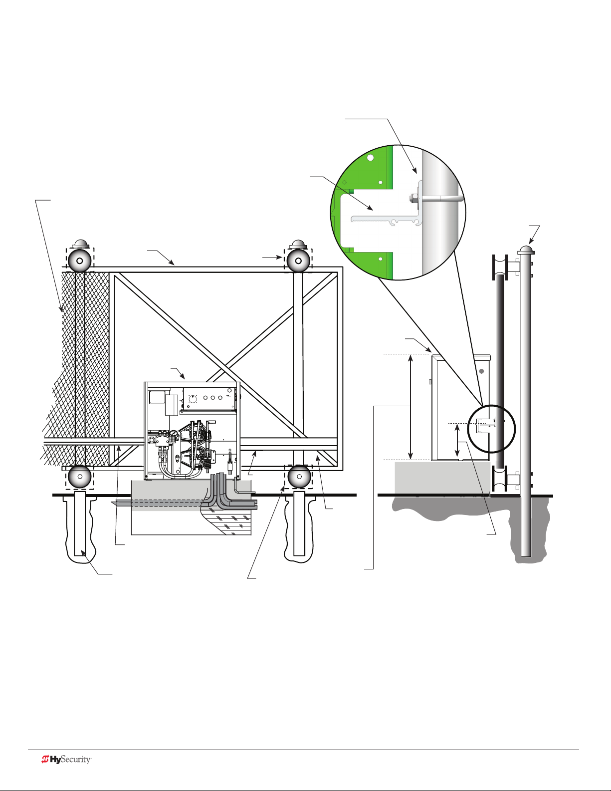
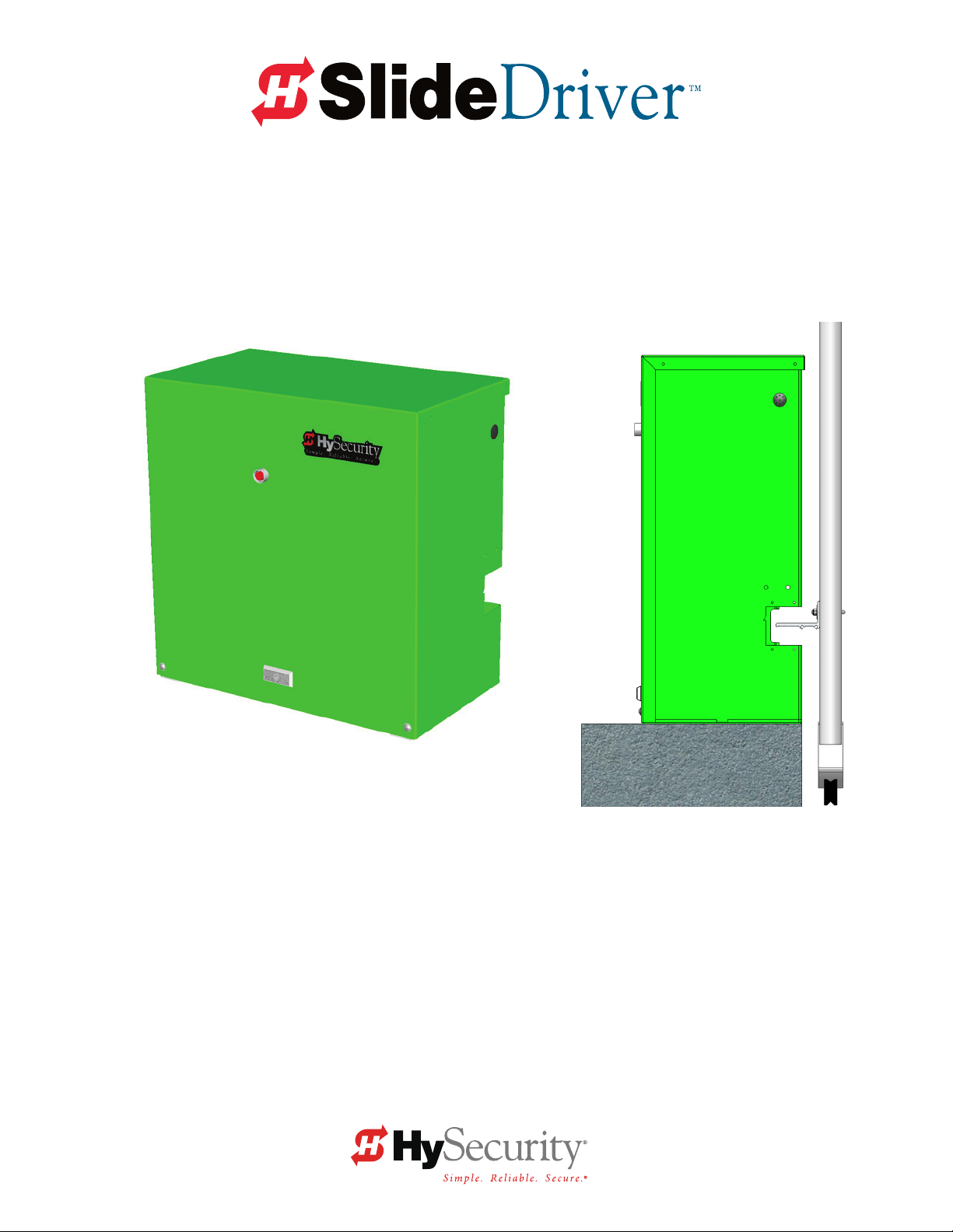
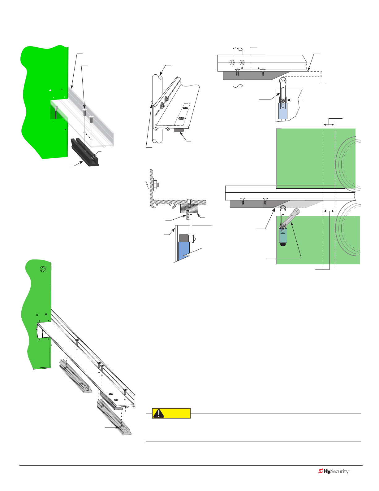
SlideDriver/SlideDriver 50VF
Site Installation Overview
Gate Face*
Use shims as needed
Grooved Drive Rail
Screen Safety Mesh on Gate Height: Per UL 325 and ASTM
F2200, all openings in a sliding gate up to a 72-inch (6 foot or
183 cm) height must be guarded or screened.
Support Post
Gate
SlideDriver
Concrete Pad
Drive Rail
Support Post
Wheel Cover
For clarity, safety mesh
is not shown
Limit
Ramp
Wheel Cover
SlideDriver
Drive
Rail
All models:
(except SD 200)
26" (66cm)
SlideDriver 200:
43¼" (109.5cm)
Height from top of
Drive Rail* to bottom
of gate operator.
All models:
9¼" (23.5cm) using standard AdvanceDrive™
wheels, 6 or 8 inch.
*NOTE: using XtremeDrive™ wheels, adjust
height along the length of the Drive Rail by
¼ to ½ inch which increases overall height
between 9¾ and 10 inches (24 to 25 cm).
ii D0559 Rev. A SlideDriver/SlideDriver 50VF Series www.hysecurity.com
Page 3
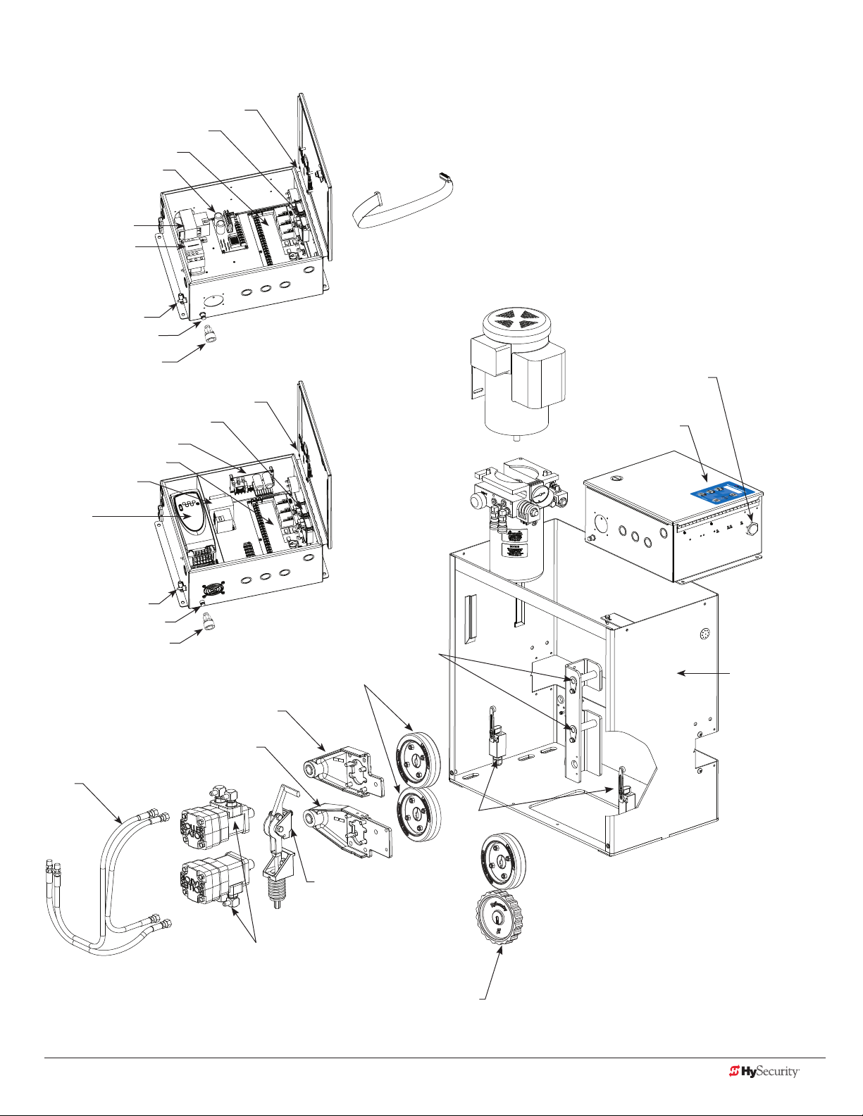
SlideDriver/SlideDriver 50VF Components
UC 2
USAGE CLASS
Board, Display
Detector, Vehicle
Board, Smart Touch
Board, Power Supply
Transformer
Contactor, Motor
Switch, Disconnect
Reset Switch, Internal
Reset Button, External
HY-5A Detector, Vehicle
Board, Power Supply
Board, Smart Touch
Transformer
Variable
Frequency Drive
(VFD) Power Unit
Switch, Disconnect
Reset Switch, Internal
Reset Button, External
Drive Arm, Motor Mount, Top
SlideDriver Control Box
Board, Display
SlideDriver 50VF Control Box
AdvanceDrive™ Wheel Kit
[Motor, Electric]
[Pump Pack]
Drive Arm, Pivot Kit
Cable, Ribbon
Buzzer, Piezo
Keypad
Chassis
Cover not shown
Drive Arm, Motor Mount, Bottom
Hose
Limit
Switches
Release,
Manual
Motor, Hydraulic
Combination AdvanceDrive
and XtremeDrive Wheels
www.hysecurity.com Introduction D0559 Rev. A iii
Page 4
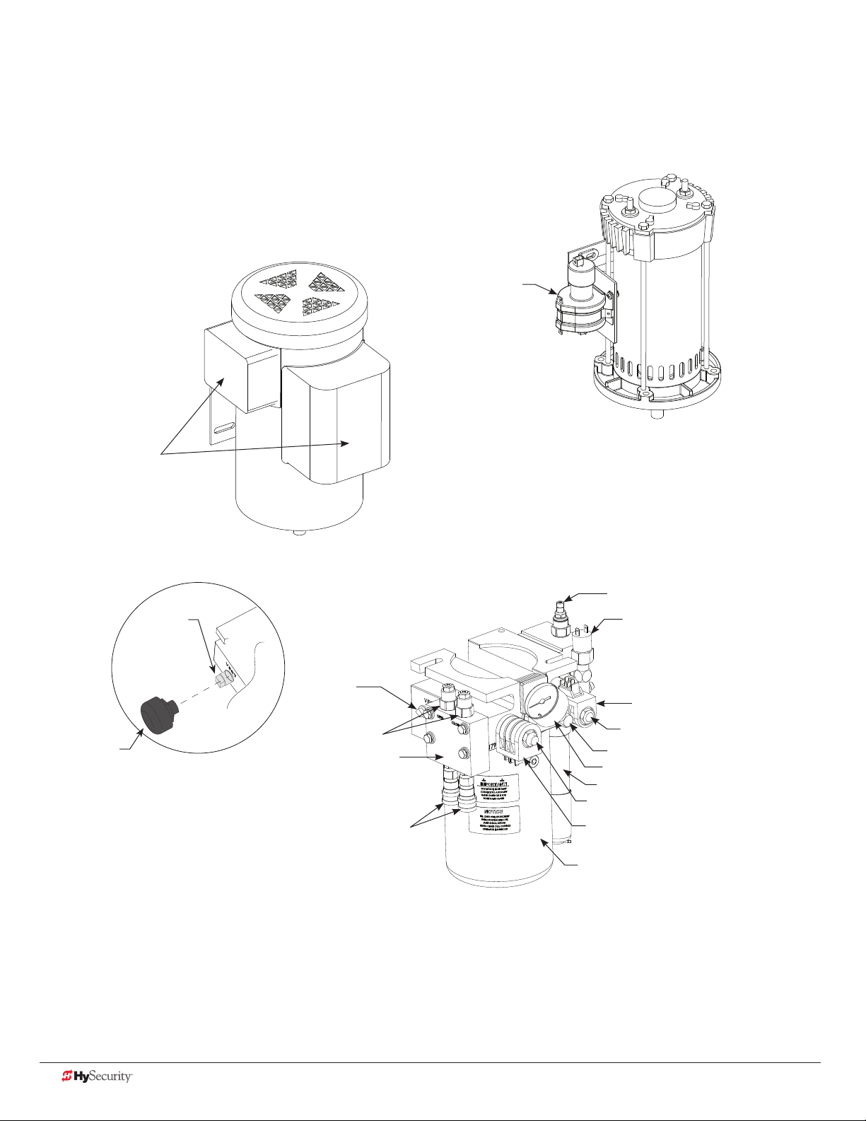
SlideDriver/SlideDriver 50VF Components
Motor, Electric, DC
Motor, Electric, AC
Contactor, Mercury
Motor Starting Kit
Breather cap
Vent plug
Vent plug
Valve, Braking
Braking Kit
Quick Disconnect, Socket
Valve, Relief
Sensor Kit, Inherent Entrapment
Valve Coil, Quick Stop
Valve, Quick Stop
Valve, Check, Endhead
Gauge, Pressure
AWOG
Valve, 2 Position Directional
Valve Coil, Directional
Reservoir
iv D0559 Rev. A SlideDriver/SlideDriver 50VF Series www.hysecurity.com
Page 5

Contents
SlideDriver Site Installation Overview ..............................................................................................................................ii
SlideDriver and SlideDriver 50VF Components ........................................................................................................ iii - iv
Welcome to HySecurity ...........................................................................................1
Contact Information .........................................................................................................................................................2
Notices and Bulletins .......................................................................................................................................................2
Supplemental Documents ................................................................................................................................................2
IMPORTANT SAFETY INFORMATION .............................................................................................................................3
Safety - Additional Installer Responsibility ....................................................................................................................4
Safety - Owner/User Responsibility ...............................................................................................................................6
Hazardous Materials and Proper Disposal .......................................................................................................................6
Identifying Gate Operator Category and Usage Class ....................................................................................................7
Choosing Secondary Entrapment Protection ...................................................................................................................8
Grounding, Breather Cap Installation & Handing ...........................................................................................................9
Emergency Stop Button ................................................................................................................................................10
Emergency Release .......................................................................................................................................................10
SlideDriver Slow Down Limit Ramps ...........................................................................................................................11
Safety Notices ................................................................................................................................................................12
Common Industrial Symbols ..........................................................................................................................................12
PoWer ..................................................................................................................13
Installing the Earth Ground ...........................................................................................................................................13
Site Considerations .....................................................................................................................................................14
Wiring AC Power ............................................................................................................................................................14
Turning the Power Switch ON .....................................................................................................................................15
Wire Sizing and Runs ......................................................................................................................................................16
Low Voltage Control Wiring ........................................................................................................................................16
SlideDriver Wiring Charts (Incoming Power) ...............................................................................................................17
SlideDriver 50VF-series Wiring Chart (Incoming Power) .............................................................................................19
Performance of 50VF-series Operators on 1 and 3 Phase, 50 or 60Hz.......................................................................19
Control Transformer Connections (Non-UPS) ...............................................................................................................21
Gate Operator Connections (Modular Unit) ..................................................................................................................21
DC Power Supply (UPS) Connections .............................................................................................................................22
www.hysecurity.com Table of Contents D0559 Rev. A v
Page 6

configure tHe oPerator ........................................................................................23
Gate Handing .................................................................................................................................................................23
Hydraulic Hose Swap .....................................................................................................................................................24
Adjusting the Pressure Relief Valve ................................................................................................................................24
The Inherent Entrapment Sensor (IES) ..........................................................................................................................26
Manufacturer’s responsibility .......................................................................................................................................26
Pressure Relief Valve – All Hydraulic Operators: ........................................................................................................26
Inherent Entrapment Sensor – (IES) ...........................................................................................................................27
ModBus RTU in SlideDriver 50VF-series ........................................................................................................................27
Emergency Fast Operate (EFO) in SlideDriver 50VF-series ...........................................................................................28
Setting the Emergency Fast Close ..............................................................................................................................28
Installing a Push-Button Device for EFC ....................................................................................................................28
Emergency Fast Close Speeds ...................................................................................................................................28
control Panel overvieW .......................................................................................29
SlideDriver Wiring Diagram, D0266 REV B ....................................................................................................................30
Variable Speed Drive (VFD) Control Box .......................................................................................................................31
Variable Speed Drive Wiring Diagram ...........................................................................................................................32
STC Board, Power Module and Display .........................................................................................................................33
DiSPlay & menu oPtionS ........................................................................................35
Initial Setup ....................................................................................................................................................................35
Understanding the Display and Keypad .......................................................................................................................35
Menu Mode and the STC Keypad ................................................................................................................................36
Menu Mode Navigation .................................................................................................................................................36
Run Mode and the STC Keypad ...................................................................................................................................37
Viewing Operator Status Displays ..................................................................................................................................37
Stop the Status Display Scrolling ................................................................................................................................38
Change the Display Contrast ......................................................................................................................................38
Check Time and Date .................................................................................................................................................38
User Menu ......................................................................................................................................................................39
User Menu: Table 1 ........................................................................................................................................................39
Installer Menu ................................................................................................................................................................41
Installer Menu: Table 2 ...................................................................................................................................................42
Setting the Close Timer .................................................................................................................................................47
Test the Operator ...........................................................................................................................................................48
vi D0559 Rev. A SlideDriver/SlideDriver 50VF Series www.hysecurity.com
Page 7

Stc inPutS & Wiring .............................................................................................49
Overview of the STC and Power Module .......................................................................................................................50
Integrating with Security Systems ..................................................................................................................................51
Smart Touch Controller Inputs........................................................................................................................................52
STC Terminal Inputs .......................................................................................................................................................52
Connecting Accessory Devices ......................................................................................................................................54
User Relays – Programming Procedure ..........................................................................................................................55
Hy8Relay Module Option ...............................................................................................................................................57
Vehicle Detector Logic ...................................................................................................................................................58
TailGate Alert .............................................................................................................................................................58
Anti-TailGate Mode Selection .....................................................................................................................................58
Vehicle Detector Installation: HY-5A ..............................................................................................................................59
Connecting HY-5A Vehicle Detectors .............................................................................................................................60
Photo Eyes (Non-Contact) Installation ...........................................................................................................................61
Compatibility ..............................................................................................................................................................62
Installation ...................................................................................................................................................................62
Conguration .............................................................................................................................................................62
Photo Eye Connections ..............................................................................................................................................63
Photo Eye Alignment ..................................................................................................................................................64
Monitored Connection ................................................................................................................................................64
Photo Eye Function .....................................................................................................................................................64
Dual gate SyStemS ................................................................................................65
Connecting an Interlocked Pair (Dual Gate) ...................................................................................................................65
Dual Gate Wiring Connections ...................................................................................................................................66
Dual or Sequenced Gates: Power, Software & Accessory Requirements ..................................................................67
Programming a Dual Gate (Interlocked Pair) .............................................................................................................67
Connecting Sequenced Gates .......................................................................................................................................68
Sequenced Gate: Conguration #1 ...............................................................................................................................70
Sequenced Gate: Conguration #2 ...............................................................................................................................71
troubleSHooting ...................................................................................................73
System Diagnostic Messages .........................................................................................................................................73
Troubleshooting Codes: Table 3 .................................................................................................................................74
Electrical Issues ..............................................................................................................................................................79
AC-Powered Gate Operators ......................................................................................................................................79
Mechanical Issues ...........................................................................................................................................................80
Hydraulic Issues ..............................................................................................................................................................80
Typical Problems and Troubleshooting Procedures .......................................................................................................81
www.hysecurity.com Table of Contents D0559 Rev. A vii
Page 8

general maintenance ...........................................................................................83
Smart Touch Analyze and Retrieve Tool (S.T.A.R.T.) .......................................................................................................83
What You Need ...........................................................................................................................................................83
Installing S.T.A.R.T. Software .......................................................................................................................................83
Software Maintenance ....................................................................................................................................................84
Electrical Controls ..........................................................................................................................................................85
Clock Battery Replacement ........................................................................................................................................85
Mechnical Controls.........................................................................................................................................................85
Stopping the Gate .....................................................................................................................................................85
Starting the Gate .......................................................................................................................................................85
Mechanical Maintenance ...............................................................................................................................................86
Drive Rail .....................................................................................................................................................................86
Drive Wheel Spring Tension (Adjustment of Manual Release) ....................................................................................87
Grooved Drive Rail .....................................................................................................................................................88
Drive Wheel Assembly ................................................................................................................................................89
Hydraulic System Maintenance ......................................................................................................................................90
Brake Valve Adjustments ............................................................................................................................................91
Pressure Relief Valve Adjustments ..............................................................................................................................91
Open Valve .................................................................................................................................................................91
SlideDriver Operator Maintenance Schedule ................................................................................................................92
SlideDriver Installer Checklist .........................................................................................................................................93
Specications .................................................................................................................................................................96
viii D0559 Rev. A SlideDriver/SlideDriver 50VF Series www.hysecurity.com
Page 9

Welcome to HySecurity
Thank you for purchasing our premium SlideDriver™ gate operator. HySecurity Gate, Inc. has manufactured some
of the nest, sturdiest, most innovative, and reliable hydraulic gate operators since the 1970s. We use the same
hydraulic technology common in the aircraft industry while incorporating software capabilities that far exceed the
competition.
All operator designs are tested for hundreds of thousands of cycles before being released to the market. Slide,
swing, trafc barrier, fortied crash barrier gate and vertical lift operators have all received rigorous testing and
certication. Security, low maintenance, exible conguration, and overall toughness are the foremost criteria for
all HySecurity products.
Our commitment to quality and innovation will become evident as the features and performance of the expertly
engineered and manufactured SlideDriver become familiar to you. Thank you again for the condence you’ve
shown in becoming part of the HySecurity family and in choosing a premium, industry-leading product.
HySecurity Gate, Inc. Headquarters in Kent, WA
www.hysecurity.com Safety D0559 Rev. A 1
Page 10

ContaCt InformatIon
Qualied HySecurity distributors are experienced and trained to assist in resolving any problems. For the name of
a qualied distributor near you, call HySecurity at 800-321-9947.
Before contacting your distributor or HySecurity Technical Support, obtain the serial number of your operator.
For information about HySecurity training for installers, maintenance personnel, and end users, refer to the
company website at www.hysecurity.com.
notICes and BulletIns
Installers should visit HySecurity’s online Technical Support page at www.hysecurity.com or contact HySecurity
prior to installing product to make sure they have received the most up-to-date information.
supplemental doCuments
The product literature is comprehensive and contains information needed to plan, install, operate and maintain
your gate operator. Additional general information concerning HySecurity gate operators can be obtained from
the following:
• HySecurity website www.hysecurity.com - Contains links to the product catalog, product order form,
operator manuals, operator software downloads, technical support bulletins and other useful information.
• S.T.A.R.T. - Smart Touch Analyze and Retrieve Tool - User’s Guide (D0049) detailing the extensive software,
diagnostic and troubleshooting capabilities of the Smart Touch Controller board.
• Technical Bulletins (as applicable).
NOTE: Technical Bulletins are automatically issued to registered users of HySecurity products. The
product warranty registration card can be lled out online at www.hysecurity.com.
2 D0559 Rev. A SlideDriver/SlideDriver 50VF Series www.hysecurity.com
Page 11

Important safetY InformatIon
WARNING
Read all the product safety information prior to installation. Automatic gate operators move the gate with high
force and can cause serious injury and death! Make sure the automatic gate operator is installed to reduce the
risks of entrapment. Verify the gate operator is installed to comply with all safety standards and local and federal
regulations.
Understand that you as the site designer, installer, maintenance crew, or owner/user must consider the risks
associated with gate operators. Be sure to take responsibility, read, and follow the Important Safety Information
in this manual and review all the literature that accompanies the product.
Hazards, associated with automatic gates, can be reduced with proper site design, installation, and use. Installers,
maintenance crews, and owners/users must read and follow the safety requirements found in the HySecurity
product manuals.
It is important that only qualied installers handle the installation of the HySecurity equipment and gate operator.
A “qualied” installer has one of the following:
• A minimum of three years experience installing similar equipment
• Proof of attending a HySecurity Technical Training seminar within the past three years
• Signicant manufacturer endorsements of technical aptitude in gate operator installation and operation
Underwriter Laboratories (UL) and the American Society for Testing and Materials (ASTM) are responsible for
current safety standards and regulations regarding automatic vehicular gate operators. To pass certication, all
aspects of gate operator and gate installation must comply with the appropriate safety standards.
For the most up-to-date ASTM F2200 Gate and Fence Standards, refer to www.astm.org.
For UL 325 Safety Standards, refer to www.ul.com.
www.hysecurity.com Safety D0559 Rev. A 3
Page 12

WARNING
A moving gate or barrier arm, bollard, or wedge can cause serious injury or death.
To reduce the risk of injury or death:
1. READ AND FOLLOW ALL INSTRUCTIONS. Read the gate operator’s product manual and review all the
product labels and literature prior to installing, operating, or maintaining the automatic gate operator.
2. Never let children operate or play with gate controls. Keep all remote controls, especially radio
transmitters, away from children. Do not allow children to play on or around the gate or gate operators.
3. Always keep people and objects away from the gate. NO ONE SHOULD CROSS THE PATH OF THE
MOVING GATE. Start the gate operator only when a gate’s travel path is clear.
4. Test the gate operator monthly. The gate MUST reverse on contact with a rigid object or stop when an
object activates the non-contact sensors. After adjusting the force or the limit of travel, retest the gate
operator. Perform routine tests of the entrapment protection sensors, such as photo eyes and gate edges.
Failure to adjust and retest the gate operator properly can increase the risk of injury or death.
5. Use the emergency release only when the gate is not moving.
6. KEEP GATES PROPERLY MAINTAINED. Read the product manuals. Have a qualied service person make
repairs to gate hardware and replace batteries in accessory or entrapment sensory devices on a regular
basis.
7. The automated gate entry is for vehicle use only. Pedestrians must use a separate entrance. Make sure a
separate walk-through entrance is nearby. Make certain a clear pedestrian path is designated and signs
direct pedestrians to the walk-through gate.
8. Install the supplied WARNING signs on the inside and outside of the gate or barrier gate/operator so they
are clearly visible from both the secure and public sides. Installing the signs is a requirement for UL 325
compliance.
Safety - Additional Installer Responsibility
• Verify the gate operator usage class for the site. For all gate operators other than Crash-rated, refer to
Identifying Gate Operator Category and Usage Class in this product manual. Install the operator only
when the gate operator class is correct for the site, size, and type of gate.
• The gate operator must be properly grounded and the incoming power voltage must match the voltage
label on the junction box.
• Install an automatic operator only on gates that comply with ASTM F2200 Gate and Fence Standards.
Screen or enclose openings in the gate per UL 325 Safety Standards which include:
All horizontal slide gates must guard or screen openings from the gate’s base support to a minimum
height of 6 feet (183 cm) above the ground. This must prevent a sphere of 2¼-inches (57 mm) in
diameter from passing through an opening in the gate or the adjacent fence that is covered in the
gate’s open position.
Physical stops must exist in the gate construction to prevent over-travel in both directions and, for
slide gates, guard posts must be installed to prevent the gate from falling in the event of a roller
failure.
4 D0559 Rev. A SlideDriver/SlideDriver 50VF Series www.hysecurity.com
Page 13

Safety - Installer’s Responsibility, continued
• Before attaching the operator to the gate, move the gate or barrier gate in both directions. Make sure it
is level and moves freely. A gate or barrier gate that moves easily reduces strain on operator components.
Gravity should play no part in the opening or closing of a slide gate.
• Never over-tighten a clutch or pressure relief valve to compensate for a stiff or damaged gate.
• Make sure all exposed pinch points, rollers and wheels are guarded.
• Reduce the risk of entrapment throughout the entire travel path by making sure the gate is installed in a
location which ensures the required clearance between the gate and adjacent structures when opening
or closing. On slide gates, minimize the parallel gap between the gate and the fence.
• Install the gate operator on the secure (non-public) side of the gate. Note that swing gates cannot open
into public areas.
• Install external entrapment protection sensors so pedestrians are protected from entrapment in both
directions of gate travel and all hazard areas are fully protected. On hydraulic gates, set the pressure
relief valve at the lowest allowable setting that will reliably operate the gate. The pressure relief valve
controls the applied force of the operator and the sensitivity of the inherent entrapment sensor (IES).
Note that no IES exists in the StrongArm operator.
• Never disable the Warn Before Operate buzzer. This buzzer provides an alert that the gate is about to
move.
• Mount access control devices beyond reach of the gate. The control devices that operate the gate must:
Be located in a clear line of sight to the gate. Locate controls (Open, Close, Stop/Reset) where a user
will have a clear view of the gate.
Be mounted beyond 6 feet (183 cm) of the gate, to prevent users from touching or accessing the gate
while operating the controls. People attempting to access the controls by reaching through or around
the gate can be seriously injured or killed by the moving gate.
Incorporate a security feature to prevent unauthorized use.
Connect radio and other remote access (non-resetting controls) to the RADIO OPTIONS terminal.
• Open and close the gate to conrm that it was properly installed and to ensure reduced risk of
entrapment. Verify the clearance between the gate and adjacent structures per UL 325 Safety Standards.
Have a qualied technician test the gate monthly.
• When you complete the installation, demonstrate the safety features and operation of the gate operator
to the end user:
Clearly explain and demonstrate the consequences of removing or defeating any of the safety
features.
Remove the operator cover(s), and then turn the power on and off.
Manually release the gate. (Use the manual release only when the gate is NOT moving.)
Use the Emergency Stop Button. (If an emergency stop button is not available, show the user where
the Stop button is located on the gate operator.)
NOTE: Gate operator instructions must be given to the owner per UL 325 Safety Standards.
Take photographs of the completed installation site and save it in your business les.
www.hysecurity.com Safety D0559 Rev. A 5
Page 14

Safety - Owner/User Responsibility
CAUTION
As the owner/user, you are responsible for the correct and safe installation, operation and maintenance of the
SlideDriver gate operator. It is of the utmost importance that you read and follow the specic instructions and
precautions found in the IMPORTANT SAFETY INFORMATION addressed in this manual. In addition, you must
adhere to the safety standards of applicable federal, state, and local safety regulations, industry standards, and/
or procedures.
NOTICE: For installations outside the United States, make sure that you follow the applicable international,
regional, and local safety standards.
• Automatic gates are for vehicular use only; provide and maintain walkways and signs to direct pedestrians
to a separate walk-through entrance.
• An automatic gate can start at any time without warning; always keep people away from the gate area.
• Never let children operate or play with gate controls. Keep all remote controls, especially radio
transmitters, away from children. Do not allow children to play on or around the gate, gate area, or
gate operators.
• Learn how to turn the power on and off. Learn how to manually operate the gate.
• WARNING signs supplied with the gate operator must remain installed and clearly visible on both sides
of the gate. The signs are required to maintain UL 325 compliance.
• Do not physically disable the warning buzzer and NEVER disconnect or cut its wires. The buzzer provides
compliance with the Manual on Uniform Trafc Control Devices (MUTCD) standards. Disabling the
warning buzzer may increase the risk of death or serious injury.
• Do not remove entrapment devices or any other safety features.
• Have a professional gate installer routinely inspect the gate hardware and test the entrapment protection
sensors and overall gate operation. Have a qualied service person make repairs to gate hardware and
equipment to keep the gate running smoothly.
Hazardous materIals and proper dIsposal
Be aware of the international, federal, and local codes in your area and how best to handle hazardous waste
materials.
The pump pack uid, found in all hydraulic HySecurity operators, can be recycled. Gear oil, found in HySecurity
electromechanical gate operators, can also be recycled. If the uids are mixed or contaminated with any solvents
or other chemicals, they become hazardous waste. Hazardous waste requirements for storage and disposal must
be followed.
If the gate operator has a battery backup system, the batteries contain materials that are considered hazardous
to the environment. Proper disposal of the battery is required by federal law. In the U.S.A., refer to federal EPA
guidelines for proper hazardous waste disposal.
6 D0559 Rev. A SlideDriver/SlideDriver 50VF Series www.hysecurity.com
Page 15
IdentIfYIng gate operator CategorY and usage Class
The SlideDriver operator, according to UL 325 Safety Standards, falls in the horizontal slide, vertical lift and
vertical pivot category for gate operators. Its usage class is determined by the area that the vehicular gate
services.
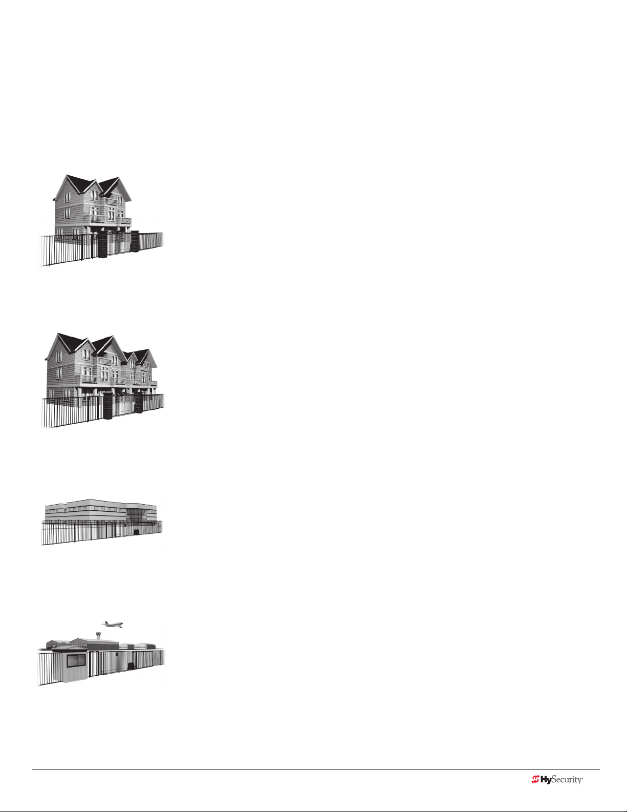
Four different vehicular usage classes are dened by UL 325:
Class I
Class I: Intended for use in garages or parking areas associated with a residence
of one to four single families.
Class II
Class II: Intended for use in a commercial location or building such as a multifamily housing units (ve or more single family units) hotels, garages, retail stores
or other buildings accessible by or intended to service the general public.
Class III
Class IV
Class III: Intended for use in an industrial location or building such as a factory
or loading dock or other locations NOT accessible by or intended to service the
general public.
Class IV: Intended for use in a guarded industrial location or building such as an
airport security area or other restricted access locations, not servicing the general
public, in which unauthorized access is prevented via supervision by security
personnel.
www.hysecurity.com Safety D0559 Rev. A 7
Page 16
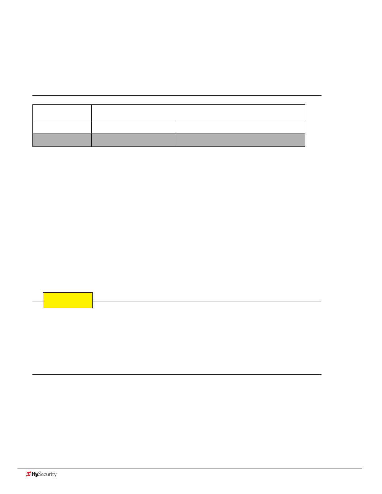
CHoosIng seCondarY entrapment proteCtIon
CAUTION
The site designer or installer must determine which secondary entrapment sensor devices will be installed with
the SlideDriver operator to meet UL compliance. The type of entrapment sensor device systems are described
below. For a complete listing of the requirements, refer to UL 325 Safety Standards.
NOTICE: SlideDriver is equipped with a primary, Type A, inherent entrapment sensor (IES) that complies with
UL 325. Any impediment to gate travel causes the gate to stop and reverse.
Usage Class Primary Type Device Secondary Type Device
Class I, II, III A B1, B2, C, or D
Class IV A B1, B2, C, D, or E
To comply with UL 325, refer to the chart and take the following steps:
1. Select the Usage Class according to the gate’s locale and purpose.
2. The required UL 325 primary Type A sensor is an integral part of the SlideDriver system.
3. Based on the gate’s usage class, choose Secondary Type Devices: B1, B2, C, D, or E.
• To comply using B1 - install non-contact sensors (photoelectric sensor or the equivalent).
• To comply using B2 - install contact sensors (edge sensor device or the equivalent).
• To comply using a Type D device requires a CONSTANT HOLD push-button station. This CONSTANT
HOLD push-button station must be the only device that opens and closes the gate. It can only be used
where the gate and push button station will be monitored by personnel 24 hours a day in full view of
the gate area. An automatic closing device (such as a timer, loop sensor, or similar device) must not
be employed. A Warning placard stating, “WARNING - Moving Gate has the Potential of Inicting
Injury or Death - Do Not Start the Gate Unless the Path is Clear” must be placed adjacent to the gate
operator controls.
While compliance is possible with Type C, which is a low force limiting clutch, the SlideDriver operator does not
utilize a clutch, therefore this option is not available.
Similar compliance issues exist with a Type E device (audio warn before operate alarm). A Type E device is
permitted as a means of secondary entrapment protection by UL 325 in Class IV applications, but it is not
recommended by HySecurity because a buzzer warns, but cannot protect against possible entrapment.
HySecurity highly recommends, even for Class IV use, that secondary entrapment protection (edge or photoeye sensor) devices be installed to detect possible entrapment.
8 D0559 Rev. A SlideDriver/SlideDriver 50VF Series www.hysecurity.com
Page 17
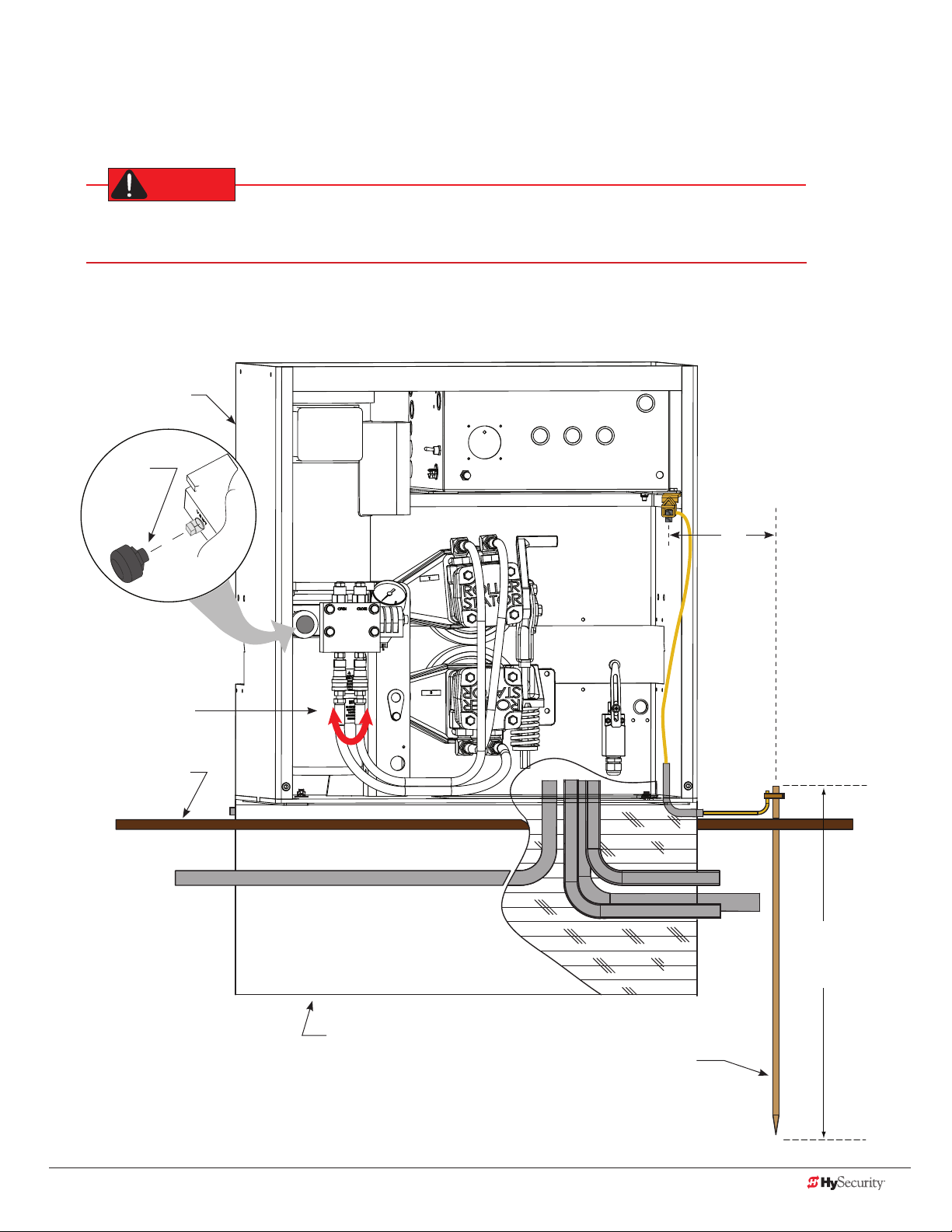
groundIng, BreatHer Cap InstallatIon & HandIng
DANGER
The gate operator has a vent plug that keeps the hydraulic uid from spilling during shipment. The vent plug
must be replaced by the breather cap before operating the slide gate.
Failure to perform the following procedure will cause premature pump shaft failure and void the
Limited Warranty.
1. Remove the vent plug and discard it.
2. Replace the vent plug with the breather cap.
SlideDriver
Replace red vent plug
with breather cap
Operator is shipped
hydraulically congured
for “right hand” operation.
Refer to “Gate Handing”
on page 23.
Swap hydraulic hoses for
left handling.
Grade level
Cut-away view
3 ft
(91.4 cm)
Maximum
distance
Consult local
codes for
proper depth
Concrete foundation
Ground rod
www.hysecurity.com Safety D0559 Rev. A 9
Page 18
emergenCY stop Button
WARNING
WARNING
Make sure all users of the gate know where the emergency stop button
is located (see illustration). It complies with UL 325 Safety Standards
requirements.
Pressing the emergency stop button while the gate is opening or
closing disables the automatic close timer and stops gate travel. Gate
travel remains stopped until the operator receives another open or
close signal.
Emergency Stop button
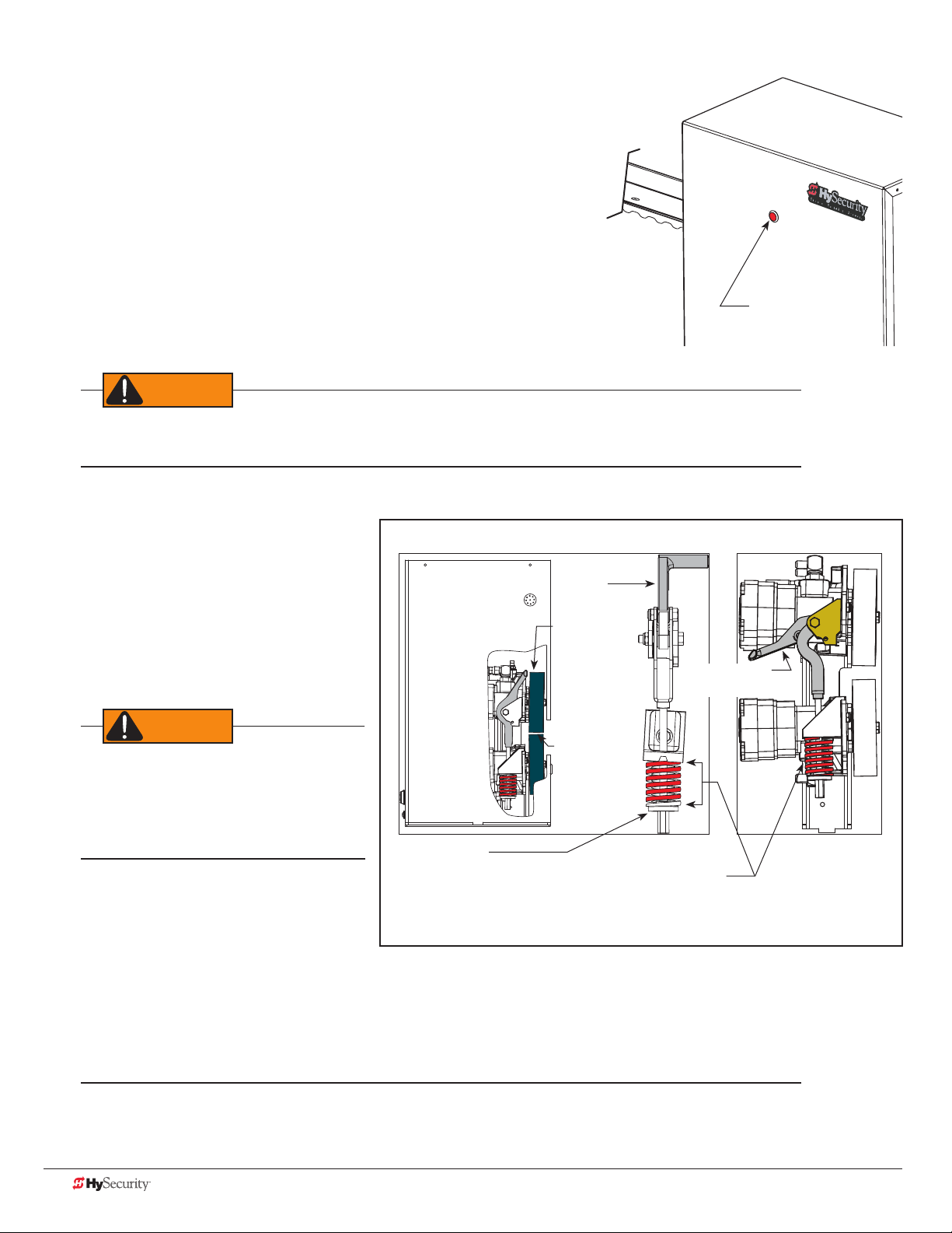
emergenCY release
Before attempting a manual release, make sure the gate is not in motion and power is disconnected
(turned OFF).
Make sure and teach all users how to turn off electric power and how to move the gate manually. To prepare for
manual operation, power must turned off
and the drive wheels must be released
Note: Drive Rail must be aligned and secured before adjusting wheel loading
Know the weight of the gate you are
Toggle Handle
clamped
moving. Excessively heavy gates can be
difcult to move and may cause serious
Drive Wheels
injury to those involved in moving the
gate. Take the necessary precautions when
manually moving any gate.
When releasing the handle inside the
chassis, be careful as the mechanism is
spring-loaded and drops rapidly. Hold the
handle appropriately so your ngers do not
get injured or pinched.
To disengage the drive wheels from the
drive rail and manually move the gate, take
the following steps:
Coupling Nut:
Adjusts compression spring.
Drive Rail
slides between
drive wheels
Compression Spring:
Controls drive wheel gripping force. Set at 2 in.
(5cm) when Drive Wheels are clamped on the
Drive Rail. Toggle handle is in the clamped (load)
position.
Toggle Handle
unclamped
1. Remove the front chassis cover and set it aside.
2. Pull the toggle handle down. The manual release is located under the electric control panel and to the
right of the hydraulic motors.
NOTE: For more information, refer to “Drive Wheel Spring Tension (Adjustment of Manual Release)” on page 87.
Other types of release mechanisms exist. For example, the Fire and Emergency Access Lock Box is available
through HySecurity distributors. Contact your distributor for more information.
10 D0559 Rev. A SlideDriver/SlideDriver 50VF Series www.hysecurity.com
Page 19
slIdedrIver slow down lImIt ramps
CAUTION
Drive rail
Round-head bolts:
3/8 " (9 mm)
Must be fully
tightened and ush
before adjusting
limit switch.
4"
10 cm)
Nut
Standard Limit Ramp
The standard limit ramp is positioned
on the drive rail so it will make
contact with the limit switch and stop
approximately 2 inches (5 cm) from the
drive wheel.
Limit ramps are attached to the
underside of the drive rail when the
gate is fully open and fully closed.
Chassis
cutout
U-bolt
Roller
Support
Post
Limit Ramp
Limit Ramp
4" (10 cm)
Spacing approximate
Limit
Switch
Limit Ramp
enters chassis
cutout
Actuating Arm
(Tripped position)
Base of Drive Rail
3/8 " (9 mm)
Height
Adjusting
Screw
2"
(5 cm)
Drive
Wheel
2" (5 cm)
Nut
SlideDriver 50VF
Slow Down Limit Ramp Kit
Two truss head screws secure each limit ramp to the drive rail. The bolts
are spaced about 4 inches (10 cm) apart.
The limit switch must be set ⅜-inch (9 mm) from the base of the drive
rail. A screw on the limit switch allows for slight adjustments in height. If
XtremeDrive wheels are used, you will need to raise the drive rail
¼ to ½ inch (3 to 13 mm) along the gate uprights and the entire
drive rail path. The limit switch placement will need to be adjusted
accordingly.
All the limit ramps are the same length.
NOTE: For a 50VF-series SlideDriver, you will need to order four (4)
Slow Down Limit Ramp Kits.
Be sure to securely fasten all limit ramps to the underside of the
drive rail when installing a 50VF-series operator.
www.hysecurity.com Safety D0559 Rev. A 11
Page 20
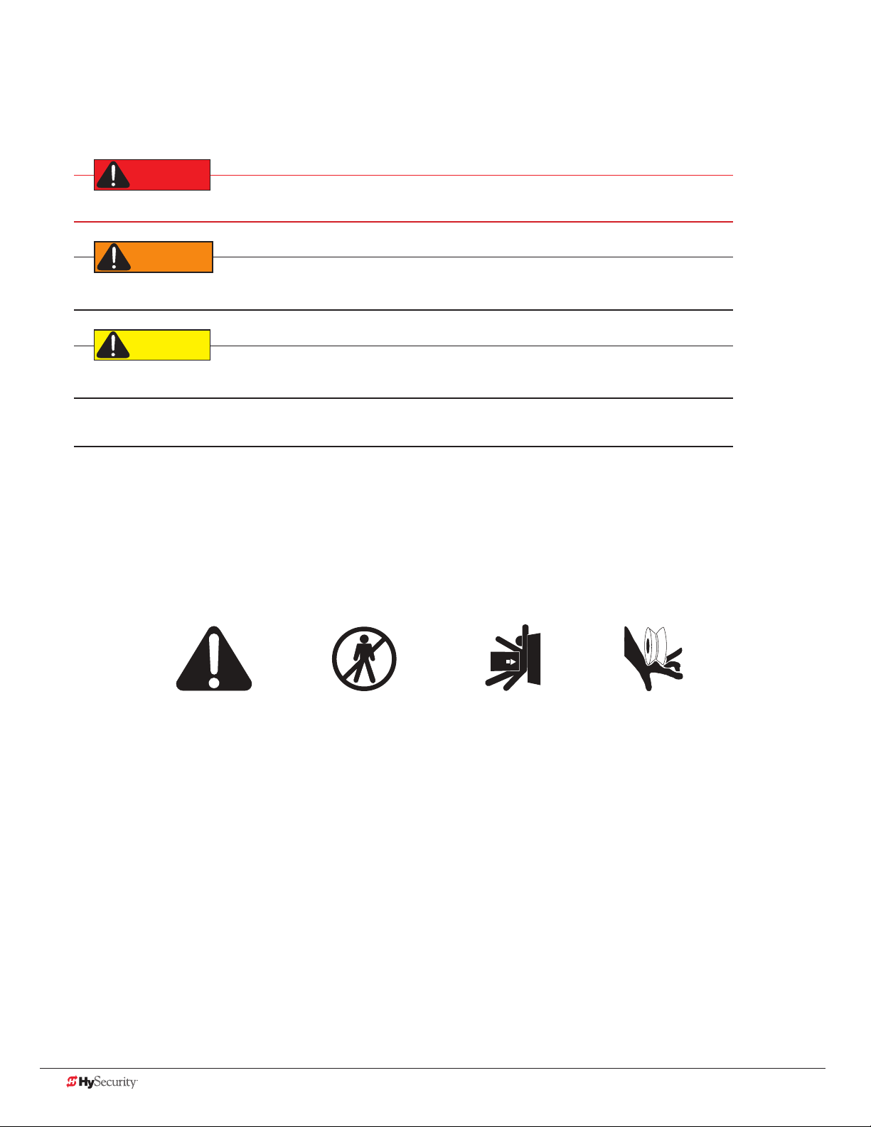
safetY notICes
DANGER
WARNING
CAUTION
- Take Note -
Keep Away
Zone
Pinch Point
The following four levels of safety notices are used where applicable within this manual; each notice contains
information specic to the situation.
Indicates death or serious injury will occur if the hazardous situation is not avoided.
Indicates death or serious injury could occur if the hazardous situation is not avoided.
Indicates mild or moderate injury could occur if the hazardous situation is not avoided.
NOTICE: Indicates damage to equipment is probable if the hazardous situation in not avoided.
Common IndustrIal sYmBols
The following international safety symbols may appear on the product or in its literature. The symbols are used
to alert you to potential personal injury hazards. Obey all safety messages that follow these symbols to avoid
possible injury or death.
Attention
- Danger -
Entrapment
Possible
12 D0559 Rev. A SlideDriver/SlideDriver 50VF Series www.hysecurity.com
Page 21
Power
DANGER
How to wire the operator is presented in the Installation Instructions, but detailed information about the earth
and equipment ground, wiring to AC power and the availability of UPS systems are described in this section.
Supplemental documents to this section include:
• DC Power Supply supplemental manual
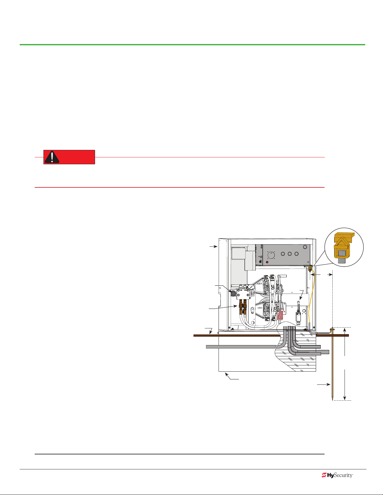
InstallIng tHe eartH ground
An earth ground refers to the grounding rod and accompanying equipment ground which need to be installed to
safeguard against potential electrical shock and damage to personnel and equipment.
The potential for lightning discharge exists with all gates, fences and gate operators. National Electric
Code (NEC) - Article 250 requires a separate earth ground in addition to the required equipment ground.
HySecurity recommends grounding the operator with a separate earth ground rod (or a similar device
in the case of crash products) to shield the operator against electromagnetism and other electrical signals that
may cause, erratic operation with, or damage to, the Smart Touch Controller and other electrical parts.
For earth grounding requirements in the U.S.A.,
refer to the National Fire Protection Association
(NFPA) 780 - Standard for the Installation of
Lightning Protection Systems. Highlights of the
standard include:
• The ground rod must be UL listed copperclad steel, solid copper, hot-dipped
galvanized steel, or stainless steel. Minimum
requirements: ½ inch (13 mm) diameter and
8 feet (244 cm) in length.
• The ground rod is driven into the earth
(refer to local codes for proper depth
requirements).
• The ground rod is electrically bonded to the
chassis with a single length of un-spliced
6AWG copper wire less than 3 feet (91 cm)
long. Due to the large concrete foundation
on crash products, make the necessary
adjustments to accommodate for earth
ground requirements.
• Local jurisdictions may impose other
requirements above the NEC, Article 250 and NFPA 780. Consult
the local codes and regulations regarding requirements in your area.
SlideDriver
Chassis
Breather Cap
Quick
Disconnects
Grade
level
Cut-away view
Concrete foundation
Control Box
Toggle Handle
Limit
Switch
Earth ground
3 ft
(91.4cm)
Maximum
distance
Ground lug
Consult local
codes for
proper depth
NOTICE: Properly grounding the gate operator is critical to gate operator performance and the life of its
electrical components. Use sufcient wire size during installation. If you do not ground the operator with a
separate earth ground, you risk voiding the HySecurity Limited Warranty.
www.hysecurity.com Power D0559 Rev. A 13
Page 22

Site Considerations
WARNING
HySecurity gate operators are intended for permanent installation. Make sure you prepare the site with the
following considerations:
• Make sure all electrical wiring is properly routed via conduits.
• Check the distance of the wiring run from the main panel to the gate operator. Make sure the wire size
of the branch circuit supplying power to the gate operator is large enough to avoid excess voltage drop.
Refer to “Wire Sizing and Runs” on page 16.
• Make sure the available power source matches the electrical requirements specied on the voltage
nameplate.
Each gate operator is built to run on a specic line power voltage and phase. Failure to ensure the source
voltage, phase and frequency match what is specied for the equipment, may result is severe damage to the
equipment.
• Make sure a 20-amp circuit (minimum) protected with a 20-amp Inverse Time Breaker is provided for all
AC power connections.
• Verify that the operator is electrically grounded per NFPA 780 and NEC Article 250, and local codes.
wIrIng aC power
The SlideDriver has separate Installation Instructions that explain how to connect to AC power. For reference
purposes, the same information is provided below.
In-rush Current: The current needed to start the electric motor spinning in the proper direction (CCW). It may
take as much as 6 to 9 times the run current to start one of the heavy duty operators.
NOTE: Use a 20A (minimum) slow kick (thermal) circuit breaker for all AC motors.
Size the primary wires. Consider the voltage, horsepower, and length of the wire run from the main power panel.
Make sure you have the proper voltage and conversion of voltage taps at the motor and transformer.
DANGER
Turn OFF AC power at the source (circuit breaker panel) before accessing the wires in the SlideDriver.
Follow facility Lock Out/Tag Out procedures. Make sure all power switches are in the OFF position. Follow
all electrical code standards and regulations.
14 D0559 Rev. A SlideDriver/SlideDriver 50VF Series www.hysecurity.com
Page 23
1. Connect to Power: Three wires and a ground are available for connection to a 3 Phase power source
WARNING
(3Ø). Loosen the screws on the power module to open the wire slots at the top and bottom.
2. Connect AC Power: Place the incoming power wires into their appropriate slots. Attach the ground wires
to the chassis. A wiring diagram is provided in the appendix.
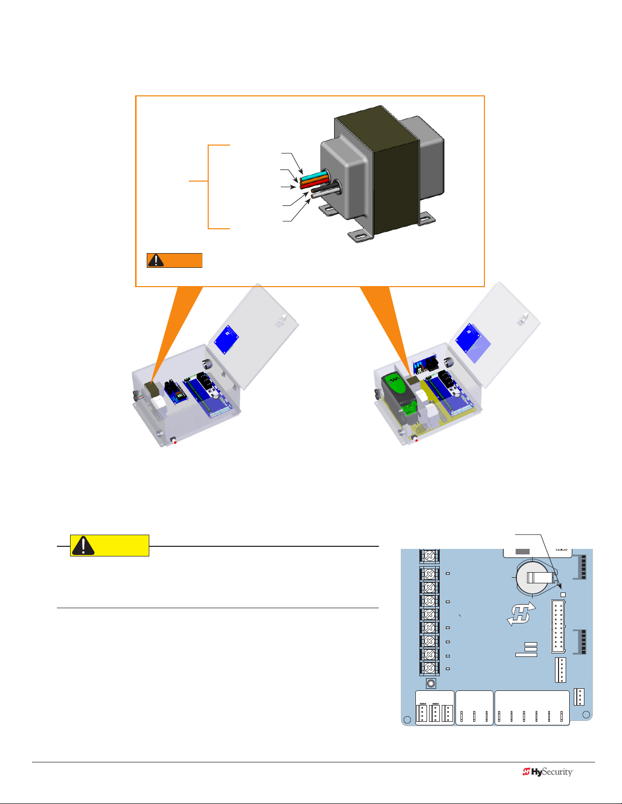
Blue - 480 VAC
Orange - 240 VAC
Input taps
connection wires match the voltage found on the operator’s nameplate.
Red - 208 VAC
Black - Common
White - 120 VAC*
Control Transformer
* Variable Frequency (VF) or 2 hp gate operators:
Never connect to the white 120V wire. Make sure the
All (Excluding SD50VF) SD50VF - series
CAUTION
Wiring of gate operators must conform to NFPA and NEC standards and
comply with all local codes. When the installation is compliant and complete,
turn on AC power at the source and at the control box.
Turning the Power Switch ON
The AC power disconnect switch is located on the same enclosure
(control box) where the electrical components, Smart Touch
Controller, transformer, power module, etc., are found.
When power is turned ON, a green status light on the Smart Touch
Controller blinks. The status light appears below the coin battery and
indicates that the processor is receiving power. For more information,
refer to “Smart Touch Controller Inputs” on page 52.
Green LED ashes indicating
processor is receiving power.
LED
RPM
DO NOT USE
PHOTO EYE
OPEN DIRECTION
DO NOT USE
PHOTO EYE
CLOSE DIRECTION
DO NOT USE
CHARGER
AC LOSS
LOCK INTERLOCK
EMERG CLOSE
FIRE DEPT OPEN
16
17
18
19
20
21
22
23
24
LIMIT DUAL GATE
HySecurity
MX000585
VERSION
S/N
Smart Touch Controller
RADIO OPTIONS
COM COMA B
VEHICLE DETECTOR
STATU S
SHADOW
RESET
DISPLAY
RS232
VEHICLE DETECTOR
WIEGAND
COMOPEN EDGE+24V +24V
www.hysecurity.com Power D0559 Rev. A 15
Page 24

wIre sIzIng and runs
Supplying a gate operator with the correct electrical service is crucial to the performance of the operator and
the life of its electrical components. If the wire size used is too small, the voltage loss, especially during motor
startup, will prevent the motor from attaining its rated horsepower. The percentage of horsepower lost is far
greater than the percentage of voltage loss.
A voltage loss can also cause the control components to chatter while the motor is starting, substantially reducing
their life due to the resultant arcing. There is no way to restore lost performance resulting from undersized wires,
except to replace them. Be sure to choose a sufcient wire size at initial installation to avoid costly rewiring. Refer
to “Wire Sizing and Runs” on page 16.
The tables on the following page are based on copper wire and allow for a 5% voltage drop. The ampere values
shown are the service factor ampere rating (maximum full load at continuous duty) of the motor. A 20A circuit
(protected with a 20A Inverse Time Breaker) should be provided, at minimum.
Always connect electrical power and ground the operator in accordance with the NFPA 780 & NEC, Article 430
and Article 250. Research and adhere to other local codes that may apply.
Low Voltage Control Wiring
The Smart Touch Controller has very sensitive control inputs. The following is a chart of maximum distances for
wire size:
Wire Size Maximum Distance
18 ga 7.0 miles (11 km)
20 ga 3.5 miles (5.6 km)
22 ga 2.7 miles (4.3 km)
24 ga 2.0 miles (3.2 km)
26 ga 1.0 mile (1.6 km)
28 ga 3700 feet (1.1 km)
16 D0559 Rev. A SlideDriver/SlideDriver 50VF Series www.hysecurity.com
Page 25
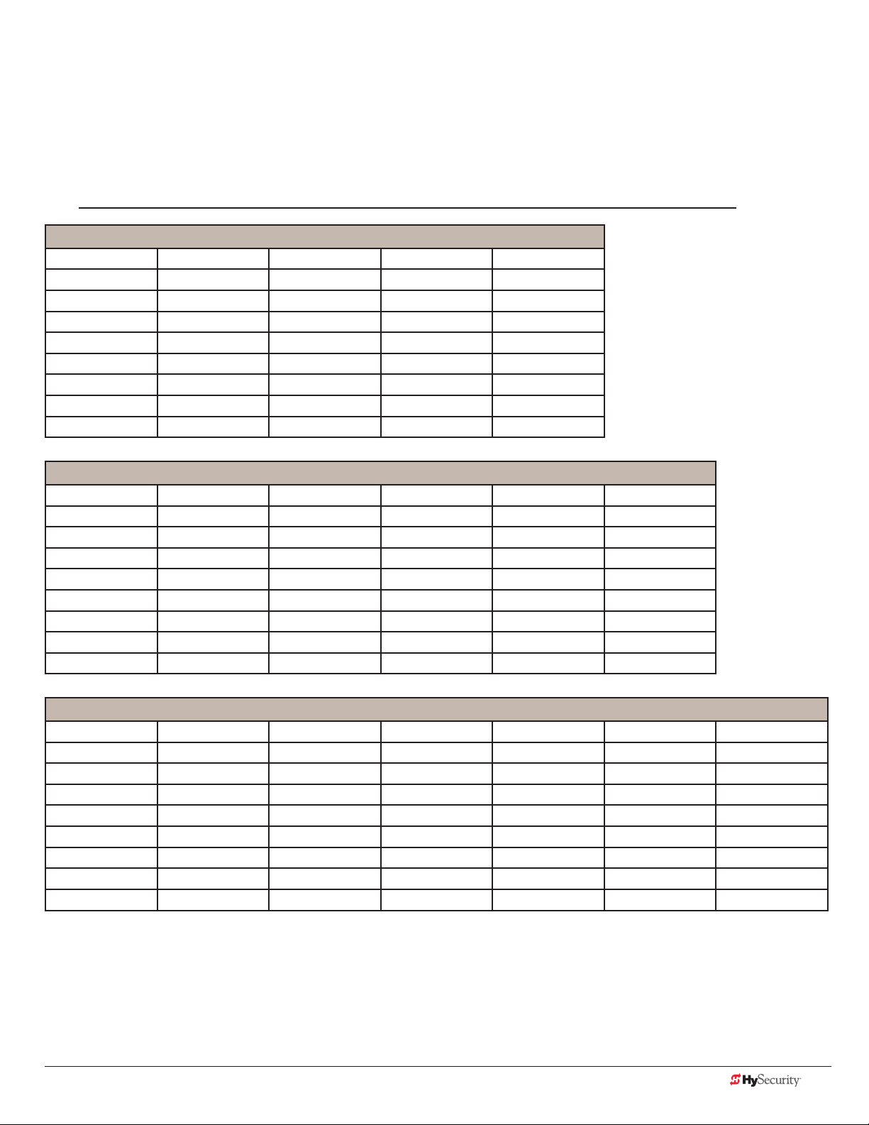
SlideDriver Wiring Charts (Incoming Power)
The maximum distance shown is from the operator to the power source, assuming that source power is from a
panel box with adequate capacity to support the addition of this motor load. The values are for one operator,
with no other loads applied to the branch circuit. Avoid placing more than one operator to a circuit, but if you
must, be certain to reduce the maximum allowed wire distance by half.
NOTE: Distance shown in U.S. Standard “feet.” Metric equivalent shown in parentheses.
SlideDriver Wire Size Chart – 115V Single Phase
Horsepower ½ ¾ 1 2
Amps 10 11.6 14.4 27.2
Wire Gauge Distance Distance Distance Distance
12 90 (27m) 75 (23m) 60 (18m) 30 (9m)
10 140 (43m) 120 (37m) 100 (30m) 50 (15m)
8 220 (67m) 190 (58m) 155 (47m) 80 (24m)
6 350 (107m) 300 (91m) 245 (75m) 130 (40m)
4 555 (169m) 480 (146m) 385 (117m) 205 (62m)
2 890 (271m) 765 (233m) 620 (189m) 330 (101m)
SlideDriver Wire Size Chart – 208V Single Phase
Horsepower ½ ¾ 1 2 3
Amps 5.5 6.1 7.6 14.2 16.2
Wire Gauge Distance Distance Distance Distance Distance
12 290 (88m) 260 (79m) 205 (62m) 110 (33m) 100 (30m)
10 460 (140m) 415 (126m) 330 (101m) 175 (53m) 155 (47m)
8 725 (221m) 650 (198m) 525 (160m) 280 (85m) 245 (74m)
6 1150 (350m) 1040 (317m) 835 (254m) 445 (135m) 390 (119m)
4 1825 (556m) 1645 (501m) 1320 (402m) 710 (216m) 620 (189m)
2 2920 (890m) 2630 (801m) 2110 (643m) 1130 (344m) 1000 (305m)
SlideDriver Wire Size Chart – 230V Single Phase
Horsepower ½ ¾ 1 2 3 5
Amps 5.0 5.8 7.2 13.6 14.8 27.0
Wire Gauge Distance Distance Distance Distance Distance Distance
12 350 (107m) 300 (91m) 245 (75m) 130 (40m) 120 (37m) 65 (20m)
10 560 (171m) 480 (146m) 385 (117m) 205 (62m) 190 (58m) 105 (32m)
8 880 (268m) 760 (232m) 610 (186m) 325 (99m) 300 (91m) 165 (50m)
6 1400 (427m) 1120 (341m) 975 (297m) 515 (157m) 475 (145m) 260 (79m)
4 2220 (670m) 1915 (584m) 1550 (472m) 815 (248m) 750 (229m) 410 (125m)
2 3550 (1082m) 3080 (939m) 2465 (751m) 1305 (398m) 1200 (366m) 650 (198m)
www.hysecurity.com Power D0559 Rev. A 17
Page 26
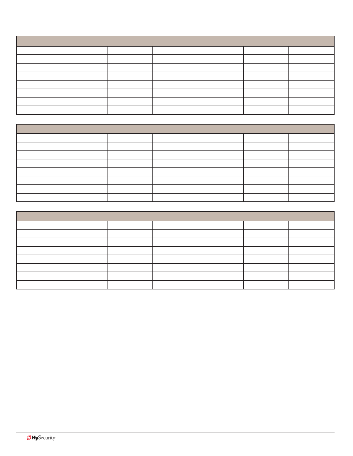
NOTE: Distance shown in U.S. Standard “feet.” Metric equivalent shown in parentheses.
SlideDriver Wire Size Chart – 208V Three Phase
Horsepower ½ ¾ 1 2 3 5
Amps 2.7 3.1 4.2 6.5 6.7 16
Wire Gauge Distance Distance Distance Distance Distance Distance
12 590 (180m) 510 (155m) 375 (114m) 245 (75m) 235 (72m) 100 (30m)
10 930 (283m) 810 (247m) 600 (183m) 390 (119m) 575 (175m) 160 (49m)
8 1475 (449m) 1285 (392m) 950 (289m) 615 (187m) 595 (181m) 250 (76m)
6 2350 (716m) 2045 (623m) 1510 (460m) 975 (297m) 945 (288m) 400 (122m)
4 3720 (1134m) 3240 (987m) 2390 (728m) 1545 (471m) 1500 (457m) 630 (192m)
SlideDriver Wire Size Chart – 230V Three Phase
Horsepower ½ ¾ 1 2 3 5
Amps 2.4 3.0 3.8 6.2 6.4 15.4
Wire Gauge Distance Distance Distance Distance Distance Distance
12 730 (222m) 585 (178m) 460 (140m) 280 (85m) 270 (82m) 115 (35m)
10 1160 (353m) 930 (283m) 730 (222m) 450 (137m) 435 (133m) 180 (55m)
8 1835 (559m) 1470 (448m) 1160 (353m) 710 (216m) 690 (210m) 285 (87m)
6 2925 (891m) 2340 (713m) 1845 (562m) 1130 (344m) 1095 (334m) 455 (139m)
4 4625 (1410m) 3700 (1128m) 2920 (890m) 1790 (546m) 1735 (529m) 720 (219m)
SlideDriver Wire Size Chart – 460V Three Phase
Horsepower ½ ¾ 1 2 3 5
Amps 1.2 1.5 1.9 3.1 3.2 7.7
Wire Gauge Distance Distance Distance Distance Distance Distance
12 2915 (888m) 2350 (716m) 1850 (564m) 1130 (344m) 1100 (335m) 455 (139m)
10 4640 (1414m) 3710 (1131m) 2930 (893m) 1800 (549m) 1740 (530m) 725 (221m)
8 7340 (2237m) 5870 (1789m) 4650 (1417m) 2840 (866m) 2750 (838m) 1150 (350m)
6 11700 (3566m) 9350 (2850m) 7400 (2255m) 4550 (1387m) 4400 (1341m) 1800 (549m)
4 18500 (5639m) 14800 (4511m) 11700 (3566m) 7200 (2194m) 7000 (2134m) 2900 (884m)
18 D0559 Rev. A SlideDriver/SlideDriver 50VF Series www.hysecurity.com
Page 27
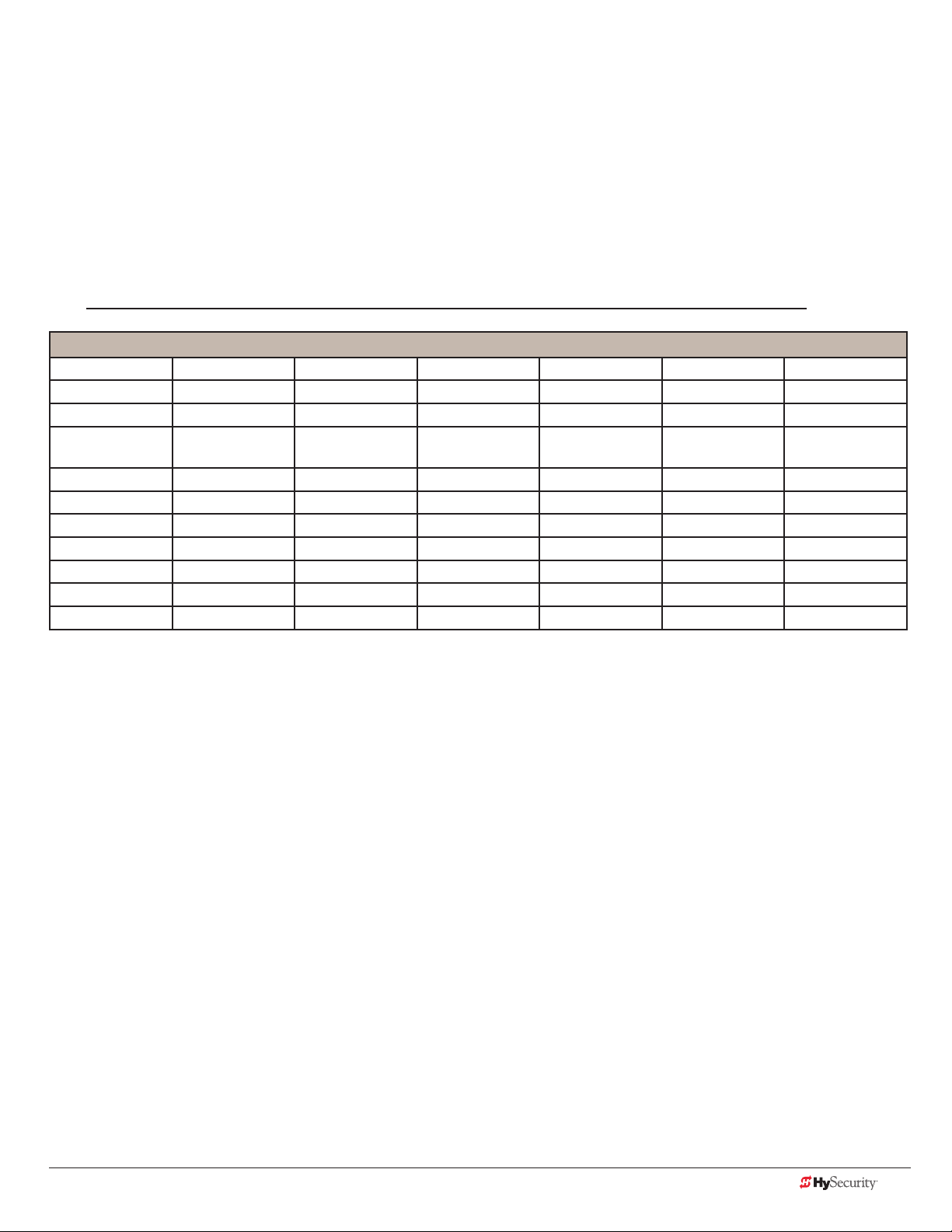
SlideDriver 50VF-series Wiring Chart (Incoming Power)
The maximum distance shown is from the operator to the power source, assuming that source power is from a
panel box with adequate capacity to support the addition of this motor load. The values are for one operator,
with no other loads applied to the branch circuit. Avoid placing more than one operator to a circuit, but if you
must, be certain to reduce the maximum allowed wire distance by half.
Make sure proper wiring is being used. The following table shows the maximum allowable wire run from the
power source to the operator for various wire sizes. Performance of 50VF-series operators on 1Ø and 3Ø
50 or 60 Hz Power.
NOTE: Distance shown in U.S. Standard “feet.” Metric equivalent shown in parentheses.
SlideDriver 50VF-series Wire Size Chart
Phase Ø 1 1 3 3 3 3
Voltage 208 230 208 230 380 460
Horsepower 2 2 2 2 2 2
VFD Rating
Amps
Wire Gauge Distance Distance Distance Distance Distance Distance
12 90 (27m) 100 (30m) 220 (67m) 240 (73m) 680 (207m) 830 (253m)
10 150 (46m) 170 (52m) 350 (107m) 390 (119m) 1090 (332m) 1310 (399m)
8 240 (73m) 270 (82m) 560 (171m) 620 (189m) 1730 (527m) 2100 (640m)
6 390 (119m) 430 (131m) 900 (274m) 990 (302m) 2750 (838m) 3330 (1015m)
4 620 (189m) 680 (207m) 1430 (436m) 1580 (482m) 4380 (1335m) 5300 (1615m)
2 990 (302m) 1090 (332m) 2280 (695m) 2530 (771m) 6990 (2130m) 8470 (2582m)
17.4 17.4 8.7 8.7 5.2 5.2
Performance of 50VF-series Operators on 1 and 3 Phase, 50 or 60Hz
A HySecurity 50VF2, 50VF-EFO, or 50VF3 operator can operate on a wide variety of incoming power.
• 50Hz/60Hz operation with no changes or reconnection
• 1Ø or 3Ø operation by eld rewiring and reconnection
• The incoming voltage must match the operator nameplate. Although the electric motor can be
reconnected, a different VFD (motor controller inside the grey control box) is required between 460V and
208V/230V.
• Any AC powered peripherals such as locks, card readers and other devices need to be checked for
compatibility.
• The electric motors in all VF2 and VF3 operators are 3Ø/60Hz motors and are connected for the voltage
shown on the operator’s nameplate. (208V/230V or 460V)
www.hysecurity.com Power D0559 Rev. A 19
Page 28

How is this done?
WARNING
WARNING
• The VF controller in the operator is rated to operate on input frequencies ranging from 48Hz through
62Hz on 1Ø or 3Ø power (a jumper connection is required for phase change) but only on either 460VAC
or 208V/230V. (A change between 460V and 230V, either direction, requires replacing the VF controller).
• The control transformer in the operator is tapped for multiple voltages and rated for 50/60Hz operation.
• The VF controller rst recties and lters the incoming power to DC, which has no frequency or phase. It
then creates 3Ø variable voltage/variable frequency AC for the motor from the DC.
• Depending on the model, the VF controller ramps the motor voltage and frequency from 0V@0Hz at
start, to either 208/230 or 480 VAC @ 60Hz for full speed. This allows use of 60Hz motors regardless of the
incoming frequency.
• Since the input voltage/frequency is converted to DC to begin with, there is absolutely no relationship
between the input frequency/phase and frequency/phase of the power supplied to the motor. The input
could be 1Ø or 3Ø, 48Hz or 62Hz and the controller/motor combination wouldn’t care. It will create the
ramped 3Ø voltage and frequency for which it is programmed.
NOTE: SlideDriver 50VF operators connected for 1Ø operation will draw more current because the utility power
to run the machine will be carried to the operator on two wires instead of the three used for 3Ø operators. Be
sure to allow for this difference when specifying wire size.
In-Field Connections
SlideDriver 50VF-series operators are eld re-connectable for 1Ø or 3Ø, 208/230VAC input power without
changing the VFD.
SlideDriver 50VF-series operators CANNOT be connected to 120V, 1Ø power or 575V, 3Ø power. If any attempts
are made to do so, serious injury, electrical shock, or death may result. Any electrical damage occurring to the
operator will not be covered by the Limited Warranty.
SlideDriver 50VF-series operators are NOT eld recongurable between 208/230VAC and 480VAC power. The
VFD Motor Controller in a 208/230VAC unit must be replaced with a VFD Motor Controller manufactured for the
higher (480VAC) voltage input.
20 D0559 Rev. A SlideDriver/SlideDriver 50VF Series www.hysecurity.com
Page 29
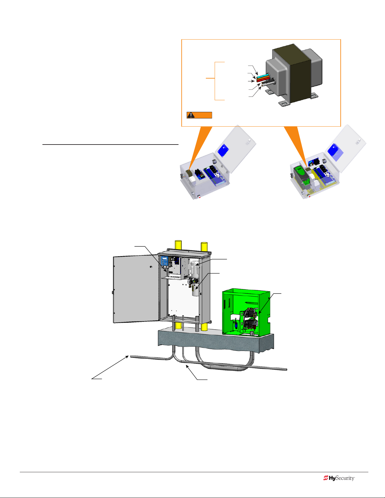
Control transformer ConneCtIons (non-ups)
WARNING
Connect the AC input power to the control
transformer according to the following procedure.
1. Ensure that the primary tap on the control
transformer matches the line voltage and
frequency connected to the gate operator.
2. Measure the line voltage carefully to
distinguish between 208V and 230V branch
circuits.
NOTE: A label on the transformer top identies the
various voltage taps available.
3. Use wire nuts or crimp-connectors to
connect the power input conductors to the
applicable taps on the Control Transformer.
Input taps
connection wires match the voltage found on the operator’s nameplate.
Blue - 480 VAC
Orange - 240 VAC
Red - 208 VAC
Black - Common
White - 120 VAC*
* Variable Frequency (VF) or 2 hp gate operators:
Never connect to the white 120V wire. Make sure the
All (Excluding SD50VF) SD50VF - series
Control Transformer
gate operator ConneCtIons (modular unIt)
Control box with display
Electric motor
Hydraulic pump pack
Hydraulic motors,
Drive dheels,
Limit switches,
Toggle handle release
High voltage electrical power
input wiring
Vehicle detector & control
signal input wiring
If you have the modular unit, additional conduit is needed to house the hydraulic hoses and electrical wiring.
You need a 2-inch (5 cm) diameter conduit for hydraulic hoses and a ¾-inch (19 mm) conduit for electrical wiring.
AC input power is connected to the hydraulic pump and electrical components enclosure (HydraSupply).
A supplemental manual, provided with the product, describes the installation overview, wiring and conduit
considerations.
www.hysecurity.com Power D0559 Rev. A 21
Page 30

dC power supplY (ups) ConneCtIons
If you have a gate operator with a DC Power Supply unit, you will need to
connect the primary AC input power to the DC Power Supply.
DC Power
Supply
Cabinet
Additional ¾-inch (19 mm) conduit is needed for electrical wiring
interconnections between the gate operator and DC Power Supply
Cabinet. AC input power is connected to the electrical components in
the chassis, and additional wiring is run through conduit to the DC Power
Supply Cabinet.
Conduit
A supplemental manual (D0598), provided with the DC Power Supply
Cabinet, describes the installation overview, wiring and conduit
considerations.
22 D0559 Rev. A SlideDriver/SlideDriver 50VF Series www.hysecurity.com
Page 31

Configure the Operator
When you rst apply power to the operator, it is locked in Menu mode
and prompts appear on the display. The gate will not move and the
controls will not function until the prompts have been answered. The
prompts include:
• Usage Class setting
• Gate handing
NOTICE: Before turning the power switch to ON, make sure all site requirements
concerning proper wiring, safety, foundation installation, and electrical power
have been met.
Five buttons on the display keypad provide operational controls. Refer
to Initial Setup on page 35 for more information. To answer the initial
prompts, use the Previous, Next, and Select buttons as described in the
chart below:
Smart Touch Controller: Menu Mode Navigation Buttons
UC 2
USAGE CLASS
To change that data appearing
in the display
Press Select.
Two left characters blink.
To navigate through the
Selections
Press Next.
Continue pressing Next to view
all selections. (Press Previous to
reverse direction.)
To choose what appears on
the display
Press Select.
Blinking characters
become static.
To navigate between menu
items
Press Next or Previous.
Advance - press Next
Previous - press Previous
If you are unsure of the usage classication, refer to Identifying Gate Operator Category and Usage Class on
page 7. It explains the different usage site classications for UL 325.
gate HandIng
The handing is determined by the position of the operator and which way the gate opens.
To determine handing, face the front cover panel on the operator. Refer to the illustration below.
OPEN OPEN
Left-Hand
Gate
www.hysecurity.com Congure the Operator D0559 Rev. A 23
Right-Hand
Gate
Page 32

HYdraulIC Hose swap
CAUTION
SH L
GATE HANDING
Gate Handing is determined by viewing the gate opening from the secure side. If the gate opens to the left, the
gate must be set for left handing.
All SlideDrivers are set at the factory for right handing. If the gate has left handing, you must
• select SH L when prompted (or access the
• swap position of the hydraulic hoses.
Installer Menu)
adjustIng tHe pressure relIef valve
Factory set for right-handing.
Swap hose connections for
left-handing gate.
When placing the operator into service, pressure relief valve
adjustments are required! To provide instruction during
installation, a cautionary yellow tag is wire tied to every pump
pack. The same instructions are provided in this section.
Pressure relief valves differ depending on the model.
Tools Needed: 5/32 " hex key, ½" and 9/16 " box end wrenches.
NOTICE: Pressure relief valve adjustments establish the threshold for the inherent entrapment sensor (IES). The
optimal pressure setting produces uniform gate travel and trips the IES when the gate encounters an obstruction.
Model Motor hp Maximum PSI
SlideDriver 15, 40 1 hp 1000 psi
SlideDriver 30F, 80, 50VF 2 hp 1350 psi
SlideDriver 200 5 hp 2000 psi
Never exceed the maximum psi setting.
24 D0559 Rev. A SlideDriver/SlideDriver 50VF Series www.hysecurity.com
Page 33

Adjustment Screw
DANGER
SlideDriver 30F, 80, 200
Pressure
Gauge
The Pressure Relief
Valve is located
behind the motor
on the pump rack or
soft start manifold.
Motor
Pump
pack
Adjustment Screw
SlideDriver 15, 40, 50VF
Make sure the gate is properly installed and aligned before performing the following steps. Take precautionary
measures to keep the gate’s travel path clear. The gate will be moving while you adjust the pressure relief valve.
DO NOT attempt to adjust the pressure relief valve unless you are an experienced hydraulic gate
operator installer. Incorrect pressure settings can cause injury and even death!
1. Expose several threads on the Pressure Relief Valve by loosening the locknut with a 9/1 6" box end wrench.
2. Depending on the model, insert a 5/3 2" hex key or use a ½" box end wrench to turn the Adjustment Screw.
3. Use the keypad to cycle the gate open or close and, while the motor is running, turn the Adjustment
Screw clockwise (CW) to raise the pressure. The motor runs for a few seconds, stops, and then enters safe
mode. SAFE appears on the display.
4. Press RESET and repeat step 3 until gate travel is reliably consistent without entering SAFE mode.
5. To lock in the pressure setting, hold the Adjustment Screw with a hex key or wrench and tighten the
locknut.
www.hysecurity.com Congure the Operator D0559 Rev. A 25
Page 34

tHe InHerent entrapment sensor (Ies)
The IES on HySecurity hydraulic operators is a primary entrapment device that is required by UL 325 as a type “A”
detection device. It is tripped through software programming OR hydraulic pressure settings. It does not function
solely on its own accord and must be connected to the Smart Touch Controller. The sensitivity and response of
the IES when tripped is factory set, but can be adjusted through the Installer Menu items:
• SE (Inherent Sensor sensitivity)
• SS (Inherent Sensor function)
• SR (IES reverse to open)
Smart Touch Controller™ – Installer Menu Functions for IES
Installer Menu
Display Code
SE 2
IES SENSITIVITY
1 = max. sensitivity
2 = Default setting
9 = least sensitivity
Setting Options
(Bold – Factory Settings)
Description
Adjusts the sensitivity of the internal inherent entrapment sensor (IES).
Available settings are 1 to 9 with 9 being the least sensitive. HySecurity
strongly recommends that you avoid setting the IES sensitivity higher
than 6.
Note: Adjust pressure relief valve on hydraulic operators for security
and gate impact purposes prior to changing IES sensitivity. Refer to
the operator’s manual for steps involved in adjusting the pressure relief
valve setting.
SS 0 (OFF)
IES STOP ONLY
SR 0 (FULL OPEN)
REVERSAL LOGIC
0 = stop, reverse for 2s
1 = stop only
0 = IES reverses full open
1 = 2 second reversal only
In a Usage Class IV environment, the operator can be set to stop the
gate and not reverse gate travel after and IES trip.
The default setting is a 2-second duration reversal if the inherent sensor
is triggered. The optional setting of 0 will cause the gate to reopen fully
if triggered while closing.
Manufacturer’s responsibility
• Build into the gate operator a means of detecting an obstruction or an inherent entrapment detection
device (UL 325 30A.1.1)
• Accept input from external entrapment detection devices
• Provide warning signs and an installation manual which, if followed, will result in a UL 325 compliant
installation
Pressure Relief Valve – All Hydraulic Operators:
• Limits hydraulic system pressure
• By-passes uid to tank when set-point exceeded
• By-passed uid triggers the IES
NOTICE: Pressure relief valve adjustments establish the threshold for the Inherent Entrapment Sensor (IES). The
optimal pressure setting produces uniform gate travel and trips the IES when the gate encounters an obstruction.
26 D0559 Rev. A SlideDriver/SlideDriver 50VF Series www.hysecurity.com
Page 35

Inherent Entrapment Sensor – (IES)
SP 2
SPEED
• Normally closed pressure switch on pump manifold
• Senses uid ow “above” pressure relief valve indicating high pressure and possible gate obstruction
• An open contact during gate movement signals the Smart Touch Controller to put operator into “SAFE”
mode
• Ignored for the rst second of operation to get past starting pressure spike
• An open contact while the gate is not operating will generate Err2 – disconnected IES
• A second open contact, in either direction of travel, will lock the machine out and the “ENTR”, or
entrapment mode, appears on the display
modBus rtu In slIdedrIver 50vf-serIes
In the 50VF series SlideDriver™, a communication protocol allows the Smart Touch
Controller to constantly monitor the Variable Frequency Drive (VFD) and record
events in the STC history log. The history log is easily accessible using the HySecurity
S.T.A.R.T. program and a PC laptop computer.
With the ModBus RTU:
• Reduction in eld calls is likely because the STC resets VFD faults or error
codes upon receiving a new command.
• Quality issues with the site power are controlled better which results in less
intermittent operator problems.
• Smoother operator acceleration and deceleration enhances gate travel.
All 50VF2-3 series SlideDrivers shipped after January 1, 2012 have the new ModBus
cable and RTU communication protocol installed. If you need replacement parts for
your existing 50VF series operators, be sure to have the serial number of the
operator available when you order parts.
If you install a new 50VF2/3 operator, the speed is factory set at 2 foot per second (2 ft/s).
To change the speed, you will need to access the Installer Menu.
• SP 2 sets the 50VF2/3 speed to approximately 2 ft/s.
• SP 3 sets the 50VF2/3 speed to approximately 3 ft/s.
Refer to “Emergency Fast Operate (EFO) in
SlideDriver 50VF-series” on page 28.
• SP 0 and SP 1 are not used. (If you change the setting to 0 or 1, the operator will
not run.)
www.hysecurity.com Congure the Operator D0559 Rev. A 27
Page 36
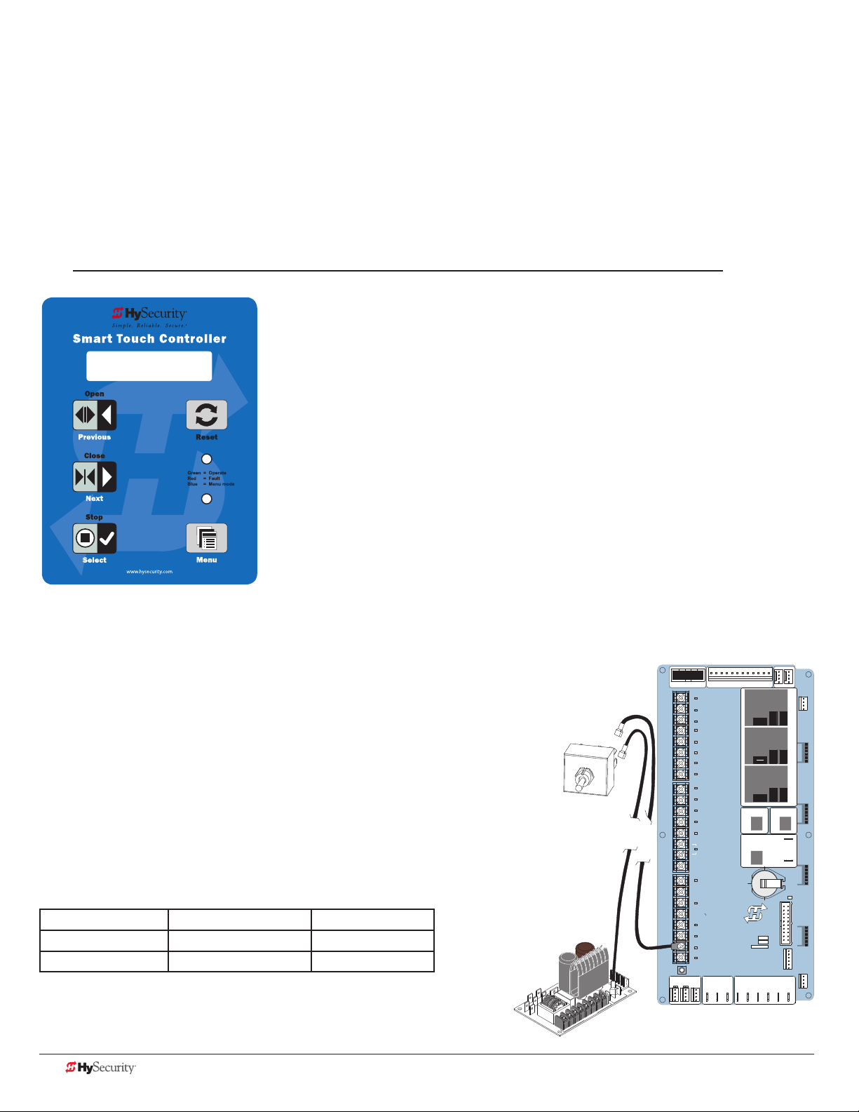
emergenCY fast operate (efo) In
VEHICLE DETECTORVEHICLE DETECTORVEHICLE DETECTOR
VEHICLE DETECTOR
slIdedrIver 50vf-serIes
Setting the Emergency Fast Close
To enable the Emergency Fast Close option on a SlideDriver 50VF-series operator, you need to program the
Smart Touch Controller by taking the following steps:
NOTE: When you are in programming mode the buttons on the keypad change from Open, Close, and
Stop to Previous, Next, and Select. Refer to “Menu Mode Navigation” on page 36.
1. Make sure the operator is turned ON and a Run mode status (example,
GATE OPEN) appears on the Smart Touch Controller, which indicates the
machine is operational.
OC 1
EMERGENCY CLOSE
2. Press the Menu button twice to access the User Menu.
3. Press and hold the Reset button and then the Open button. Hold the
buttons for two seconds and then release both buttons. FO x appears on
the display which indicates you have accessed the Installer Menu.
4. Press Next until the Emergency Close (OC 0)appears on the display.
5. Press Select and OC starts blinking, which indicates the display can be
changed.
6. Press Next or Previous to change the display to OC 1.
7. Press Select to accept the entry. (The display characters stop blinking.)
8. Press Program to exit programming mode and return to Run mode.
A Run mode gate status appears (example, GATE OPEN).
Installing a Push-Button Device for EFC
The Emergency Fast Close on the 50VF-series is designed for a
constant hold function, such as a push-button device that is held
for the duration of gate travel. To operate properly, the device must
be connected to Terminal 23 on the Smart Touch Controller and a
+24VDC terminal on the Power Module.
When the connections are made, a constant hold signal transmitted
to the Smart Touch Controller causes the Emergency Fast Close
function to close the gate at a higher speed than usual, and photo
eyes, vehicle loop inputs, and other safety devices are ignored.
Emergency Fast Close Speeds
Operator Close Speed EFO Close
SlideDriver 50VF2 2.2 fps (26 in per sec) 3 fps (91 cm/s)
SlideDriver 50VF3 3 fps (91 cm/s) 3 fps (91 cm/s)
Power Connector
USER 3
HySecurity
MX000585
VERSION
S/N
RADIO OPTIONS
RS485
STOP/BUZZER
MOTOR USER 1
FREE
EXIT
USER 2
INSIDE
OBSTR
OUTSIDE
OBSTR
COM
NO
STATUS
SHADOW
RESET
DISPLAY
RS232
WIEGAND
COMOPEN EDGE+24V +24V
STOP BUTTON
OPEN BUTTON
CLOSE BUTTON
REMOTE OPEN AND
RADIO CONTROL
OPEN/CLOSE
OPEN PARTIAL
INTERLOCK OPEN
TIME CLOCK OPEN
FREE EXIT DETECTOR
DISABLE EXIT DETECTOR
DISABLE CLOSE TIMER
INSIDE OBSTRUCTION
VEHICLE DETECTOR
OUTSIDE OBSTRUCTION
VEHICLE DETECTOR
SHADOW/RESET
VEHICLE DETECTOR
EDGE SENSOR
PHOTO EYE POWER
24 VOLTS COMMON
PHOTO EYE POWER
DO NOT USE
PHOTO EYE
OPEN DIRECTION
DO NOT USE
PHOTO EYE
CLOSE DIRECTION
DO NOT USE
CHARGER
AC LOSS
LOCK INTERLOCK
EMERG CLOSE
FIRE DEPT OPEN
Smart Touch Controller
RPM
COM COMA B
POWER
DRIVE
1
2
3
4
5
6
7
8
9
Emergency Fast
Close Device
(Actuator)
Power Module
D
V
24
24V
A
C A
cce
s
s
or
y powe
r
+
ON
MM
O
C
10
11
12
14
15
16
17
18
19
20
21
22
23
24
LED
LIMIT DUAL GATE
C
28 D0559 Rev. A SlideDriver/SlideDriver 50VF Series www.hysecurity.com
Page 37

Control Panel Overview
This section provides an overview of the the electrical controls found in your gate operator. The illustrations
highlight the various components and describe their function. Each callout explains where to nd more
information about the component.
SlideDrive Models: All, except 50VF Models
Transformer:
Provides the connections for AC power and steps
down the voltage to 24 VAC. For more information,
refer to Control Transformer Connections (Non-UPS)
on page 21.
Power Module
Provides common and 24VAC & 24VDC terminals.
Refer to Overview of the STC and Power Module
on page 50.
Control Box
Reset Switch
Power Switch
www.hysecurity.com Control Panel Overview D0559 Rev. A 29
Smart Touch Controller:
Provides inputs for peripherals and accessories, 2
electromechnical user relays (250VAC, 10A), one solid
state user relay (30VDC, 3A). For more information, refer
to STC Terminal Inputs on page 52.
Page 38

slIdedrIver wIrIng dIagram, d0266 rev B
WHITE 120
BLUE 480
ORANGE 240
RED 208
EXTERIOR
RESET
DUAL GATE
30 D0559 Rev. A SlideDriver/SlideDriver 50VF Series www.hysecurity.com
Page 39
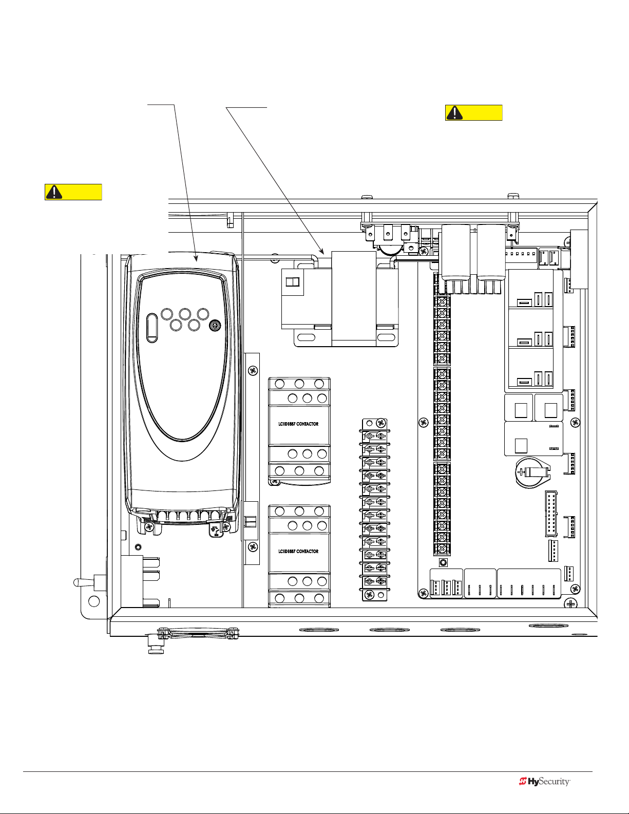
varIaBle speed drIve (vfd) Control Box
SlideDriver 50VF Models
Variable Frequency Drive
(VFD): Controls RPM for smooth
acceleration & deceleration and
connects to the STC through
ModBus communication wires
for diagnostic purposes and
control handling.
CAUTION
Residual voltage remains in the
VFD which can cause electrical
shock to personnel or damage
to the equipment.
Transformer:
Provides the connections for AC
power and steps down the voltage to
24 VAC. For more information, refer
to Control Transformer Connections
(Non-UPS) on page 21.
CAUTION
* On VFD operators, never connect
to the white 120V wire. Make sure the
connection wires match the voltage
label found on the operator’s name
plate.
www.hysecurity.com Control Panel Overview D0559 Rev. A 31
Page 40

varIaBle speed drIve wIrIng dIagram
NOTE: DRAWING IS NOT TO SCALE.
COLOR CODED TRANS. LEAD TO L1
W
G
OW
T
SlideDriver 50VF Models
POWER
SUPPLY
BOARD
24VAC
CONTROL
TRANSFORMER
GREEN -
RED +
+24VAC
BLACK FROM T1 TO COM
BLACK TO B7
BLACK TRANS. LEAD TO L3
3 PH TO ELECTRIC
MOTOR
RED TO B5
GREY TO 24VDC
DRIVE
STOP BUTTON
1
2
OPEN BUTTON
3
CLOSE BUTTON
REMOTE OPEN AND
4
RADIO CONTROL
5
OPEN/CLOSE
OPEN PARTIAL
6
INTERLOCK OPEN
7
TIME CLOCK OPEN
FREE EXIT DETECTOR
8
DISABLE EXIT DETECTOR
9
DISABLE CLOSE TIMER
INSIDE OBSTRUCTION
10
VEHICLE DETECTOR
OUTSIDE OBSTRUCTION
11
VEHICLE DETECTOR
SHADOW/RESET
12
VEHICLE DETECTOR
EDGE SENSOR
14
PHOTO EYE POWER
24 VOLTS COMMON
PHOTO EYE POWER
15
DO NOT USE
16
PHOTO EYE
17
OPEN DIRECTION
DO NOT USE
18
PHOTO EYE
19
CLOSE DIRECTION
20
DO NOT USE
CHARGER
21
AC LOSS
LOCK INTERLOCK
22
EMERG CLOSE
23
FIRE DEPT OPEN
24
LED
Smart Touch Controller
LIMITDUAL GATE
RPM
COMCOMAB
DUAL GATE
POWER
USER 3
HySecurity
MX000585
VERSION
S/N
RADIO OPTIONS
DISPLAY
RS485
STATUS
EXTERIOR
STOP/BUZZER
RESET
MOTORUSER 1
FREE
EXIT
USER 2
BUZZER
INSIDE
OBSTR
OUTSIDE
OBSTR
COM
NO
VEHICLE DETECTORVEHICLE DETECTORVEHICLE DETECTOR
SHADOW
RESET
RS232
RS232
WIEGAND
IE
SERIAL
AND
COMOPEN EDGE+24V +24V
MEMBRANE
KEYPAD
1 PH. USE
ONLY L1 & L3
INTERNAL
OVERLOAD
END OF TRAVEL
DISPLAY
BOARD
LEGEND
1 COMMON
2 MENU
3 RESET
4 OPEN
5 CLOSE
6 STOP
23456
1
LIMITS
DIRECTIONAL
VALVE
SLOW DOWN
LIMITS
IES SENSOR
32 D0559 Rev. A SlideDriver/SlideDriver 50VF Series www.hysecurity.com
Page 41

stC Board, power module and dIsplaY
The Smart Touch Controller provides connections for a multitude of peripherals and accessory devices. The
Power Module offers 8 common bus terminals, 4 terminals (24VAC) and 3 terminals (24VDC) with a 3A maximum
draw. The touch-sensitive keypad and 32-character display connects to the STC with a waterproof ribbon cable.
For more information about STC Inputs and connections, refer to STC Inputs & Wiring on page 49. For more
information about the display programming, operator modes and keypad navigation, refer to Display & Menu
Options on page 35.
Smart Touch Controller:
Provides inputs for peripherals & accessories, 2 electromechnical user relays (250VAC, 10A), one solid state user relay
(30VDC, 3A). For more information, refer to STC Inputs & Wiring
on page 49.
Power Module
C
D
V
24
+
24V
A
C A
cce
s
s
or
y powe
r
ON
MM
O
C
Common (COM) power
terminal strip
STC Display & Keypad:
Provides push button programming and
displays menu codes, faults, alerts & errors.
Refer to Display & Menu Options on page 35.
DRIVE
1
2
3
4
5
6
7
8
9
10
11
12
14
15
16
17
18
19
20
21
22
23
24
LIMIT DUAL GATE
STOP BUTTON
OPEN BUTTON
CLOSE BUTTON
REMOTE OPEN AND
RADIO CONTROL
OPEN/CLOSE
OPEN PARTIAL
INTERLOCK OPEN
TIME CLOCK OPEN
FREE EXIT DETECTOR
DISABLE EXIT DETECTOR
DISABLE CLOSE TIMER
INSIDE OBSTRUCTION
VEHICLE DETECTOR
OUTSIDE OBSTRUCTION
VEHICLE DETECTOR
SHADOW/RESET
VEHICLE DETECTOR
EDGE SENSOR
PHOTO EYE POWER
24 VOLTS COMMON
PHOTO EYE POWER
DO NOT USE
PHOTO EYE
OPEN DIRECTION
DO NOT USE
PHOTO EYE
CLOSE DIRECTION
DO NOT USE
CHARGER
AC LOSS
LOCK INTERLOCK
EMERG CLOSE
FIRE DEPT OPEN
LED
RPM
Power Connector
POWER
USER 3
HySecurity
MX000585
VERSION
S/N
Smart Touch Controller
RADIO OPTIONS
COM COMA B
RS485
STATU S
DISPLAY
RS232
MOTOR USER 1
USER 2
COM
NO
COMOPEN EDGE+24V +24V
EXIT
OBSTR
OBSTR
RESET
STOP/BUZZER
FREE
INSIDE
OUTSIDE
VEHICLE DETECTORVEHICLE DETECTORVEHICLE DETECTOR
SHADOW
VEHICLE DETECTOR
WIEGAND
Smart Touch Controller
Ribbon cable
www.hysecurity.com Control Panel Overview D0559 Rev. A 33
Page 42

34 D0559 Rev. A SlideDriver/SlideDriver 50VF Series www.hysecurity.com
Page 43

Display & Menu Options
HYSECURITY
GATE STOPPED
Highly sophisticated software provides three different modes of operation: run, program, and fault. How to
navigate using the Smart Touch Controller (STC) keypad, interpret status display codes and program the
operator is found in this section.
CAUTION
Keep your operator current with the latest software version. Use of HyNet™ and other accessories requires
software version h4.35 or higher.
InItIal setup
Once you have completed the installation, attached the wired accessories and turned the power ON, you’re
ready to program the operator. Two different approaches exist:
• Connect a laptop computer to the serial (RS-232) port, check for
the most current software version and then set the operator menu
congurations via the START software.
NOTE: Use a laptop computer at your place of business to conveniently
download the free START software and most current software version
from www.hysecurity.com before heading out into the eld. This makes
it easy to adjust settings using a laptop.
• Manually navigate through the User and Installer Menus using the
STC keypad. The instructions for performing this second option are
provided in this section.
understandIng tHe dIsplaY and KeYpad
The STC display and keypad provide access to the operator’s sophisticated
software and functionality.
Three different operational modes exist:
• Run Mode - gate is operational, awaiting commands.
• Program Mode - motor disengages and operator commands are
ignored. Data entry, menu navigation, and menu selection can be
accomplished via the keypad or through a START software connection
using the RS-232 port.
• Fault Mode - alerts, faults, or errors appear on the display. Some errors
or faults can be reset with the Reset button while more serious faults
require additional troubleshooting. Faults indicate a need for diagnosis
and resolution. Refer to Troubleshooting on page 73.
The keypad lets you navigate, change, or clear the information in the display
menus. The singular use of these keys is dependent on the operator mode.The
buttons with text above and below have two functions. Use these buttons to enter
operating commands or navigate through the User and Installer Menus.
www.hysecurity.com Display & Menu Options D0559 Rev. A 35
Gate Status Display
in Run Mode
Page 44
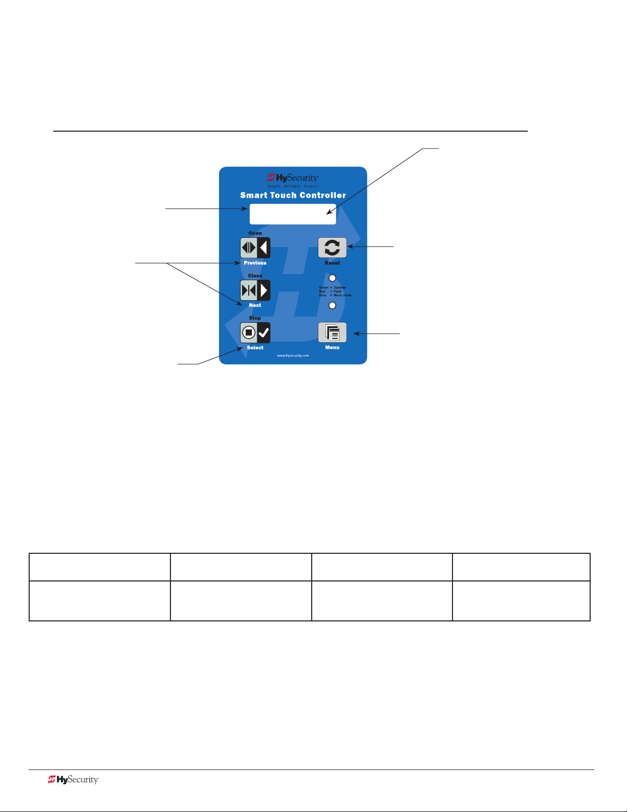
menu mode and tHe stC KeYpad
In Menu Mode, the motor disengages and operator commands are ignored. Data entry, menu navigation, and
menu selection can be accomplished using the buttons on the Smart Touch Controller keypad.
NOTE: Menu Mode automatically returns to Run Mode if no activity (i.e. key presses) occurs for two minutes.
32-character display provides
information about the menu items.
Two blinking characters
indicate that the display
will accept changes.
Next or Previous
Navigational buttons.
Pressing Next or Previous
scrolls through the selections.
CT 0 (OFF)
CLOSE TIMER
The Reset button is disabled while in
Menu Mode.
Pressing Select causes the leftmost two
characters to blink, (CT in the example),
which indicates the display is ready to
accept changes to a menu setting.
Use the navigational buttons to view selections. Press Select a second
time to accept what appears on the display. Entry mode is exited, the
two characters stop blinking, and Next or Previous must be pressed to
move onto a different display. Pressing Menu exits to Run mode.
The Menu button accesses Menu mode.
When the menu item is selected and blinking,
the Menu button has no function. However,
pressing Menu when the 2 characters are
static (not blinking), returns the operator to
Run Mode.
menu mode navIgatIon
Navigating within the program menus is easy once you learn how the keypad buttons function. Refer to the
following chart.
Smart Touch Controller: Menu Mode Navigation Buttons
To change that data
appearing in the display
Press Select.
Two left characters blink.
To navigate through
the Selections
Press Next or Previous.
Continue pressing Next to view
all selections.
To choose what appears
on the display
Press Select.
Blinking characters
become static.
To navigate between
menu items
Press Next or Previous.
Advance - press Next
Previous - press Previous
36 D0559 Rev. A SlideDriver/SlideDriver 50VF Series www.hysecurity.com
Page 45
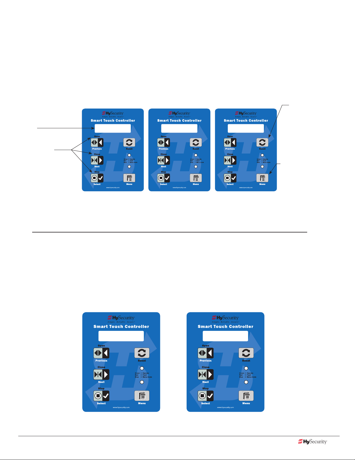
run mode and tHe stC KeYpad
OT 1 OPERATOR
SLIDEDRIVER
UC 2
USAGE CLASS
The Run Mode displays appear static when the operator is ready and waiting for a run command. When the
display is ashing GATE OPENING or GATE CLOSING, a command has been received and the barrier gate is in
motion. The command may come from a variety of sources: a card reader, push-button remote, or recognition of
a vehicle passing over a loop detector. In all cases, the operator “runs” the motor when it receives an operational
command.
Three displays indicate the position or status of the barrier gate. The keypad entry used to access the User or
Installer menus, begins at one of these Run Mode displays.
Pressing Reset clears
32-character display
identies operator
modes.
Pressing Open,
Close, or Stop causes
the gate to perform
the command.
HYSECURITY
GATE OPEN
HYSECURITY
GATE CLOSED
Run Mode Displays
HYSECURITY
GATE STOPPED
alerts or faults and
returns to Run Mode.
NOTE: Press Reset at
any Run mode status
display to view the
software version. For
example: h4.35
Pressing Menu scrolls
through operator status
displays and accesses the
User Menu.
NOTE: Pressing the Menu
button twice, bypasses the
operator status displays.
NOTE: To access the User or Installer menus, the motor cannot be engaged and the gate cannot be moving.
vIewIng operator status dIsplaYs
Press the Menu button once and the operator status displays scroll past in two second intervals. Pertinent
information appears to provide a quick overview of the operator’s status or congurations.
The type of information that may scroll across the display includes: interlocked or sequenced gate (if applicable),
operator type (OT), gate handing, Usage Class (UC), buss voltage, and life cycle counter.
Example of Operator Status Displays
www.hysecurity.com Display & Menu Options D0559 Rev. A 37
Page 46

The following chart describes the scrolling status displays in the SlideDriver or SlideDriver 50VF-series.
Operator Status Display Variables Description
Software Version
A lower case “h” appears in front of the
software version number.
Dual Gate or Sequenced Gate This display only appears when the
Operator Type (OT) OT 1 = SlideDriver
Set Handing (SH) L = Left and R = Right Indicates gate handing.
Usage Class (UC) 1, 2, 3, or 4 Displays the operator’s Usage Class
Battery Voltage This display only appears when a DC
Cycle Count (CC) One cycle equals a full open and close
Close Timer (CT) The rst menu item in the User Menu. Displays the number of seconds before the
The software version and revision number
are hard-coded in the Smart Touch
Controller.
operator is used in interlocked or
sequenced gate systems and indicates the
function of the operator: Cfg 1 or Cfg 2
(Conguration 1/2)
OT 7 = SlideDriver 50VF series
power source is being used. The number
varies depending on the voltage that the
charger is providing.
sequence. Partial cycles are not counted
Displays the software version when you
press Reset or cycle power. You will need
the software version when calling Technical
Support.
Indicates, in an interlocked or dual gate
setting, whether the operator is set to
Primary or Secondary or Conguration 1 or
2 (Sequenced Gate setting). The setting is
assigned in the Installer Menu.
Indicates and identies the operator.
designation per UL 325 standards.
Input voltage (DC Buss voltage) to the STC is
shown.
Displays the number of cycles the gate
operator has incurred. Similar to an odometer,
it resets to zero after 999,999 cycles.
open gate initiates. NOTE: You can also
access the Installer Menu from this display.
Stop the Status Display Scrolling
To stop the operator status display scroll and focus on one item, press Select. Press Select a second time, to
resume the scrolling display.
Change the Display Contrast
While the operator status displays are scrolling, you can change the contrast by pressing Select, and then
pressing the up or down arrow keys. The display’s contrast changes accordingly. To exit, press Select again and
the operator status displays continue to scroll and stop at the User Menu entry item.
NOTE: Since sunlight does not affect readability on the OLED display, changing the display contrast is not
available on SlideDriver models shipped with the 32 character display.
Check Time and Date
An easy way to determine if your operator is set for the correct date and time zone can be accomplished by
taking the following steps:
1. While in Run mode (gate status appears in the display), press and hold the STOP button.
The date appears DD/MM, and then the time HH:MM.
2. If you need to change the time zone, refer to the Set Clock “CL” item in the User Menu. Refer to User
Menu: Table 1 on page 39.
38 D0559 Rev. A SlideDriver/SlideDriver 50VF Series www.hysecurity.com
Page 47

user menu
The User Menu consists of several items which can be modied using the Smart Touch Controller keypad.
Access:
Pressing the Menu button, at one of the static Run Mode displays, causes the operator status displays to scroll
past, stop and display the rst user menu item.
When the CT, Close Timer (or HC, Hold to Close) display appears, it means you have accessed the User Menu.
The Close Timer display is the rst in a cyclical series of User Menu displays.
NOTE: To access the User Menu, the operator must be in Run Mode. To bypass the operator status displays,
press the Menu button a second time.
Use the navigational buttons, Select, Next, and Previous to change or view the
menu functions. Refer to the chart, Smart Touch Controller: Menu Mode Navigation
Buttons on page 36.
Table 1 describes the User Menu items and supplies the factory defaults. (Factory
default settings shown in bold.)
CT 0 (OFF)
CLOSE TIMER
user menu: taBle 1
User Menu Setting Options Menu Tasks & Explanations STC Wire Connections
CT 0 (OFF)
CLOSE TIMER
HC 0 (OFF)
HOLD TO CLOSE
HO (OFF)
HOLD TO OPEN
0 = Timer disabled (OFF)
1 second to 99 seconds
0 = off
1 = on
0 = off
1 = on
The Close Timer assigns how many seconds before
the open gate initiates closure. It provides a security
precaution in case a CLOSE pulse from the Arm
Smart DC controller is missed.
Keep the setting at 0 if a hard-wired, push-button
control device is being used. Refer to HC.
NOTE: When the Hold to Close is set to 1 or more
seconds, the Close Timer display does not appear
and HC 1 becomes the User Menu entry display.
Set to 0 to produce a gate closure when a
momentary signal is transmitted.
Set to 1 if a constant hold to close signal, such as
a push button control, is being used. A setting of
1 also deactivates the automatic close timer and
causes its menu to disappear. The Hold to Close
replaces the Close Timer display as the User Menu
entry display.
NOTE: To comply with UL 325 Type D protection,
set HC to 1. Type D UL 325 compliance means no
automatic closing device, such as a timer, loop
sensor, or similar device shall not be employed.
Similar to Hold to Close, but congures the Open
inputs for a constant-hold function.
0 = Momentary open signal
1 = Constant hold open push button required
To comply with UL 325 Type D protection, you must
set HO to 1.
Not applicable (N/A)
COM
Close
COM
Open
www.hysecurity.com Display & Menu Options D0559 Rev. A 39
Page 48

User Menu Setting Options Menu Tasks & Explanations STC Wire Connections
AP 0
AC LOSS
RO 0 (OFF)
RADIO OPEN/CLOSE
BF 2 (ON 2 SEC)
WARN BEFORE OPER
FA 0 (OFF)
FORCE OPEN ALERT
DA 0 (OFF)
DRIFT CLOS ALERT
PE 0 (OFF)
PHOTO EYE ALIGN
CL 0
SET CLOCK
0 = UPS FAIL OPEN
1 = UPS FAIL CLOSE
2 = AUTO OPEN
3 = NO CLOSE TIMER
0 = off
1 = on
0 = off
1 = warning buzzer on
throughout gate travel
2 = warning buzzer on for 2
seconds of gate travel
3 = warning buzzer on
during gate travel
0 = off
1 = on
0 = off (standard)
1 = on (detailed)
0 = off
1 = on
0 = off
1 = on
This menu item only appears if the operator is DC
powered. The setting congures how the gate
functions when AC power fails. For more information,
refer to the supplement provided with the DC Power
Supply operator.
A setting of zero, congures radio input for open
only. Setting 1 adds the capability for radio input to
close the gate, but only when it is fully open.
Controls the warn-before-operate buzzer and can be
congured three ways:
Set to 0: Buzzer is disabled. The buzzer will still beep
if alerts, faults, errors, or entrapment occur.
Set to 1: Buzzer beeps for 3 seconds before gate
moves and continues through entire length of travel.
Set to 2: Buzzer beeps for 3s before gate moves and
continues for 2s of travel.
Set to 3: Available on barrier operators only.
Buzzer beeps when gate starts to move and
continues throughout gate travel.
Intended for highly secure facilities.
Set to 1, the operator sounds the 3-second “warn
before operate” buzzer alarm and initiates a closure
if the gate is forced open and the closed limit switch
disengages. The motor starts to secure the gate. If
the gate does not fully close within 4s, the motor
turns off and the buzzer sounds for 30 seconds. The
display shows ALERT 1 - FORCED OPEN.
Set to 1, the operator sounds the 3-second “warn
before operate” buzzer algate and initiates an open
command if the gate is forced, or drifts, off the open
limit switch. The motor starts to reopen the gate. The
motor runs for a maximum of 4s and, if the gate is
not fully open at the end of this period, the buzzer
sounds for 10s. The display shows ALERT 2 - DRIFT
CLOSED.
Set to 1, the operator serves as an aide in photo
eye transmitter/receiver alignment. The buzzer
chirps once when the emitter and receiver are not
aligned. When the emitter and receiver are aligned,
the buzzer chirps twice. If they go out of alignment
again, the buzzer will chirp once. The Alignment
Mode is reset with a close-limit input or by pressing
the Reset button.
NOTE: If the operator doesn’t run when the power
switch is initially turned ON, check the alignment of
the photo eye and all the photo eye connections.
To adjust the hour, minute, day, or month to a
different time zone, select 1. Once the clock is set,
the display returns to the 0 setting. It is important
to adjust the clock for the operator’s time zone,
because signicant events are time and date
stamped which provides historical operation data
retrievable through S.T.A.R.T. and a PC laptop.
COM
Terminal #21
UPS Terminal strip 24
VDC to control box power
disconnect switch - and +
COM
RADIO Open
Not applicable (N/A)
N/A
N/A
EYE Open
EYE Close
EYE COM
N/A
40 D0559 Rev. A SlideDriver/SlideDriver 50VF Series www.hysecurity.com
Page 49
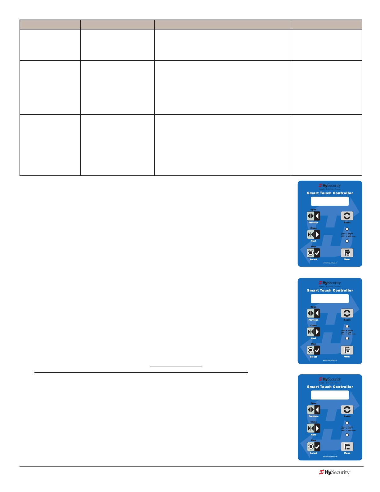
User Menu Setting Options Menu Tasks & Explanations STC Wire Connections
LD 5
LCD CONTRAST
DS 0 (OFF)
DIAGNOSTIC LOGS
PD 0
SET PASSWORD
5
0 through 9
0 = off (standard)
1 = on (detailed)
0 = Off
1 = On (Set Password)
Adjusts the contrast of the display. Available settings
from low contrast 0 to 9 high contrast, with a factory
default setting of 5. NOTE: Not used or available
with the OLED 32 character display.
Set to 0, the STC logs pertinent operator events
such as faults, errors, or menu manipulation. When
experiencing intermittent problems, set this item to
1 to record all operator open and close events, in
addition to the normal alert, fault and error logs. This
parameter automatically resets to the default 0 (off)
after 24 hours.
NOTE: A System Address (SA) value in the installer
Menu must be set before the Set Password display
appears in the User Menu.
To enter a password (up to 80 characters) for
network connectivity, select 1. You can use the menu
navigation buttons to enter the password (SELECT,
NEXT, SELECT). When the password is set, the
display returns to the 0 setting.
N/A
To read the log le, an
RS-232 cable and PC
laptop computer loaded
with HySecurity free
S.T.A.R.T. software is
required. Visit
www.hysecurity.com
Network: Ethernet or
RS-485
Installer menu
HYSECURITY
The Installer Menu options provide more advanced congurations for the gate
operators. Access to the Installer Menu is through the User Menu. The navigational
buttons are the same in both menu modes. Refer to Menu Mode Navigation on
page 36.
GATE STOPPED
Access:
While a static gate status is being displayed, press the Menu button twice. (Bypasses the
operator status displays.)
When the Close Timer display appears (Hold to Close, if the Close Timer display is
hidden):
1. Access the Installer Menu by simultaneously pressing and holding the Reset
and Open buttons.
2. Release both buttons and the display changes, indicating you have arrived at the
rst item in the Installer Menu.
NOTE: Installer Menu options can also be congured through the use of a laptop
computer and S.T.A.R.T. software. See Smart Touch Analyze and Retrieve Tool
information found on the Hysecurity website: www.hysecurity.com
CT 0 (OFF)
CLOSE TIMER
UC 2
USAGE CLASS
www.hysecurity.com Display & Menu Options D0559 Rev. A 41
Page 50

Table 2 describes the Installer Menu items and supplies the factory defaults. (Factory settings shown in bold.)
Installer menu: taBle 2
Installer Menu Setting Options Menu Tasks & Explanations STC Wire
Connections
OT 0
<model name>
AD 0
AC/DC GATE
SP 0
SET SPEED
(or indicate Modbus
control)
UC 0
USAGE CLASS
SH 0
GATE HANDING
BU 0
LOUDEST BUZZER
FD 0 (OFF)
FACTORY DEFAULTS
0 = Operator Type
1 = SlideDriver (HSG) all models
except 50VF series
2 = SwingRiser (HRG)
3 = HydraLift (HVG)
4 = StrongArm (HTG)
5 = SlideWinder 24
6 = SlideWinder 38
7 = SlideDriver 50VF
8 = StrongArm CRASH
9 = HydraSwing
0 = gate disabled
1 = AC (alternating current)
2 = DC battery-power (OT 1-4, 7&8)
0 = gate disabled
1 = No ModBus communication**
2 = 2 ft/s
3 = 3 ft/s
**NOTE: A setting of 1 indicates no
ModBus communication or wiring
is present. The VFD uses its factory
settings to control speed.
0 = gate disabled
1 = single family dwelling
2 = multi-family
3 = industrial *
4 = guarded location *
*not serving the general public
0 = gate disabled
R = viewed from the secure side, the
gate moves right to open
L = viewed from the secure side, the
gate moves left to open
0 = buzzer not set
1 = Frequency 1 * (on)
2 = Frequency 2 * (on)
*Select the loudest buzzer
0 = user settings (custom)
1 = reload factory settings
Select the appropriate number for the operator.
NOTE: This menu item only appears if the Smart
Touch Controller is being replaced.
CAUTION: If you are replacing an
STC board, remember to transfer the
operator’s menu settings from the
existing board to the replacement board.
Refer to the installation instructions that
accompany the replacement STC board.
Select the type of power that the operator uses
and is appropriately wired.
NOTE: This menu item only appears when you
set the OT (operator type).
Set the maximum speed for the gate.
NOTE: This menu item only appears if the SlideDriver operator is part of the 50VF series. It does
not appear with any other operator type.
CAUTION: Standard and Stop extended
limit ramps must be installed on the drive
rails!
Designates the UL 325 Usage Class (UC). The
installer sets the usage class for the operator to
function.
NOTE: The usage class setting does not appear
on Crash products.
Handing only appears on slide gate operators
(OT 1, 5 – 7). On slide gates, the installer sets
the operator’s handing before the operator will
function, so an R or L appears in the display.
This menu item only appears if the operator type
selected is 1 through 4.
Choose the loudest buzzer. The operator
provides an audible beep when you select either
buzzer 1 or 2. Make sure to choose the loudest
audible buzzer sound for your operator type.
Select setting 1 to return the operator to factory
defaults. Globally restores all menu settings back
to new operator status.
NOTE: If factory defaults are restored, any
customized menu settings will need to be
reprogrammed. You can save your customized
menu settings using a PC laptop & S.T.A.R.T.
Not applicable (N/A)
N/A
N/A
N/A
N/A
N/A
N/A
42 D0559 Rev. A SlideDriver/SlideDriver 50VF Series www.hysecurity.com
Page 51

Installer Menu Setting Options Menu Tasks & Explanations STC Wire
Connections
DG 0 (OFF)
DUAL GATE
SG 0 (OFF)
SEQUENCED GATE
CH 0 (AC)
CHARGER TYPE
FO 0 (DISABLED)
FIRE DEPT OPEN
OC 0 (DISABLED)
EMERGENCY CLOSE
SE 2
IES SENSITIVITY
SS 0
IES STOP ONLY
LC 0
LEAF DELAY CLOSE
LO 0
LEAF DELAY OPEN
RT 0 (60 SECS)
MAXIMUM RUN TIME
PO 0 (OFF)
PARTIAL OPEN
0 = solo operator (off)
1 = Secondary unit
2 = Primary unit
3 = Sally Port A
4 = Sally Port B
0 = off
1 = Loop Layout/Site #1
2 = Loop Layout/Site #2
0 = AC powered charger
1 = Solar powered charger
0 = disabled
1 = enabled
0 = disabled
1 = enabled
1 = maximum sensitivity
2 = moderate (default)
9 = lowest sensitivity
0 = (off) Stop and reverse for
2 seconds
1 = (on) stop only (NOTE: Functions
in usage class IV only)
0 = none
1 to 7 = ½ (minimum) to 3½
seconds (maximum) in ½-second
steps (for Primary/Secondary only)
0 = none
1 to 7 = 1/2 (minimum) to 3 1/2
seconds (maximum) in 1/2 -second
steps (for Primary/Secondary only)
0 = 60 Seconds max run
1 = 300 Seconds max run
0 = none
7 to 99 seconds
Establishes communication after wiring dual gate
connections between two operators in Primary/
Secondary or Sally Port site congurations.
This menu item appears if the sequenced gate
menu item (SG) is set at 0 (off).
Establishes communication after wiring two or
more operators as sequential gates.
This menu item only appears if the Dual Gate
menu item (DG) is set at 0 (solo operator).
NOTE: Access the User Menu in both operators
and set a Close Timer.
Does not appear on an AC-powered operator.
The menu item only appears when using the DC
Charger unit and designates the charger type.
Provides the Fire Dept. Open input. When set
to 1, the open signal received by the operator
overrides all photoelectric eyes and edge
sensors, and opens the gate. Pressing the Reset,
Open, or Reset button is required before the
gate can be closed.
Enables the Emergency Close input. When set
to 1, the constant hold close overrides vehicle
detectors, photo eyes and edge sensors, and
closes the gate. Pressing the Reset button once
or the Open button twice is required before the
gate will open.
Adjusts the sensitivity of the internal inherent
sensor. Available settings are 1-9 with 9 being
the least sensitive.
Only available in Usage Class IV gate operators
and allows an option whereby the inherent
sensor will only stop the gate.
Only appears if the gate operator is set up as
a Primary or a Secondary. Available settings
are 1-7. Each increment adds ½ second, to a
maximum of 3 ½ seconds time delay, before the
operator activates when commanded to close.
Only appears if the gate operator is set up as
a Primary or a Secondary. Available settings
are 1-7. Each increment adds 1/2 second (with a
maximum of 3 1/2 seconds) time delay following
a command to open before the operator
activates.
Allows an optional setting of 300 seconds
if changed to [RT 1] as opposed to the
maximum run timer default setting of
60 seconds.
Activates the partial open input and allows an
adjustable distance by setting the open duration.
The available time settings are 7-99 seconds.
The default setting [PO 0] leaves this input
inactive.
Dual Gate COM
(Gate 1) to Dual Gate
COM (Gate 2)
A to A
B to B
Connect Dual Gate
COM (Trafc Gate) to
Dual Gate COM
(Security Gate)
A to A
B to B
+24V
Fire Dept Open (#24)
+24V
EMERG CLOSE (#23)
www.hysecurity.com Display & Menu Options D0559 Rev. A 43
Page 52

Installer Menu Setting Options Menu Tasks & Explanations STC Wire
Connections
EC 0 STOP ONLY
EYE CLOSE LOGIC
0 = Close eye stops only
1 = Reverse to full open with barrier
gates (2 second reverse to open on
swing, slide, or vertical gates)
The default setting is non-reversal if the close
photo eye is triggered. A setting of 1 causes the
gate to reverse and travel full open if triggered
while closing.
EYE Close #19
EYE COM
(Inputs #14 or #15)
EO 0 STOP ONLY
EYE OPEN LOGIC
GR 0 FULL OPEN
GATE EDGE LOGIC
SR 1 REVERSE 25
REVERSAL LOGIC
PC 0 N.O. INPUT
PHOTO EYE OUTPUT
GC 0 N.O. INPUT
GATE EDGE OUTPUT
0 = Open eye stops only
1 = 2 second reverse to close
0 = Edge reverses fully open
1 = 2 second reversal only
0 = IES reverses fully open
1 = 2 second reversal only
0 = Normal Open N.O. INPUT
1 = Normal Closed N.C. INPUT
(monitored)
0 = Normally Open N.O. INPUT
1 = Normally Closed N.C. INPUT
(monitored)
The default setting is non-reversal if the open
photo eye is triggered. The optional setting of
[EO 1] will cause the gate to reverse to close for
two seconds if triggered while opening.
The default setting is reopen fully if the gate
edge is triggered. The optional setting of [GR_1]
sets the gate to a 2-second reversal if triggered
while closing.
The default setting is a 2-second duration
reversal if the inherent sensor is triggered. The
optional setting of [SR_0] will cause the gate to
reopen fully if triggered while closing.
The default setting is for photo eyes with
Normally Close outputs for Crash Operators only.
When set for NC, the connection is monitored
and any open or short circuit fault will generate a
FAL 2 alert which requires a Stop or Reset button
press to clear and enter. All other HySecurity
operators are factory set for normal open (a
setting of zero).
The default setting is edge sensor with Normally
Open (NO) output. The optional setting of 1
requires an (NC) output.
EYE Close
EYE COM
4 wires total:
COM/+24
COM/ PHOTO EYE
CLOSE (#19)
EDGE SENSOR (#13)
COM
TC 1 (INTLOCK)
TIME CLK/INTLOCK
DT 0 FREE EXIT
DISABLE FUNCTION
OR 1 REVERSE
OUTSIDE OBS LOOP
0 = TIME CLK (Select Time Clock)
1 = INTLOCK
Interlock)
0 = Disable Free Exit
1 = Disable Close Timer
0 = Pause closing only
1 = Enable reversing to open
2 = Ignore and continue closing*
(Select Open
Congures the input at Terminal No. 7 on the
STC to be either for the gate interlock function,
or for an external time clock to open input. The
default setting is (TC_1) for the interlock function.
Congures Terminal #9 input to disable either
the Free Exit Detector function or, alternately,
the Timer Close function. The default setting
disables the free exit detector.
NOTE: When set to 0, the free exit is disabled
while gate rests on closed limit. If the closed limit
is not tripped, the free exit continues to work
normally.
The default (1) is for full reversal when the
Outside Obstruction Loop is triggered. A
setting of 0 causes the gate to only pause when
triggered. The gate closure begins as soon as
the loop is clear again. *A setting of 2 is only
available on CRASH barriers and provides for the
most secure facilities where it is essential that
the loop trigger is completely ignored and the
barrier arm continues closing without pause or
reversal.
INTERLOCK
OPEN (#7)
COM
DISABLE EXIT
DETECTOR (#9)
COM
OUTSIDE OBS LOOP
(#11)
COM or connection
to HY-5A detector
44 D0559 Rev. A SlideDriver/SlideDriver 50VF Series www.hysecurity.com
Page 53

Installer Menu Setting Options Menu Tasks & Explanations STC Wire
Connections
IR 1 REVERSE
INSIDE OBS LOOP
DL 1 STANDARD
DETECTOR LOGIC
RL 1 CLOSE LIM
RELAY 1 LOGIC
R2 6 GATE LOCK
RELAY 2 LOGIC
R3 1 CLOSE LIM
RELAY 3 LOGIC
0 = Pause closing only
1 = Enable reversing to open
2 = Ignore and continue closing*
1 = Standard
2 & 3 = Quick Close
4 = Full anti-tailgate
0 = Disabled
1 = Close limit active
(1 to 29 available)
0 = Disabled
1 to 29 available
0 = Disabled
1 to 29 available
The default is for full reversal when the Inside
Obstruction Loop is triggered. A setting of 0
causes the gate to only pause when triggered.
Closure begins as soon as the loop is clear
again. *A setting of 2 is only available on CRASH
barriers and providesfor the most secure facilities
where it is essential that the loop trigger is
completely ignored and the gate continues
closing without pause or reversal.
Determines how the operator responds to a tail
gate notication.
NOTE: Does not appear in barrier gate
operators.
Congures the function of the User 1 output
relay. It has the capacity to switch both AC and
DC loads and can be used for high voltage and/
or high current loads. Connect devices directly to
the top of the relay: COM and either NO and/or
NC contacts.
Multiple logic function options exist. Refer to
User Relays – Programming Procedure on
page 55.
Congures the function of the User 2 output
relay. It has the capacity to switch both AC and
DC loads and can be used for high voltage and/
or high current loads. Connect devices directly
to the top of the relay: COM plus NO and NC
contacts.
Multiple optional logic function options exist.
Refer to User Relays – Programming Procedure
on page 55.
Relay 3 congures the function of the User 3
output relay, which is an electronic relay with
the capacity for switching a DC load only. In the
StrongArm M30/M50, Relay 3 is connected to
the gate LED lighting and does not appear as an
option in the Installer Menu.
INSIDE OBS LOOP
(#10)
COM or connection
to HY-5A detector
User 1 Relay
User 2 Relay
User 3 Relay
R4 through R11
RELAY <n> LOGIC
TL 2 (45 SECS)
OPEN TIME ALERT
LT 3 (75 SECS)
LOITERING ALERT
www.hysecurity.com Display & Menu Options D0559 Rev. A 45
0 = Disabled
1 to 29 available
2 = 45 second delay
0 = 0s delay
1 = 15s
3 = 75s
4 = 105s
5 = 135s
3 = 75 second delay
0 = 0s delay
1 = 15s
2 = 45s
4 = 105s
5 = 135s
Similar to Relay 1 Logic.
NOTE: The Hy8Relay™ module option can
be purchased to provide an additional 8 relay
terminals. Relay #39 set aside for Factory Use.
This menu item only appears if the #8 User
Relay function has been selected. It adjusts the
time delay before activation of the User Relay
function.
This menu item only appears if the #13 User
Relay function has been selected. It adjusts the
time delay before activation of the User Relay.
Refer to User Relays – Programming Procedure
on page 55.
COM
NOTE: R4 through
RB user relays on
7-segment display
User Relay
User Relay
Page 54

Installer Menu Setting Options Menu Tasks & Explanations STC Wire
Connections
SA 0 (OFF)
STC ADDRESS
NE 0 (OFF)
NETWORK SETUP
ELD0 RUN MODE
EXIT LOOP SET
ILD0 RUN MODE
IND OBS LOOP SET
OLD0 RUN MODE
OUT OBS LOOP SET
SLD0 RUN MODE
SHADOW LOOP SET
(Reset Loop Set)
0 = No network
1 to 99 = Network “drop” address
0 = No network (off)
1 = Network address (on)
0 = Run mode
1 = Show frequency
2 = Show call level 0-7
3 = Set Frequency
0 = Run mode
1 = Show frequency
2 = Show call level 0-7
3 = Set Frequency
0 = Run mode
1 = Show frequency
2 = Show call level 0-7
3 = Set Frequency
0 = Run mode
1 = Show frequency
2 = Show call level 0-7
3 = Set Frequency
Sets the system address for network
communication: 0 = no network communication
1-99 sets individual poling addresses.
Menu item appears when SA is not set to zero (0).
If a system address exists a setting of 1 opens the
network conguration menu.
0 = no network communication
1 = allows conguration of network addresses.
Controls the HY-5A Free Exit loop detector. HY-5A
Controls the HY-5A Inside Obstruction Loop
detector.
Controls the HY-5A Outside Obstruction Loop
detector.
Controls the HY-5A Shadow Loop detector. HY-5A
RS-485. Involves
additional hardware
& software.
RS-485. Involves
HyNet™ & software.
HY-5A
HY-5A
46 D0559 Rev. A SlideDriver/SlideDriver 50VF Series www.hysecurity.com
Page 55

settIng tHe Close tImer
As an added security measure, set the Close Timer. This ensures that the Security gate closes automatically within
a reasonable time frame, after all loops are cleared.
The Close Timer assigns how many seconds will pass before the gate operator initiates closure of a fully opened
gate after all open commands and reversing sensor inputs have ceased and loops cleared. Every gate operator
needs to have the close timer set to a specic number of seconds (for example, 5 seconds) unless a hard-wired
closing device is connected to the unit, such as a “hold to close” push button station.
To adjust the time (1 to 99 seconds) it takes before the operator initiates gate closure, take the following steps:
1. At a gate status display, press the Menu button twice. This accesses the User Menu and the Close Timer
display appears.
NOTE: If you want gate personnel to operate the gate with the Hold to Close feature found in some push
button stations, then set the Hold to Close menu item to 1. When the Hold to Close menu item is active
(set to 1), the Close Timer menu item is unavailable.
2. Use the Select, and then Next or Previous buttons to navigate and change the number of seconds
appearing on the display. Refer to Menu Mode Navigation on page 36.
3. To exit the User Menu, press the Menu button. The gate status appears in the display indicating you have
returned to Run Mode.
www.hysecurity.com Display & Menu Options D0559 Rev. A 47
Page 56
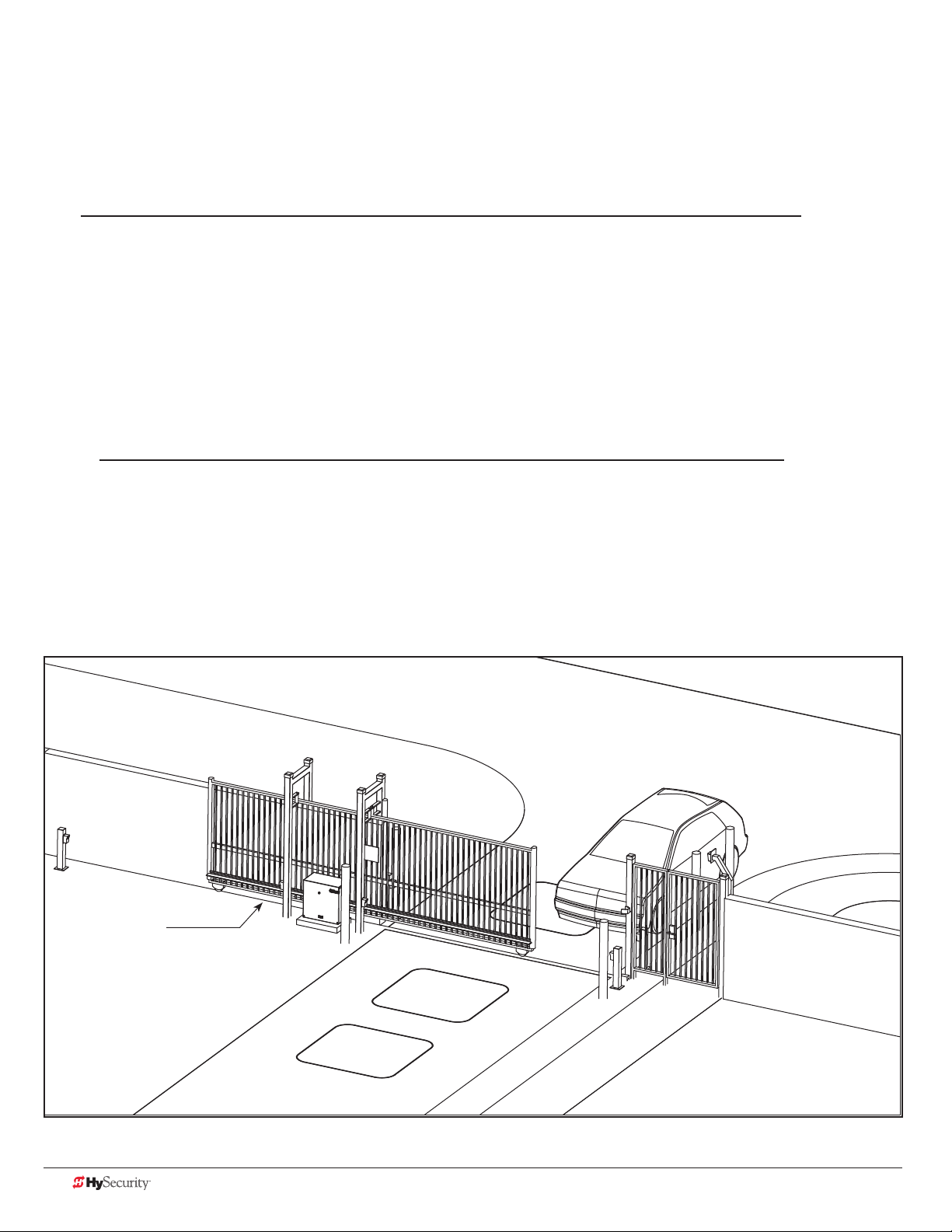
test tHe operator
Complete the installation by testing the operation of the gate.
NOTE: The operator must be turned on and in Run mode. A Run mode display appears on the STC. If a Run
mode status does not appear on the display, press Reset. If an error, alert, or fault appears on the display, refer to
the Troubleshooting section to learn how to clear the display and return to Run mode.
1. Press Open to open the gate.
2. Test the operator.
Cycle the gate a few times by pressing the Close and Open buttons.
If installed for emergency fast operation, test the EMERGENCY CLOSE using the constant hold
device. Observe the travel speed of the gate when you press and hold the Emergency Close button.
It will close a second or two faster than normal operation and ignore any photo eye, vehicle loop, or
other safety device inputs.
NOTE: If additional accessories are to be added, read about STC Inputs & Wiring on page 49.
XtremeDrive (rack)
shown
48 D0559 Rev. A SlideDriver/SlideDriver 50VF Series www.hysecurity.com
Page 57

STC Inputs & Wiring
This section provides information about the Smart Touch Controller, its inputs for peripheral connections, and its
monitoring capabilities. This section explains how to:
• Make Connections on the Smart Touch Controller
• Integrate with Security Systems
• Connect HY-5A Vehicle Detectors
• Connect Accessory Devices
Entrapment Sensor Connections
Access Controls
Push-button station
User Relays
Power Module
V
24
+
24V
A
C A
cce
s
s
or
y powe
r
ON
MM
CO
24V DC
Accessory Power (+)
Common Bus (-)
Stop Button* - 1
Open Button* - 2
Close Button* - 3
Remote Open and Radio Control - 4
Open / Close - 5
Open Partial - 6
Interlock Open / Time Clock Open - 7
Free Exit Detector - 8
Disable Exit Detector / Close Timer - 9
Inside Obstruction Vehicle Detector - 10
Outside Obstruction Vehicle Detector - 11
Shadow / Reset Vehicle Detector - 12
Edge Sensor - 13
Photo Eye Power (-) 24V Common - 14
Photo Eye Power (-) 24V Common - 15
DO NOT USE - 16
Photo Eye Open Direction - 17
DO NOT USE - 18
Photo Eye Close Direction - 19
DO NOT USE - 20
Charger AC Loss - 21
Gate Lock Interlock - 22
Emergency Close** - 23
Fire Department Open** - 24
Tact Push Button Switch
DRIVE
1
2
3
4
5
6
7
8
9
10
11
12
14
15
16
17
18
19
20
21
22
23
24
STOP BUTTON
OPEN BUTTON
CLOSE BUTTON
REMOTE OPEN AND
RADIO CONTROL
OPEN/CLOSE
OPEN PARTIAL
INTERLOCK OPEN
TIME CLOCK OPEN
FREE EXIT DETECTOR
DISABLE EXIT DETECTOR
DISABLE CLOSE TIMER
INSIDE OBSTRUCTION
VEHICLE DETECTOR
OUTSIDE OBSTRUCTION
VEHICLE DETECTOR
SHADOW/RESET
VEHICLE DETECTOR
EDGE SENSOR
PHOTO EYE POWER
24 VOLTS COMMON
PHOTO EYE POWER
DO NOT USE
PHOTO EYE
OPEN DIRECTION
DO NOT USE
PHOTO EYE
CLOSE DIRECTION
DO NOT USE
CHARGER
AC LOSS
LOCK INTERLOCK
EMERG CLOSE
FIRE DEPT OPEN
LED
Smart Touch Controller
LIMIT DUAL GATE
RPM
COM COMA B
Power Connector
POWER
USER 3
HySecurity
MX000585
VERSION
S/N
RADIO OPTIONS
DISPLAY
RS485
STATUS
RS232
COM
NO
COMOPEN EDGE+24V +24V
MOTOR USER 1
EXIT
USER 2
OBSTR
OBSTR
RESET
RS-485
STOP/BUZZER
Motor Relay
Reset & Buzzer Connector
FREE
User Relay 1
HY-5A Free Exit
User Relay 2
INSIDE
HY-5A Inside
Obstruction
User Relay 3 (DC Only)
OUTSIDE
Solid state for use with
flashers and other
VEHICLE DETECTORVEHICLE DETECTORVEHICLE DETECTOR
high cycle accessories
HY-5A Outside
Obstruction
Clock Battery
Heartbeat
SHADOW
Blinks green = operational
Red = alert, fault, or error
VEHICLE DETECTOR
HY-5A Shadow /
Reset*
RS-232 Connector
WIEGAND
Weigand Connector
LED lights
when energized
HY-5A
Limit Switch
Connectors
Master
Slave
Open
Radio
Gate
Edge Radio
www.hysecurity.com STC Inputs & Wiring D0559 Rev. A 49
Page 58
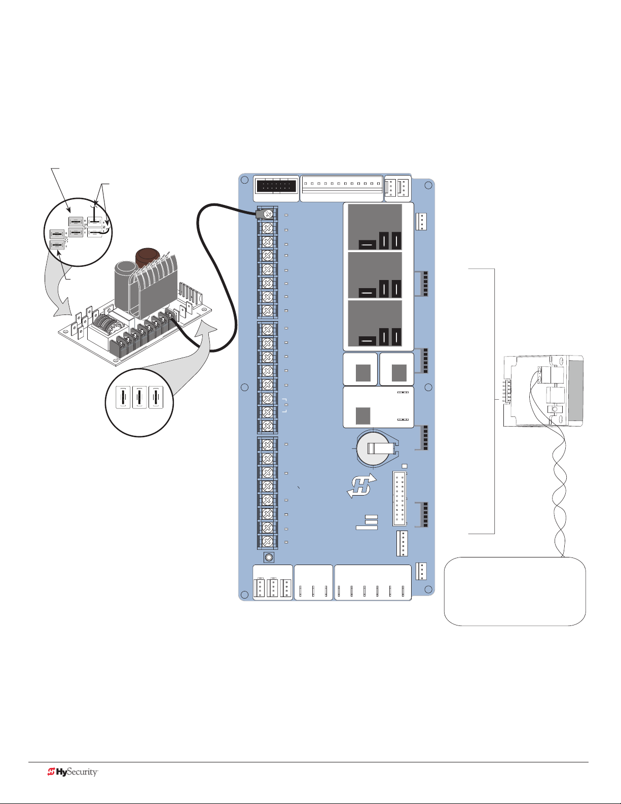
overvIew of tHe stC and power module
The Smart Touch Controller uses LED’s to indicate active inputs when AC power is present. For operators that use
only DC power, you can push a Tact push button to show the active inputs. This Tact push button is at the bottom
left corner beneath the #24 terminal input.
On a new operator, no active inputs should appear until external accessories and wiring are attached. If any
inputs are active before connecting external wiring, refer to Troubleshooting on page 73.
Motor contactor
Connections to VFD
Power Module
+ 24VAC
+ 24V DC
24V A
C
Acce
ss
or
y
powe
r
COMMON
+ 24VDC
Amp Draw on Power Supplies
Two power supplies are available:
24VDC and 24VAC
A maximum draw of 3A is allowable when
utilizing both power supply connections:
2 terminals 24VAC power or 24VDC on 3
terminals. Any combination of the 5 available
terminals can be used to draw the 3A maximum.
DRIVE
1
2
3
4
5
6
7
8
9
10
11
12
14
15
16
17
18
19
20
21
22
23
24
LIMITDUAL GATE
STOP BUTTON
OPEN BUTTON
CLOSE BUTTON
REMOTE OPEN AND
RADIO CONTROL
OPEN/CLOSE
OPEN PARTIAL
INTERLOCK OPEN
TIME CLOCK OPEN
FREE EXIT DETECTOR
DISABLE EXIT DETECTOR
DISABLE CLOSE TIMER
INSIDE OBSTRUCTION
VEHICLE DETECTOR
OUTSIDE OBSTRUCTION
VEHICLE DETECTOR
SHADOW/RESET
VEHICLE DETECTOR
EDGE SENSOR
PHOTO EYE POWER
24 VOLTS COMMON
PHOTO EYE POWER
DO NOT USE
PHOTO EYE
OPEN DIRECTION
DO NOT USE
PHOTO EYE
CLOSE DIRECTION
DO NOT USE
CHARGER
AC LOSS
LOCK INTERLOCK
EMERG CLOSE
FIRE DEPT OPEN
LED
Smart Touch Controller
RPM
COMCOMAB
Power Connector
POWER
USER 3
HySecurity
MX000585
VERSION
S/N
RADIO OPTIONS
RS485
STATUS
DISPLAY
RS232
COM
COMOPEN EDGE+24V +24V
STOP/BUZZER
MOTORUSER 1
FREE
EXIT
HY-5A
FREE EXIT
USER 2
INSIDE
OBSTR
HY-5A
HY-5A
INSIDE LOOP
OUTSIDE
OBSTR
NO
VEHICLE DETECTORVEHICLE DETECTORVEHICLE DETECTOR
HY-5A
OUTSIDE LOOP
SHADOW
RESET
VEHICLE DETECTOR
HY-5A
CENTER LOOP
WIEGAND
Smart Touch Controller
LOOP
Not to Scale
50 D0559 Rev. A SlideDriver/SlideDriver 50VF Series www.hysecurity.com
Page 59

IntegratIng wItH seCurItY sYstems
HySecurity hydraulic gate operators provides a 2-wire, serial interface (RS-485 connection) which allows remote
access to one or more operators. With software protocols provided by HySecurity, bi-directional status updates
and control commands are easily integrated with a central controller (computer or server), which becomes the
primary (master) to the connected operators. Up to 31 physical operators can be polled from the central master
command station. Reset requests, gate control, gate status, and gate faults can be monitored and information
can be retrieved from the central command station.
Gate operator connections to daisy-chain additional operators
PC/server connection
RS-485
2-wire serial interface
DRIVE
1
2
3
4
5
6
7
8
9
10
11
12
14
15
16
17
18
19
20
21
22
23
24
LIMIT DUAL GATE
STOP BUTTON
OPEN BUTTON
CLOSE BUTTON
REMOTE OPEN AND
RADIO CONTROL
OPEN/CLOSE
OPEN PARTIAL
INTERLOCK OPEN
TIME CLOCK OPEN
FREE EXIT DETECTOR
DISABLE EXIT DETECTOR
DISABLE CLOSE TIMER
INSIDE OBSTRUCTION
VEHICLE DETECTOR
OUTSIDE OBSTRUCTION
VEHICLE DETECTOR
SHADOW/RESET
VEHICLE DETECTOR
EDGE SENSOR
PHOTO EYE POWER
24 VOLTS COMMON
PHOTO EYE POWER
DO NOT USE
PHOTO EYE
OPEN DIRECTION
DO NOT USE
PHOTO EYE
CLOSE DIRECTION
DO NOT USE
CHARGER
AC LOSS
LOCK INTERLOCK
EMERG CLOSE
FIRE DEPT OPEN
LED
Smart Touch Controller
RPM
COMCOMAB
POWER
USER 3
HySecurity
MX000585
VERSION
S/N
RADIO OPTIONS
RS485
STATUS
DISPLAY
RS232
COM
NO
COMOPEN EDGE+24V +24V
STOP/BUZZER
MOTORUSER 1
FREE
EXIT
SA 1
STC ADDRESS
USER 2
INSIDE
OBSTR
OUTSIDE
OBSTR
VEHICLE DETECTORVEHICLE DETECTORVEHICLE DETECTOR
SA Display in the Installer Menu
SHADOW
RESET
Once the physical connection is made and protocols
are established, an SA (System Address) must be
VEHICLE DETECTOR
assigned for each operator through its Installer Menu.
For network communication, choosing a “SA” of 1 to 99
establishes individual network polling addresses. A “SA”
of zero means no network communication is desired.
If you plan to connect operators to a networked central
WIEGAND
master command station, contact HySecurity for
software protocols and additional information. Refer to
Contact Information on page 2.
Smart Touch Controller
www.hysecurity.com STC Inputs & Wiring D0559 Rev. A 51
Page 60

smart touCH Controller Inputs
When using AC power, an LED lights next to any active input.
1. Test the open and close function of the gate before wiring to accessory devices (external control inputs).
This makes it easier to troubleshoot if an unexpected functionality arises.
NOTE: If you are using the operator strictly in a DC capacity, the Smart Touch Controller has a tact button
you can push which lights an LED next to the active inputs. This button is in the bottom left corner of the
STC board. Press the SHOW LEDs push button switch to verify the status of the terminal inputs.
2. All the Smart Touch Controller inputs listed below are shown as a single input. The second wire is
connected to the Common Terminal Bus on the Power Module.
NOTE: The Emergency Close and Fire Dept. Open inputs are an exception and require a +24V input.
The +24V is located on Power Module next to the Common Bus. Refer to the drawing on page 54.
stC termInal Inputs
Use Terminal Inputs 4, 5, 6, and 7 for external control devices. DO NOT connect an external control device
to Input Terminals, 1, 2, or 3 unless the controls are located in clear view of the entire gate area and being
constantly monitored and supervised.
WARNING
STC Inputs Chart
No. STC Terminal Wire Connections Commonly used for...
1 Stop Button Normally Closed input. Jumper to
Common if input is not being used.
2 Open Button Do not use for radio or remote access
controls.
3 Close Button Do not use for radio or remote access
controls.
4 Remote Open &
Radio Control
5 Open/Close Button Connection for push button or radio
6 Open Partial NOTE: Terminal is only used in slide
7 Interlock Open/
Time Clock Open
LED
8 Free Exit Detector Refer to EB in the Installer Menu: Table
For radio/remote open device: Access
the RO from the User Menu and set to 1.
controls.
gates. Adjustable through the Installer
Menu from 7 to 99 seconds.
The default is Interlock Open (TC1) but
can be congured as the Time Clock
Open (TC 0) input. Refer to the Installer
Menu: Table 2 on page 42.
2 on page 42.
Line of sight, external stop button
or 3-button station.
Line of sight, external open
button or 3-button station.
Line of sight, external close
button or 3-button station.
Remote access control or radio
controls
Singular button device (multifunction)
Monitored access controls
Sequenced or interlocked gate
inputs. Another use for this input
is connection to a device that
regulates the open timing.
Vehicle detector, box type
connections for free exit loop.
52 D0559 Rev. A SlideDriver/SlideDriver 50VF Series www.hysecurity.com
Page 61

No. STC Terminal Wire Connections Commonly used for...
R
N
c
P
9 Disable Exit
Detector/Disable
Close Timer
Free Exit is only disabled if the Close
Limit Switch is tripped. If the gate is
partially opened, the Free Exit detector
Connection to free exit loop.
Installer menu enabled. Refer to
DT 0.
will trigger the gate to open fully.
10 Inside Obstruction
Vehicle Detector
11 Outside Obstruction
Vehicle Detector
Refer to the Installer Menu: Table 2 on
page 42.
Refer to CR 0 in the Installer Menu: Table
2 on page 42.
Vehicle detector, box type
connections inside reversing loop
Vehicle detector, box type
connections outside reversing
loop
12 Shadow/Reset
Vehicle Detector
Refer to CR, CB, and CP in the Installer
Menu: Table 2 on page 42.
Vehicle detector, box type
connections. Shadow function
for swing gates, reset function for
barrier arm gates.
13 Edge Sensor Refer to GC in the Installer Menu: Table
2 on page 42.
Gate edge, entrapment device
sensor connections. One input
works for both travel directions.
14 Photo Eye Power
(-) 24 Volts Common
15 Photo Eye Power
(-) 24 Volts Common
If photo eyes are used in place of vehicle
detector loops, connect 24V Common
to Power Supply COM & connect NO
output to appropriate vehicle loop
Photo eye open and close
connections.
detector input: Terminals 8, 10, 11 or 12.
Refer to Photo Eyes (Non-Contact)
Installation on page 61.
16 DO NOT USE
17 Photo Eye Open Refer to EO and PC in the Installer
Menu: Table 2 on page 42.
NOTE: Input disabled in HydraLift,
StrongArm and CRASH barrier arm
operators.
Photo eye open connection.
Connect NO or NC to Terminal
17 & COM where entrapment is a
concern such as the storage area
along a slide gate fence line.
18 DO NOT USE
19 Photo Eye Close Refer to EC and PC in the Installer
Menu: Table 2 on page 42.
If photo eye close connection
spans road: Connect NO or NC
output to Terminal 19 & COM.
20 DO NOT USE
21 Charger AC Loss Connection from battery cabinet. DC battery type operators only.
22 Gate Lock Interlock Refer to user relay option 23. Locking mechanisms.
23 Emergency Close Activate with +24. Refer to OC setting in
the Installer Menu: Table 2
on page 42.
Installer menu enabled and
input +24V to trigger. Requires
constant hold or supervised
input. Overrides photo eyes,
gates edges & vehicle detectors.
24 Fire Dept Open Jumper to +24. Refer to the Installer
Menu: Table 2 on page 42.
Installer menu FO enabled and
input +24V to trigger. Overrides
photo eyes and gates edges.
DRIVE
1
2
3
4
5
6
7
8
9
10
11
12
14
15
16
17
18
19
20
21
22
23
24
LIMIT DUAL GATE
STOP BUTTON
OPEN BUTTON
CLOSE BUTTON
REMOTE OPEN AND
RADIO CONTROL
OPEN/CLOSE
OPEN PARTIAL
INTERLOCK OPEN
TIME CLOCK OPEN
FREE EXIT DETECTOR
DISABLE EXIT DETECTO
DISABLE CLOSE TIMER
INSIDE OBSTRUCTION
VEHICLE DETECTOR
OUTSIDE OBSTRUCTIO
VEHICLE DETECTOR
SHADOW/RESET
VEHICLE DETECTOR
EDGE SENSOR
PHOTO EYE POWER
24 VOLTS COMMON
PHOTO EYE POWER
DO NOT USE
PHOTO EYE
OPEN DIRECTION
DO NOT USE
PHOTO EYE
CLOSE DIRECTION
DO NOT USE
CHARGER
AC LOSS
LOCK INTERLOCK
EMERG CLOSE
FIRE DEPT OPEN
LED
RPM
COMA B
Smart Tou
Tact Button
STC Inputs
www.hysecurity.com STC Inputs & Wiring D0559 Rev. A 53
Page 62

ConneCtIng aCCessorY devICes
Devices, such as gate edge sensors and photoelectric beams, must be installed to protect against entrapment.
These secondary entrapment protection devices are required for the gate installation to be in compliance with
UL 325 Safety Standards. NOTE: Always check your local area codes and comply with all regulations.
Standard accessory (entrapment and loop wire) connections are shown in the following illustration. All accessories
require a minimum of two connections:
• a device input
• a Common Bus Terminal (COM)
Power Connector
Two wires
attach to COM.
Conguration
depends on
whether AC or DC
powered.
24V
A
C A
cce
s
s
or
y powe
Power Module
r
Access controls
(Ex. Card reader, keypad_
Photo eye
DRIVE
1
2
3
4
5
6
7
C
D
V
24
+
8
9
ON
MM
O
C
10
11
12
14
15
16
17
18
19
20
21
22
23
24
LIMIT DUAL GATE
STOP BUTTON
OPEN BUTTON
CLOSE BUTTON
REMOTE OPEN AND
RADIO CONTROL
OPEN/CLOSE
OPEN PARTIAL
INTERLOCK OPEN
TIME CLOCK OPEN
FREE EXIT DETECTOR
DISABLE EXIT DETECTOR
DISABLE CLOSE TIMER
INSIDE OBSTRUCTION
VEHICLE DETECTOR
OUTSIDE OBSTRUCTION
VEHICLE DETECTOR
SHADOW/RESET
VEHICLE DETECTOR
EDGE SENSOR
PHOTO EYE POWER
24 VOLTS COMMON
PHOTO EYE POWER
DO NOT USE
PHOTO EYE
OPEN DIRECTION
DO NOT USE
PHOTO EYE
CLOSE DIRECTION
DO NOT USE
CHARGER
AC LOSS
LOCK INTERLOCK
EMERG CLOSE
FIRE DEPT OPEN
LED
Smart Touch Controller
RPM
COM COMA B
POWER
USER 3
HySecurity
MX000585
VERSION
S/N
RADIO OPTIONS
RS485
STATU S
DISPLAY
RS232
MOTOR USER 1
USER 2
COM
NO
COMOPEN EDGE+24V +24V
FREE
EXIT
INSIDE
OBSTR
OUTSIDE
OBSTR
SHADOW
RESET
STOP/BUZZER
HY-5A
FREE EXIT
HY-5A
INSIDE LOOP
VEHICLE DETECTORVEHICLE DETECTORVEHICLE DETECTOR
HY-5A
OUTSIDE LOOP
VEHICLE DETECTOR
HY-5A
CENTER LOOP
WIEGAND
HY-5A
Photo eye:
4-wire connection:
+24V
PHOTO EYE POWER (STC)
COM (Power module)
PHOTO EYE OPEN or CLOSE
(depending on function)
Edge
2 channel
radio receiver
LOOP
Not to Scale
sensor
Installer menu settings:
PC 0 = Normally Open
PC 1 = Normally Closed*
(*PC 1 is monitored photo eye)
54 D0559 Rev. A SlideDriver/SlideDriver 50VF Series www.hysecurity.com
Page 63

user relaYs – programmIng proCedure
The Smart Touch Controller is able to interface with many types of
external devices through the use of three user programmable output
relays: two mechanical relays (User 1 and User 2), and one solid state
relay (User 3) which is used most often for connection to ashing
devices.
All of the user relay functions identied and described in the table
below are accessible in the Installer Menu
(R1 x, R2 x, R3 x) selections.
NOTE: A setting of zero disables a User Relay. The User Relays will operate normally to 18VDC. Below 18VDC,
alert notication occurs. On Crash products User 3 relay is unavailable. It is pre-wired for the LED lights.
Use the STC buttons to program the user relays according to the following steps:
1. Select the relay you wish to use through the Installer
Menu: Table 2 on page 42. For example:
R1 13 (RELAY LOGIC 1) or R2 15 (RELAY LOGIC 2).
2. Select the appropriate function (1 through 28) by
changing the display to the associated number listed in
R1 1 CLOSE LIM
RELAY 1 LOGIC
the table. Use the Select, Next and Previous buttons to
make your selection. Refer to Menu Mode Navigation on
page 36.
Description
STC display (32 character OLED)
STC display (7-segment)
Identies relay number
Setting
Identies relay number
Setting
Performance
Programmable User Relays: Table 3
Setting Performance Description Wire
1 Close limit output Output can be used as an interlock signal to another
operator’s interlock input, or simply to indicate that the gate
is secure. The relay is “off” when the gate is closed. The relay
energizes when the fully-closed limit is released. (Any open
command energizes the relay.)
2 Close limit pulse output Used in a sequenced system to command a second machine
to close. Generates a brief pulsed output that occurs when
the close limit is triggered.
3 Open limit output Indicates a full-open position. This output becomes active
when an open-limit is triggered and deactivates when the
open-limit is released or a close command is received.
4 Open limit pulse output Used in a sequenced gate system to command a second
machine to open. Generates a brief pulsed output that
occurs when the open limit is triggered.
5 Warn before/during operate output Controls an external warning device. This output operates at
the same time as the internal warn before operate buzzer.
6 Gate Lock output Controls external solenoid or magnetic locks. In both
directions of travel, this output is activated about 7/10ths of
a second before the operator starts moving the gate and
remains active while moving. Output remains active, for a
few seconds, after stopping.
Connection
Relay 1, 2 or 3
Relay 1, 2 or 3
Relay 1, 2 or 3
Relay 1, 2 or 3
Relay 1, 2 or 3
Relay 1, 2 or 3
www.hysecurity.com STC Inputs & Wiring D0559 Rev. A 55
Page 64

Setting Performance Description Wire
7 Gate forced open output Activated if the gate is forced off the closed limit switch and
the operator is not able to restore the gate to full closed
position within four seconds.
NOTE: This alarm resets itself in 30 seconds.
8 Gate open too long output Controls an external device. Activates when the gate is open
longer than the user-selected period of time. Adjustable
from 0 seconds with 15 to 135s selectable delay timeframes
in 30s increments.
NOTE: TL - Open TIME ALERT adjustments can be made
in the Installer Menu. The TL Installer Menu display only
appears when using this relay.
9 Safety Mode Alert output Controls an external device. Activated when the system is
in Safety Mode or Entrapment Mode. Safety Mode occurs
when the gate encounters an obstruction. Entrapment
Mode means the gate is stopped and occurs if the internal
inherent sensor triggers while the system is in Safety Mode.
10 Entrapment Mode Alert output Controls an external device. Activated only when in the
Entrapment Mode.
11 Unauthorized Vehicle Entry output
(Tail gate alert)
12 Outside Obstruction Vehicle
Detector output
13 Loitering Alert Indicates a vehicle is loitering on the Outside Obstruction
Controls an external device. Activated when a second vehicle
enters from the outside without a valid input from an access
control device. This output releases when an access control
input signals open or the arm/gate reaches the close limit.
Interlocks an entry device to prevent pedestrian use. This
output is active whenever the Outside Obstruction Loop
Detector is tripped.
Loop. Adjustable from 0 seconds with 15 to 135s selectable
delay timeframes in 30s increments.
Connection
Relay 1, 2 or 3
Relay 1, 2 or 3
Relay 1, 2 or 3
Relay 1, 2 or 3
Relay 1, 2 or 3
Relay 1, 2 or 3
Relay 1, 2 or 3
NOTE: LT LOITERING ALERT adjustments can be made
in the Installer Menu. The LT Installer Menu display only
appears when using this relay.
14 Gate nearing full travel output Applies to operators with position sensors only. Activated
when the gate is 3s from expected limit switch trigger.
NOTE: If the operator has not yet learned limits, it will
energize Relay 14 when the motor begins moving the gate.
15 Gate failure output Activated to report occurrence of a problem. Indicates
the system is in an Error Mode, Fault Mode or Entrapment
Mode.
16 Motor Running output Active when the motor is running and gate is in motion. Relay 1, 2 or 3
17 AC Power Failure output This relay is normally energized and drops with loss of AC
power.
18 DC Power Failure output DC operators only. The relay activates when the battery
power is very low, but the output ceases when the battery is
dead. The relay is triggered when the battery is less than 20
volts.
19 Flasher Relay Flashes lights once per second. The relay is constantly
pulsing except when the open limit switch is triggered.
* Preferred connection is Relay 3, a solid state relay (except
on Crash operators). On Crash products, Relay 3 is hardwired for the LED barrier arm lights.
20 Free Exit Loop Vehicle Detector
output
Active when the Free Exit Loop is tripped. Relay 1, 2 or 3
Relay 1, 2 or 3
Relay 1, 2 or 3
Relay 1, 2 or 3
Relay 1, 2 or 3
Relay 1 or 2*
(Relay 3)
56 D0559 Rev. A SlideDriver/SlideDriver 50VF Series www.hysecurity.com
Page 65

Setting Performance Description Wire
Connection
21 Inside Obstruction Vehicle Detector
output
22 Reset Loop Detector output Active when the Reset loop detector is tripped. Relay 1, 2 or 3
23 External Latching gate Lock Output Activates when the Lock Interlock Input (Terminal No. 22)
24 Gate at Partial Open Position Active when the partial open position is reached or
25 DC Power Alert Deactivates when the software detects a low battery voltage
26 Free Vehicle Detector Pulse Activates when the Exit Loop Detector is tripped and causes
27 Not Open (requires AC power) When AC power is detected, this relay activates when the
28 Flasher (requires AC power) Controls ashing lights that pulse 500ms per second. The
29 Test Output For factory testing purposes
Active when the Inside Obstruction loops is tripped. Relay 1, 2 or 3
Relay 1, 2 or 3
is active at the start of an Open cycle and remains on until
the Lock Interlock releases or 10 seconds elapse, whichever
happens sooner. Also, activates a Close cycle and releases 1
second after reaching the Close limit.
Relay 1, 2 or 3
exceeded. Not used in StrongArm Crash.
Relay 3
(below 21VDC, but greater than 18VDC) for a duration of
2 seconds or more. To slow battery drain, accessory power
loads are shed.
Relay 1, 2 or 3
a 250mS pulse output to occur.
Relay 1, 2 or 3
gate in NOT on the open limit. If AC power fails, or the gate
is on the open limit, the relay is deactivated.
Relay 1, 2 or 3
relay is constantly activating except when the open limit
switch is triggered or AC power fails.
HY8relaY module optIon
The Hy8Relay (extended relay module) provides 8 numbered mechanical relays. R 4, RELAY 4 LOGIC through
RB, RELAY 11 LOGIC can be access through the Installer Menu. Set the number for the relay based on the
information found in Tables 4 or 5. Table 5 is oriented toward revenue control parking lot applications.
Wire communication cable connections between the DUAL GATE ports, at the base of the STC, and the
extended mechanical relay module.
www.hysecurity.com STC Inputs & Wiring D0559 Rev. A 57
Page 66

veHICle deteCtor logIC
HySecurity recommends that vehicle detectors be used for free exit and obstruction sensing logic only. The
exception is in parking or barrier arm applications where detectors may also be used to close the gate. In
applications employing our swing, vertical lift, or sliding gate operators, closing logic cannot be used except
when the anti-tailgate logic is employed.
Vehicle detector functions (OR IR, HD, DL ) are congurable through the Installer Menu: Table 2 on page 42.
TailGate Alert
User Relay 11 is available for notication devices. If a vehicle is tailgating, and a asher or audio device is
connected to User Relay 11, the relay will be triggered by the tailgating vehicle crossing the loops.
Anti-TailGate Mode Selection
The Detector Logic (DL) menu item, found in the Installer Menu: Table 2 on page 42, lets you set the anti-
tailgate mode. This menu item works in conjunction with the Close Timer (CT) when the vehicle detector is
triggered. If you plan to use the anti-tailgate feature, check the time delay aspect of the Close Timer (CL) setting.
The four selectable modes for DL are as follows:
Mode 1 (Default): An input from either the Free Exit, Outside Obstruction Loop, Inside Obstruction Loop, or the
Center Loop will hold the gate open, reset the close timer, and ignore all close inputs. The close timer begins to
count down only after all vehicle detectors are clear and no other open command is present.
Mode 2: The close timer does not wait for vehicle detectors to clear, but instead it starts counting down as soon
as the open limit is reached.
Mode 3: When both inside and outside obstruction loops are simultaneously active, the gate will close
immediately once all vehicle detectors are no longer triggered (vehicle loops clear) unless another open
command is present.
Mode 4: Full anti-tailgate logic includes Mode 3 functions. In addition, the gate will stop during the opening
cycle when both OOLD & IOLD are tripped simultaneously. When the OOLD & IOLD loops are cleared, the gate
closes immediately. The OOLD & IOLD can be individually set so that, if tripped while closing, the gate may
either, pause only or reverse to reopen. The free exit detector input is ignored while the gate is closing.
NOTICE: Using any vehicle detector logic mode other than Mode 1 (default) requires that all the loops be placed
with the geometry and spacing as shown in the layout drawings on page 70 and 71. The detector Modes 3
and 4 require use of separate inner and outer obstruction detectors.
58 D0559 Rev. A SlideDriver/SlideDriver 50VF Series www.hysecurity.com
Page 67

veHICle deteCtor InstallatIon: HY-5a
The Smart Touch Controller provides an interface for up to four different vehicle detector functions.
Standard box type 11 pin (24 VDC or 24 VAC) vehicle detectors may be connected in the traditional manner, but
HySecurity HY-5A mini-detector modules plug directly into the Smart Touch Controller, making eld installation
much faster and enhancing performance. The detector communicates with the Smart Touch Controller
microprocessor to achieve the following benets:
• Loop frequency is automatically set and monitored by the Smart Touch Controller.
• Best operating frequency for each loop is automatically selected.
• Cross-talk between multiple loops is impossible.
• Very low power draw, which is important for maximum UPS capability during a power failure or for solar
applications.
• Loop frequency and call strength can be reported on the Smart Touch Controller display.
• Loop malfunctions are stored by the Smart Touch Controller and appear in code on the display.
NOTE: It is not mandatory to use two separate vehicle detectors for inner and outer obstruction detection;
however, the benets of using the two HY-5A detectors are great. Several new features are possible, such as
second vehicle tailgating detection, loitering alert, and selectable non-reversing options.
Screw terminals
for loop wire
Adjustable
Vehicle loop
sensitivity dial
Status LED
Standoff Supports
(Inset into the holes
in the Control Box.)
HY-5A
Vehicle loop sensitivity levels
explained on the front label.
Metal pins t into a socket on
the Smart Touch Controller.
HY-5A Vehicle Detector Module
www.hysecurity.com STC Inputs & Wiring D0559 Rev. A 59
Page 68

Four vehicle detector inputs (terminals: 8, 10, 11, and 12) exist on the Smart Touch Controller, as well as the four
direct plug ins for the HY-5A modules. Refer to Overview of the STC and Power Module on page 50.
The vehicle detector input functions are as follows:
• Free Exit Loop Detector - Opens a fully closed gate.
• Outside Obstruction Loop Detector (Out Obs Loop) - Triggered by the outside (public side) vehicle
detector loop
• Inside Obstruction Loop Detector (In Obs Loop) - Triggered by the inside (secure side) vehicle detector
loop
• Center/Reset/Shadow Loop Detector - On barrier arm gates, prevents closure when active. On swing
gates, prevents gate from opening or closing when the vehicle detector is active.
NOTE: Use of any combination of HY-5A detectors and box detectors is acceptable. On occasion, multiple
obstruction detectors may be mandatory. For example, an area greater than 200 square feet (61 square meters)
of vehicle loop cannot be connected to any one detector because the sensitivity becomes inadequate.
ConneCtIng HY-5a veHICle deteCtors
NOTE: Refer to the installation instructions provided with the HY-5A vehicle detectors. It provides detailed
illustrations and instructions that are not found in the steps below.
A quick overview on how to install the HY-5A Vehicle Detector modules, one at a time, follows:
1. Turn off the AC power switch on the Control Box.
Squared off end of
standoff
2. Insert the locking end of the two white plastic standoffs into the
mounting holes on the detector.
3. Plug the detector into the appropriate socket along the right
edge of the Smart Touch Controller. Be careful to align the six
detector pins into the socket correctly (the screws for tightening
the terminals should face toward the board), and then snap the
standoffs into the holes in the control box.
4. Route the loop wires through the holes provided in the control
box and connect the loop leads to the two terminals on the HY-5A
detector. Tighten the terminal screws securely.
5. To enable the detector, turn on power. The detector will
immediately tune if it is connected to a vehicle loop. Make sure no
cars or other metal objects are over the loop.
6. Repeat Steps 1 through 5 for each HY-5A detector.
7. If the detector module is unplugged after it is enabled, a communications alert (ALERT 10) will be
triggered. If the fault is not resolved, an error message, ERROR 3 “Detector Failed” is displayed.
NOTE: If there is any detector fault, the gate operator functions as if the detector is triggered.
60 D0559 Rev. A SlideDriver/SlideDriver 50VF Series www.hysecurity.com
Page 69

Pressing the RESET button:
Clears any errors
Tunes the detectors on connected loops
Un-installs any detectors that have been removed
8. The Smart Touch Controller automatically governs frequency selection for all HY-5A detector modules.
This simplies installation and guarantees that there is no cross-talk between multiple loops. The
frequency and call level can also be manually selected; if this is required, refer to the appropriate loop
set ( ELD, ILD, OLD, RLD) in the Installer Menu: Table 2 on page 42.
9. Sensitivity is the only adjustment available on the detector itself. Generally, sensitivity does not need to be
increased unless the loop is large or there are multiple loops connected to one detector.
NOTE: Do not exceed more than 200 square feet (61 square meters) of loop area to one detector.
If required, adjust the sensitivity using the rotary dial.
4
5
3
6
2
7
1
The factory default setting is 1.
0
0 = Low with boost* 4 = Low without boost
Rotary dial
1 = Normal with boost* 5 = Normal without boost
2 = Medium with boost* 6 = Medium without boost
3 = High with boost* 7 = High without boost
NOTE: *A boost feature is applied for settings 0 through 3. Boost increases the sensitivity
during a call and is useful for maintaining continuous detection if the signal becomes weak
(such as with tractor-trailer trucks). Sensitivity settings 4 through 7 are the same as 0
through 3, but without the boost feature.
pHoto eYes (non-ContaCt) InstallatIon
Plan to integrate photo eyes (photoelectric sensors) in your site plan. Photo eyes are wired to the STC and
require low voltage conduit to the operator and power supply. If your site conditions require a battery-powered
transmitter, it can be ordered through your distributor.
Understand your site requirements and use the layout diagrams available in the appendix to determine the most
appropriate mounting positions for any additional photo eyes. The Smart Touch Controller has two photoelectric
sensor inputs (Photo eye open and Photo eye close).
If there are no other secondary external entrapment protection sensors (typically an edge sensor), then for slide
gates, swing gates or any site that must comply with UL 325 regulations, at least two photo eyes are required to
serve and reverse the gate in each direction of travel.
The two common photoelectric sensor types are thru-beam and retro-reective; each has its advantages. A
thru-beam sensor is generally more powerful and able to function reliably with dirty optics and in poor weather.
www.hysecurity.com STC Inputs & Wiring D0559 Rev. A 61
Page 70

A retro-reective sensor has the convenience of not requiring the installation and electrical wiring of the remote
emitter required in a thru beam system, but is generally less reliable in poor weather.
NOTE: In an outdoor environment because of reduced performance, avoid using a retro-reective device to span
a distance greater than 24 feet (7.3 meters).
Compatibility
The UL 325 standard requires that a photoelectric sensor be laboratory tested and “recognized” under UL 325.
In order to be compatible with all HySecurity operators, a photo eye must be rated to function from 24 VDC
source power.
Installation
Install additional photo eyes according to the following steps.
1. Locate the photo eye approximately 15 to 30 inches (38 to 76 cm) above the ground and as close to the
gate as possible. Refer to site layout below.
2. Mount the receivers on the left or right side of the gate operator.
3. Mount the emitters just beyond the travel of the gate in the fully-closed position.
NOTE: The installation locations are intended for pedestrian detection. If photo eyes are also to be used for
vehicular detection, consider (in addition to the low elevation photo eye for cars) installing another photo eye
at a height of about 55 inches (140 cm) to detect semi (tractor- trailer) trucks.
Public Side
Photo eye
Photo eye
Photo eye
Secure Side
Photo eye
Pedestrian
Gate
62 D0559 Rev. A SlideDriver/SlideDriver 50VF Series www.hysecurity.com
Page 71

Configuration
STOP BUTTON
OPEN BUTTON
CLOSE BUTTON
REMOTE OPEN AND
RADIO CONTROL
OPEN/CLOSE
1
OPEN PARTIAL
INTERLOCK OPEN
TIME CLOCK OPEN
FREE EXIT DETECTOR
DISABLE EXIT DETECTOR
DISABLE CLOSE TIMER
INSIDE OBSTRUCTION
VEHICLE DETECTOR
OUTSIDE OBSTRUCTION
VEHICLE DETECTOR
SHADOW/RESET
VEHICLE DETECTOR
EDGE SENSOR
PHOTO EYE POWER
24 VOLTS COMMON
PHOTO EYE POWER
DO NOT USE
PHOTO EYE
OPEN DIRECTION
DO NOT USE
PHOTO EYE
CLOSE DIRECTION
DO NOT USE
CHARGER
AC LOSS
LOCK INTERLOCK
EMERG CLOSE
FIRE DEPT OPEN
2
3
4
5
6
7
8
9
10
11
12
14
15
16
17
18
19
20
21
22
23
24
Smart Touch Controller
LIMIT DUAL GATE
RADIO OPTIONS
DRIVE
POWER
RS485
MOTOR USER 1
USER 2
USER 3
VEHICLE DETECTORVEHICLE DETECTORVEHICLE DETECTOR
STOP/BUZZER
FREE
EXIT
INSIDE
OBSTR
OUTSIDE
OBSTR
SHADOW
RESET
WIEGAND
HySecurity
COM
NO
MX000585
VERSION
S/N
RS232
DISPLAY
VEHICLE DETECTOR
COM COMA B
RPM
COMOPEN EDGE+24V +24V
STATUS
LED
24V
A
C A
cce
s
s
or
y powe
r
+
24
V
D
C
Power Connector
C
O
MM
ON
Congure the photo eyes according to the following procedure.
1. If the photo eye has an internal switch for setting Light Operate versus Dark Operate, select Light
Operate.
2. If the photo eye has a relay output and has both NO and NC terminals, some experimentation may be
required to determine the proper connection because, when its in the Light Operate mode, the output
relay is normally energized and releases when the beam is blocked.
NOTE: Some manufacturers label an output as NO (normally open), when it is actually an NC (normally closed)
contact.
If the photo eye has a solid-state output, you must choose a sinking-type connection.
Photo Eye Connections
Connect the three wires to the receiver and two wires
to the emitter according to the following procedure.
1. Obtain the +24 Volt source power at one of the
three spade-terminals on the power module.
2. Obtain the 24 Volt Common from screwterminals 14 or 15 (which are labeled Photo
Eye Power Common) on the Smart Touch
Controller.
Power Module
NOTE: The -24 Volt Photo Eye Power also
supplies the photo eye output Common.
Additional photo eye
3. Perform the following, as applicable:
connections
If the photo eye spans the road, connect
the NO or NC output to Terminal No. 19
on the Smart Touch Controller.
If the photo eye spans the gate’s open
storage area as in a slide gate scenario,
connect the NO or NC output to Terminal
No. 17 on the Smart Touch Controller. (Not
used on StrongArm M30/M50.)
www.hysecurity.com STC Inputs & Wiring D0559 Rev. A 63
Integrated Photo
eye connections in
StrongArm M30/M50
Page 72

Photo Eye Alignment
Most photo eyes require careful optical alignment in order to aim the emitter beam to the center of the receiver
or reector. In order to avoid false triggering, it is important to carefully align the system, especially with retroreective photoelectric sensors. To that end, HySecurity has provided a unique feature that turns power on to the
photo eyes and causes a buzzer to chirp when the photo eye enters and exits alignment. Align the photo eyes
using this feature by taking the following steps:
1. Move the gate off (away from) the close limit.
2. Access the User Menu and select PE. Refer to User Menu: Table 1 on page 39.
3. Set the menu item PE 0 to PE 1.
4. More the photo eyes to align the emitter beam. The buzzer will chirp twice when the beam is broken and
once when remade.
5. When the buzzer chirps once, indicating the photo eyes are aligned, close the gate. When the close limit
is triggered, the menu item PE resets to 0.
Monitored Connection
A monitored connection tests for the presence and correct operation of the photo eye prior to each gate
activation and prevents gate operation if any fault is present. The Installer Menu item PC 0 must be changed to
PC 1 to enable this feature.
Photo Eye Function
If the gate is stationary, a tripped photo eye will prevent the gate from starting in either direction. If tripped while
in motion, the standard function is to pause the gate motion and then automatically restart again if the photo eye
is clear within ve seconds. An optional setting in the Installer Menu will cause a 2 second reversal of travel. Refer
to EC and EO in Installer Menu: Table 2 on page 42.
64 D0559 Rev. A SlideDriver/SlideDriver 50VF Series www.hysecurity.com
Page 73

Dual Gate Systems
Conguring two or more operators to work together as an interlocked pair (Primary/Secondary or Sally Port) or
sequenced gate system is easy to do with the Smart Touch Controller. There is no need to order a special model
or any adapters. The area of the board marked Dual Gate employs a 3-wire RS-485 serial port for communication
between the operators.
ConneCtIng an InterloCKed paIr (dual gate)
The Smart Touch Controller (STC) provides dual gate connections and programming features to connect a pair
of gate operators in a Primary/Secondary or interlocked Sally Port conguration. The STC software establishes
the communication protocols when wiring the two gate operators. A Primary/Secondary pair of operators can be
set for different open/close timing sequences and Sally Port gates are often used at correctional facilities. In Sally
Port congurations, one operator cannot open unless the other is fully closed. To learn how to connect the wiring
between operators, review the wire diagram on the next page.
NOTE: The operators do not have to be of the same type, but both need to have the most current and up-todate software version installed on the Smart Touch Controller. A StrongArm M30/M50 can be interlocked with
a SlideDriver to provide both crash and personnel security. The STC software integrates seamlessly between
operators.
RS-485 communication is available for networked security systems. Refer to Integrating with Security Systems on
page 51 for additional information.
www.hysecurity.com Dual Gate Systems D0559 Rev. A 65
Page 74

Dual Gate Wiring Connections
CAUTION
To connect an interlocked pair of gate operators, simply follow the steps below.
1. As shown in the Wire Diagram, connect a shielded communications cable to the DUAL GATE inputs in
each operator. The inputs are located near the base of the Smart Touch Controller. Be sure to connect the
wires in pairs to the same terminal ports (A-A, B-B, COM-COM) on both operators.
2. Attach a ring terminal to the shield wire and connect it to the Smart Touch Controller’s convenient ground
screw.
Connect the ground shield wire to only one operator, not both. Use only 18-20 gauge twisted and shielded triple
wire. To operate properly, both Smart Touch Controllers must be using the same software version.
DRIVE
1
2
3
4
5
6
7
8
9
10
11
12
14
15
16
17
18
19
20
21
22
23
24
STOP BUTTON
OPEN BUTTON
CLOSE BUTTON
REMOTE OPEN AND
RADIO CONTROL
OPEN/CLOSE
OPEN PARTIAL
INTERLOCK OPEN
TIME CLOCK OPEN
FREE EXIT DETECTOR
DISABLE EXIT DETECTOR
DISABLE CLOSE TIMER
INSIDE OBSTRUCTION
VEHICLE DETECTOR
OUTSIDE OBSTRUCTION
VEHICLE DETECTOR
SHADOW/RESET
VEHICLE DETECTOR
EDGE SENSOR
PHOTO EYE POWER
24 VOLTS COMMON
PHOTO EYE POWER
DO NOT USE
PHOTO EYE
OPEN DIRECTION
DO NOT USE
PHOTO EYE
CLOSE DIRECTION
DO NOT USE
CHARGER
AC LOSS
LOCK INTERLOCK
EMERG CLOSE
FIRE DEPT OPEN
LED
Smart Touch Controller
LIMIT DUAL GATE
RPM
COMCOMAB
POWER
USER 3
HySecurity
MX000585
VERSION
S/N
RADIO OPTIONS
RS485
STATUS
DISPLAY
RS232
COM
STOP/BUZZER
MOTORUSER 1
FREE
EXIT
USER 2
INSIDE
OBSTR
OUTSIDE
OBSTR
NO
VEHICLE DETECTORVEHICLE DETECTORVEHICLE DETECTOR
SHADOW
RESET
VEHICLE DETECTOR
WIEGAND
COMOPEN EDGE+24V +24V
Wire Diagram: Interlocked Pair of Operators using DUAL GATE Wiring
66 D0559 Rev. A SlideDriver/SlideDriver 50VF Series www.hysecurity.com
Page 75

Dual or Sequenced Gates: Power, Software & Accessory Requirements
When installing an interlocked pair, the following must be adhered to:
• An electrical conduit for interconnecting wires must span between the two operators. The interlock
(dual gate) communication wires and any low voltage control wires must be installed in a conduit that is
separate from the high voltage power cables.
• Complete the installation of both operators as separate machines and verify that their basic functions are
correct as solo operators before interconnecting them.
• Be sure both operators are running the same software. The software version can be viewed on the display
by pressing the RESET button.
• Keep the most current software loaded. It is available at http://www.hysecurity.com. Make it part of your
maintenance routine to check for and install software updates on a regular basis.
• External control inputs (vehicle detectors and entrapment protection sensors) may be connected to
either gate operator in a Primary/Secondary conguration, but in a Sally Port conguration, the external
control inputs must be connected to Sally Port A. (Sally Port A being the rst gate to open for incoming
trafc. Be sure to designate Sally Port A in the dual gate menu item as 3 (DG 3) and Sally Port B as
4 (DG 4).
Programming a Dual Gate (Interlocked Pair)
Both gate operators must be programmed so they know what function they are to perform as Primary and
Secondary or Sally Port A and Sally Port B. (Sally Port A being the rst
gate to open for incoming trafc.) The Installer Menu provides the Dual
Gate (DG) menu item that sets up the functionality of the gate operators.
Access this menu item by taking the following steps:
Press Menu twice at
Status Display
User Menu
CT 0 or HC 1
To access the Installer Menu,
press and hold Reset & Open,
and then release them.
Refer to the table below to set the operator’s functionality.**
**Interlocked Gate type Operator 1 (Primary) Operator 2 (Secondary)
Sally Port
Primary / Secondary
the gate status display.
Installer Menu Dual Gate
FD 0 DG 0
Press Next until DG
characters appear.
1. Press Next until DG 3 appears on the display.
2. Press Select to establish the operator as
Sally Port A.
1. Press Next until DG 2 appears on the display.
2. Press Select to establish the operator as
Primary.
Press Select so DG
characters blink.
Press Next to change
the display. Refer to
chart below.
1. Press Next until DG 4 appears on the display.
2. Press Select to establish the operator as
Sally Port B.
1. Press Next until DG 1 appears on the display.
2. Press Select to establish the operator as
Secondary.
DG 0
DUAL GATE
www.hysecurity.com Dual Gate Systems D0559 Rev. A 67
Page 76
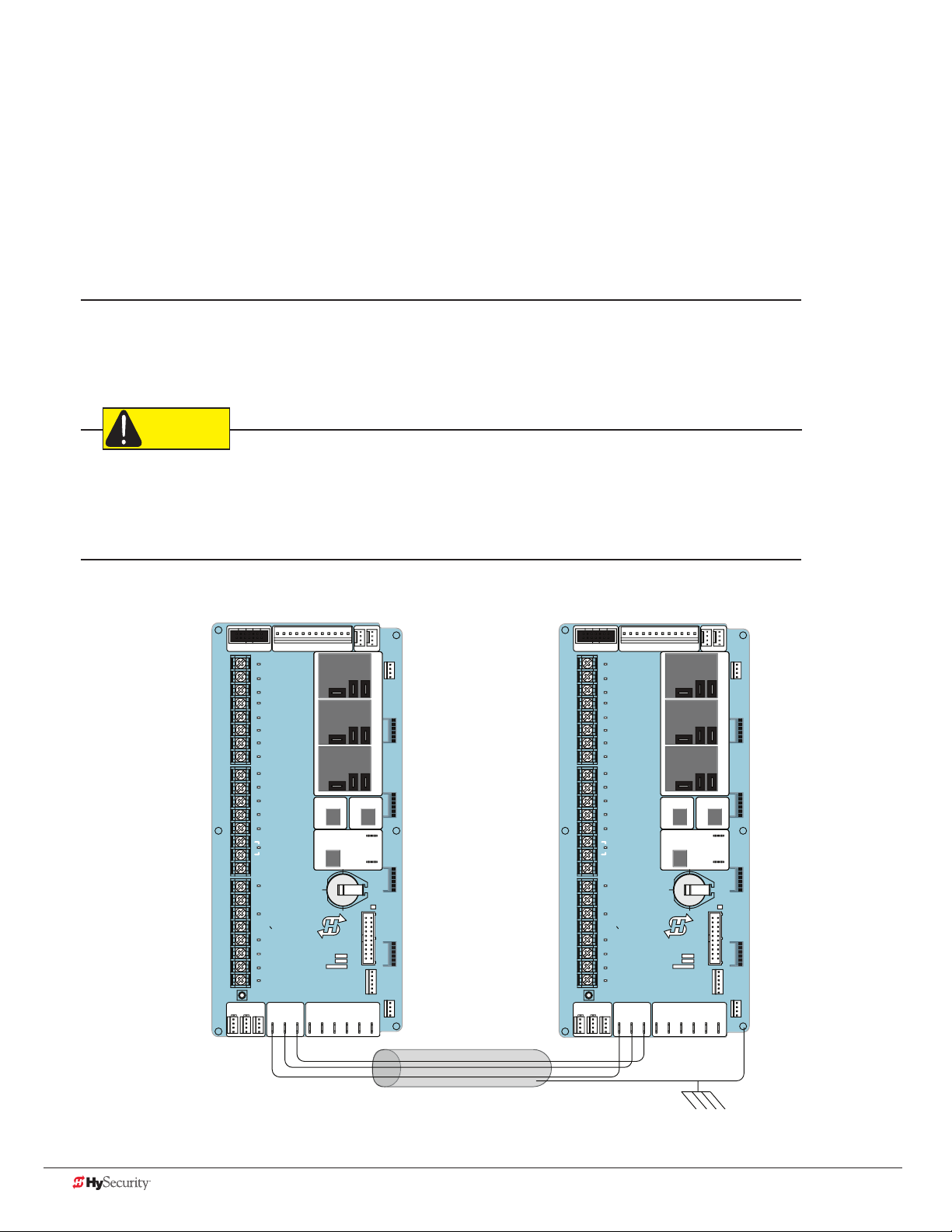
ConneCtIng sequenCed gates
CAUTION
Sequenced gates are slightly different than dual or interlocked gates. When two gate operators are connected as
sequenced gates, a faster “Trafc Control Gate” operator (i.e. barrier arm or crash wedge) and a slower “Security
Gate” operator (slide, swing, or vertical lift gate) operate in sequence to help prevent tailgating by unauthorized
vehicles. Both operators open (Security Gate rst followed by the Trafc Control Gate) and allow a vehicle
through, but the faster moving Trafc Control Gate closes quickly once its reset/center loop and all obstruction
loops are cleared. Upon reaching its closed limit, the Trafc Control Gate signals the Security Gate to close. Note
that all shared vehicle detector loops must be cleared before the Security Gate closes.
NOTE: An emergency open or close overrides the gate sequencing and acts upon both gates simultaneously.
The Smart Touch Controller (STC) provides the sequenced gate connections and programming features, and the
STC software establishes the communication protocols when wiring the sequenced gate operators. To learn how
to connect the wiring between operators, review the Wire Diagram below.
The operators do not have to be of the same type, but both need to have the most current and up-to-date
software version installed on the Smart Touch Controller. A StrongArm M30/M50 can be sequenced with a
SlideDriver to provide both crash and personnel security. The inherent STC software integrates seamlessly
between operators and software protocols and allows RS-485 communication for networked security systems.
Refer to Integrating with Security Systems on page 51 for additional information.
To connect a sequenced pair of gate operators, follow the steps on the next page.
DRIVE
STOP BUTTON
1
2
OPEN BUTTON
3
CLOSE BUTTON
REMOTE OPEN AND
4
RADIO CONTROL
5
OPEN/CLOSE
OPEN PARTIAL
6
INTERLOCK OPEN
7
TIME CLOCK OPEN
FREE EXIT DETECTOR
8
DISABLE EXIT DETECTOR
9
DISABLE CLOSE TIMER
INSIDE OBSTRUCTION
10
VEHICLE DETECTOR
OUTSIDE OBSTRUCTION
11
VEHICLE DETECTOR
SHADOW/RESET
12
VEHICLE DETECTOR
EDGE SENSOR
14
PHOTO EYE POWER
24 VOLTS COMMON
PHOTO EYE POWER
15
DO NOT USE
16
PHOTO EYE
17
OPEN DIRECTION
DO NOT USE
18
PHOTO EYE
19
CLOSE DIRECTION
20
DO NOT USE
CHARGER
21
AC LOSS
LOCK INTERLOCK
22
EMERG CLOSE
23
FIRE DEPT OPEN
24
LED
LIMIT DUAL GATE
RPM
COMCOMAB
POWER
USER 3
HySecurity
MX000585
VERSION
S/N
Smart Touch Controller
RADIO OPTIONS
DISPLAY
RS485
STATUS
STOP/BUZZER
MOTORUSER 1
FREE
EXIT
DRIVE
1
2
3
4
5
6
USER 2
INSIDE
OBSTR
7
8
9
10
11
12
OUTSIDE
OBSTR
COM
NO
VEHICLE DETECTORVEHICLE DETECTORVEHICLE DETECTOR
14
15
16
17
18
SHADOW
RESET
VEHICLE DETECTOR
19
20
21
22
RS232
WIEGAND
COMOPEN EDGE+24V +24V
23
24
LED
LIMIT DUAL GATE
RPM
POWER
STOP BUTTON
OPEN BUTTON
CLOSE BUTTON
REMOTE OPEN AND
RADIO CONTROL
OPEN/CLOSE
OPEN PARTIAL
INTERLOCK OPEN
TIME CLOCK OPEN
FREE EXIT DETECTOR
DISABLE EXIT DETECTOR
DISABLE CLOSE TIMER
INSIDE OBSTRUCTION
VEHICLE DETECTOR
OUTSIDE OBSTRUCTION
VEHICLE DETECTOR
SHADOW/RESET
VEHICLE DETECTOR
EDGE SENSOR
PHOTO EYE POWER
24 VOLTS COMMON
PHOTO EYE POWER
DO NOT USE
PHOTO EYE
OPEN DIRECTION
DO NOT USE
PHOTO EYE
CLOSE DIRECTION
DO NOT USE
CHARGER
AC LOSS
LOCK INTERLOCK
EMERG CLOSE
FIRE DEPT OPEN
Smart Touch Controller
COMCOMAB
USER 3
HySecurity
MX000585
VERSION
S/N
RADIO OPTIONS
DISPLAY
RS485
STATUS
RS232
STOP/BUZZER
MOTORUSER 1
FREE
EXIT
USER 2
INSIDE
OBSTR
OUTSIDE
OBSTR
COM
NO
VEHICLE DETECTORVEHICLE DETECTORVEHICLE DETECTOR
SHADOW
RESET
VEHICLE DETECTOR
WIEGAND
COMOPEN EDGE+24V +24V
Wire Diagram: Sequenced Pair of Operators using DUAL GATE Inputs
68 D0559 Rev. A SlideDriver/SlideDriver 50VF Series www.hysecurity.com
Page 77

1. As shown in the wire diagram on page 68, connect a shielded communications cable to the DUAL
GATE inputs in each operator. The inputs are located near the base of the Smart Touch Controller. Be sure
to connect the wires in pairs to the same terminal ports (A-A, B-B, COM-COM) on both operators.
2. Attach a ring terminal to the shield wire and connect it to
the Smart Touch Controller’s convenient ground screw.
NOTE: Connect the ground shield wire to only one operator,
not both. Use only 18-20 gauge twisted and shielded triple wire.
SG 0
SEQUENTIAL GATE
Sequenced gates are very similar to dual gates (interlocked pair)
in their Power, Software, and Accessory Requirements. To review
the installation site requirements, refer to page 67.
Status Display
Press Menu twice at
the gate status display.
Press Next until “SG”
characters appear.
User Menu Installer Menu
CT 0 or HC 1 FD 0
Sequence Gate
To access the Installer Menu,
press and hold Reset & Open,
and then release them.
Press Select so “SG” characters blink.
Press Next to change the display:
SG 1 = Sequenced Gate #1 conguration
SG 2 = Sequenced Gate #2 conguration
NOTE: Set both operators on the site to
the same number. Refer to the site designs
on the following pages.
SG 0
Status Display
Press Select again and a gate status
display appears indicating the sequenced
gate entry had been accepted.
www.hysecurity.com Dual Gate Systems D0559 Rev. A 69
Page 78

sequenCed gate: ConfIguratIon #1
SECURE
PUBLIC
A
B
E
C
F
PEDESTRIAN GATE & WALKWAY
SECURITY SLIDE GATE
D
D
C
D
1
Vehicle Loop Layout
StrongArm M30/M50 with SlideDriver
To sequence the gates, set
the Installer Menu item SG to
“1” in both gate operators.*
Operator & Loops**
As trafc control and security
gates are separated farther
apart, Reset Loop moves
toward center.
StrongArm
Crash Concrete
foundation
shown 6 x 6 ft
(183 x 183 cm)
OUTSIDE
OBSTRUCTION
LOOP
(OOLD for Trafc Control Gate)
RESET LOOP
Loop can be offset from C/L
of gate 1 to 5 ft (31 to 152 cm).
TRAFFIC CONTROL GATE
OOLD for Security Gate
Optional access control
devices (card reader, etc.).
Align along 6 ft edge of the
Outside Obstruction Loop.
Minimum
spacing
shown
*NOTICE
For sequenced gates to operate
properly, all vehicle detectors
must be wored to the Trafc
Control Gate.
If a communication failure occurs, an
ALERT 22 appears and the buzzer
sounds. The Trafc Control Gate
maintains functionality while the
Security Gate defaults to open until
communication is restored (or the
Security Gate is manually closed).
Drawings not to scale.
OBSTRUCTION
IOLD or Free Exit for both
operators. If loop used as Free
Exit, you must have an
**NOTICE
Center to center between gates:
4 ft minimum (122 cm)
9 ft maximum (274 cm)
INSIDE
LOOP
OOLD loop.
Uni- or Bi-directional Trafc Control
Vehicles must pass from one loop to the
next without loss of detection.
Dimension “A” = 6 to 16 ft minimum to 16 ft
maximum (183 to 488 cm)
Dimension “B” = 6 to 8 ft minimum to 4 ft
maximum (91 to 122 cm)
Dimension “C” = 3 ft minimum to 4 ft
maximum. Distance from edge of Reset Loop
to C/L of the Security Gate is 3 to 4 ft (91 to
122 cm).
Dimension “D” = 6 ft (183 cm)
Dimension “E” = 4 ft mininum to 8 ft
maximum. Reset Loop can be offset from C/L
gate 1 to 5 ft (31 to 152 cm).
Dimension “F” = 10 to 15 ft (3 to 3.6 m)
70 D0559 Rev. A SlideDriver/SlideDriver 50VF Series www.hysecurity.com
Page 79

SECURE
PUBLIC
2
sequenCed gate: ConfIguratIon #2
Vehicle Loop Layout
StrongArm M30/M50 with SlideDriver
OUTSIDE
OBSTRUCTION
To sequence the gates, set
the Installer Menu item SG to
“2” in both gate operators.*
D
LOOP
(OOLD for both opreators)
F
C
SECURITY SLIDE GATE
Optional access control
devices (card reader, etc.).
Align along 6 ft edge of the
Outside Obstruction Loop.
Operator & Loops**
As trafc control and security
gates are separated farther
apart, Reset Loop moves
toward center.
StrongArm
Crash Concrete
foundation
shown 6 x 6 ft
(183 x 183 cm)
*NOTICE
For sequenced gates to operate
properly, all vehicle detectors
must be wored to the Trafc
Control Gate.
If a communication failure occurs, an
ALERT 22 appears and the buzzer
sounds. The Trafc Control Gate
maintains functionality while the
Security Gate defaults to open until
communication is restored (or the
Security Gate is manually closed).
D
D
Loop can be offset from C/L
of gate 1 to 5 ft (31 to 152 cm).
TRAFFIC CONTROL GATE
IOLD for Trafc Control Gate or
Free Exit for both operators.
you must have an OOLD loop.
**NOTICE
RESET LOOP
IOLD for Security Gate
E
INSIDE
OBSTRUCTION
LOOP
If loop used as Free Exit,
A
C
B
Minimum
spacing
shown
Uni- or Bi-directional Trafc Control
Vehicles must pass from one loop to the
next without loss of detection.
Dimension “A” = 6 to 16 ft minimum to 16 ft
maximum (183 to 488 cm)
Dimension “B” = 6 to 8 ft minimum to 4 ft
maximum (91 to 122 cm)
Dimension “C” = 3 ft minimum to 4 ft
maximum. Distance from edge of Reset Loop
to C/L of the Security Gate is 3 to 4 ft (91 to
122 cm).
Dimension “D” = 6 ft (183 cm)
Dimension “E” = 4 ft mininum to 8 ft
maximum. Reset Loop can be offset from C/L
gate 1 to 5 ft (31 to 152 cm).
Dimension “F” = 10 to 15 ft (3 to 3.6 m)
Center to center between gates:
4 ft minimum (122 cm)
Drawings not to scale.
www.hysecurity.com Dual Gate Systems D0559 Rev. A 71
9 ft maximum (274 cm)
Page 80

72 D0559 Rev. A SlideDriver/SlideDriver 50VF Series www.hysecurity.com
Page 81
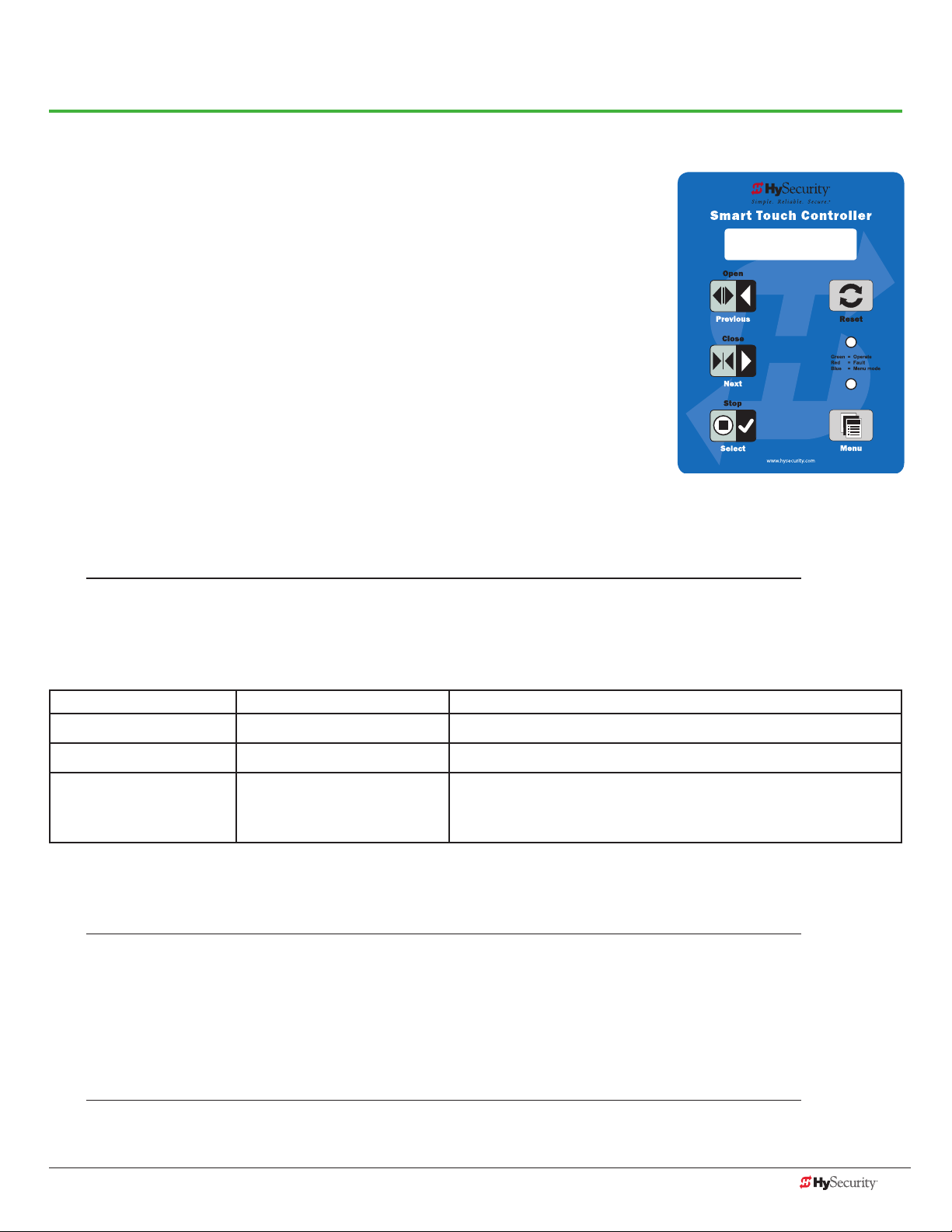
Troubleshooting
The Smart Touch Controller reports system malfunctions using three simultaneously occurring methods:
• Codes presented on its display (alert, fault or error)
• Activation of a buzzer which emits a series of chirps at dened intervals
• Stop gate travel
Refer to Troubleshooting Codes: Table 3 on page 74 for details concerning
identication and description of Alerts, Faults and Errors.
To help in diagnosing a controller board problem, the active status of each
input on the Smart Touch Controller is indicated by its associated LED.
• On AC-powered gate Operators: Active-input LEDs are always
illuminated.
• On DC-powered gate Operators (with AC input OFF): Press and hold
the Tact button to illuminate the active-input LEDs.
NOTE: A qualied technician may troubleshoot the operator with the aid of the information and procedures
that follow. If it is necessary to call a distributor for assistance, be sure to have the model and serial numbers
available. Other helpful information is the job name, approximate installation date, and service records of any
recently-performed maintenance work.
ALERT 22
INTLOCK FAILURE
sYstem dIagnostIC messages
Code Priority How to clear
ALERT Low Enter new command such as Open or Close.
FAULT Medium Press the Stop or Reset button
High
ERROR
NOTE: The green LED near the coin-sized battery on the Smart Touch Controller is the “heartbeat” of the
processor. This LED ashes continuously and at a constant rate when the system is operating normally. When
a fault, error, or alert occurs, it turns red.
Serious issue that may require
technical service.
The Smart Touch Controller maintains self-diagnostics. Specic codes appear on the display and the Audio Alert
buzzer emits distinctive chirping sounds. Any Alert, Fault, or Error is logged into memory and stamped with the
date and time. These diagnostic messages can be retrieved for analysis purposes via optional S.T.A.R.T. software
and a PC laptop.
NOTE: S.T.A.R.T. conguration and diagnostic software is available at no charge from www.hysecurity.com.
Errors can only be cleared by pushing the Reset button
or cycling power.
www.hysecurity.com Troubleshooting D0559 Rev. A 73
Page 82

Troubleshooting Codes: Table 3
Type Alert/Fault/Error Display Buzzer Chirp Sequence Possible Cause & Suggested Corrective Action
ALERT HYSECURITY
ENTRAPMENT MODE
2 chirps per second every
2s while control input is
active
An emergency close with constant hold or an emergency open
has caused the entrapment code to appear. When a command
of this nature is received, the operator stops and moves into
ENTR mode. Clear the code and return to run mode operation,
by pressing the Reset button.
ALERT HYSECURITY
SAFE MODE
ALERT LOW 24VDC
DC BUSS < 21V
ALERT CRITICAL LOW POWER No chirps: LCD steady and
ALERT DEAD BATTERY
DC BUSS < 21V
ALERT NO AC POWER Chirps once whenever the
ALERT ALERT 1
FORCED OPEN
2 chirps once when in Safe
Mode
No chirps; LCD ashes for
1s every 5s
controls disabled
3 chirps upon any
operating command entry
gate reaches the close
limit
2 pulses per second for
30s
An gate “edge” has been tripped or the operator has exited
entrapment mode. Refer to the description above.
NOTE: Gate will operate, if it receives a RUN command.
Only occurs in DC powered operators.
The system monitors the 24V control voltage in lieu of line
voltage. Low incoming line voltage will cause low control
voltage. Verify that the control transformer is connected
properly, (white – not used, red for 208V, orange for 230V and
blue for 460 V). Refer to Control Transformer Connections (Non-
UPS) on page 21. Check the line voltage, as the motor starts,
with a meter that has min/max hold capability. If the line voltage
drops more than 10% below nominal (187 on 208 VAC, 207 on
230 VAC, or 416 on 460 VAC) the voltage is dropping too much
and must be corrected. Generally, this requires larger wire size.
On 3-Phase operators, check each leg of to ground to make
sure it is balanced.
If the line voltage is not dropping below these limits, check the
24V AC and DC power at the power supply. Voltages less than
20V indicate an overloaded or failing transformer or power
supply board. Remove the loads until the fault is found.
DC operators only. Appears when the 24 VDC power drops too
low, disabling the operator to prevent damage to the batteries
from excessive discharge. Verify the AC power is present at the
charger, the charger is on and charging (Red LED is illuminated).
The charger should shut off (Green LED) when the batteries
charge to 29.0 VDC. If the batteries will not “hold a charge”
replace them.
AC power is shut off at the source (breaker) or is not connected.
The AC power switch on the operator (lower rocker switch) is
turned off, or the circuit breaker on the operator has tripped.
• Have a licened electrician check the wiring.
• Connect AC power to the operator.
• Reset circuit breaker at the electrical panel.
• Reset the operator circuit breaker.
• Turn AC power switch on.
Set FA 1 in the User Menu, to enable this option. The operator
will attempt to re-close itself if forced off the close limit switch,
the buzzer sounds for 30 seconds. Check for attempted
unauthorized access, external pressure trying to open the M30/
M50 gate or a mis-adjusted/failed closed limit switch.
74 D0559 Rev. A SlideDriver/SlideDriver 50VF Series www.hysecurity.com
Page 83

Type Alert/Fault/Error Display Buzzer Chirp Sequence Possible Cause & Suggested Corrective Action
ALERT ALERT 2
DRIFT CLOSED
ALERT ALERT 3
EXCESS DRIFT
ALERT ALERT 4
THERMAL OVERLOAD
ALERT ALERT 5
BOTH LIM ACTIVE
ALERT ALERT 6
LIM NOT RELEASED
ALERT ALERT 7
FREQ SHIFT FAULT
ALERT ALERT 8
LOOP SHORTED
ALERT ALERT 9
LOOP OPEN
ALERT ALERT 10
I2C BUS ERROR
ALERT ALERT 11
DETECTOR FAULT
ALERT ALERT 12
ON TOO LONG
2 pulses per second for 10
seconds
Gate drift in transit -
Advisory only. The alert
apperas and is being
prevented from re-
opening.
2 chirps per second every
15 seconds
2 chirps per second every
15 seconds
2 chirps per second every
15 seconds
2 chirps per second every
15 seconds
2 chirps per second every
15 seconds
2 chirps per second every
15 seconds
2 chirps per second every
15 seconds
2 chirps per second every
15 seconds
2 chirps per second every
15 seconds
Set F01 in the User Menu, to enable this option. If a M30/M50
gate should begin to drift closed it automatically reopens (for
up to 4s) once it leaves the full open limit. If it is not back on
the open limit at the end of 4s, an audible alert occurs. Check
for cylinder leakage, misadjusted/failed open limit, misadjusted
brake valve, outside pressure (wind, fallen trees) trying to force
the M30/M50 gate closed.
Will self-clear after an open or close input.
The motor windings have exceeded a preset temperature
generally due to excessive current. Verify:
• The motor connections are correct for the supply voltage
• Running voltage is within 10% of rated
• High starting currents last 2 seconds or less; if not and
voltage during start is correct, on 1Ø units you can replace
the start switch/capacitor
• Motor running current (all phases) is at or below rated ( at
normal pressures)
• When the motor is cool, open the motor connection box,
disconnect the 2 small wires going into the motor, and use
an ohmmeter to check continuity of these wires. They should
be a short circuit; if not, replace the motor.
The STC is seeing both limits tripped at the same time. Reset
the limits through the Installer Menu’s Learn Limits reset.
Is the pump developing pressure? Are the brake valves set
properly? Is there hardware holding the gate?
Check uid levels and brake value settings.
HY-5A detector has detected a frequency change outside the
normal range. Check the loops and the integrity of the loop
installation.
HY-5A detector has detected a short circuit in the loop.
Temporarily switch detector to be sure the loop is at fault and
then repair it.
HY-5A detector has sensed that the loop has become an open
circuit. Check all connections and/or use an ohmmeter to nd
out where the break is.
Communication issue between the HY-5A and the Smart
Touch Controller; reset and try again. Replace the HY-5A if the
problem continues.
Unknown fault; perform the megaohm test and x the loop if
necessary. Replace the HY-5A if the problem continues.
The detector believes there has been a vehicle on the loop for
greater than 5 minutes.
• Is there something metal on (or near) the loop?
• Is the sensitivity adjustment set too high?
• Is the roadway solid? If the underground loop moves it will
give false readings.
• There may be a problem with the loop itself. Check with a
megohm meter. New loops should read 100 mega-ohms
or better, between 50 and 100 operation are generally OK,
below 50 meg-ohms install a new loop.
www.hysecurity.com Troubleshooting D0559 Rev. A 75
Page 84

Type Alert/Fault/Error Display Buzzer Chirp Sequence Possible Cause & Suggested Corrective Action
ALERT ALERT 13
STIFF GATE
2 chirps per second every
15 seconds
The STC detects a gate that, over time, is requiring more power
to move it. Usually caused by degrading gate hardware or
debris in a slide gate track, this alert appears in the history log.
It does not affect opening or closing the gate.
• Check and correct gate hardware as required.
• Check motor brushes for excessive wear.
ALERT ALERT 14
STUCK GATE
ALERT ALERT 17
BAD COIN BATTERY
ALERT ALERT 18
CHANGE BATTERY
ALERT ALERT 19
FALSE SLOWDOWN
ALERT ALERT 20
EXT LOCK FAILED
ALERT ALERT 21
DRIVE TRIP
2 chirps per second every
15 seconds
2 chirps per second every
15 seconds
1 chirp a minute Batteries are not taking a charge properly. The STC has
2 chirps per second every
15 seconds
2 chirps per second every
15 seconds
2 chirps per second every
15 seconds
The STC detects that it cannot move the gate at all possible
caused by broken gate hardware or ice/snow buildup.
• Manually move the gate. Verify that it moves easily and is
unobstructed thoughout gate travel.
• Check and correct gate hardware, as required.
Replace the 3V coin battery that controls the internal clock, with
the AC power turned off. Use a CR2032 battery.
detected that the 24VDC UPS batteries need to be replaced.
NOTE: The buzzer will chirp every minute until the UPS
batteries are replaced.
Appears only on gate operators with VFD. Slowdown switch
tripped and released (less than 1 second) in middle of run.
Check for loose wires, limits and misaligned rails or limit ramps.
An interlock contact is closed, indicating that the M30 gate latch
(lock) is engaged, preventing the operator from starting. Check
the interlock and wiring.
M30/M50 gate travel will not occur until the alert is cleared. Any
open or close command resets the alert and starts the M30/
M50 gate moving, unless the VFD is experiencing a fatal error.
If you cannot clear the error alert by pressing the open or close
button, contact HySecurity.
ALERT ALERT 22
INTLOCK FAILURE
ALERT ALERT 24
EXT RELAY FAULT
2 chirps per second every
3 seconds
2 chirps per second every
15 seconds
Appears when the RS-485 communication connection is lost
for more than 5s between interlocked (dual gate) or sequenced
gate operators. Check cable connections and wiring. Make sure
both operators are working properly and have the same current
and up-to-date software versions. The alert auto clears when
communication between the two operators is restored. If the
operator on site is a singular gate and the display code ALERT
22 appears, access the Installer Menu. Verify the Installer Menu
items: DG (Dual gate) and SG (Sequential gate) are both set to
zero.
The Hy8Relay (extended relay module) is not being recognized.
Alert noted in diagnostic log.
Check the wiring:
• Make sure the slide switch on the side of the extended relay
module is set at “Normal.”
• (Y) Data + is connected to “A” DUAL GATE.
• (G) DATA - is connected to “B” DUAL GATE.
• Connector cable (4-pin) attaches to RS-485.
If the Hy8Relay module is not connected, access the Installer
Menu and check that the extended user relays are set to zero.
STC = R4 to RB (7-segment display)
SDC = R3 to R9 (16 character display)
STC = R4 to R11 (16 character display)
76 D0559 Rev. A SlideDriver/SlideDriver 50VF Series www.hysecurity.com
Page 85

Type Alert/Fault/Error Display Buzzer Chirp Sequence Possible Cause & Suggested Corrective Action
ELD
OOLD
IOLD
SLD
RLD
FAULT FAULT 1
FAULT FAULT 2
FAULT FAULT 3
FAULT FAULT 5
FAULT FAULT 14
ERROR ERROR 1
ERROR !ACTION BLOCKED
ERROR !ACTION BLOCKED
ERROR !ACTION BLOCKED
“Vehicle Loop Detectors” Appears in sequence with another display code which pertains
to the loop issue. Refer to the other display code for more
information. ELD = Exit Loop Detector
OOLD = Outside Obstruction Loop Detector
IOLD = Inside Obstruction Loop Detector
SLD = Shadow Loop Detector
RLD = Reset Loop Detector
MOTOR RUN TIME
PHOTO EYE
LOW VOLTAGE SAG
LIMIT FAILED
STUCK GATE
DIRECTION ERROR
PHOTO EYE CLOSE
PHOTO EYE OPEN
GATE EDGE
1 chirp once every
15 seconds
2 chirps per second once
per minute
2 chirps per second once
per minute
2 chirps per second once
per minute
2 chirps per second once
per minute
3 chirps per second once
per minute
1 chirp indicating that
the command cannot be
intiated
1 chirp indicating that
the command cannot be
intiated
1 chirp indicating that
the command cannot be
intiated
The STC has detected the motor is on longer than
the maximum run time selected. Should not occur in
StrongArmPark.
• Check and replace drive belt.
• Increase Max Run Timer in the Installer Menu.
Not applicable to StrongArm M30/M50.
“Monitored” means the STC must see the photo-eye NC
contact change from closed to open and back to close after
receiving the command to move, but before starting. (FAL2
indicates the Smart Touch did not see this sequence at start.)
Be sure the photo-eye is capable of, and set to provide this
function. Be sure the eye “common” wire is wired properly to
the “Photo Eye Power 24V Common” Terminal and Installer
Menu Item 18 (PEO/PEC-NO/NC) is set to 1.
The 24V control voltage is monitored in lieu of line voltage. Low
incoming line voltage will cause low control voltage. Verify that
the control transformer is connected properly, (white – not used,
red for 208V, orange for 230V and blue for 460V). Check the
line voltage as the motor starts with a meter that has min/max
hold capability. If the line voltage drops more than 10% below
nominal (187 on 208VAC, 207 on 230VAC, or 416 on 460VAC)
the voltage is dropping too low and must be corrected. This
condition is often caused by loose connections or power wiring
which is too small. If the wire is too small, it must be replaced.
SD50VF only. Not applicable for StrongArm M30/M50.
The STC has tried 3 times to overcome a stuck gate/arm. The
gate/arm is non-operational while this fault is triggered. Caused
by brokecn gate/arm hardware or ice/snow buildup.
• Check and correct gate hardware as required.
• Press RESET to clear fault.
Close Limit tripped after running Open or Open Limit tripped
after running Closed. Assess cables and wire connections.
Make sure wires are connected to the proper terminals.
Operator received command to run, but movement is
prevented. Photo eye is blocked or battery is dead. Clear photo
eye path and realign photo eye. Replace photo eye battery if
needed.
Operator received command to run open, but movement is
prevented. Photo eye is blocked or battery is dead. Clear photo
eye path and realign photo eye. Replace photo eye battery if
needed.
Operator received command to run open, but movement is
prevented. Gate edge blocked or disconnected and causes
operator to enter SAFE mode.
www.hysecurity.com Troubleshooting D0559 Rev. A 77
Page 86

Type Alert/Fault/Error Display Buzzer Chirp Sequence Possible Cause & Suggested Corrective Action
ERROR ERROR 2
IES DISCONNECT
ERROR ERROR 3
HY5A COMM ERROR
ERROR ERROR 4
DUAL GATE
ERROR ERROR 6
DRIVE BOARD
ERROR ERROR 7
MENU CHECKSUM
ERROR ERROR 8
RPM SENSOR
ERROR ERROR 9
BATT DISCONNECT
ERROR
FAIL FAIL
ERROR 10
SLOWDOWN SWITCH
PROGRAM DATA ERR
3 chirps per second once
per minute
3 chirps per second once
per minute
3 chirps per second once
per minute
3 chirps per second once
per minute
3 chirps per second once
per minute
3 chirps per second once
per minute
3 chirps per second once
per minute
3 chirps per second once
per minute
3 chirps per second once
per minute
The IES sensor could be bad, check to see that the N.C. contact
is intact. Check that you have the most current sensor; visit our
website and view the technical bulletins in the Tech Support
area. The sensor wire could be loose; you may want to tighten
the female connectors with some pliers. The software may
need to be updated. Make sure the brake valves aren’t set too
tightly by asking, “How fast does the gate panel stop when the
limit switch is tripped?” (Tight brake valves will raise the system
pressure.)
One or more detectors are not communicating properly.
Remove detectors, reset the controller, and re-install detectors
one at a time until faulty detector or loop is found.
Indicates a problem with the communication between the two
crash gate operators of a Primary/Secondary Set. The software
versions of these two operators must be the same. Check the
version by cycling the power off and on to each operator. On
power up the software version will ash on the screen (example:
v4.23). Make sure the conductors are twisted and shielded.
Beware of buried high voltage conductors that are too near to
the interconnecting conductors, they may interfere. Be sure the
parameter (DG) in the installer menu is set to 2 in the Primary
and 1 in the Secondary unit. Error automatically clears when
communication fault is resolved.
Internal error between the STC board and the VFD. Check
cable connections and wiring. Make sure both units are working
properly.
Contact HySecurity.
Check wiring from the hydraulic cylinder to the STC.
Only applies to DC Power Supply connection. Contact
HySecurity.
VFD only. The operator tripped the fully Open or CLose limit
before the Slowdown limit tripped. Check:
• Slowdown limit wiring and adjustment
• Adjustment of the limit ramps to verify that the limit switch
is being tripped. Manually trip the slowdown limit. OPEN
SLOWDOWN or CLOSE SLOWDOWN should appear on the
display which indicates that it is working properly.
1. Try turning off the power to the operator and having the
customer re-seat all of the various connectors and cables.
2. Upload the latest software release. If the fail does not go
away, Replace the STC board.
78 D0559 Rev. A SlideDriver/SlideDriver 50VF Series www.hysecurity.com
Page 87

eleCtrICal Issues
A general set of troubleshooting procedures are provided in the following paragraphs. Use a voltmeter to take
the measurements described in the steps. If at any point in the process, a result different than what’s expected
occurs, stop and identify the problem.
AC-Powered Gate Operators
PROBLEM 1: Pushed the OPEN and CLOSE button, but the motor is not running.
1. Verify the incoming voltage and phase at the incoming power terminals matches the voltage and phase on the
nameplate of the motor. They must match!
2. Verify the 24VAC transformer has the proper connection to the incoming power (the black wire is always connected);
White – 115VAC*, Red = 208VAC, Orange = 230VAC, Blue = 480VAC.
*NOTE: The white transformer wire is not used on SlideDriver 50VF-series operator.
3. Verify the primary tap wires match line voltage connected to operator. Measure the line voltage carefully to
distinguish between 208V and 230V branch circuits or between 390V and 460V branch circuits. A label on top of the
transformer identies the various voltage taps. This connection must match the voltage on the operator nameplate.
NOTE: Primary taps do not exist on battery operators.
4. Verify the 24VAC is present at the Red and Green wires from the control transformer to the Power Module by
measuring the bottom of the power supply board at the -ACC+ connectors.
5. Verify that the main power wires are at least the minimum wire size specied in the Wire Sizing and Runs on
page 16. Be certain that the branch circuit wire size versus the distance of the run from the main panel is large
enough to avoid excess voltage drop.
6. Verify 24VDC power is present on the Power Module between the +24VDC terminals above the terminal strip and
any screw connection on the terminal strip.
7. Be sure a 20A circuit (protected with a 20A inverse time breaker) is provided.
8. Check and make sure the operator is electrically grounded per NEC Article 250 and local codes.
9. Verify the 24VDC is present at the +24VDC and common terminals located along the lower edge of the Smart Touch
Controller board. (RADIO OPTIONS, etc.)
10. Verify that the “Heart Beat” LED is blinking green.
11. Verify the display is operational on the LCD and VFD display.
12. With the knowledge that the power is correct and the electric motor runs, check the STC display. If an error, alert or
fault code appears, refer to Troubleshooting Codes: Table 3 on page 74 to determine possible resolutions.
www.hysecurity.com Troubleshooting D0559 Rev. A 79
Page 88

meCHanICal Issues
CAUTION
General problems concerning gate movement can usually be resolved by using the hand pump and manually
moving the gate open and close.
General maintenance recommends scheduled inspection of all fasteners to make sure they are tightened securely
and torqued to proper specications. For torque specs, refer to General Maintenance.
HYdraulIC Issues
The speed at which the operator moves the gate is determined by the size of the hydraulic pump and software
settings.
Attempting to slow gate speed by changing a valve setting will cause inefciency and increased heating of the
hydraulic system, which will degrade system performance and also may result in premature system failure.
NOTE: If the gate speed must be changed, contact your HySecurity distributor or HySecurity Tech Support.
Extremely cold weather is unlikely to seriously affect the gate speed because HySecurity employs a special grade
of hydraulic uid (Uniow), which maintains a linear viscosity over a broad temperature range. This high quality
uid, combined with other design considerations, allows HySecurity to rate its operators for service in ambient
temperatures of -40°F to 158°F (-40°C to 70°C).
If the gate speed of your operator has been affected by cold weather, perform the following:
1. Verify the gate hardware is not impaired by ice.
2. Verify that the reservoir is lled with Uniow uid.
NOTE: Consider adding a heater in extreme cold weather regions. A biodegradable uid option does exist, but
it does not have the same uid viscosity at extremely low temperatures. The biodegradable uid option has a
temperature rating between -10°F and 158°F (-23°C and 70°C).
80 D0559 Rev. A SlideDriver/SlideDriver 50VF Series www.hysecurity.com
Page 89

tYpICal proBlems and trouBlesHootIng proCedures
A few typical problems and their associated troubleshooting procedures are provided to facilitate identication
and resolution.
PROBLEM 1: Pressing the Open and Close buttons produce no response (nothing happens).
1. Verify the line voltage is present and matches the operator’s input voltage requirement + 10%.
2. Verify the control voltage is present at the Power Supply Common and 24VDC terminals. It may be necessary to
reset the circuit breaker (black button) on the transformer.
3. If an external Stop button is not used, verify a jumper wire connects Common to Stop.
4. Verify there are no Faults or Errors being reported on the LCD display.
5. Jump COM to the OPEN or CLOSE INPUT and verify that the LED lights on the STC board which indicates that the
input is active and working properly. To help in diagnosing the problem, take note of what other inputs light up and
check the display for codes.
PROBLEM 2: Hydraulic pump is running and the hydraulic pressure is between 0 - 700 PSI, but the gate is not moving.
The Smart Touch Controller reports system malfunctions on its LCD display and the buzzer will emit a series of chirps at
dened intervals. Review the table of Alerts, Faults and Errors listed in System Diagnostic Messages on page 73. To
check the status of all inputs on the terminal strip, the LED tact button must be pushed.
If the power is three-phase, verify counter-clockwise Electric Motor rotation. To reverse rotational direction, switch any
two AC lines.
NOTE: The VFD Motor Controller displays trip and fault codes. Check to see if any error codes appear on the VFD
display. Most VFD issues are resolved through the STC software and modbus interface.
1. Check the hydraulic uid level by removing the plug in the pump reservoir. If necessary, add uid at this location
until the level is about ½ inch below the ller hole.
2. Unplug the hydraulic hoses and run the pump; if the pressure is low, adjust the Pressure Relief Valve.
3. If the Pressure Gauge does not respond to adjustment of the Pressure Relief Valve, completely remove the valve and
depress the plunger at the nose end with a blunt tool (e.g., an Allen wrench) and blow on it to remove any debris.
PROBLEM 3: The gate only opens or only closes.
1. Verify that no external device is commanding the gate to open or close by watching the LEDs associated with each
input.
2. If the gate only opens, the Directional Valve is probably stuck and needs to be checked for dbris and cleared.
3. If the gate only closes, the Directional Valve Coil is not being energized or is defective.
PROBLEM 4: A run command causes PEC to appear on display.
1. Check that the photo eye is not blocked. If it is, remove the blockage and realign the photo eye. Refer to Photo Eye
Alignment on page 64.
2. If you have a battery-powered photo eye, check that the batteries are viable and the batteries are fresh.
3. If needed, realign the photo eye. Refer to Photo Eye Alignment on page 64.
www.hysecurity.com Troubleshooting D0559 Rev. A 81
Page 90

82 D0559 Rev. A SlideDriver/SlideDriver 50VF Series www.hysecurity.com
Page 91
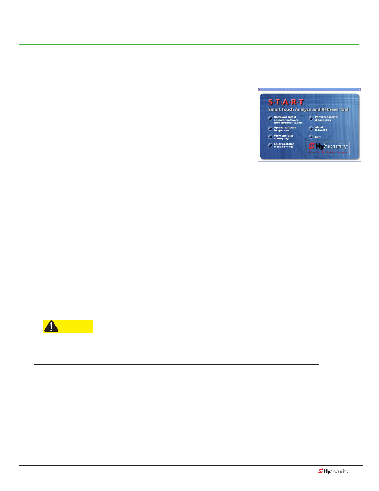
General Maintenance
CAUTION
smart touCH analYze and retrIeve tool (s.t.a.r.t.)
HySecurity provides Smart Touch Analyze and Retrieve Tool (S.T.A.R.T.)
software to help HySecurity gate operator users and installers conduct the
following eld service activities:
• Congure installer and user menu settings
• View the operator history (event) log
• Display monitored inputs for operator diagnostics
• Load Smart Touch Controller (STC) software
With S.T.A.R.T. software loaded on your laptop computer, you have an invaluable management tool for all
HySecurity operators. The RS-232 serial port (found on the Smart Touch Controller), allows you to download
system diagnostics and upload system congurations using the S.T.A.R.T. software. The free S.T.A.R.T. software is
conveniently located at www.hysecurity.com. Instructions for downloading S.T.A.R.T. are on the website.
What You Need
HySecurity Serial RS-232 communication cable with USB adapter and current USB driver.
• Laptop computer with Windows PC operating system (XP, Vista, Win7, or Win8)
• Minimum 128MB of RAM
• Minimum 5MB of hard drive disk space
• VGA graphics card (minimum resolution of 800 x 600)
Installing S.T.A.R.T. Software
Read the S.T.A.R.T. User Manual, and then take the following steps to download S.T.A.R.T. software:
The latest version of S.T.A.R.T. is encrypted. An error message will appear statng that the le is corrupt if you try
to load new operator code using out-dated S.T.A.R.T. software. Be sure to “uninstall” any outdated versions of
S.T.A.R.T. from your laptop and install the latestes version from www.hysecurity.com.
1. Bring up your web browser and type http://www.hysecurity.com in the command line.
2. Click Technical Support (left column) on the HySecurity home page.
3. Click Download: Smart Touch software.
4. Enter your user name and password. If you do not have a user name, register as an online member.
5. Click S.T.A.R.T. Software for Smart Touch and SmartDC to being the software download.
6. Read the End User License Agreement and, if you agree to the terms, click, “I accept” (bottom of page).
7. Save the START< >_setup.exe le to your desktop.
www.hysecurity.com General Maintenance D0559 Rev. A 83
Page 92

8. Double-click the le to begin the installation.
9. Click RUN. A setup window appears.
10. Follow the step-by-step instructions to complete the installation.*
11. When the download is complete, log off the HySecurity website. Shortcuts for the S.T.A.R.T. and
STC History Logs appear on your laptop’s desktop.
*NOTE: Conrm you have administrative rights by clicking the following on your computer screen:
Windows start ->Control Panel ->User Accounts ->User Accounts. See if your name appears as an administrator.
If you are the only user of a computer, you are by default the administrator. If not, you may need to consult with
your company’s system administrator prior to downloading the HySecurity S.T.A.R.T. program.
software maIntenanCe
The software on the STC board is periodically being enhanced with new features that create an easier install and
improve the on-board diagnostic tools. Be sure to check the HySecurity website for the latest version of software
and operator code before heading out for eld maintenance.
84 D0559 Rev. A SlideDriver/SlideDriver 50VF Series www.hysecurity.com
Page 93

eleCtrICal Controls
NOTICE: Before servicing, turn off all power switches.
No routine maintenance is needed for the electrical system or controls. If the environment is very sandy or dusty,
or has many insects, be certain to seal all holes in the electrical enclosure. Blow the dust out of the electric panel
with compressed air. Use the troubleshooting Table 3 on page 78 to assess and x error, alert, and fault codes. If it
is necessary to call a distributor for assistance, be sure to have your model and serial number ready. Other helpful
information includes the name of the job, approximate date of installation, and the service record of the operator,
especially if any work has been done recently.
Clock Battery Replacement
A lithium coin battery supports the clock, so the date and time is
retained even when the main power is turned off. Replace the battery
about every ve years (or as needed) with a DL 2025, DL 2032, or CR
2025, or CR 2032 battery.
Battery
meCHnICal Controls
Stopping the Gate
Most models (except SlideDriver 15 and 40) employ a time delay Soft Stop system.
Additionally, brake valves are used to control the stopping of heavy or fast moving
gates. These valves are exclusive to HySecurity operators. They are independently
adjustable to allow the gate to stop predictably and without banging.
Starting the Gate
To accommodate for loads moving beyond one foot per second, it is necessary to Soft
Start the load gently and stop it smoothly. HySecurity accomplishes Soft Start with
another exclusive feature we call an Accumulator With Out Gas (AWOG), which diverts
some of the start-up hydraulic ow, accommodates for the load, and starts the gate
smoothly, similar to letting your foot slowly off a car clutch without any lurching.
USER 3
STAT US
COM
NO
OUTSIDE
OBSTR
VEHICLE DETECTOR
The downward facing AWOG (shown right) improves the life and performance of a gate
system and never needs adjustment.
AWOG
www.hysecurity.com General Maintenance D0559 Rev. A 85
Page 94

meCHanICal maIntenanCe
NOTICE: Before checking the internal mechanisms of the operator, turn off all power switches.
The mechanical maintenance for the SlideDriver is not in depth or difcult, but should be performed on a
routine basis.
Schedule regular maintenance:
9 Check for signs of rust. The operator chassis is zinc plated which is corrosion-resistant, but some
environments may increase the rate of corrosion. If any areas of rust are found, reduce the spread of
corrosion by treating the areas with a rust inhibitor.
9 Grease the hydraulic cylinder every 50,000 cycles. Use NLGI #2 Grade Moly EP lithium base grease only
and apply it with a standard grease gun. Grease other bearings every 100,000 cycles.
9 Check the motor. DC motors contain carbon brushes which wear over time and must be replaced. Failure
to replace the brushes will result in damage to the DC motor. Brushes should be inspected every year in
high usage applications or every 100,000 cycles and replaced as needed.
9 Replace worn-out batteries. Refer to Clock Battery Replacement on page 85.
Drive Rail
Verify that the drive rail does not move more than 1-inch up and down or ¼-inch side-to-side throughout the
entire horizontal travel of the gate. Re-alignment is simple if the rail is mounted with U bolts. Adjusting the rail for
side-to-side movements requires inserting shims between the rail and the gate where necessary. To adjust sideto-side movements, loosen the U bolts and add or remove shim stock. To adjust up or down, loosen the U bolts
and simply tap the rail with a hammer until the
correct height is reached.
The height of the drive rail needs to be set
between 9½ to 10 inches (24 to 25 cm) from base
of SlideDriver chassis if using XtremeDrive™
wheels. For site planning, see “SlideDriver/
SlideDriver 50VF Site Installation Overview” on
page ii.
AdvanceDrive™ Wheel
Drive Rail (standard)
Rack
XtremeDrive™ Wheel
XtremeDrive™ System
86 D0559 Rev. A SlideDriver/SlideDriver 50VF Series www.hysecurity.com
Page 95

Drive Wheel Spring Tension (Adjustment of Manual Release)
WARNING
All SlideDriver operators come equipped with a toggle handle manual release mechanism to disengage the drive
wheels from the drive rail.
During shipment, a piece of Styrofoam is placed between the coupling nut and the chassis. If the packaging is
still in place, discard it.
When releasing the handle inside the chassis, be careful as the mechanism is spring-loaded and drops rapidly.
Hold the toggle handle appropriately so your ngers do not get pinched, hit, or crushed.
To disengage the drive wheels, simply pull the aluminum toggle handle down. As the lower drive wheel drops
and disengages from the drive rail, it causes the coupling nut on the threaded rod to drop to its lowest position
and push on the base of the operator. This causes the upper drive wheel to lift and disengage from the drive rail.
The coupling nut must be adjusted correctly so the wheels provide a strong clamping force on the drive rail. The
red spring should measure 2 to 2⅛-inch (5 to 5.5cm) in height when under the correct compression.
NOTE: If the drive rail is installed at the correct height to the chassis, the toggle release mechanism spreads both
wheels equally in relation to the drive rail. If the drive rail has been mounted higher than specied, it may be
necessary to use an additional coupling nut and ⅜” bolt which can extend beyond the all thread and create
additional lift clearance for the upper drive wheel when the toggle handle is released. If this extension method is
used, adjust the ⅜” bolt so the drive wheels spread equally when they are fully disengaged.
Drive rail slides
between drive
wheels
2 to 21/8 ”
(5 to 5.4 cm)
Toggle handle
Toggle handle
Drive wheels
Red spring controls
wheel grip
Coupling Nut
for spring tension
adjustment
www.hysecurity.com General Maintenance D0559 Rev. A 87
Page 96
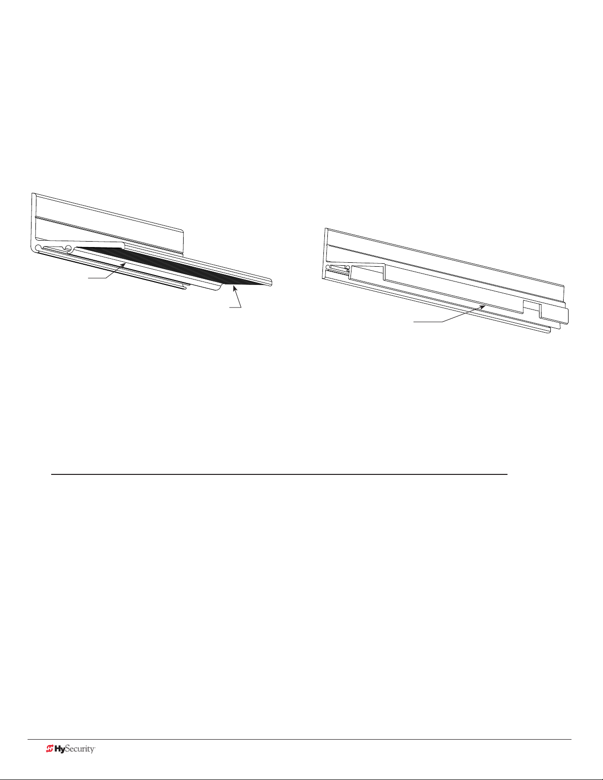
Grooved Drive Rail
The grooved drive rail has become the standard for all new SlideDriver gate operator installations.
In this manual, several illustrations show the non-grooved, anged drive rail which is no longer available unless a
Solenoid Lock option is installed.
The grooved drive rail replaces the non-grooved, anged drive rail.
A section of the two different drive rails is shown in the illustration.
Standard grooved drive rail Non-grooved, flanged drive rail
No anges
Grooves on the underside
NOTE: Solenoid Lock option
requires anged drive rail
Grooved versus non-grooved, flanged drive rail
The small grooves on the underside of the new drive rail improve traction in slick or wet conditions and provide
more pulling and stopping power in SlideDriver installations. The three underside anges have been eliminated
which reduces drive wheel wear and drag in misaligned gate installations. Additionally, the no-ange drive rail
stacks better for shipping which reduces the likelihood of freight damage.
NOTE: The grooved drive rail is standard and will be on your order unless you specify otherwise. The nongrooved, anged drive rail is still available for use with the Solenoid Lock option. The Solenoid Lock option
requires an outer edge ange and therefore must be installed with the non-grooved, anged drive rail.
88 D0559 Rev. A SlideDriver/SlideDriver 50VF Series www.hysecurity.com
Page 97

Drive Wheel Assembly
Drive wheel assembly tasks are slightly different depending on the type: AdvanceDrive™ or XtremeDrive™.
NOTE: Installation instructions are provided with the replacement drive wheels. However, a brief overview of the
drive wheel assembly is shown below.
Collared Drive Wheels AdvanceDrive Wheels
AdvanceDrive Wheels assembled AdvanceDrive and XtremeDrive Wheel combo
www.hysecurity.com General Maintenance D0559 Rev. A 89
Page 98

HYdraulIC sYstem maIntenanCe
Fluid Level: Under normal conditions, hydraulic systems do not consume uid. Check the system thoroughly for
leaks, before adding any uid. If uid needs to be added:
1. Remove the metal plug from the tank.
2. Use HySecurity Uniow hydraulic uid; part number
Brake Valves
MX000970. Gallon sold by our distributors.
3. Fill to within ½ inch of the plug level, and then replace plug.
NOTICE: Never use brake uid. It will severely damage the hydraulic
system. Use of any uid other than uid recommended by HySecurity
may void the operator warranty.
Brake Valves
Look for leaks: Occasionally there may be slight seeping at the
ttings after some usage. Tightening of the ttings usually corrects
the problem. If leaking persists, replace “O” rings, ttings or hoses,
if required. No further leaks should occur.
Quick
Disconnect
To Change Fluid: Unlike a gas engine, the uid inside a hydraulic
system does not foul, so uid changes do not need to occur often.
HySecurity recommends draining the reservoir and replacing the
uid at ve-year intervals. Fluid breakdown caused by heat is the
Pump
pack
main concern. If the unit is subjected to high use, or you are using
the HySecurity biodegradable uid option (especially in a wgate climate), change
the uid more frequently.
To change the hydraulic uid,
1. Remove the reservoir from the pump pack.
2. Completely empty it.
The Pressure Relief
Valve is located
behind the
motor on the
pump pack or
soft start
manifold.
Solenoid
Adjustment Screw
SlideDriver 15, 40, 50VF
Locknut
3. Wipe the reservoir clean and clean the derby screen.
4. Re-assemble the pump unit and rell it with new Uniow hydraulic uid.
Motor
5. To avoid overlling, slowly pour the uid through the ller port near the
reservoir’s top until the uid is within one inch of the port’s opening.
Pump
pack
6. Replace the plug and wipe up any spilled uid. Spilled uid dries to a
sticky and messy consistency.
Cold Weather Issues:
1. Check that your reservoir is lled with our Uniow high performance uid.
2. Excessive ice buildup can partially or totally jam gate operation. Operate the gate manually, while clearing
the ice buildup.
3. If the operator is located in an area of extreme snow conditions, regular maintenance to dig the operator
out may be required. A heater option may help.
NOTE: A biodegradable uid option does exist, but it does not have the same uid viscosity at extremely low
temperatures. Uniow uid temperature rating is between -40°F and 158°F (-40°C and 70°C). The biodegradable
uid has a temperature rating between -10°F and 158°F (-23°C and 70°C).
90 D0559 Rev. A SlideDriver/SlideDriver 50VF Series www.hysecurity.com
Page 99
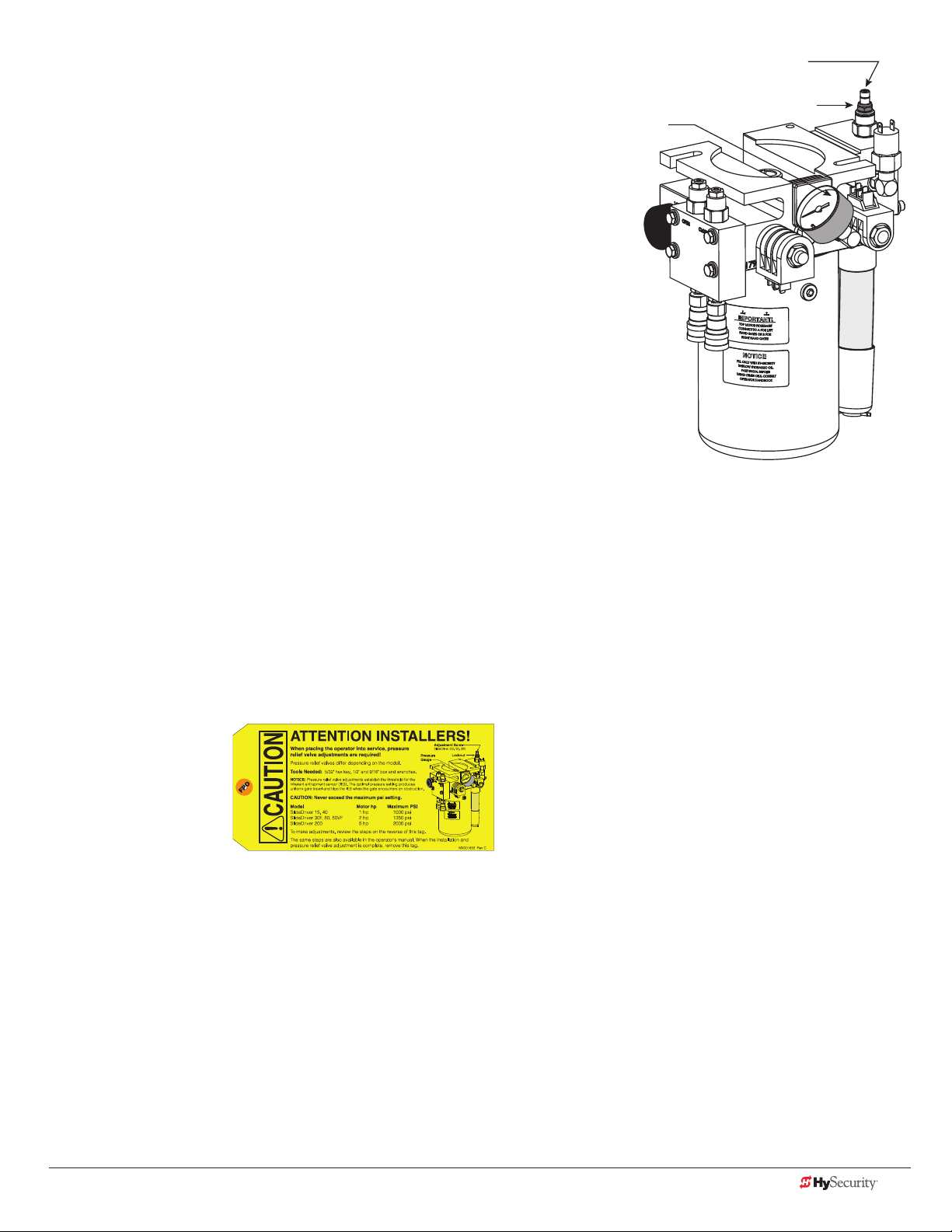
Brake Valve Adjustments
Proper adjustment of the brake valves is important for smooth operation
of the gate. The position and placement of the limit ramps on the drive rail
plays an important part on how the brake valves work.
In order for the brake valves to have time to function, the limit ramp must
trigger the limit switch at least two inches before the point at when you
want the gate to stop.
Adjustment of the brake valves, one for each direction of travel, will
determine how quickly the gate actually stops. If adjustment is needed,
loosen the 9/16-inch lock nut on the top of the brake valve and make
¼-inch incremental turns on the adjustment stem with a hex key.
Note that the adjustment screw varies depending on model type.
The adjustment is counter-intuitive.
A counter-clockwise adjustment stops the gate more rapidly. If the
adjustment is set too loose, the limit ramps will bang into the drive wheels.
If the adjustment is set too tight, the system pressure will increase, the
gate speed may decrease and the gate will jerk to a stop.
Pressure
Gauge
Adjustment Screw
SlideDriver 30F, 80, 200
Locknut
Brake valves are factory-set to midpoint, two turns. This should be sufcient for most applications. If the limit
switch triggers and the drive rail stops more than two inches into the limit ramp, increase braking. When the
adjustment is complete, retighten the locking nut to hold the setting.
Pressure Relief Valve Adjustments
The Pressure Relief Valve governs the maximum system hydraulic pressure. It is located on the backside of the
pump. The pressure relief valve is factory set and may need to be adjusted depending on the gate weight. See
“Adjusting the Pressure Relief Valve” on page 24 or refer to the yellow tag wire tied to the unit and follow the
instructions.
Open Valve
The open valve is solenoid operated and, when energized, directs the hydraulic ow to open the gate. No
adjustment of this valve is possible or necessary. The black solenoid coil mounts on its valve stem.
www.hysecurity.com General Maintenance D0559 Rev. A 91
Page 100

slIdedrIver operator maIntenanCe sCHedule
Name of part What to do Check at these recommended monthly intervals
1 3 6 12 24
Gate and hardware Check for damage and wear *1 X
Drive wheels Check for tightnes and wear *2 X
Wheel clamp spring Check for clamping tension *3 X
Stop limit switches Check for adjustment *4 X
Deceleration switches Check for adjustment *4 X
Anchor bolts Check for tightness X
Fluid level Check for loss of uid *5 X
Hydraulic uid Drain and replace uid X
Clock battery Replace *6 X
Motor Brushes (DC Only) Replace *7 X
Special Notes:
*1. Your gate and gate hardware will require more maintenance than your HySecurity operator. A damaged gate or worn hardware
may cause slow or erratic operation and will result in excess drive wheel wear. Lubricate gate hardware more frequently and
check for smooth operation by opening the toggle clamping mechanism and then pushing the gate manually. One person
should easily be able to push all but the largest of gates. Damaged or warped gate panels should be straightened or replaced.
*2. Normally, drive wheel life is many years. They are designed to avoid slipping on the rail. Wheels may be greatly shortened by
any of these faults: clamping spring not adjusted correctly, operator misaligned in relation to gate panel, badly warped gate
panel, extremely stiff gate hardware, and/or loose wheel mounting bolts (tighten to 25 ft. lb).
*3. Verify that the red clamping spring is compressed tightly so that drive wheels apply a strong grip on drive rail. The red spring
should normally be compressed to 2-inches in height. See 87.
*4. The limit switch and deceleration switch rollers should ride ¼ to ½-inch below the drive rail, near the center of the channel.
Maladjustment may result in false or early tripping or no limit function at the end of travel. Verify that the limit trip ramps are
tightly bolted to the drive rail.
*5. The uid level should remain no less than one inch below the ller hole. Refer to maintenance instructions for uid lling. Loss
of uid is not normal and indicates a leak that must be located and repaired. Use Uniow uid, part MX000970, if additional
uid is required.
*6. Replace the Smart Touch Controller coin battery with DL 2025 / DL 2032 or CR 2025 / CR 2032.
*7. DC Operators use DC motors with 4 carbon brushes which wear in normal operation. Worn brushes can damage the DC
motor. Under severe conditions HySecurity recommends that brushes be checked after 2 years or 250,000 cycles and the
replacement interval be adjusted as necessary.
92 D0559 Rev. A SlideDriver/SlideDriver 50VF Series www.hysecurity.com
 Loading...