

Page 1

Page 1
www.hysecurity.com © 2014 P/N MX3431 D0596 Rev A
Installation Instructions
MX3431
Smart DC Remote Power Supply
e HySecurity Smart DC Remote Power Supply provides an optional power
source for Smart DC gate operators that are congured for solar-power. e kit
converts high voltage AC power into low voltage DC power which eliminates the
need for solar panels. Low voltage wire is run out to the gate operator while the
power supply remains in garage or shed plugged into the AC power source.
NOTE: To install the Smart DC operator on site, follow the separate installation
instructions that accompany the gate operator.
To install the Smart DC Remote Power Supply, review the illustrations and the
steps found on the following pages.
Tools required
• Pliers for crimping
• Wire cutter
Power Cable and Wire Connections
Follow the steps to secure power connections. Wire size and appropriate distance
run to operator is shown in Table 1.
NOTE: The Smart DC Remote Power Supply must be located in a cool, dry location.
Examples include: Off the oor in a garage or inside a weather tight shed.
Table 1: Wire Size to Maximum Run
Wire size* Maximum Run
100% Duty Cycle
Maximum Run
50% Duty Cycle
Voltage Rating
for Direct Buried Cable
12 AWG 400 ft (122 m) 800 ft (244 m) 300V
14 AWG 250 ft (76 m) 500 ft (152 m) 300V
16 AWG 175 ft (53 m) 350 ft (107 m) 300V
*Other cable sizes not recommended.
12
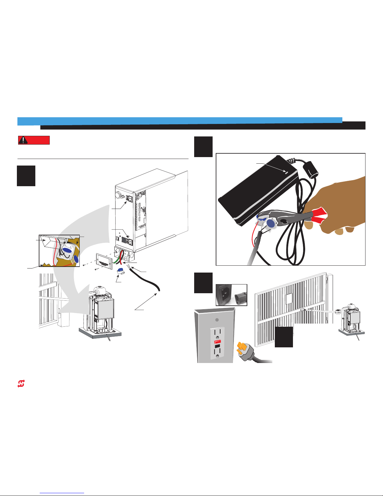
1
Run a “two conductor” power cable from the
Smart DC Remote Power Supply location to the
HySecurity Smart DC gate operator.
SwingSmart operator
shown as reference only.
Trench and install in-ground cable.
To protect cable wire, conduit is
recommended.
Output of power supply internally set to 48VDC.
No adjustment can be made.
Page 2
Page 2
www.hysecurity.com © 2013 P/N MX3431 D0596 Rev A
Technical Support
For technical support, call your installer or authorized HySecurity distributor.
Obtain the serial number of your operator before calling.
For the name of a distributor near you, call HySecurity at 800-321-9947.
12
2
12
3
24VDC
Connect wire leads to
junction box.
Insert the wires into the supplied
pig tail connector:
• Red wire from the junction box
with Positive wire lead coming
from the power cable
• Black wire from the junction
box with Negative wire lead
coming from the power cable
Crimp the pig tail using pliers as
shown in the photo.
In-ground power cable
Pig tail
connector
Junction box wires:
• Red wire to Positive lead
• Black wire to Negative lead
Make sure all power switches are in the OFF position. Follow all electrical code standards and
regulations.
DANGER
Connect in-ground power wire to Smart DC
Remote Power Supply.
Power cable return
to Smart DC Remote
power supply
12
4
Connect Smart DC Remote Power
Supply to AC power.
12
5
Turn ON Smart DC
gate operator.
When you plug the Smart DC Remote power
supply into an AC outlet, an LED illuminates
indicating power is available to the operator.
DC
motor &
battery
power
switch
Refer to the illustration in step 2.
• Turn ON the DC Motor & Battery
power switch rst. The display lights
indicating power is being supplied
through the batteries.
• Turn On the Solar Panel power switch.
In this case, it is connected to the
Smart DC Remote power supply.
LED illuminates when
AC power is supplied
Power supply wires:
• Red wire to
Positive wire lead
• Black wire to
Negative wire lead
coming from the
power cable
Power
source
switch
Chassis
base
Junction
box
Wires from
power supply
 Loading...