

HySecurity HydraSwing 40F, HydraSwing 40F Twin, HydraSwing 40, HydraSwing 40 Twin, HydraSwing 80F Installation Instructions Manual
...Page 1
MX3635-01
800-321-9947 www.hysecurity.com
Installation Instructions
MX3635-01 Rev. D
Linear actuators for large, heavy swing gates and swing gates subject to extreme peak winds
HydraSwing 80 & 150
HydraSwing 40s
Models
HydraSwing 40F
4,000 lb (1,814 kg) 10-15 seconds
HydraSwing 40 4,000 lb (1,814 kg) 15-20 seconds
HydraSwing 40 Twin 4,000 lb (1,814 kg)/leaf 15-20 seconds
HydraSwing 40F Twin 4,000 lb (1,814 kg)/leaf 10-15 seconds
HydraSwing 80F 8,000 lb (3,629 kg) 15-25 seconds
HydraSwing 150 15,000 lb (6.804 kg) 20-30 seconds
Page 2
© 2017 www.hysecurity.com HydraSwing Installation and Assembly MX3635-01 Rev. D Page 2
Read & Plan
Read and follow the Important Safety Information provided in the Programming and
Operations Manual prior to installing the HydraSwing. Read and follow these installation
instructions and make sure to conform to site specications and all local and federal
regulations and codes.
30⅝” (78 cm)
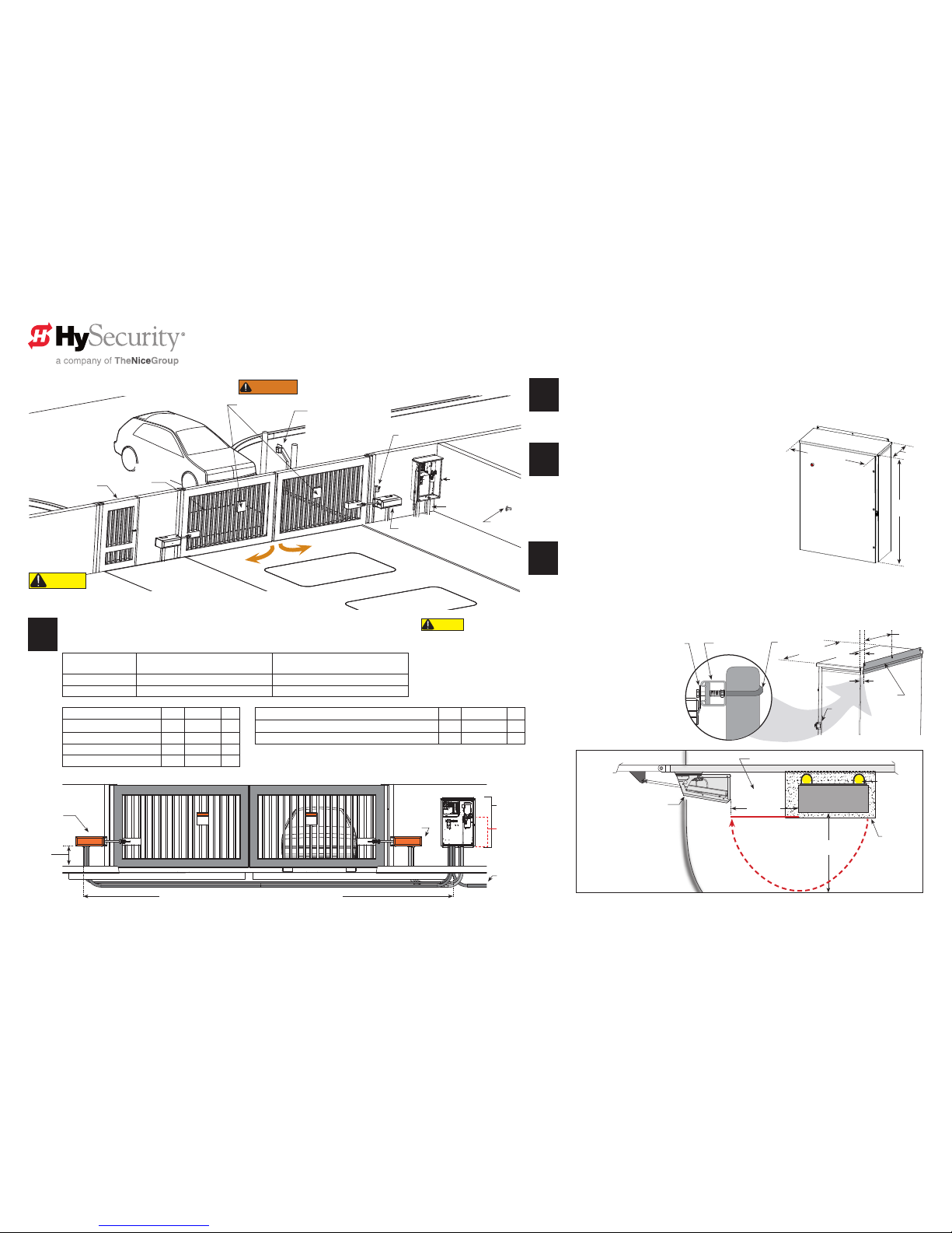
HydraSwing: Plan Site Design
1
2
Measure and Calculate
Pay attention to gate swing (retracted or extended
cylinder) and clearance around the mounting location.
Consider right handing and left handing. Allow for
access to brake valves.
Use the charts, provided on pages 3 and 4, to
determine gate geometry and placement of the chassis
and gate mount.
HydraSupply
Reector
Key or card reader
Mount access control
devices at least 6 ft (183 cm)
beyond gate.
Pedestrian gate
HydraSwing
Warning Signs
Shadow Loop
Inside Obstruction Loop
or Free Exit
Outside
Obstruction
Loop
3
Design Vehicle Loops
If automatic close is desired for a uni- or bi-directional
gate, a SHADOW and one other loop (IOLD or OOLD) is required.
Three loops are preferred: SHADOW, IOLD, OOLD (Free Exit, optional)
NOTE: Loop layout is dependent on uni- or bi-directional trafc and length of gate and width
of roadway. Vehicle must move from one loop to the next without loss of detection. The site
design shown on this page is for illustrative purposes only.
NOTE: Pay attention to
and plan for clearance
and access.
4
Install conduit for communication and power
Locate and install the HydraSupply within 50 feet (6.1 m) of the HydraSwing gate operator.
NOTE: Order hose through HySecurity. See CAUTION.
Hose length in feet
(Total Run)
Hose Diameter: Model 40 & 40F, Twin Hose Diameter: Model 80F & Model 150
0 to 50 ft 1/4 inch 3/8 inch
50 to 100 ft 3/8 inch 1/2 inch*
Minimum conduit required No. Min. Size cm
3/8 inch Hydraulic hoses* 1 2 inch 5
1/2 inch Hydraulic hoses* 1 3 inch 7.6
Sensor wire to operator 1 3/4 inch 2
AC Main power 1 1 inch 2.5
Conduit
Addt’l conduit may be ordered and used for: No. Min. Size cm
Bi-parting gate connection for low voltage wiring 1 1 inch 2.5
Heater or Emergency Release options 2 3/4 inch 2
HydraSupply Cabinet
Concrete pad
Shown
Post-mounted.
Roadway
Gate
Secure base plate with anchor
bolts. See NOTE regarding
bolt sizes on page 3.
HydraSwing 80F & 150 chassis
dimensions: 41”L x 20½” W
(104 x 52 cm) optional base
extension adds an additional
4” to the width
HydraSwing 40 & 40F chassis
dimensions: 27” L x 13” W
(69 x 33 cm)
Conduit runs between HydraSwing and cabinet.
NOTE: Design shown for illustrative purposes only.
Drawings are NOT TO SCALE.
WARNING
Be sure to place the WARNING signs on the gate. For your
records, take a photograph of the completed installation site.
Wall
36” (91 cm)
minimum
36” (91 cm)
Door swing
Photo eye
Left handing
Right handing
12⅝”
(32 cm)
42⅜”
(107 cm)
HydraSupply
Cabinet
*NOTE: HydraSwing orders include two (2) uid-charged hoses and attached ttings totaling up to 50 ft (15 m).
Additional hose is billed by the foot. For HydraSwing 80F and 150, use 1/2-inch hose and ttings where the
HydraSupply cabinet is installed more than 50 ft from the actuator AND temperatures routinely fall below 0°F.
For distances between the HydraSupply and actuator longer than 100 ft (30 m), contact Tech Support.
HydraSwing
Left
handing
Incoming power
HydraSupply Cabinet
Inches: 30⅝W x 42⅜H x 12⅝D
Centimeters: 78W x 107H x 32D
Additional Hose
estimate
HydraSwing
Right
handing
HydraSupply
HydraSwing Bi-parting Gate
Maximum 50 foot run (15 m). See Hose Diameter chart above.
12 inches
(30 cm)
minimum
clearance from
grade
HydraSupply Cabinet
Wall or post-mount the
HydraSupply cabinet.
If planning a post mount, mounting
holes need to be drilled (U-bolts,
fasteners, and unistrut are not
provided). Cabinet may also be wallmounted with anchor bolts.
NOTE: The mounting holes on the
top and bottom anges are 5/16-
inch diameter.
13½”
(34 cm)
1⅞”
(5 cm)
1¼”
(3 cm)
Door clip
C
/
L
C
/
L
Flange
Flange Unistrut
U-bolt
30¾” (78 cm)
CAUTION
Remember to order hose through HySecurity!
In addition to conduit length, make sure
to measure hose requirements inside the
HydraSwing and HydraSupply. For example,
HydraSwing 80F requires about 1 ft of
additional hose length inside the operator
and another 2 or 3 ft inside the HydraSupply.
For proper sequencing of bi-parting (dual) gate systems, it is critical that the hydraulic
cylinder be fully extended. See “Determine Arm Geometry: 40 & 40F” on page 4.
CAUTION
Page 3
© 2017 www.hysecurity.com HydraSwing Installation and Assembly MX3635-01 Rev. D Page 3
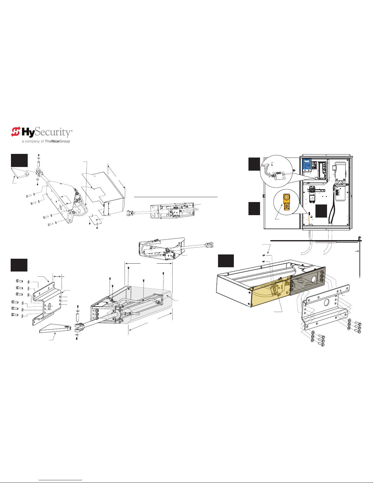
Assembly: Exploded Views
Optional base extension
provides 4” offset for 80F
or 150 models.
HydraSwing: Model 40 and 40F
HydraSwing: Model 80F and 150
Nuts and washers (6x)
secure optional base
extension.
Remove 2 phillips-head screws to move
brake manifold and provide access to
mounting holes on the HydraSwing chassis.
Remove 5 fasteners on the
top panel to access interior
of HydraSwing. Tamper
proof screws require TX40
drive bit (included).
1a
1c
2
1b
1. Assemble and secure chassis to mounting surface.*
2. Feed hoses through conduit and connect them to the QD ttings
(quick disconnects).
3. Ground the gate operator.
4. Feed sensor wire through conduit to HydraSupply and connect it
to the 4-pin receiver board.
*NOTE: Refer to Arm Geometry, on pages 3 and 4, for mounting
dimensions and requirements.
Gate
mount**
Access cover
plate (for conduit
and hoses)
3
4
Conduit
HydraSwing: Model 80F and 150
Move the brake manifold to mount the
HydraSwing chassis whether you use the
optional base extension or not.
Two hoses connect to QDs (quick
disconnects) on the hoses fed through
conduit from the HydraSupply
Drawings NOT to Scale
HydraSwing 40 & 40F
Right handing
HydraSwing 40 & 40F
Left handing
Brake valve
location
Brake valve
location
**NOTE: Depending on whether the chassis is mounted
recessed or elevated, you will need to modify the gate mount
to accommodate the gate geometry.
20½” (52 cm)
Additional 4” for
the optional base
extension
4” (10 cm)
41” (104 cm)
HydraSwing 80F & 150 chassis dimensions:
41”L x 20½” W (104 x 52 cm) optional base extension adds an additional 4 inches to the width
HydraSwing 40 & 40F chassis dimensions:
27” L x 13” W (69 x 33 cm)
27” (69 cm)
13”
(33 cm)
Base extension
(option)
Base extension
(option)
NOTE: Anchor bolts for 80F and 150.
5/8-inch, Grade 8.
Minimum 4 bolts required for steel to steel mount.
Anchoring to concrete is dependent on concrete
strength. Before installing, consult a structural engineer.
NOTE: Anchor bolts for 40 and 40F.
1/2-inch, Grade 8. Minimum 4 bolts
required for steel to steel mount.
Anchoring to concrete is
dependent on concrete
strength. Before installing,
consult a structural engineer.
.....
4-pin sensor
wire connector
Earth ground
Ground rod
NOTE: Outswing gate mount
requires customer fabrication.
See pages 4 and 5.
Page 4

© 2017 www.hysecurity.com HydraSwing Installation and Assembly MX3635-01 Rev. D Page 4
Determine Arm Geometry: 40 & 40F
90° Opening
95° Opening
100° Opening
Inswing Closed Position:
Center hinge
Gate Opening and Gate Geometry: Outswing
Degree of Swing Xf Xg Yg
90 8” (20 cm) 5¼” (13.3 cm) 8½” (21.6 cm)
95 8¼” (21 cm) 5⅝” (14.3 cm) 7½” (19 cm)
100 8⅝” (22 cm) 6” (15.2 cm) 6¾” (17.1 cm)
Gate Opening and Gate Geometry:
Inswing
Degree
of Swing
Xf Xg Yg
90
8”
(20 cm)
8¼”
(21 cm)
5¼”
(13.3 cm)
95
8¼”
(21 cm)
8”
(20 cm)
5”
(12.7 cm)
100
8⅝”
(22 cm)
7¾”
(19.7 cm)
4¾”
(12 cm)
Open Position = R
“Retracted”
in the Installer Menu
Gate
Gate mount
Cylinder rod
Gate swing OPEN
Drawings NOT to Scale
Open Position = E
“Extended”
in the Installer Menu
Outswing Open Position: Center hinge
Cylinder rod
NOTE: Outswing gate
mount requires customer
fabrication.
90° Opening
95° Opening
100° Opening
Shadow Loop
Entering vehicle
Access control
HydraSupply
Photo eye
Gate swing
OPEN
34½” (88 cm)
minimum
Hinge centerline
Xg
Mounting Surface: Shimmed, Flush, or Inset
If Yf dimension is between Then use Cylinder Position
2¾” to 3¾” (7 to 9.5 cm) 1
1 to 2” (2.5 to 5 cm) 2
0 ± ½” (0 ± 1.3 cm) 3
13”
(33 cm)
2
1
Photo eye
Roadway edge
C
/
L
Xg Xf
5”
(13cm)
14”
(35cm)
24”
(61cm)
5”
(13cm)
Yg
C
/
L
C
/
L
C
/
L
Yf
Hinge
centerline
Mounting Surface
Dashed lines:
Indicate mounting
hole centerlines
Gate
Overhead View: Model 40 and 40F
Gate hinge
centerline
NOTE: Use the Mounting
Surface chart to determine
the best position for the
cylinder. Round up and
shim to meet Yf dimension
requirements.
Inswing mount shown: Center hinge
C
/
L
Yg
C
/
L
Inline hinge example
Xg Xf
Cylinder Position 3
Flush mount or slightly inset
C
/
L
C
/
L
Mounting surface
Gate
Cylinder Position 1
Cylinder Position 2
Cylinder Position 3
Mounting holes shared with
brake cylinder bracket
Position 3
Cut out view
Conduit
cover (2x)
Brake manifold
CAUTION
Use the measurements for your gate type:
Inswing or Outswing.
Measure and cut (or shim) gate mount to meet
the Yg requirement. Fasten the gate mount to the
cylinder to meet the Xg requirement. Tack weld until
hoses available or the accuracy of the dimensions
are conrmed. The gate mount and cylinder need to
remain in a horizontal plane throughout gate travel.
If any vertical movement occurs, the load on the
cylinder is strained and will lessen its life and void the
Warranty.
Torque fasteners to
70 ft-lbs
Discard washers and
lock nuts if using
Cylinder Position 3
Cut or shim along mounting edge
depending on your gate arm
geometry. Refer to tables for Yg
and Xg measurements.
Gate mount:
6½ inch dimension
Cylinder end head with swivel
Three cylinder positions adjust for the differences in
surface mounting requirements: shimmed, ush, or
inset (notched). For example, inset type mounts use
Cylinder Position 3.
Xg
Outswing Gate
See NOTE’s.
Xf
Yf
NOTE: Outswing gate mount requires customer
fabrication.
Close the gate. Measurements are based on a closed gate. Use the hand
pump, if necessary. For bi-parting (dual) gates and proper sequencing on
HydraSwing 40 Twin or 40F Twin models, the hydraulic cylinder must be
fully extended. Abiding by arm geometry on this page is critical.
CAUTION
Yg
Hinge
centerline
Page 5

© 2017 www.hysecurity.com HydraSwing Installation and Assembly MX3635-01 Rev. D Page 5
Determine Arm Geometry: 80F & 150
HydraSwing: Model 80F and 150
Gate Opening and Gate Geometry: 80F & 150
Degree of Swing Xf Xg Yf ± ¼” Yg
90 11” (28 cm) 13½” (34.3 cm) 5” (12.7 cm) 9½” (24.1 cm)
100 11¼” (28.6 cm) 13¼” (33.6 cm) 3½” (8.9 cm) 8” (20.3 cm)
HydraSwing: Model 80F and 150
Overhead View
HydraSwing: Model 80F and 150
Mounting Dimension 90° Opening
with Optional Base Extension: Provides 4-inch offset
C
/
L
Yg
C
/
L
C
/
L
Gate
Yf
C
/
L
Mounting bolts
Centerlines
Xg Xf
Gate hinge
Optional base extension: Provides
4-inch offset from mounting surface.
Anchor bolts: 5/8-inch, Grade 8
See NOTE on page 3.
Suggested minimum
height from grade:
12” (30.5 cm)
Mounting tab included:
1” (2.5 cm) thick
Must be cut and welded by installer
to meet Yg measurement
requirements.
C
/
L
Gate hinge
Xf
16 inches (40.6 cm)
5”
(12.7 cm)
10”
(25.4 cm)
20” (50.8 cm)
CAUTION
The gate mount and cylinder need to remain in a horizontal plane
throughout gate travel. If any vertical movement occurs, the load on the
cylinder is strained and will lessen its life and void the Warranty.
3”
(7.6 cm)
1½”
(3.8 cm)
Optional base extension: Provides
4-inch offset from mounting surface
2”
(5 cm)
Drawings NOT to Scale
7½ inch (19 cm)
Models: 80F and 150
Minimum 41 inches (104 cm)
Minimum space required: 49 inches (125 cm)
(Cylinder housing plus Xf dimension)
Fully extended cylinder: 62½ inches (159 cm)
Optional base
extension shown
22¼” (57 cm)
13”
(33 cm)
10”
(25 cm)
1
2
C
/
L
Gate Geometry: View B Outswing: 80F & 150
Degree of Swing Xf Xg Yf ± ¼” Yg
90 12” (30.5 cm) 11” (28 cm) 5” (12.7 cm) 13½” (34.3 cm)
Hinge centerline
Mounting
Surface
Gate hinge
centerline
NOTE: Use the chart
below to determine
Yf dimension requirements. If needed, notch
or shim the mounting
surface to remain
within ± ¼ inch of the
dimension given.
Xg
View B
Xf
Yf
Yg
Outswing gate mount requires
customer fabrication
Gate mount
To assemble the HydraSwing 80F or 150, close the gate. Take
measurements based on a closed gate position.
Determine the best geometry for your site. An optional 4-inch
base extension may be ordered to help create the appropriate Yf
mounting surface dimension.
Page 6

© 2017 www.hysecurity.com HydraSwing Installation and Assembly MX3635-01 Rev. D Page 6
STOP BUTTON
OPEN BUTTON
CLOSE BUTTON
REMOTE OPEN AND
RADIO CONTROL
OPEN/CLOSE
1
OPEN PARTIAL
INTERLOCK OPEN
TIME CLOCK OPEN
FREE EXIT DETECTOR
DISABLE EXIT DETECTOR
DISABLE CLOSE TIMER
INSIDE OBSTRUCTION
VEHICLE DETECTOR
OUTSIDE OBSTRUCTION
VEHICLE DETECTOR
SHADOW/RESET
VEHICLE DETECTOR
EDGE SENSOR
PHOTO EYE POWER
24 VOLTS COMMON
PHOTO EYE POWER
DO NOT USE
PHOTO EYE
OPEN DIRECTION
DO NOT USE
PHOTO EYE
CLOSE DIRECTION
DO NOT USE
CHARGER
AC LOSS
LOCK INTERLOCK
EMERG CLOSE
FIRE DEPT OPEN
2
3
4
5
6
7
8
9
10
11
12
14
15
16
17
18
19
20
21
22
23
24
Smart Touch Controller
LIMITDUAL GATE
RADIO OPTIONS
DRIVE
POWER
RS485
MOTORUSER 1
USER 2
USER 3
VEHICLE DETECTORVEHICLE DETECTORVEHICLE DETECTOR
STOP/BUZZER
FREE
EXIT
INSIDE
OBSTR
OUTSIDE
OBSTR
SHADOW
RESET
WIEGAND
HySecurity
COM
NO
MX000585
VERSION
S/N
RS232
DISPLAY
VEHICLE DETECTOR
COMCOMAB
RPM
COMOPEN EDGE+24V +24V
STATUS
LED
Wiring AC Power
Power connection
Size the primary wires, appropriately.
Consider the voltage, horsepower,
and length of the wire run from the
main power panel.
Verify you have the proper input
voltage and make sure the motor
and transformer are wired correctly.
NOTE: Use a 20A (minimum) protected with
a 20A Inverse Time Breaker for all AC motor
connections.
1. Connect to Power: Three
pig tails and a ground are
available for connection to a
3 Phase power source (3Ø)
on the back of the keypad
display enclosure.
2. Connect AC Power: Wire nut
the incoming power wires to their appropriate pig tails. Attach the ground wire to the chassis. A wiring diagram is provided in the
appendix. Note that for 1Ø wiring, only the two outside connections/pig tails are used.
DANGER
Turn OFF AC power at the source (circuit breaker panel) before accessing the wires in the HydraSwing.
Follow facility Lock Out/Tag Out procedures. Make sure all power switches are in the OFF position. Follow
all electrical code standards and regulations.
Turning the Power Switch ON
The AC power disconnect switch (ON/OFF switch) is located on the same enclosure as
the STC keypad and display.
When power is turned ON, a green status
light on the Smart Touch Controller blinks.
The status light appears below the disc
battery and indicates that the processor is
receiving power.
Site Considerations
HySecurity gate operators are intended
for permanent installation. Make sure
you prepare the site with the following
considerations:
• Make sure all electrical wiring is
properly routed via conduits.
• Check the distance of the wire run
from the main panel to the gate operator. Make sure the wire size of the branch
circuit supplying power to the gate operator is large enough to avoid excess
voltage drop. Refer to Wire Sizing and Runs in the HydraSwing Programming
and Operations Manual.
• Make sure the available power source matches the electrical requirements
specied on the voltage nameplate.
CAUTION
Each gate operator is built to run on a specic line power voltage and phase. Failure to ensure
the source voltage, phase and frequency match, what is specied for the equipment, may result is
severe damage to the equipment.
• Make sure a 20A circuit (minimum) protected with a 20A Inverse Time Breaker is
provided.
• Verify that the operator is electrically grounded per NFPA 780 and NEC Article
250, and local codes.
NOTE: Refer to the HydraSwing Programming and Operations manual for Important Safety Instructions,
programming, troubleshooting, maintenance and general information
Green LED ashes indicating
processor is receiving power.
DO NOT USE
PHOTO EYE
OPEN DIRECTION
DO NOT USE
PHOTO EYE
CLOSE DIRECTION
DO NOT USE
CHARGER
AC LOSS
LOCK INTERLOCK
EMERG CLOSE
FIRE DEPT OPEN
16
17
18
19
20
21
22
23
24
Smart Touch Controller
LIMIT DUAL GATE
RADIO OPTIONS
VEHICLE DETECTOR
SHADOW
RESET
WIEGAND
HySecurity
MX000585
VERSION
S/N
RS232
DISPLAY
VEHICLE DETECTOR
COM COMA B
RPM
COMOPEN EDGE+24V +24V
STATUS
LED
CAUTION
Wiring of gate operators must conform to NFPA and NEC standards and comply with all local codes.
When the installation is compliant and complete, turn on AC power at the source and at the control box.
For Variable Frequency (VF) operators, make sure the connection wires match the voltage found on the
operator’s nameplate.
WARNING
In-Field Connections: HydraSwing operators are eld re-congurable for 1Ø or 3Ø, 208/230VAC input power
without changing the VFD. However, if reconguring from 208/230VAC to 460/480VAC the VFD Motor
Controller in a 208/230VAC unit must be replaced with a VFD Motor Controller manufactured for the higher
(460/480VAC) voltage input. Any electrical damage occurring to the operator will not be covered by the Warranty.
WARNING
HydraSwing operators CANNOT be connected to 115/120VAC, 1Ø power or 575V, 3Ø power. If any attempts
are made to do so, serious injury and possible electrical shock may result. Any electrical damage occurring to the
operator will not be covered by the Warranty.
Drawings NOT to Scale
VFD not shown
Page 7

© 2017 www.hysecurity.com HydraSwing Installation and Assembly MX3635-01 Rev. D Page 7
Complete the Installation
Replace Vent Plug with Breather Cap
Manual Hand Pump: 80F and 150 Models
.....
DANGER
Failure to perform the following procedure will
cause premature pump shaft failure and void the
Warranty.
The gate operator has a vent plug that
keeps the hydraulic uid from spilling
during shipment. The vent plug must
be replaced by the breather cap before
operating the swing gate.
• Remove the vent plug and discard
it.
• Replace the vent plug with the
breather cap.
Breather cap
Vent plug
Manual Hand Pump: 40 and 40F Models
WARNING
Before attempting a manual release, make sure the gate is not in motion and power is
disconnected (turned OFF).
CAUTION
Pushing the gate closed when the lever is in the released position may cause
an air pocket to form in the hydraulic cylinder and cause overow from the
reservoir. If you notice uid leakage, stop gate travel immediately and use
the hand pump.
Integrated manual release
Run mode
Brake manifold
Released position
When the hoses are installed, the gate may be opened
(cylinder retracted) manually by moving the release
lever as shown in the illustration.
NOTE: For models 80F and 150, DO NOT extend the cylinder
using the manual release lever. Refer to CAUTION below.
Outswing installation sites must pull the cylinder pin (disengages
the gate from the operator) or use the hand pump.
When the hoses are installed, a hand pump option kit can be used to manually operate the hydraulic mechanism that secures the
gate. In the event of a power failure, manual operation is achieved by accessing the hydraulics cabinet.
Follow the steps below to open or close the gate:
NOTE: An integrated manual release mechanism exists on the brake manifold assembly.
Open the Gate using the Hand Pump
1. Open the HydraSupply cabinet.
2. Turn the power switch OFF.
3. Locate the hand pump and the Knurled Knob on the Open Valve.
4. Firmly, pull and twist the knurled knob counterclockwise. Release the knob so that it
remains in the open position.
NOTE: If the valve re-seats itself, repeat the pull and twist in the opposite direction until the valve remains open.
5. Begin pumping the handle up and down. As hydraulic uid is pumped into the cylinder, it begins to move the gate.
6. Continue pumping until the gate reaches full open position.
7. Turn the knurled knob so it springs back to the closed position.
Close the Gate using the Hand Pump
1. Check that the knurled knob is in the closed position. Begin pumping the handle up and down. The gate slowly closes with
the pumping motion.
2. The gate will maintain its position whenever you stop pumping.
3. Continue pumping until the gate reaches the full closed position.
Hand pump: 40 & 40F models
.
.
.
.
.
High capacity hand pump: 80F & 150 models
Released
Run mode
Drawings NOT to Scale
Knurled knob
.
.
.
.
.
Cylinder pin
Page 8

800-321-9947 www.hysecurity.com
MX3635-01
 Loading...