

Page 1
Hy-Security Gate Operators
HVG 420 VERTICAL LIFT GATE OPERATOR
Manufacturers and Designers of Hydraulic Systems
HV11
Page 2
Page 3
Page 4
HVG Series, Hydraulic Vertical Lift Gate Operators
Application Chart
To offer the greatest flexibility in design, we have created several models of
the HVG operator series. The chart below should help you through the
several choices. Standard lifting towers are 24' high. If your design calls for
heavier than standard gate weights, taller lifting towers are available. (Coun-
terweight materials are not included with the operators.)
HVG 420 Series, 10" square
steel lifting towers.
HVG 420 EX
HVG 460 Series, 12" square
steel lifting towers.
HVG 460 EX
This operator series will lift gates, of
any construction, up to 1,000
pounds. The speed of this operator is
one foot per second.
This operator will also move 1,000
pound gates, but travels at two feet
per second.
This operator series will lift gates, of
any construction, up to 2,000
pounds. The speed of this operator is
one foot per second.
This operator will also move 2,000
pound gates, but travels at two feet
per second.
SPECIAL NOTE: HVG Operators are available in D.C. battery operated versions.
Battery chargers are included and battery packs are available in 2 battery or 4 battery
versions to provide many cycles of operation.
6/6/00 HV 31
Page 5

HVG 420
HYDRAULIC
HEAVY DUTY
INDUSTRIAL/COMMERCIAL
VERTICAL LIFT
GATE OPERATOR
HVG 420 STANDARD FEATURES:
* Heavy Duty Components - Lifts gate panels of any construction weighing up to 1000 pounds
* Minimal Side Room Required - Apply between buildings or where space is limited
* Versitile - Widths limited only by construction of gate panel and total weight
* Smooth Operation - "Auto level" system prevents "keystoning"
* Remote Power Pack - Power pack and electric panel remotely located
* High Clearance - Sixteen feet clear height, standard
* One or Two Foot Per Second Travel - depending on the operator specified
* U.L. Recognized - All electrical components are recognized
* Extended Warranty - Five years limited warranty
OTHER MODELS AVAILABLE:
HVG EX
High speed version, up to 2 feet per second.
QUALITY SWING, SLIDE, AND BARRIER ARM OPERATORS
ALSO AVAILABLE FROM
HY-SECURITY GATE OPERATORS
page 1 of 2 3/27/96 HV42a
HVG 460
Same features as the HVG 420 plus additional
features allowing operation of gates weighing in
excess of 2000 pounds.
Page 6
Page 7
Page 8
Page 9

INSTALLATION INSTRUCTIONS
HVG VERTICAL LIFT GATE OPERATOR
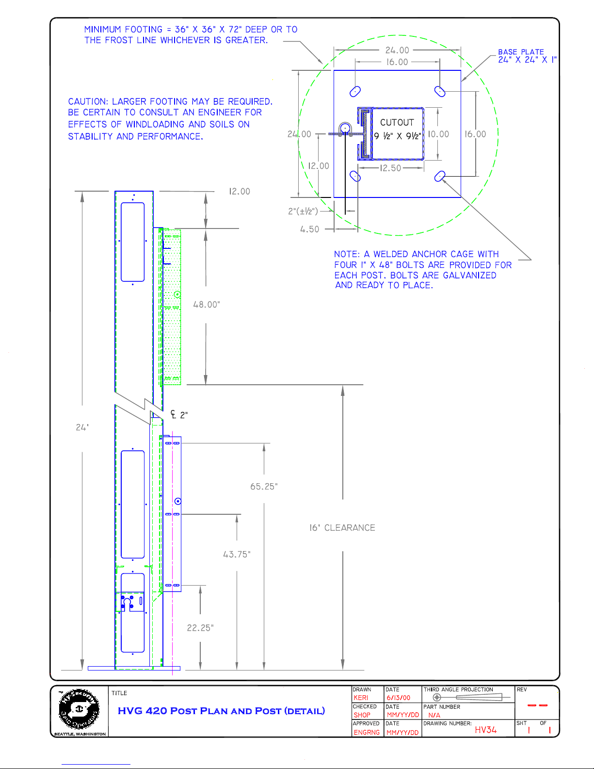
1. The concrete footings for the vertical lift posts must be very substantial. An engineer should be retained to
specify the appropriate footing considering the soil conditions, size of the gate and wind load.
2. The anchor bolts are supplied by Hy-Security as a pre-welded cage and must be installed before the post footings
are poured. Contact Hy-Security if the anchor bolt cages are required in advanced of the posts.
3. Place a nut and flat washer onto each of the threaded anchor bolts protruding from the post foundation. Screw
the nuts down until only two or three threads are showing under the nut. Lay the washer on top of each nut. Verify
that you have enough threads left to project through the base plate and allow for another washer and nut on top.
4. Mount the HVG posts onto the foundation. The two HVG posts must be square with each other across the
opening. The removable access panels are designed to face the protected side of the opening. The HVG post with
the rotary limit switch should be on the same side of the roadway as the controller panel.
5. Place a second washer and nut onto each threaded anchor bolt to lock the posts in place. Before final tightening,
it is critical to verify that the posts are square with each other and that are perfectly level and plumb. Use a plumb
bob or a six foot minimum level to assure the posts are plumb. Use the locking nuts to achieve "plumb" in both
directions and twist the posts (notice the curved slots in the base plate) to achieve "square" with the other post.
6. Mount the controller box on the wall or fence line near the HVG post. The controller panel should be within
50 feet of the post that contains the rotary limit switch.
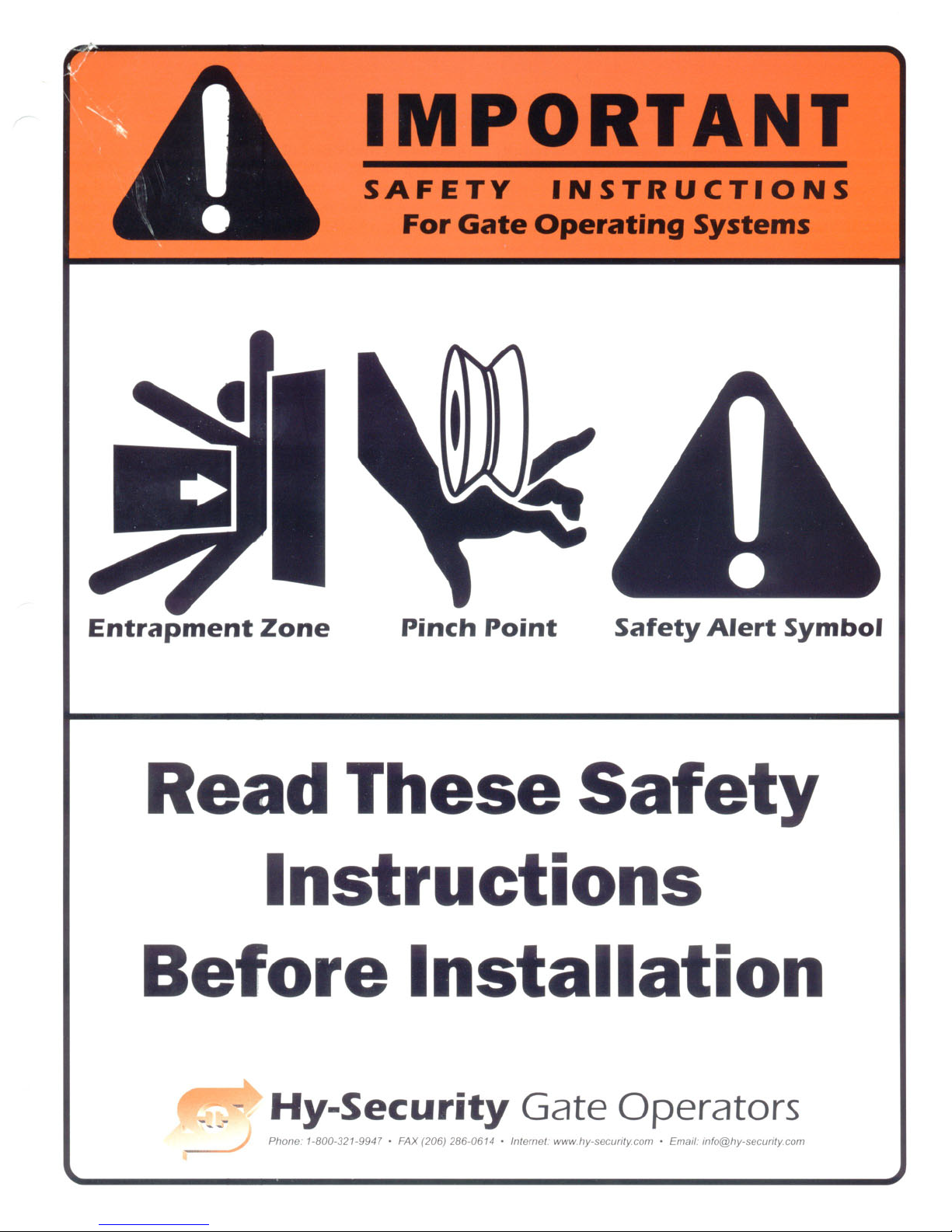
7. Entrapment Protection - Minimum Safeguards:
A. Since automatic gates are not intended for pedestrian use, always install a separate pedestrian walkway
and access gate. Install signs which direct persons to use the pedestrian gate, and to not enter through
the vehicle gate.
B. Be certain that the gate has been constructed such that the opportunity for persons to reach through any
opening have been minimized.
C. Be certain that all access controls are located at least a six foot distance from the gate, to reduce the
possibility of any attempt to reach through in order to operate the gate.
D. Be certain to mount at least two of the enclosed 8 1/2 x 11 warning placards on each side of the gate
to warn users of the hazards of a power operated gate.
E. Button Station Operation: Be certain to mount a warning placard near each button station that warns
that the area must be clear before operating the gate. If there are no entrapment protection sensors to
guard the closing operation of the gate, the push button station must be wired for constant hold
operation only. This is achieved by cutting jumper wires in the control circuit, see drawing E63VT2.
F. Automatic Operation: Entrapment protection sensors must be installed to guard the closing of the
gate. Install photo electric eyes, or attatch edge sensor to create a reversing function. All sensors
guarding the closing direction connect to terminals #1 and #6 in the control box.
Caution: Vehicle detectors are not entrapment protection sensors.
8. Connect appropriate power wiring. Be certain to oversize supply conductors to allow for voltage drop,
especially for single phase machines. Follow the wire schedules (drawing #E16a, b). Route conduit to the control
box. Wirenut the supply power wires to the loose wires at the back of the on/off switch. Be certain to connect a
ground wire.
Page 1 of 2 01/4/01 HV20a
Page 10
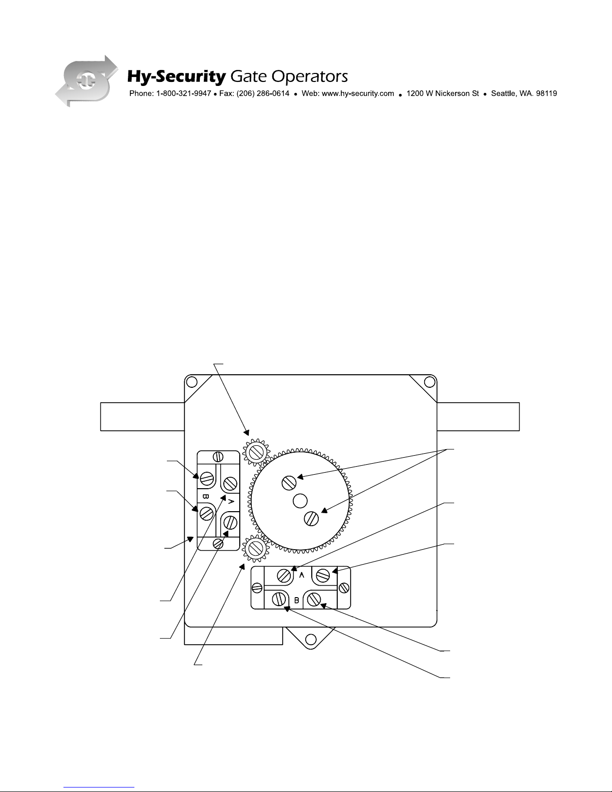
HVG LIMIT SWITCH, SETTING / WIRING INSTRUCTIONS
1. For all HVG operators, eight conductors are required from the limit switch to the control panel.
2. The limit switch is pre-set at the factory, to limit full travel in both directions. Fine tuning may be required in
the field, to suit conditions.
3. To adjust the limits:
a. Loosen the cam clamp screws.
b. Depress the pinion gear, near the switch, engaging the gear teeth.
c. Rotate the cam to trip the limit switch, several inches before full gate travel, to allow the gate to
decelerate.
d. Tighten clamp screws.
e. Repeat steps "a" and "d", for each limit switch.
Pinion for Open Switch
12
Open Limit Switch
8
1A
Cam Clamp Screws
6
3
6
20
Pinion for Close Switch
X1
8/2/00 HV21
Page 11

9. Connect wires between the rotary limit switch and the controller box according to drawing HV21. Connect the
hydraulic hoses to the appropriate sockets. See drawing HV22 and pay close attention to the color coding on the
hoses. The colors should match after hook-up. Run the operator to verify correct functioning. If the hydraulic hoses
were inadvertently reversed, the gate will move in the opposite direction than commanded. If the limit switches
were connected backwards, the operator would not stop when the gate reached its full travel. Never reverse wiring
to the push button station. Replace the plug in the hydraulic reservoir fill hole with the vent cap provided.
10. Remove the plastic shipping plug on the pump manifold near the motor and replace it with the vent cap
supplied.
11. Run the operator to verify correct functioning. It is normal for the bogies to operate slightly out of
synchronization.
12. If the motor runs but nothing moves, close the by-pass valve located near the electric motor or reverse any two
poles of a three phase motor.
13. Temporarily place the gate panel into the opening on the outside side of the property. Before mounting, verify
that the width of the gate does not exceed the dimension between the angle bogie guides. If the gate panel is too
wide it will interfere with the smooth operation of the gate operator and may actually cause damage to the top
covers of the HVG posts.
14. Remove the cap screw on the release sprocket located on the hydraulic motor in the bottom of each post. The
lifting bogies are now free for adjustment so that they may be centered on the gate panel's vertical edge. Mount
the gate panel to the bogies while being certain that no tension is applied that may cause a binding action during
travel. Replace the cap screws in the sprockets. Be sure that they penetrate through the hole in the sprocket and
that the heads are fully seated.
15. Install the 1/8 balancing cables using the supplied cable. Slip the ends with the loops into the upper eye bolts.
Run cables under the white sheaves on the lifting bogies, across the face of the gate panel, over the opposite sheaves
and to the bottom eye bolts. Use the cable clamps that are supplied to hold the cable in minimum tension. The cables
should not hang loose, but the compression spring at the upper eye bolt should not be collapsed. Cut off excess
cable.
16. The vertical lift must be fully counterweighted. The counter weight for each post should be equal to one half
of the total weight of the gate panel. Remove the middle access cover located three feet above the ground. Operate
the gate until fully open.*(see note at end of section) Stop the gate and shut power off. Load the counter weights
into the weight cage which should now be visible through the access cutout. Sheared steel plate 1/2" or 3/4" thick
and 7" square (10 square for HVG 460), makes an easy to handle counterweight material. It is easy to find and
makes fine tuning a snap. NOTE:(one 7" x 7" x 3/4" plate weighs about 10 pounds and one 10 x 10 x 3/4 plate
weighs 20 pounds.)
17. Operate the system a few times to verify that everything is working properly. Set the open and close limits as
required. After testing the basic functions, connect any extra external control wiring and re-test for proper
function.
*NOTE:
Since there is no counter balance for the initial operation, it may be necessary to assist the gate in opening. If necessary, use
a fork lift, block and tackle or manpower for this operation. If the hydralulic pump runs and the gate does not move during
this operation, no harm is done. The pump will simply by-pass through the relief valve and send the fluid back to the tank.
18. Be certain to test the function of the entrapment protection sensors before completion.
For assistance, contact your local distributor.
Page 2 of 2 01/4/01 HV20a
Page 12

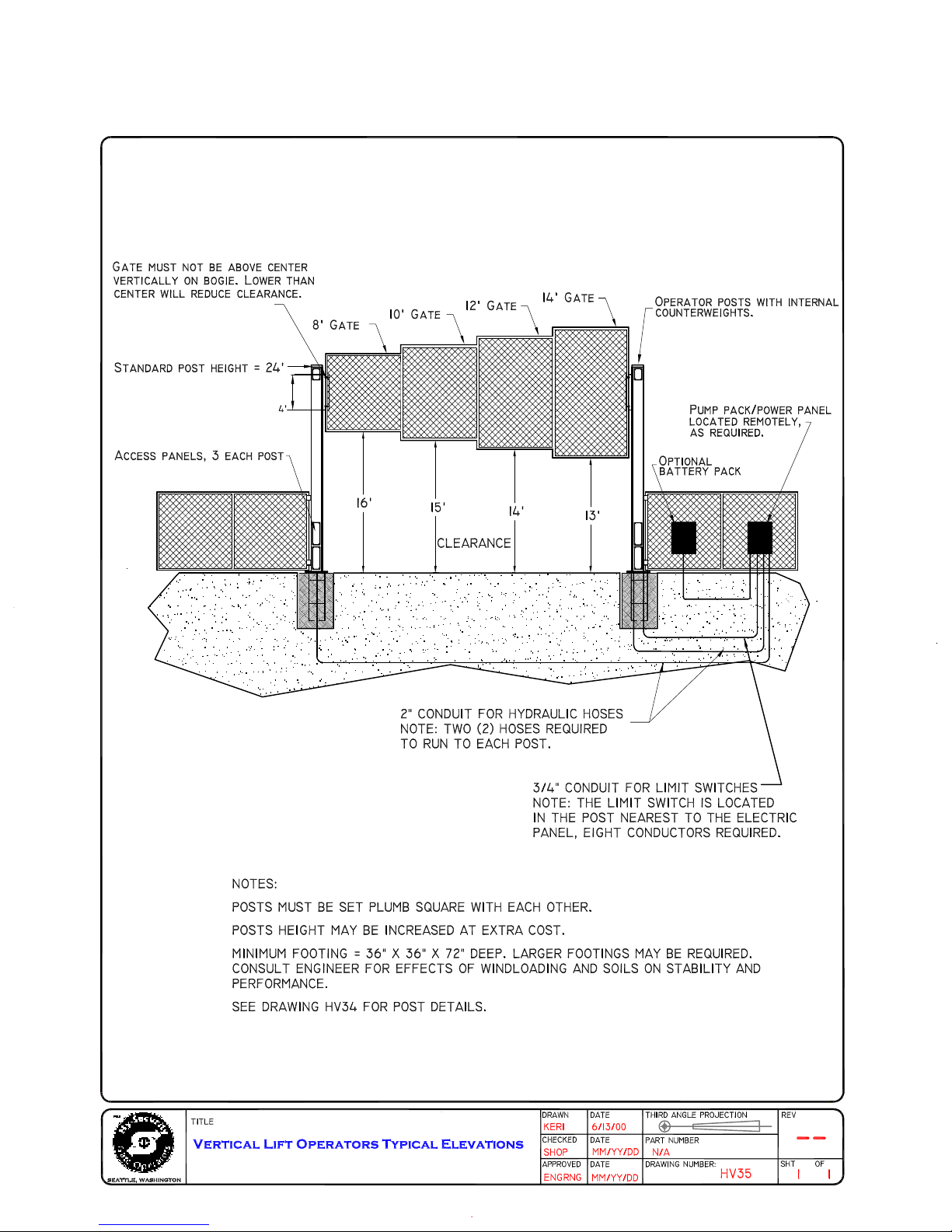
HVG 420 VERTICAL LIFT GATE OPERATOR, SHORT FORM SPECIFICATION:
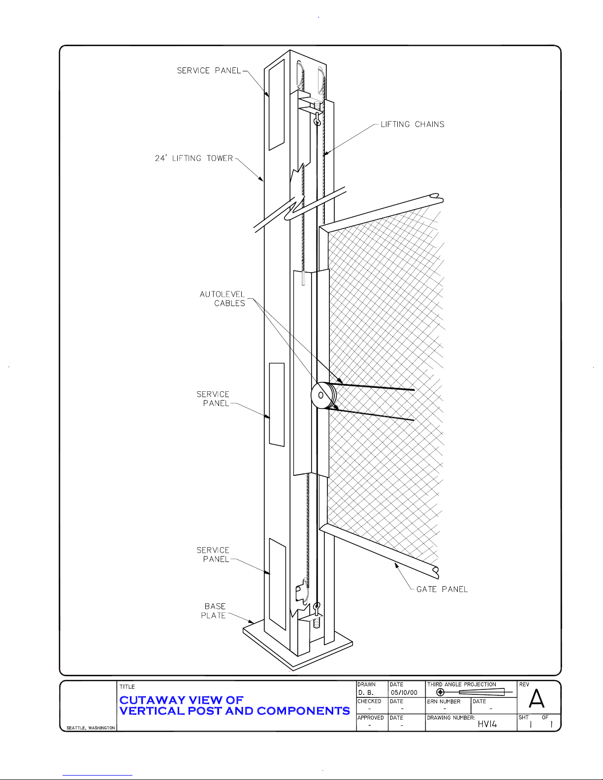
Operator shall consist of two structural, vertical steel towers and all necessary chains, sprockets weight cages
and hydraulic motors to lift a gate vertically to a clear opening height of sixteen feet above grade. The operator
shall also have a separate power package in a housing along with the electrical panel and controls, for remote
location. Steel towers shall be finished at the factory with a zinc coating to provide maximum protection against
corrosion. Lift chains shall be plated to assure corrosion protection. All internal parts shall be prime painted.
"Bogies" shall be provided for lifting the gate panel. A system of balancing cables and fittings shall be provided
to assure that the gate panel will remain level at all times during operation and can not become "keystoned" in
the opening. "Bogies" shall be provided with bearing surfaces to assure that there is no metal-to-metal contact
during operation. Only the finest materials and workmanship shall be used in construction of the gate operator.
Units shall be fully tested prior to leaving the factory. The operator shall be warranted for a period of five years
for defects in manufacturing and for defective parts. Labor to replace defective parts is not covered in the factory
warranty. Hy-Security Gate Operators reserves the right to make engineering changes as they become
available. Model numbers may change to reflect these changes.
Fully formatted specifications and detailed drawings are available upon request.
MANUFACTURED BY:
Hy-Security Gate Operators
1200 W Nickerson St
SEATTLE, WA 98119
(800)321-9947
FAX (206)286-0614
DISTRIBUTED BY:
page 2 of 2 3/2896 HV4 2b
Page 13

Field Hose Measurements for
HVG and HRG Operators
When field measuring for the necessary hose length to order, the following may be helpful:
There is little room in the base of the HRG or the HVG operators and limited room in the
control/power panel, therefore, your field measurements must be very accurate when
calculating the length of the necessary hydraulic hoses. If your dimensions are too little, you
will not reach the connections, if your measurements are too long, you will have trouble
finding space for the excess hose.
Remember that two hoses are needed for each motor or each cylinder. This means that you
need four hoses when you are dealing with a HVG operator and also when you are installing a
HRG 222 (pair) operator.
#5
#4
#3
Be sure to measure accurately the following distances: (the best way is to pull a cord through
the conduit, mark it, and then measure it.)
1. The bottom of the pump/control panel to the bottom of the trench.
2. The total distance across the trench.
3. The distance back up to the bottom of the operator.
4. Add approximately 6" for the hoses to reach up into the operator.
5. Add approximately 24" for the hoses to reach up into the power/control panel.
The part numbers for the hoses are:
1/4" hose for
3/8" hose for HVG: H SFHO 006 4216
HRG: H SFHO 004 SW
3/4" conduit for electrical
only
Roadway
2 ea. hydraulic hoses
in 2" conduit
#2
(if necessary)
For assistance call your distributor .
#2
5/11/00 HV/HR45
#1
Page 14

8/2/00 HV22
Hose Connection Diagram for Vertical Lift Gate Operators
Gold
Red
silver
Splices
Red Gold Red Gold
Road Surface
hydraulic motor
Hydraulic Motor
Clockwise rotation,
closes gate
Counterclockwise rotation
closes gate
Pull longest hoses into bottom of
farthest post, gold and red ends at the
post, gold and silver ends at power/
pump enclosure.
Right hand vertical lift gate shown
From protected side
(Left hand opposite)
Pull short hoses into bottom of
nearest post, gold and red ends at
post, red and silver ends at pump/
power enclosure.
Pump
At posts, mate red to red and gold to gold. At power/pump enclosure, mate gold to gold and red to red on the pump
and splice the two silver ends together with the connector that is supplied.
Page 15

Wire Size SchedulesWire Size Schedules
Wire Size Schedules
Wire Size SchedulesWire Size Schedules
for 1/2-hp through 5-hp motors
Supplying a gate operator with the right electrical service is crucial to the way the performance of
the operator the life of its electrical components. If the wire size used is too small, the voltage loss—
especially during motor starting—will prevent the motor from attaining its rated horsepower. The
percent of horsepower lost is far greater than the percentage of the voltage loss. A voltage loss could
also cause the control components to chatter while the motor is starting, substantially reducing their
life due to the resultant arcing. There is no way to restore the lost performance resulting from
undersized wires, except to replace them; therefore it is much more economical to choose a sufficient
wire size at the initial installation.
The tables on the following page are based on copper wire and allow for a 5% voltage drop. The
ampere values shown are the service factor ampere rating (maximum full load at continuous duty)
of the motor.
Always connect in accordance with the National Electrical Code, article 430, and other local codes
that may apply.
The maximum distance shown is from the gate operator to the power source; assuming that source
power is from a panel box with adequate capacity to support the addition of this motor load. The
values are for one operator, with no other loads applied to the branch circuit. For two operators
applied to one circuit, reduce the maximum allowed distance by half.
Use this chart to determine maximum allowable control wiring distance. If the location required exceeds the distances listed on the
chart at the right, addition of a long
range interface will be neccessary.
Pushbutton Control Wiring
16 ga 125' Maximum
14 ga 200' Maximum
12 ga 300' Maximum
10 ga 500' Maximum
4/14/00 E16a
Page 16

Wire Size for Voltage Drop Over Distance
E16b
Wire Sizes for Power Wiring, Single Phase Distances are shown in the unshaded boxes
Wire Gauge Wire Gauge
Always connect in accordance with the National Electrical Code, article 430, and other local codes that may apply.
Wire sizes for Power Wiring, Three Phase Distances are shown in the unshaded boxes
115 V, SINGLE PHASE 208 V, SINGLE PHASE 230 V, SINGLE PHASE
Amps
10.0 11.06 14.4 27.2 NA NA 5.5 6.1 7.6 14.2 16.2 NA 5.0 5.8 7.2 13.6 14.8 27.0
Horse 1/2hp 3/4hp 1hp 2hp 3hp 5hp 1/2hp 3/4hp 1hp 2hp 3hp 5hp 1/2hp 3/4hp 1hp 2hp 3hp 5hp
Power
12ga
90 75 60 30 290 260 205 110 100 350 300 245 130 120 65
10ga 140 120 100 50 460 415 330 175 155 560 480 385 205 190 105
8ga 220 190 155 80 725 650 525 280 245 880 760 610 325 300 165
6ga 350 300 245 130 1,150 1,040 835 445 390 1,400 1,120 975 515 475 260
4ga 555 480 385 205 1,825 1,645 1,320 710 620 2,220 1,915 1,550 815 750 410
2ga 890 765 620 330 2,920 2,630 2,110 1,130 1,000 3,550 3,060 2,465 1,305 1,200 660
208 V, THREE PHASE 230 V, THREE PHASE 460 V, THREE PHASE
Amps
2.7 3.1 4.2 6.5 6.7 16 2.4 3.0 3.8 6.2 6.4 15.4 1.2 1.5 1.9 3.1 3.2 7.7
Horse 1/2hp 3/4hp 1hp 2hp 3hp 5hp 1/2hp 3/4hp 1hp 2hp 3hp 5hp 1/2hp 3/4hp 1hp 2hp 3hp 5hp
Power
12ga
590 510 375 245 235 100 730 585 460 280 270 115 2,915 2,350 1,850 1,130 1,100 455
10ga
930 810 600 390 375 160 1,160 930 730 450 435 180 4,640 3,710 2,930 1,800 1,740 725
8ga 1,475 1,285 950 615 595 250 1,835 1,470 1,160 710 690 285 7,340 5,870 4,650 2,840 2,750 1,150
6ga 2,350 2,045 1,510 975 945 400 2,925 2,340 1,845 1,130 1,095 455 11,700 9,350 7,400 4,550 4,400 1,800
4ga 3,720 3,240 2,390 1,545 1,500 630 4,625 3,700 2,920 1,790 1,735 720 18,500 14,800 11,700 7,200 7,000 2,900
Page 17

Page 18

Pressure Relief ValvesPressure Relief Valves
Pressure Relief Valves
Pressure Relief ValvesPressure Relief Valves
Adjustment ProceduresAdjustment Procedures
Adjustment Procedures
Adjustment ProceduresAdjustment Procedures
Model Factory Setting
111 Series 750 psi
222 SS, E 1000 psi
222 EX 1300 psi
444 Series 1300 psi
HRG Series 1300 psi
HVG Series 2000 psi
HTG 360 1000 psi
HTG 320-6 1000 psi
HTG 320-3 1000 psi
Side View
The relief valve can be found on the back side (gate side) of the hydraulic power unit. It is the only component located here and has a hex adjusting head and lock nut. To adjust setting, loosen the lock nut screw the
threaded bolt CW for increased pressure, turn CCW to decrease pressure.
HTG 320-2 700 psi
Front View
Pressure relief valves are preset at the factory to utilize maximum available horsepower. The relief valve can
be lowered to smooth starting if necessary. This is most easily done by decreasing the pressure until the gate
operation slows, and then increasing the pressure just enough to provide normal gate speed.
It must be understood that if you reduce the pressure setting, you will lose horsepower to move the gate if
additional resistance (old gate hardware, snow and ice, etc.) is encountered.
Do not attempt to use the relief valve as an entrapment protection device. A photo eye or a gate edge
is the best method to protect pedestrians and reserve power to drive the gate.
5/22/00 G40
Page 19

Page 20

Page 21

Electrical Circuit Options
5/18/00
(111 LS change to 2)
(111 LS change to 8)
Page 22

Long Range Pushbutton ControlLong Range Pushbutton Control
Long Range Pushbutton Control
Long Range Pushbutton ControlLong Range Pushbutton Control
Connection Diagram
Voltage loss over distance is caused as a function of control amperage multiplied by the resistance of
the wiring, and may be expressed: Voltage loss = (wire resistance) X (control amperage). This
limits pushbutton control wiring to the following schedule:
16 ga. wire= up to 125 feet max 12 ga. wire = up to 300 feet max
14 ga. wire = up to 200 feet max10 ga. wire = up to 500 feet max
For applications requiring pushbutton controls from a long distance, or circuits of limited current,
order the factory modification, long range interface. The following schedule indicates the improved
control range using the long range interface:
16 ga. wire = up to 50 miles 20 ga. wire = up to 19 miles
18 ga. wire = up to 30 miles 22 ga. wire = up to 12 miles
FOR BEST PERFORMANCE
USE 20 GAUGE WIRE OR LARGER
Be certain to remove factory-installed jumper (#2 to #4) and also verify that no other external stop
button is connected at #2 and #4.
When the long range interface option is used in conjuction with a pushbutton control, connect to the
operator as shown below:
REMOTE PUSHBUTTON
OPEN
CLOSE
STOP
LONG RANGE
INTERFACE
TERMINAL
STRIP
OPN
CLS
STP
COM
NOTE:
The part number for the long range interface, installed at the factory, A EIIF 001 OCS
The same part designation for the long range interface, in kit form, A EKIF 001 OCS
L T . GREEN
L T . BLUE
ORANGE
YELLOW (COM)
TO TO
C O
O P
N E
T R
R A
O T
L O
S R
BLACK
24V SUPPLY
BLACK
DK GREEN
DK BLUE
WHITE
(COM)
RED
2
10
1
3
2
4
5/10/00 E71
Page 23

Master/Slave Interconnection InstructionsMaster/Slave Interconnection Instructions
Master/Slave Interconnection Instructions
Master/Slave Interconnection InstructionsMaster/Slave Interconnection Instructions
FOR ALL MODELS EXCEPT: HTG 320
Operation of two Hy-Security gate operators as a master/slave pair is simply a matter of correctly
interconnecting the two control circuits. Join the following four wires from the master operator to the slave:
Terminal #1 master to terminal #1 slave,
Terminal #3 master to terminal #3 slave,
Terminal #4 master to terminal #4 slave,
*Terminal #10 master to terminal #10 slave
All stop control inputs must be connected to the master operator only. The slave operator must not have any
connection between terminal #2 and terminal #4, such as a stop button or jumper.
*On DC battery powered operators, interconnect the black wires (-) to the on/off switch instead of the #10
wires. This prevents one operator from powering the other when the disconnect switch is off.
For assistance call your Distributor.
5/15/00 E36
Page 24

Conversion of Primary Operator VoltageConversion of Primary Operator Voltage
Conversion of Primary Operator Voltage
Conversion of Primary Operator VoltageConversion of Primary Operator Voltage
These instructions do not apply to conversions from single phase to three phase
or vice versa. Conversion from one phase to another is not recommended.
Steps required to convert the voltage of an operator within the same phase:
1. The overload must be changed to match the motor current at the new operating voltage.
To do this, remove the overload device from the contactor by loosening the three screws T1, T2 and T3 on the
contactor. Remove all the wires on the overload and replace them exactly the same position on the new
overload. Mount and tighten screws firmly. Be certain the new overload is adjusted to match the motor
nameplate amps that correspond to the new voltage. Note that the existing overload has sufficient range to
accommodate adjustment from 208 volts to 230 volts or vice versa.
2. The primary tap on the control transformer must be changed to the new voltage.
This is accomplished by first reading the label on the top of the control transformer to determine which color
primary lead corresponds to the new voltage to be used. Disconnect the existing primary lead (Caution: Do
not disconnect the primary “Common” lead) and reconnect the primary lead to the same location.
3. The power leads to the motor must be reconnected in the motor junction box to match the new voltage.
You must remove the cover from the junction box on the electric motor. Reconnect the primary leads in the
new configuration shown on the motor nameplate that matches the new voltage. Note this step does not need
to be performed for conversion between 208 volts and 230 volts.
4.The operator must be re-labeled to indicate the new voltage.
Apply new labels to the operator so that the correct primary voltage is indicated.
5. To add a heater you need the following parts: (includes thermostat wire and all mounting hardware):
120 VAC AEKHE 120 250
208-240 VAC AEKHE 240 250
480 VAC (includes relay) AEKHE 480 250
4/13/00 E18
Page 25

Installation Instructions For Gate Reversing Sensing EdgeInstallation Instructions For Gate Reversing Sensing Edge
Installation Instructions For Gate Reversing Sensing Edge
Installation Instructions For Gate Reversing Sensing EdgeInstallation Instructions For Gate Reversing Sensing Edge
1. Securely bolt the edge sensor to the edge of the gate. The edge should line up with the lower corner of the
gate frame.
2. If the reversing edge is to wire directly to the gate operator:
A. Locate a mounting position for a curl cord attatchment, or retracting cord reel holder where there will be
no possibility of the cord rubbing on the moving gate panel.
B. Attatch the cord to the gate in a position that is roughly near the position of the automatic operator,
when the gate is closed.
C. Route the wires to the leading edge of the gate and join to the wires of the reversing edge. Wirenut and
thoroughly tape the connections so that they are not prone to vibrate loose.
D. Join the fixed end of the cord reel or curl cord directly to terminal numbers 1 and 6 inside the control
box of the operator.
3. If the reversing edge is to transmit to the gate operator:
A. Mount the reversing edge transmitter (Multi Elmac Model #3022, or equivalent) onto the gate panel
near the upper corner of the leading edge of the gate.
B. Join the wires of the reversing edge to the two terminals inside of the edge transmitter. Set a unique
code on the “DIP” switches inside the transmitter. Remount the cover of the transmitter and tighten the
screws firmly so that no water will leak inside.
If a receiver for the reversing edge has been prewired inside the operator, proceed directly to step #3D.
C. Mount a commercial style radio receiver* (one with a connector for an external antenna) on the inside
of our operator enclosure. Connect the 24 Volt supply wires to terminal numbers X1 and 10 on the
terminal strip. Connect the radio contact wires to terminal numbers 1 and 6 on the terminal strip.
D. Mount an external antenna onto the top of a fixed post of the fence near the operator. Connect the
antenna into the socket on the radio receiver.
E. Set the “DIP” switches in the receiver to match the same code used in the edge transmitter.
*If there is also to be a radio receiver for a hand held transmitter to operate the gate, be certain to use a two
channel commercial receiver.
4. Test the operation of the reversing edge to be certain that it is functioning. Advise the user of the gate to be
certain to retest this vital function weekly.
4/17/00 E41
Page 26

EMERGENCY OPERATION PROCEDURESEMERGENCY OPERATION PROCEDURES
EMERGENCY OPERATION PROCEDURES
EMERGENCY OPERATION PROCEDURESEMERGENCY OPERATION PROCEDURES
FOR VERTICAL LIFT GATE OPERATORFOR VERTICAL LIFT GATE OPERATOR
FOR VERTICAL LIFT GATE OPERATOR
FOR VERTICAL LIFT GATE OPERATORFOR VERTICAL LIFT GATE OPERATOR
The procedure for manual operation of the vertical
lift gate in case of power failure or a serious
malfunction is as follows:
1. Turn off all electrical power to the controller.
2. Remove the lower access covers on both posts.
3. Remove the Allen head bolt in the three inch
sprocket at the end of the hydraulic motor in each
post. The gate will now operate like an old "sash
weight" type window, with friction as it's only
resistance.
4. Be certain to tie a rope to the bottom of the gate
panel so it can be pulled down again.
5. When the automatic operation is again ready,
reverse the above procedures.
Inspection Panels
6/13/00 HV23
Page 27

MAINTENANCE PROCEDURESMAINTENANCE PROCEDURES
MAINTENANCE PROCEDURES
MAINTENANCE PROCEDURESMAINTENANCE PROCEDURES
HVG VERTICAL LIFT GATE OPERATOR HVG VERTICAL LIFT GATE OPERATOR
HVG VERTICAL LIFT GATE OPERATOR
HVG VERTICAL LIFT GATE OPERATOR HVG VERTICAL LIFT GATE OPERATOR
After proper installation of the vertical lift gate operator, very little maintenance will be required to insure long
and trouble free operation.
MONTHLY:
1. The primary maintenance procedure will be to maintain the drive chain tension. The tension can easily be
checked: Operate the gate to the full open position. Grasp the chain that connects the bottom of the bogie to the
bottom of the weight cage and pull it outward. The chain should always feel somewhat taut, it should never be
loose. This is especially important when the operator is new.
A. To expose the chain tension adjustment area, remove the middle access cover (about three feet above
the ground) and raise the gate to full open.
B. Locate the two threaded rods connected to the top of the weight cage. Loosen the locking nuts on top
of the cage and tighten the nuts on the top inside of the cage. Be sure to tighten the nuts an equal amount
in order to keep the load balanced between the two chains. Tighten the lock nuts.
SEMI-ANNUALLY:
1. Each king post has four bearings with grease fittings. These should be greased semi-annually.
2. Check the balancing cable for correct tension. They should neither sag nor greatly compress the spring at the
top of each post. Also inspect the cables for fraying or snagging, especially where they lay on the sheaves when
the gate is closed.
3. Inspect the cable sheaves to make certain they rotate freely.
4. Check the oil level in the reservoir at the hydraulic pump. It should always be at least 3/4 full. Generally the
oil level should not change. A change would indicate a leaky hose, a serious problem that must be found and
corrected.
5. Apply a light oil to all the chains.
9/2/90 HV25
Page 28

Operator MaintenanceOperator Maintenance
Operator Maintenance
Operator MaintenanceOperator Maintenance
Hydraulic System
Fluid Level: Under normal conditions, hydraulic systems do not consume oil. Before adding any oil, check the
system thoroughly for leaks. Remove the bright metal plug in the tank, fill to plug level, then replace plug. We
recommend our Uniflow hydraulic oil, part number H-004, which is sold in one gallon containers by our distributors. Automatic transmission fluid may be used, although its performance in cold weather will be sluggish unless
the operator is well heated. Do not use brake fluid.
Look for leaks: Occasionally there may be slight seeping at the fittings after some usage. Tightening of the fittings
will usually correct the problem. If the leaking persists, replace "O" rings, fittings or hoses, if required. No further
leaks should occur.
Oil Change: A hydraulic system does not foul its oil, unlike a gas engine, so oil changes do not need to be frequent.
Rather, heat breakdown is the main concern in a hydraulic system. If the unit is subjected to high use, especially in
a warm climate, change the oil more frequently. In general, we recommend draining the reservoir and replacing the
oil at five or ten year intervals.
There are several ways to change the hydraulic oil, depending on the type of operator being serviced. If you
don’t know how to drain the oil, contact your distributor for directions. Refill with new Uniflow hydraulic oil
(available from your distributor). To avoid overfilling, never pour into the port where the black breather cap is
located. Instead, remove only the bright metal plug in the tank. Slowly pour the oil into the tank until the oil is
within one inch of the filler port. Replace the plug and wipe up any spilled oil.
Cold Weather:
1. Check that your reservoir is filled with Uniflow high performance oil.
2. Ice can partly or totally jam gate operation. Check by operating the gate manually.
Electrical Controls
Before servicing, turn off power disconnect switch
No routine maintenance is needed for the electrical system or controls. If the environment is very sandy or dusty, seal
all holes in the electrical enclosure. Blow dust out of the electric panel with compressed air. A qualified electrician may
troubleshoot with the aid of the electrical drawings in Appendix 4.
If it is necessary to call a distributor for assistance, be sure to have your model and serial number ready. Other helpful
information would include the name of the job, approximate date of installation, and the service record of the operator,
especially any work that has been done recently. Be prepared to describe as exactly as you can what the machine is or
is not doing. Describe any unusual sounds or location of oil leaks.
How to Adjust the Pressure Relief Valve: To check your relief valve setting, first disconnect one of the hoses.
Run the operator either open or closed (the gate will not move with the hose disconnected. The relief valve is found
on the rear of the hydraulic power unit. It has a hex adjusting head and lock nut. To adjust, loosen the lock nut and
screw the threaded bolt clockwise for increased pressure, counterclockwise to decrease pressure.
MODEL FACTORY SETTING
111 Series 750 psi
SS, E Models 1000 psi
EX Model 1300 psi
444 Series 1300 psi
Do not attempt to use the relief valve as an entrapment protection device. Photocells or gate edges are the best
methods to protect pedestrians and reserve power to the drive gate.
5/25/00 G39
Page 29

HVG 420 Vertical Lift Gate Operator Parts
2
____ HMOMO 012 WRS Hydraulic Motor W/Quick Disc. Fittings
X
____ HSFHO 004 3/8 Hydraulic Hose, with Fittings
X
____ HSFQD 004 P 1/4 Quick Disconnect (Plug)
X
____ HSFQD 004 S 1/4 Quick Disconnect (Socket)
1
____ HMAMA 222 BVK Manifold, E Type Less Valves
1
____ HVABY 001 CRT Manifold Bypass Valve Cartridge
1
____ HVADI DEL 2P Hydraulic Directional Valve Cartridge (2 Pos)
2
____ HVABK CCG LDN Hydraulic Brake Vlave Cartridge
1
____ HASGA 300 SM Pressure Gauge (3,000 P.S.I)
2
____ MVLSV 001 5.0 5 Plastic Double Cable Sheave
2
____ MTBTC 001 1/8 Cable with End Fittings
8
____ MPTBE 020 UHMW Angle Glide for Bogie
8
____ MPTBE 025 1 Tapped Base Pillow Block Bearing
2
____ MVLSP 420 T-R Top Shaft and Sprocket Assembly (2 Sprockets)
2
____ MVLSP 420 B Bottom Shaft and Sprocket Assembly (3 Sprockets)
1
____ MPTSP 001 3B12 #35-12 Tooth Limit Release Sprocket
1
____ MPTSP 400 R #40-19 Tooth Quick Release Sprocket
140
____ MPTRC 040 #40 Roller Chain, Plated
X
____ MPTRC 035 #35 Roller Chain, Plated (Limit Switch)
X
____ MPTRC 040 CON #40 Master Connecting Link
12
____ MPTRC 040 OFF #40 Offset Connecting Link
2
____ MVLBO 420 Bogie (Gate Mount for HVG 420)
2
____ MVLWC 420 Weight Cage (for HVG 420)
8/2/00 HVG Parts
Page 30

Page 31

LIMITED WARRANTY
(Hydraulically Powered Operators)
Hy-Security Gate Operators warrants all of its manufactured products to the end-user to be
free of defects in material and workmanship. The model 111LS is warranted for a period of
three years from date of shipment. All other hydraulic operators are warranted for a period
of five years from date of shipment.
Drive wheels for slide gate operators are warranted for
a period of two years. Batteries in DC operators and individual replacement parts (that are a
design component of the gate operator) are warranted for one year from the date of
shipment. Even though included as part of a Hy-Security gate operator, accessories carrying
another manufacturers name plate, (unless a design component of the gate operator) shall
carry only the warranty of the specific manufacturer.
Any modification made to factory products will void the warranty unless the modifications
are approved in writing by the factory, in advance of the change. This exclusion does not
apply to normal installation of approved accessories and/or safety devices. This warranty
shall not apply to equipment which has been improperly installed, subjected to negligence,
accident, damage by circumstances beyond Hy-Security Gate Operators' control, or because
of improper operation, maintenance, storage or to other than normal use or service.
Labor to install new parts or remove defective parts, travel time, or standby time is
specifically excluded from this warranty. Freight (surface or air) and all other incidental
costs are NOT covered by this warranty. There are no obligations or liabilities on the part of
Hy-Security Gate Operators for consequential damages arising out of, or in connection with,
the use or performance of this product. Hy-Security Gate Operators assumes no
responsibility for other indirect damages with respect to loss of property, profit or revenue.
This Limited Warranty is valid only in the 50 United States, the District of Columbia and
the Commonwealth of Puerto Rico. Implied warranties, including those of merchantability
and fitness for a particular purpose or application, are limited to one year from date of
shipment.
Defective products that are in warranty should be returned to our factory. At our option, we
may elect to repair or replace, free of charge, any such parts. An invoice will be sent at the
time replacement parts are shipped, and a credit will be issued only after the parts have been
returned undamaged and accepted as defective. No warranty credits will be allowed without
written permission from the factory, and the return of the defective part, together with a
completed Merchandise Return Form (see our Terms of Sale policy for additional details on
the return procedure.) Replacement parts shall carry the remainder of the original limited
warranty or 90 days, whichever is longer.
This Limited Warranty gives you specific rights. You may have others, which vary from
state to state. This Hy-Security Gate Operators’ limited warranty is in lieu of all other
LIMITED WARRANTY
file:///C|/WINNT/PROFILES/btucker/DESKTOP/warranty.htm (1 of 2) [6/21/2001 10:10:39 AM]
Page 32

warranties expressed or implied. This Limited Warranty supersedes all other warranties.
LIMITED WARRANTY
file:///C|/WINNT/PROFILES/btucker/DESKTOP/warranty.htm (2 of 2) [6/21/2001 10:10:39 AM]
 Loading...